p-g-001 technical guide standard pavements …...no warranty or representation (expressed or...
TRANSCRIPT

TECHNICAL GUIDE Standard Pavement Subsurface Drainage Details Issue No: P-G-001 30 June 2014

Technical Guide Standard Pavement Subsurface Drainage Details
Standard Pavement Subsurface Drainage Details Issue No: P-G-001 | 30 June 2014
Page 2 | 48
Printed copies of this document are uncontrolled
About this release
Title: Technical Guide - Standard Pavement Subsurface Drainage Details
Author: James Allen, Pavements Section, Engineering Services Branch
Authorised by: George Vorobieff, Principal Engineer, Pavement and Geotechnical, Engineering Services Branch
Ed/Rev Number
Date Revision description
Ed 1/ Rev 0
June 2014 New Edition
The most recent revision to this Technical Guide P-G-001 (other than minor editorial changes) is indicated by a vertical line in the margin as shown here.

Technical Guide Standard Pavement Subsurface Drainage Details
Standard Pavement Subsurface Drainage Details Issue No: P-G-001 | 30 June 2014
Page 3 | 48
Printed copies of this document are uncontrolled
Foreword and disclaimer
This Guide has been prepared by the Roads and Maritime Services, Engineering Services Branch.
The Guide is intended for use by Pavement practitioners who have satisfactorily completed appropriate training in pavement design.
Persons or organisations external to Roads and Maritime Services considering use of the Guide should obtain independent expert advice applicable to their particular circumstances including advice as to the appropriateness of the Guide for use by them. The Guide has been written for use within the management structure of Roads and Maritime Services and references to responsibility for various actions are expressed in terms of that structure. Persons external to Roads and Maritime Services considering the use of the Guide should consider how those responsibilities would be addressed within their own management structures.
No warranty or representation (expressed or implied) is made by the Roads and Maritime Services, its employees or agents in relation to the accuracy, currency or adequacy of the Guide or that it is fit for purpose. Roads and Maritime Services accepts no responsibility whatsoever arising (whether by statute, in tort, contract or otherwise at law) out of or in connection with the contents or use of the Guide.
The Guide is copyright. Apart from any use as permitted under the Copyright Act 1968, no part may be reproduced by any process without written permission from Roads and Maritime Services.

Technical Guide Standard Pavement Subsurface Drainage Details
Standard Pavement Subsurface Drainage Details Issue No: P-G-001 | 30 June 2014
Page 4 | 48
Printed copies of this document are uncontrolled
Contents
Preface ............................................................................................................................................. 6
1. Introduction ..................................................................................................................... 6
2. Standard subsurface drainage system......................................................................... 7
3. Volume 1 – Design and location.................................................................................... 8
3.1 Introduction to volume 1.................................................................................................... 8
3.2 Locating subsurface drains ............................................................................................... 8
3.3 Design process ................................................................................................................. 9
3.4 Design options for trench drains ..................................................................................... 11
4. Volumes 2 to 5 – Details for specific pavement types .............................................. 12
5. Volume 6 – Model drawings......................................................................................... 12
6. Materials ........................................................................................................................ 12
6.1 Aggregate filter material and no fines concrete (NFC).................................................... 12
6.2 Geotextiles ...................................................................................................................... 13
6.3 Pipes and rigid strips filters ............................................................................................. 13
6.4 Batter outlet headwalls.................................................................................................... 14
6.5 Drainage layers............................................................................................................... 14
7. General conditions ....................................................................................................... 14
7.1 Inlets ............................................................................................................................... 14
7.2 Outlets............................................................................................................................. 14
7.3 Grades ............................................................................................................................ 15
7.4 Trench drain depth.......................................................................................................... 15
7.5 Trench backfill................................................................................................................. 16
7.6 Combining edge and trench drains ................................................................................. 16
7.7 Shallow embankments.................................................................................................... 16
7.8 Drainage layers............................................................................................................... 16
7.9 Integration with other infrastructure ................................................................................ 16 7.9.1 NFC pads and rigid pavements ......................................................................... 17 7.9.2 Clearance to stormwater drainage .................................................................... 17 7.9.3 Clearance to WRSB safety barriers................................................................... 17
7.10 Drainage layers............................................................................................................... 18
8. Non-standard conditions ............................................................................................. 18
8.1 Dispersive or expansive clay subgrades......................................................................... 19
8.2 Acid sulfate soils ............................................................................................................. 19
8.3 Irrigation systems............................................................................................................ 19

Technical Guide Standard Pavement Subsurface Drainage Details
Standard Pavement Subsurface Drainage Details Issue No: P-G-001 | 30 June 2014
Page 5 | 48
Printed copies of this document are uncontrolled
8.4 Overlap in superelevation transitions.............................................................................. 19
8.5 Suitable outlets not available .......................................................................................... 19
8.6 No longitudinal stormwater drainage .............................................................................. 20
8.7 Shoulder widening .......................................................................................................... 20
8.8 Table drain obstructions (piped crossings) ..................................................................... 20
8.9 Upside down pavements................................................................................................. 20
8.10 Stability of undercut batters during construction ............................................................. 20
8.11 Roundabouts................................................................................................................... 21
8.12 Combining subsurface drains with stormwater drainage ................................................ 21
8.13 Bridge approach slabs .................................................................................................... 21
8.14 Open graded asphalt surfacing....................................................................................... 21
8.15 Redundant outlets at critical locations ............................................................................ 21
8.16 Different adjacent pavement structures .......................................................................... 22 8.16.1 Transverse pavement interface drains .............................................................. 22 8.16.2 Longitudinal pavement interface drains............................................................. 22
8.17 Landscaped areas without irrigation ............................................................................... 22
8.18 Sand subgrades.............................................................................................................. 23
8.19 Saline environments ....................................................................................................... 23
9. Construction.................................................................................................................. 23
10. Plan presentation.......................................................................................................... 25
10.1 Horizontal alignment of subsurface drains...................................................................... 25
10.2 Edge details for each pavement type.............................................................................. 25
10.3 Pavement interface drains details................................................................................... 25
10.4 Drainage layer details ..................................................................................................... 25
10.5 Specific details at outlets ................................................................................................ 25
10.6 Other miscellaneous details............................................................................................ 25
10.7 Schedule of subsurface drainage details ........................................................................ 26
11. References..................................................................................................................... 26
12. Glossary......................................................................................................................... 27
13. Abbreviations ................................................................................................................ 27
Appendix A .................................................................................................................................... 29
Appendix B .................................................................................................................................... 33

Technical Guide Standard Pavement Subsurface Drainage Details
Standard Pavement Subsurface Drainage Details Issue No: P-G-001 | 30 June 2014
Page 6 | 48
Printed copies of this document are uncontrolled
Standard Pavement Subsurface Drainage Details
Preface
This edition of the Technical Guide applies to Edition 3 Revision 2 of the Standard Pavement Subsurface Drainage Details (Roads and Maritime, 2012a), hereafter referred to as the ‘Standard Drawings’.
The intent of this document is to provide guidance regarding the basis and use of the Standard Drawings.
1. Introduction
Subsurface drainage systems are installed in roads to either remove water from the subgrade and pavement materials or to intercept water before it reaches the pavement and/or formation structure.
Subsurface drainage design is an integral part of the pavement design process. Any pavement design is to include due consideration of the pavement subsurface drainage requirements.
Design reference documents applicable to the design, construction and maintenance of subsurface drains include Austroads Guide to Pavement Technology Part 10: Subsurface Drainage (Austroads, 2009) and Austroads Guide to Road Design Part 5A: Drainage – Road Surface, Networks, Basins and Subsurface (Austroads, 2013b). The Standard Drawings are based on these design reference documents and standard Roads and Maritime practice.
The Standard Drawings are provided to assist designers develop effective and compliant subsurface drainage design for Roads and Maritime. They provide guidance on locating and detailing subsurface drainage as part of the pavement and geometric design of roads.
There are six volumes in the Standard Drawings:
Volume 1 – Design and location providing guidance and requirements for the need, location and general detailing of subsurface drainage within the road cross section. It includes:
— Instructions for using the standard drawings
— Options for the design of trench drains
— Typical cross sections encountered and the required location of associated subsurface drainage.
Volume 2 – Granular pavement with bituminous surfacing details providing detailed edge designs for subsurface drainage located within and along roads comprising a granular pavement.
Volume 3 – Full depth asphalt pavement details providing detailed edge design for subsurface drainage located within and along roads comprising a full depth asphalt pavement.

Technical Guide Standard Pavement Subsurface Drainage Details
Standard Pavement Subsurface Drainage Details Issue No: P-G-001 | 30 June 2014
Page 7 | 48
Printed copies of this document are uncontrolled
Volume 4 – Asphalt over bound subbase pavement details providing detailed edge designs for subsurface drainage located within and along roads comprising a pavement with thick asphalt base and heavily bound subbase.
Volume 5 – Rigid pavement details providing detailed edge designs for subsurface drainage located within and along roads comprising a rigid pavement.
Volume 6 – Supplementary model drawings; providing model drawings for use with Specifications R33 (Roads and Maritime, 2013b) and R37 (Roads and Maritime, 2013d).
The intent of this document is to provide guidance regarding the basis and use of the details and instructions included in the Standard Drawings.
The standard details assembled in the Standard Drawings are appropriate for typical situations encountered for the majority of projects. They are intended to be adopted for all typical designs as a minimum requirement. They also provide designers and contract managers with guidance on acceptable trench widths and drainage filter material grading.
If situations are encountered which are not covered by the Standard Drawings, then alternative methods of pavement subsurface drainage are required to be developed using these details as guides. Guidance on situations requiring alternative details are discussed in Section 8.
Directives in the imperative in the Standard Drawings, including notes to details (eg ‘trench drain details to be designed in accordance with Table 1 Volume 1’) are mandatory.
The pavement engineer designing the subsurface drainage system must:
Liaise with the designers of the stormwater drainage, utilities and road furniture to ensure that subsurface drains are located without interference from other items.
Liaise with the designer of the formation geometry and stormwater drainage to ensure that subsurface drains can both drain to outlets or pits as appropriate and are not adversely affected by flooding.
Ensure that each pavement layer thickness is detailed to permit construction in accordance with specification requirements and that the minimum thickness of no fines concrete drainage layers is provided below gutters.
2. Standard subsurface drainage system
Roads and Maritime standard drawings and specifications define the following components of subsurface drainage systems:
Trench drains, which are installed within and adjacent to pavements. They are used to drain water from within pavements, intercept ground water and lower the water table.
Edge drains, which are installed in rigid pavements to drain water from the interface between the base and subbase.
Pavement interface drains, which drain the interface between pavements with different structures. They may be orientated transversely or longitudinally.
Intra-pavement drains, which drain water from pavements on steep grades and sag curves where water flows are likely to be more parallel than transverse to the road alignment.
Drainage layers, which are permeable structural formation layers designed to remove water from wet subgrade areas, such as caused by springs or ground water seepage.
Outlets, which may be at stormwater pits or headwalls on batters.

Technical Guide Standard Pavement Subsurface Drainage Details
Standard Pavement Subsurface Drainage Details Issue No: P-G-001 | 30 June 2014
Page 8 | 48
Printed copies of this document are uncontrolled
3. Volume 1 – Design and location
3.1 Introduction to volume 1
Volume 1 of the Standard Drawings includes the following types of subsurface drains:
Trench drains
Edge drains
Drainage layers.
Intra-pavement drains and pavement interface drains are to be considered separately.
3.2 Locating subsurface drains
Subsurface drains are usually installed at the following locations:
Along the low side of pavements
Along the high side of pavements in cuts
Along kerbed medians where infiltration from the median is likely, typically on both edges of the median
Along both sides of the pavement and transversely at cut to fill locations
Transversely at low points in sags
Joints between an existing pavement and an adjoining pavement where pavement courses do not match and course thicknesses or relative permeabilities could create a moisture trap, either longitudinally or transversely
At approaches to bridges, including immediately behind the bridge abutment to the full depth of the abutment, in the subgrade at the interface of the road pavement and the approach slab and along the low side of the approach slab
Toes of embankments
High side of slab anchors required for rigid pavements
Along both sides of the pavement where the crossfall is flatter than 1% in a superelevation development, and transversely at superelevation changes, to limit the length of the longest drainage path within the pavement
The high side of a pavement where seepage is evident, or where water may enter from batters, medians, full-width pavement, service trenches or abutting properties
Areas where the groundwater table is high or seepage is expected such as at springs
Along both sides of a depressed median in fills where the median drain invert level is above the underside of the SMZ and longitudinal grade is less than 2%
Along both sides of a median with a permeable surface (eg landscaped or grassed medians), or generally greater than 2 m wide
Along all sides of a median with a fixed watering system
At other locations deemed necessary by the pavement designer or Roads and Maritime

Technical Guide Standard Pavement Subsurface Drainage Details
Standard Pavement Subsurface Drainage Details Issue No: P-G-001 | 30 June 2014
Page 9 | 48
Printed copies of this document are uncontrolled
Volume 1 of the Standard Drawings provides instructions and requirements regarding the positioning of subsurface drains in typical cross section arrangements likely to be encountered. Specific comments supporting the implementation of subsurface drains as shown on the Volume 1 drawings are included in Appendix A.
Details are not provided in Volume 1 for rural roads without longitudinal piped drainage and which generally have pavement layers that daylight. Refer to Section 8 for comments on draining this type of pavement.
3.3 Design process
The process to be adopted in subsurface drainage design is shown in the flow chart ‘How to use these drawings’ on Sheet 4, Volume 1 of the standard drawings, and reproduced in Figure 1.
Step 1 - match the project cross section being designed with the typical cross sections presented in Volume 1. Cross sections XSP1 to XSP14 included in Volume 1 represent typical four lane divided carriageway freeway cross sections and XSP15 to XSP16 represent typical urban cross sections.
Step 2 - identify the edge detail reference (A01, A02 etc) from the standard cross section that corresponds with the edge of pavement being designed.
Step 3 - identify the pavement type to be constructed at this location (granular, full depth asphalt, asphalt over bound base, rigid).
Step 4 - obtain the Standard Drawing Volume (2 – 5) that corresponds with the pavement type identified in step 3.
Step 5 - select the appropriate standard detail from the volume identified in Step 4 that corresponds with the edge detail identified in step 2 (eg A01-R).
Step 6 - assess the standard detail and consider any specific changes that may be required. Note (g) in the Standard Drawings provides example conditions requiring modification to the standard details. Section 8 of this Technical Guide provides guidance on designing subsurface drainage in some of these conditions.
Step 7 - detail appropriate combinations of trench drain options (trench width versus filter material size) in accordance with Table 1 of Volume 1. With the exception of specific situations identified in step 6 that require a project specific design, the default trench drain should be specified on construction plans as 300 mm wide with F20 aggregate filter material and a pipe. This combination is suitable for any longitudinal grade > 0.5% and provides for each component to be tendered on.
Step 8 - identify relevant model drawings for inclusion in the construction drawings.
Step 9 - produce the construction drawings.
It is accepted that there will be a limited number of Roads and Maritime projects where constraints identified in step 6 make the use of standard details impractical or unfeasible. Some examples of these situations/constraints are discussed in Section 8, together with the guiding principles for the development of alternative subsurface drainage details.

Technical Guide Standard Pavement Subsurface Drainage Details
Figure 1: Flowchart showing the design steps
Standard Pavement Subsurface Drainage Details Issue No: P-G-001 | 30 June 2014
Page 10 | 48
Printed copies of this document are uncontrolled

Technical Guide Standard Pavement Subsurface Drainage Details
3.4 Design options for trench drains
Table 1 of Volume 1 of the standard drawings provides acceptable trench drain configurations and outlet spacing for various combinations of grade, trench width, aggregate filter material and whether a pipe is included for the drains full length. Table 1 is located in the Standard Drawings Volume 1, sheet 4 and Volume 6 as a model drawing and is also included below with supporting comments.
Table 1: Design options for trench drains
For flatter grades with a reduced hydraulic pressure head a more permeable filter material is specified.
A pipe is not required for the drains full length for combinations nominated as not requiring a pipe. However a pipe is always required for the final 5 m of any subsurface drain to facilitate drainage of the trench of filter aggregate material. In the standard case where filter aggregate is not daylighted at a batter outlet, 5 m of corrugated perforated pipe is to be provided at the low end of the aggregate filter material and connected to the non-perforated pipe that connects to the outlet. A note to this effect must be included in the construction plans where required.
The final 5 m of perforated corrugated pipe is to be shown at the base of the trench to facilitate drainage of moisture at the low end of the trench.
The filter aggregate size nominated in the table is a minimum, any larger size filter aggregate up to F20 or no fines concrete is also considered acceptable for the corresponding configuration.
Standard Pavement Subsurface Drainage Details Issue No: P-G-001 | 30 June 2014
Page 11 | 48
Printed copies of this document are uncontrolled

Technical Guide Standard Pavement Subsurface Drainage Details
Standard Pavement Subsurface Drainage Details Issue No: P-G-001 | 30 June 2014
Page 12 | 48
Printed copies of this document are uncontrolled
4. Volumes 2 to 5 – Details for specific pavement types
Volumes 2–5 of the Standard Drawings include standard edge details for the following pavement types:
Granular pavement with bituminous surfacing
Full depth asphalt
Asphalt over bound or lean mix concrete subbase
Rigid (concrete base and LMC subbase).
Pavement configurations different to these will require a specific edge detail to be developed. Development of alternatives should be undertaken in conjunction with Pavement, Material & Geotechnical Engineering’s Flexible Pavement Unit so alternatives are captured for inclusion in future editions of the Standard Drawings.
Details are numbered to correspond with Volume 1. For example, ‘Detail A01-G’ is in Volume 2 for granular pavements and corresponds with the locations in Volume 1 shown as A01 on various cross sections.
Commentary on the details shown in Volumes 2 to 5 of the Standard Drawings is included in Appendix B.
5. Volume 6 – Model drawings
Roads and Maritime model drawings that correspond with construction specifications relating to subsurface drainage have been compiled in Volume 6.
Commentary on the drawings included in Volume 6 of the Standard Drawings is included in Appendix B.
6. Materials
Materials for subsurface drainage systems must comply with the requirements of the relevant Roads and Maritime specification. Comments on the various materials are detailed in the following sections.
6.1 Aggregate filter material and no fines concrete (NFC)
Aggregate filter material must comply with Specification 3580 (Roads and Maritime, 2011a) in order to provide adequate flow capacity. Aggregate filter material must not be placed below trafficked pavements, no fines concrete complying with Specification 3222 (Roads and Maritime, 2011f) must be used whenever a subsurface drain is under a trafficked area of pavement. Consideration should be given to future lane adjustments when considering the need for no fines concrete.
Volume 1 of the Standard Drawings includes the ‘Detailed Design of Trench Drains’ table which provides a systematic approach for the selection of nominal aggregate size based on the grade of the drain, the width of the trench and the pipe type. This is provided to guide designers in acceptable combinations to be shown on the plans.

Technical Guide Standard Pavement Subsurface Drainage Details
Standard Pavement Subsurface Drainage Details Issue No: P-G-001 | 30 June 2014
Page 13 | 48
Printed copies of this document are uncontrolled
A 300 mm wide trench with F20 aggregate filter material and a 100 mm corrugated perforated pipe is generally nominated as this combination is adequate for all grades greater than 0.5%. This combination also includes all elements and can be shown uniformly throughout the plans which simplifies quantities and ensures there is a tendered unit rate for all items.
This table is also included in Volume 6 and should be included in tender documents to guide construction managers in assessing requests to vary the trench dimensions/materials that are shown on the plans.
Sand is no longer permitted for use as a drainage medium in subsurface drains on Roads and Maritime roads. This is due to its reduced permeability and increased chance of becoming clogged when compared to filter aggregate material.
6.2 Geotextiles
Geotextile materials must comply with Specification R63 (Roads and Maritime, 2013f) and 3553 (Roads and Maritime, 2011b). The geotextile acts as a filter and separation medium and must be strong enough to resist puncturing and tearing during installation and in service. In order to fulfil their separation and filtration function, geotextiles must be lapped at joints by the minimum widths provided in the specification.
The durability of geotextiles may be influenced by factors including their potential physical degradation under the influence of ultraviolet light, creep under stress, and mechanical damage during transport and installation. Consequently, geotextiles must be stored and handled strictly in accordance with the manufacturer’s directions and specification requirements.
6.3 Pipes and rigid strips filters
Subsurface drainage pipes must comply with Specifications 3552 (Roads and Maritime, 2011c), 3555 (Roads and Maritime, 2011d) or 3556 (Roads and Maritime, 2012b). Caps and other fittings must be in accordance with the manufacturer’s recommendations to suit the product supplied.
Pipe end caps must be purpose built as supplied by the manufacturer.
Corrugated perforated plastic drainage pipe surrounded by filter aggregate material smaller than F7 must be enclosed in a seamless filter fabric. When surrounded by larger filter aggregate material sizes the filter sock is not necessary as the larger size drainage mediums contain less fines to wash into the pipe.
The choice of pipe (round or strip filter) is up to the designer unless mandated otherwise in the Standard Drawings or the Specifications. A 150 mm high rigid strip filter can be substituted for a 100 mm round pipe.
Pipes other than those covered by Roads and Maritime specifications may occasionally be required for unusual conditions. These non-standard configurations require specific structural design and acceptance must be sought from Roads and Maritime for their implementation.
Flexible strip filter drains (cuspated style core) are not permitted in pavement subsurface drainage applications.

Technical Guide Standard Pavement Subsurface Drainage Details
Standard Pavement Subsurface Drainage Details Issue No: P-G-001 | 30 June 2014
Page 14 | 48
Printed copies of this document are uncontrolled
6.4 Batter outlet headwalls
Standard details for batter outlet headwalls are shown on the model drawings included in Volume 6. The standard items are substantial in mass to prevent movement. In areas of dense vegetation it may be necessary to specify a broader concrete surround to prevent overgrowth and siltation of the outlet.
The location of batter outlets are to be recorded (GPS coordinates) and held in an asset register. This is to enable their location for maintenance.
6.5 Drainage layers
Roads and Maritime requirements for drainage layer materials and construction are set out in Specification R44 (Roads and Maritime, 2013e). Note that geotextile materials are always used in conjunction with drainage layers as required by Specification R44 and the Standard Drawings.
No fines concrete used as a drainage layer, such as in tunnels, is specified in Specification R81 (Roads and Maritime, 2011e).
7. General conditions
7.1 Inlets
Roads and Maritime does not require surface inlets for subsurface drains, except under specific conditions. These have been omitted from general use to reflect maintenance practice and reduce the risk of blockages when inlet structures are damaged. An example of where a clean out or flushing point is required is when the subsurface drainage system is subject to inundation by flood waters. In flood prone areas, an inlet must be provided where outlets are below the design flood level together with a maintenance plan to flush the system immediately after a flood event has subsided.
Inlets are provided at pits where the inlet structure is not trafficable and not subject to damage and the ingress of surface debris. Subsurface drainage inlets at pits must be set at a level above the hydraulic grade line (HGL) of the stormwater pit. At stormwater pits designed with a HGL above the standard location of a subsurface drainage inlet, the inlet is to be omitted with the upstream end of the pipe capped to prevent ingress of the surrounding filter aggregate material.
Every pipe end surrounded by filter aggregate material or NFC (buried inlet ends) must be fitted with a purpose built manufacture’s cap to prevent backfill material entering the pipe. Tied filter sock or duck taped ends are not an acceptable form of capping.
7.2 Outlets
Outlets must discharge into stormwater pits or at batter outlet structures as detailed in Volume 6.
Subsurface drains usually start and end in drainage pits on roads with longitudinal stormwater systems. Those without longitudinal stormwater systems start and end at each batter outlet.
In long cuttings where it is not feasible to outlet subsurface drainage at the specified spacing a carrier pipe is used to connect to a pit or batter outlet. In this case details of the dual pipe requirements and additional trench width required must be shown on the plans.

Technical Guide Standard Pavement Subsurface Drainage Details
Standard Pavement Subsurface Drainage Details Issue No: P-G-001 | 30 June 2014
Page 15 | 48
Printed copies of this document are uncontrolled
Volume 1 of the Standard Drawings includes the table ‘Options for Design of Trench Drains’ which indicates the maximum outlet spacing for trench drains. Spacing is dependent on the grade of the drain which typically matches the longitudinal grade of the pavement surface.
At every outlet, lower the perforated pipe to the base of the trench for the final 5 meters of permeable backfilled trench prior to the outlet.
Non-perforated pipe is used to connect a trench drain to a batter outlet through an impermeable backfill.
7.3 Grades
To ensure flow within the drain, all subsurface drainage must have a grade in excess of 0.5%. In certain circumstances, such as roads with flat longitudinal grades and sag curves, the SMZ will be graded at less than 0.5%. From a drainage perspective this should be avoided where possible. To achieve a 0.5% minimum grade where the road longitudinal grade is less than 0.5%, trenching equipment capable of varying the trench depth at an even rate during excavation is required. At locations where the longitudinal grade of an edge drain constructed without a trench drain below, is less than 0.5%, the edge drain is to be combined with a trench drain.
7.4 Trench drain depth
Trench drains are nominated in the standard drawing as having a minimum depth of 300 mm. This is qualified in the notes as being the minimum depth when the purpose of the drain is solely to remove moisture from the pavement. Where the trench drain is also required to collect or control ground water then a deeper trench drain is required.
In fills that are sufficiently high to prevent groundwater influencing the pavement, the minimum trench drain depth of 300 mm is generally sufficient.
In cuts and where ground water could influence pavement and SMZ moisture conditions then trench drains deeper than 300 mm are warranted. Typically the depth of trench drains in cuts is specified as the greater of:
a) 500 mm below the design floor level
b) 150 mm below the ripped and loosened material
c) 150 mm below the foundation level.
During design, the extent of unsuitable material likely to be encountered or the depth of the constructed foundation level due to stabilisation of a working platform may not be able to be anticipated. Typically 500 mm below the designed floor level (underside of SMZ) will be the greater of the three cases and this level is shown on construction drawings.
During construction the depth may need to be increased to cater for cases (b) and (c), however suitable outlets with sufficient depth to drain any deeper trench drain must also be provided. This situation must be considered during design.
Trench drains deeper than 500 mm may also be required to intercept ground water and to adjust the water table level. Generally where a trench drain deeper than 800 mm is considered necessary to adjust the water table level then a drainage layer should be considered.

Technical Guide Standard Pavement Subsurface Drainage Details
Standard Pavement Subsurface Drainage Details Issue No: P-G-001 | 30 June 2014
Page 16 | 48
Printed copies of this document are uncontrolled
7.5 Trench backfill
Corrugated perforated plastic pipes are always surrounded with filter aggregate materials or NFC. Filter aggregate material is difficult to compact and prevent future movement, any critical locations such as under trafficable pavements must be backfilled with NFC rather than filter aggregate material.
With the exception of parallel carrier pipes, corrugated non-perforated plastic pipes are to be surrounded by low permeability backfill material. Requirements are specified in Specification R33 (Roads and Maritime, 2013b). Where the backfill material cannot be compacted to the density level of the adjacent layer then a cementitious flowable fill can be used.
7.6 Combining edge and trench drains
Edge and trench drains must be overlapped by at least 200 mm when edge drains discharge into trench drains. The interface between the edge drain and the trench drain should not have a geotextile layer between them.
7.7 Shallow embankments
Trench drains in cuts are to be extended into fills for a distance corresponding with the extent of the shallow embankment as defined in Specification R44 (Roads and Maritime, 2013e).
7.8 Drainage layers
Drainage layers may be specified in wet cuts for drainage and in rock cuts for drainage and/or to provide a working platform.
A drainage layer is typically specified in rock cuts with rock strength; UCS > 2 MPa or 0.6 MPa <UCS< 2 MPa and rock block size > 300 mm.
7.9 Integration with other infrastructure
Roads and roadsides are becoming increasingly complex with the infrastructure likely to be present including:
Safety barriers, either concrete, steel or wire rope
Conduits containing hardware supporting Intelligent Transportation Systems
Posts and footings for fences, signs and guideposts
Utilities, including but not limited to stormwater, telecommunication, gas, electricity and water.
This may constrain the opportunity to locate the subsurface drainage system behind the kerb and maintain effective and safe clearances for both construction and maintenance access. In such instances, where there is risk of damaging the subsurface drainage system, consideration should be given to locating the trench immediately below the kerb and gutter. The kerb and gutter itself is likely to be a source of moisture, from behind, and also from in front (except when cast integrally with a concrete slab). To ensure that any moisture is effectively removed from the vicinity of the kerb and gutter, a no fines concrete platform should be placed beneath the kerb and gutter to ensure a pathway for moisture to travel to the subsurface drain, as shown in the Standard Drawings. For construction expediency, the NFC pad and gutter thickness should be detailed to

Technical Guide Standard Pavement Subsurface Drainage Details
Standard Pavement Subsurface Drainage Details Issue No: P-G-001 | 30 June 2014
Page 17 | 48
Printed copies of this document are uncontrolled
match pavement layer thickness. Note there is a specified minimum thickness of no fines concrete drainage layers below gutters, a minimum kerb thickness to prevent cracking and pavement layer thickness limits for compaction of granular materials. If necessary, the minimum thickness of the gutter may be increased to facilitate construction. Kerbs with gutters thicker than standard are to be detailed in plans as modified kerbs.
Typically, the gutter thickness is matched to the base layer thickness. This requires a check that the base thickness is sufficient to achieve the minimum 150 mm thickness in SO kerbs. The NFC pad below the gutter is matched to the subbase thickness and should be a minimum 100 mm thick.
7.9.1 NFC pads and rigid pavements
NFC pads under kerbs tied to rigid pavements have the potential to restrict movement of the base layer. Where a step is created by finishing the NFC below the level of the base/subbase interface the base layer may be constrained, inducing tensile stress in the base. This is most likely to occur due to:
Shrinkage of integrally cast kerb/base slabs during curing
Gravitational effects on pavements with kerbs on the high side of the slab which is sometimes encountered on superelevated pavements in cuts.
In these cases traditional edge drains are preferred. The cost of maintaining any cracking due to this mechanism of restraint needs to be balanced by any increased formation width required to accommodate edge drains where clearances to safety barriers are to be maintained.
7.9.2 Clearance to stormwater drainage
Stormwater drainage and subsurface drainage systems are expected to operate independently of each other except at pits where the two systems are joined at an outlet or inlet.
Typically, stormwater backfill material is permeable in the bed, haunch, side and overlay zones. To prevent pavement subsurface drainage discharging into the stormwater pipe trench and acting as a defacto pavement subsurface drain, it is necessary to separate the subsurface trench drain from the permeable stormwater backfill material. Typical construction permits this by backfilling the stormwater trench with impermeable backfill material above the top of the stormwater SO backfill material, before constructing the pavement subsurface trench drain in the impermeable backfill material. A minimum 100 mm separation should be provided between the trench drain and the SO material. To achieve this, a minimum depth to the stormwater pipe obvert should be set prior to undertaking the stormwater drainage design. The minimum obvert depth should be set allowing for the pipe thickness, overlay zone thickness (typically 150 mm), the 100 mm clearance, the trench drain depth and the pavement thickness.
This clearance applies to both longitudinal and transverse stormwater drainage. Where transverse stormwater levels cannot accommodate this requirement then longitudinal trench drains at this location should be terminated on the uphill side of the stormwater trench and a new run started on the other side.
7.9.3 Clearance to WRSB safety barriers
A minimum 100 mm lateral clearance should be allowed for between edge drains/trench drains and safety barrier post footings and anchor blocks. Where the wire rope safety barrier (WRSB) system is not nominated, a 450 mm diameter post footing and an 1100 mm wide anchor block should be shown on drawings. This may need to be altered as different products are accepted for use on

Technical Guide Standard Pavement Subsurface Drainage Details
Standard Pavement Subsurface Drainage Details Issue No: P-G-001 | 30 June 2014
Page 18 | 48
Printed copies of this document are uncontrolled
classified roads in NSW and also where WRSB installers with poor quality control need an additional tolerance added to this clearance.
Standard edge details show the typical 50 mm offset between the outside edges of the base and subbase layers of rigid pavements which is indicated in the rigid pavement standard drawings. Consideration must be given to the construction contractors likely field performance as there is a 50 mm tolerance on this offset. Where the subbase is finished 100 mm beyond the base slab, the tolerance allowed to cater for clearance to the WRSB footing is reduced by 50 mm, and the allowance of 100 mm may not be sufficient to prevent interference from augered footing excavations.
A minimum 200 mm vertical clearance should be allowed for between the base of a WRSB footing and upper surface of a drainage layer (geotextile wrapping). The 200 mm allows for the 100 mm helical flight locator on the post auger and a 100 mm clearance to avoid the drainage layer. WRSB installers with poor quality control may need an additional tolerance added to this clearance.
7.10 Drainage layers
No fines concrete used as a drainage layer, such as in tunnels, requires special design considerations to ensure that the water head in the layer never reaches the top of the layer. Materials for no fines concrete in this application should use the draft Specification R81 (Roads and Maritime, 2011e) available on request.
To ensure effective operation of the drainage layer, it is imperative that sufficient outlet capacity is provided for the underside trench drains. Where the standard cross section is not used a hydrogeological assessment of potential inflows must be used to calculate the minimum sizes of drains and this information must be provided to Roads and Maritime for review and approval.
Two drainage pipes are always required in the underside trench drain on the low side of the drainage layer. The second pipe is located above the first to provide a redundant outlet in case the lower pipe or the lower part of the drain becomes blocked with fines or for other causes. Nevertheless, trench sizing must be based on the use of one pipe only. Ideally the low corner of a drainage layer will correspond with a stormwater pit for drainage of the layer, where this is not the case then the low ends of both pipes must connect to a solid carrier drain pipe to the outlet.
Underside trench drains are shown on the standard drawings as nominally rectangular in cross section. This shape may not be practical in rock due to rock defect orientation. An alternate shape is acceptable provided that the minimum cross sectional area is maintained and the minimum depth below the base of the drainage layer is achieved. In soils with potentially unstable batters, the side must either be battered sufficiently flat as to permit safe construction or some other technique acceptable to Roads and Maritime adopted.
8. Non-standard conditions
Due to variations in geotechnical conditions, pavement profiles, flood levels, flood frequency, drainage filter material availability and construction techniques it is not feasible to provide a standard detail for every situation encountered on every Roads and Maritime project.
The standard details assembled in the Standard Drawings are appropriate for typical situations encountered for the majority of projects and are intended to be adopted for all typical designs as a minimum requirement. They also provide the construction contractor with flexibility in the selection of trench widths and drainage filter material grading.

Technical Guide Standard Pavement Subsurface Drainage Details
Standard Pavement Subsurface Drainage Details Issue No: P-G-001 | 30 June 2014
Page 19 | 48
Printed copies of this document are uncontrolled
Roads and Maritime accepts that there will be a limited number of projects where project constraints make the use of standard details impractical or unfeasible. In these cases specific designs need to be developed and adopted to ensure subsurface drainage effectiveness.
Any time that the standard details are not used, the designer should make sure that the alternative system will provide adequate pavement subsurface drainage by ensuring that the alternative system provides:
a) The same drainage paths as in the standard detail
b) No less drainage capacity than the standard detail
c) Consideration for ‘safety in design’ principles
d) A similar or lower maintenance regime for the entire pavement/project life.
Various non-standard conditions that require particular consideration are described in the following sections.
8.1 Dispersive or expansive clay subgrades
Subsurface drains must not be located in contact with these materials. Where subsoil drainage is required to penetrate subgrades consisting of these materials, a barrier of low permeability, non-dispersive and non-expansive soil at least 100 mm thick or an impermeable membrane must be provided between the drain and the subgrade soils.
8.2 Acid sulfate soils
Acid sulfate soils must be protected from subsurface drainage elements in a similar manner to dispersive or expansive clay subgrades, unless the acid sulfate soil is appropriately treated. Additionally, concrete elements of the drainage system such as outlet pits must not be in direct contact with acid sulfate soils.
8.3 Irrigation systems
The actual or potential presence of irrigation systems, whether as part of the roadway landscaping or on properties adjacent to the road, must be considered as a significant source of subsurface moisture, trench drains must be included where the pavement design is not based on saturated conditions. Provide trench drains adjacent to all pavements adjoining a landscaped area where an irrigation system is provided. The trench drain should extend to 300 mm below the SMZ level.
8.4 Overlap in superelevation transitions
Subsurface drainage should be included along both sides of the carriageway where transitions in superelevation occur. Overlap trench drains on both sides of the pavement for a minimum length until a pavement crossfall of 1% is achieved in each direction.
8.5 Suitable outlets not available
Should suitable outlet locations not be available, carrier pipes must be used to transport the collected subsurface water to an available and suitable outlet. Plans are to detail the arrangement showing non-perforated pipes lower than the perforated pipes they are receiving water from, a
Technical Guide Standard Pavement Subsurface Drainage Details
Standard Pavement Subsurface Drainage Details Issue No: P-G-001 | 30 June 2014
Page 20 | 48
Printed copies of this document are uncontrolled
minimum clearance between pipes of 2.5 times the filter aggregate material size and trench width sufficient to provide a minimum clearance between any pipe and trench wall of 2.5 times the filter aggregate material size.
8.6 No longitudinal stormwater drainage
In many rural parts of the NSW with drier climates and conditions, the use of longitudinal piped stormwater drainage systems may not be common. These roads typically provide drainage of the pavement layers by daylighting them to the edge of the formation. For these roads, the invert of the adjacent table drains must be below the base of the pavement layers and SMZ by an amount sufficient to ensure that flow or ponding in the table drain cannot rise to the level of the pavement layers or SMZ in the design storm specified for the project. Where these roads are in superelevation, and depending on the climatic conditions and traffic levels, consideration should be given to sealing the high side verge and pavement layers to beyond the hinge point to prevent infiltration of water.
8.7 Shoulder widening
Subsurface drainage must be constructed where shoulders are widened and the permeability of the added shoulder material is such that water can be trapped at the interface with the existing shoulder and pavement material. Dense graded base (DGB) complying with Edition 6 of Specification 3051 (Roads and Maritime, 2013g) is most likely less permeable than DGB’s supplied under earlier editions of the specification. This is likely to create a permeability reversal at the interface of any shoulder widening on the low side of the pavement and would require a pavement interface drain at the widening interface or alternatively specifying a more permeable DGB material. The filter material used in any trench drains under the pavement is required to be No fines concrete (NFC).
8.8 Table drain obstructions (piped crossings)
Longitudinal pipe culverts at property accesses placed at flat grades typically silt up causing upstream ponding of water in the table drain that can infiltrate the pavement. Pipes and culverts must be designed to permit sufficient flow to prevent silting and maintained to provide long term protection for the pavements.
8.9 Upside down pavements
Upside down pavements occur where the base course is more permeable than the subbase. For example, a granular base course placed on a bound subbase. Moisture penetrating the wearing course will permeate through the base and migrate along the surface of the bound layer towards the low side of the pavement. Trench drains extending up to and adjacent to the permeable base material must be provided to drain the whole pavement profile.
8.10 Stability of undercut batters during construction
In order to minimise the project footprint, cut batters are typically designed at their critical angle for stability and the toe of batter terminated at finished surface level. The construction of pavements and subsurface drainage requires further excavation often requiring a vertical excavation at the toe of a batter which may create a batter slope steeper than its critical angle during construction. This situation requires further geotechnical investigation to assess stability.

Technical Guide Standard Pavement Subsurface Drainage Details
Standard Pavement Subsurface Drainage Details Issue No: P-G-001 | 30 June 2014
Page 21 | 48
Printed copies of this document are uncontrolled
8.11 Roundabouts
Subsurface drainage is required along the outside of roundabout median islands and splitter islands unless the whole of the median is surfaced with an impermeable material, such as concrete.
8.12 Combining subsurface drains with stormwater drainage
In situations where trenching for the pavement subsurface drainage system intersects the stormwater (SO) backfill material, the subsurface drainage water will infiltrate into the stormwater backfill, travel through the stormwater backfill material and drain out the stormwater trench drain at the low end, assuming the 3 m perforated pipe is installed. This is an undesirable system as there is no control over the stormwater trench backfill permeability, fines that can clog the outlet are not prevented from migrating into the backfill and piping can lead to the loss of stormwater pipe backfill support.
Stormwater drainage levels are to be set to prevent this interference from occurring.
Where this conflict may be unavoidable due to project constraints, a combined system is required to be designed. Any combined system is to be wrapped in geotextile and have a stormwater backfill material that provides the required stormwater pipe support and filter medium for subsurface drainage. RTA Quality Alert 8 (RTA, 2011) provides guidance on suitable stormwater backfill materials in wet environments. A backfill material that is equivalent to a filter aggregate material’s permeability and satisfies Quality Alert 8 requirements is to be used.
8.13 Bridge approach slabs
Drainage is required at approaches to bridges, including immediately behind the bridge abutment to the full depth of the abutment, a pavement interface drain in the subgrade at the interface of the road pavement and the approach slab, and an edge and trench drain along the low side of the approach slab where the verge may cause an accumulation of water.
8.14 Open graded asphalt surfacing
Open graded asphalt (OGA) should daylight along the low side longitudinal edge so moisture can drain out of the asphalt. Where it is required to finish OGA flush with the kerb lip, a narrow slot in the kerb can be formed to allow water to flow out of the OGA. As a minimum this should be formed at the low point of sags.
At transverse interfaces with a wearing surface other than OGA on the low side of an OGA wearing surface, the interface should be oriented as close as possible to perpendicular to the surface contours to ensure that water is not trapped at the interface. Extend OGA through sags to prevent this situation.
8.15 Redundant outlets at critical locations
At critical locations such as drainage layers and identified springs consider including an additional redundant outlet in case the primary outlet fails due to blocking. The redundant outlet is to be located above the primary outlet if silting of the trench drain is possible, otherwise locate it at the same level with a horizontal offset.

Technical Guide Standard Pavement Subsurface Drainage Details
Standard Pavement Subsurface Drainage Details Issue No: P-G-001 | 30 June 2014
Page 22 | 48
Printed copies of this document are uncontrolled
8.16 Different adjacent pavement structures
At the interface of different pavements a pavement interface drain is used to drain the joint that forms at this location and any other drainage path in the pavement layers that are obstructed by the adjacent pavement. Pavement interface drains can be transverse or longitudinal. Transverse drains are used at the start and end points of projects and changes in pavement types. Longitudinal or skewed drains are typically used where pavements are widened.
Where the new pavement matches the existing pavement both in material type and course thickness then no obstruction to moisture flow can be assumed and no interface pavement drain is required.
8.16.1 Transverse pavement interface drains
Where the pavement crossfall exceeds the longitudinal grade of the pavement then the primary purpose of the interface drain can be considered to be the collection of surface water entering the joint or crack that typically forms at the interface of the different pavements. In this case the pavement interface drain can be located on either side of the joint and extend from 300 mm below the SMZ level to the underside of the pavement.
Where the pavement longitudinal grade exceeds the crossfall then the pavement interface drain is required to collect both surface water entering the joint and moisture migrating through the high side pavement structure. In this case the pavement interface drain is to be located under the pavement on the low side of the joint and extend from 300 mm below the SMZ level to intersect with pavement layers that require draining. For example, where a rigid pavement is on the high side of a joint then locate the pavement interface drain under the adjacent pavement and extend the drain up to a level where it intersects the base/subbase layer interface.
As pavement interface drains are by nature in trafficable areas the filter material used is always to be NFC.
8.16.2 Longitudinal pavement interface drains
Where two pavements of differing structure are separated by a longitudinal joint then a pavement interface drain is used to collect both surface water entering the joint and moisture migrating from the high side pavement towards the kerb. In this case the pavement interface drain is to be located under the low side pavement and extend from 300 mm below the SMZ layer up to a level that intersects pavement layers in the high side pavement that require drainage. For example where a flexible pavement is placed on the low side of a rigid pavement, locate the pavement interface drain under the flexible pavement and extend the drain up to the interface of the rigid pavement base/subbase layer interface.
As pavement interface drains are by nature in trafficable areas the filter material used is always to be NFC.
8.17 Landscaped areas without irrigation
Subsurface drainage must be installed to intercept subsurface moisture from permeable landscaped areas (eg grassed or planted medians and similar surfaces) adjacent to the pavement.

Technical Guide Standard Pavement Subsurface Drainage Details
Standard Pavement Subsurface Drainage Details Issue No: P-G-001 | 30 June 2014
Page 23 | 48
Printed copies of this document are uncontrolled
Where the landscaped area is on the high side of the pavement there is no moisture to be collected from the pavement layers. Trench drains are to be used around the perimeter of the landscaped area to intercept moisture and prevent it from entering the pavement and subgrade. Trench drains are to be extended to 300 mm below the pavement SMZ layer.
Where the landscaped area is on the low side of the pavement, moisture is also to be collected from the pavement layers. Trench drains are to extend from 300 mm below the pavement SMZ layer up to and adjacent to the pavement layers to be drained.
8.18 Sand subgrades
In ‘clean’ sand without plastic fines, the subgrade will perform as a drainage medium and an unsupported vertical walled trench is difficult to construct. In this case edge drains extending down to the top of the sand are required on the low side of a pavement to provide pavement drainage. Geotechnical assessment is required to confirm that the sand will act as a suitable drainage soak. Some very fine dry sands may not be adequate.
8.19 Saline environments
Subsoil drainage of pavements in saline environments must be designed with care in order to protect the pavement from infiltration of saline waters and so as not to accentuate evaporation of saline water via the drainage system. Methods to reduce the sensitivity of new pavement construction to saline damage include raising the pavement level above the general surface level, stabilising the subgrade to reduce its susceptibility to moisture, subsurface drainage systems (but not below the stabilised layer) and extensive tree planting along the road reserve to maintain a low water table level.
9. Construction
Successful construction of subsurface drainage systems requires effective coordination between earthworks, pavement and trenching activities, as well as sequencing with other activities occurring in the vicinity of the subsurface drains. The pavement designer must liaise with designers of the other project elements and with the construction contractor (when known). An understanding of the likely approach to constructing the subsurface drain is required to minimise the risk of producing an incompatible design or introducing inefficiencies to the construction program and to ensure the design intent is achieved.
Roads and Maritime specifications governing construction of subsurface drainage systems are listed on sheet 3, Volume 1 of the Standard Drawings.
Trench drains are typically constructed following completion of the earthworks, as detailed in Specification R33 (Roads and Maritime, 2013b). Specification R33 also permits staged construction of trench drains in accordance with the details shown in Volume 6 Drawing MD.R33.A07.B.2, so that the trench drain is partly constructed before placing the SMZ and then completed after the SMZ is constructed. This same technique may be applied to the top of the SMZ to prevent damage to the top of the drain when constructing adjacent pavement layers. It is recognised that there are efficiencies to be achieved by trenching only once when constructing trench drains in dry environments and in fills where works are planned and graded to prevent water ponding on the works.

Technical Guide Standard Pavement Subsurface Drainage Details
Standard Pavement Subsurface Drainage Details Issue No: P-G-001 | 30 June 2014
Page 24 | 48
Printed copies of this document are uncontrolled
Local factors such as perched water, groundwater, heaving subgrades or other construction requirements may require the installation of subsurface drains to effectively drain the earthworks to facilitate placement of the upper subgrade or pavement courses.
The Standard Drawings provide minimum widths that any lower layer must project beyond pavement edges in order to ensure satisfactory construction and compaction of the overlying course. These are minimum projections which must be provided unless alternative support (such as structures) or construction techniques to prevent uncompacted edges are provided to Roads and Maritime satisfaction. These projections may be altered where appropriate construction techniques are used to ensure compaction is achieved in the overlying layers. While this is feasible on design and construct contracts where the designers and construction contractor work together, on traditional construction contracts it is typically not possible to anticipate what construction practices each potential construction contractor may use. The risks associated with altering these dimensions should be considered before making any change.
Geotextile installation, where included, typically follows trenching. When installing geotextile, it is important that the integrity of the trench wall is maintained and loose material from trench walls or outside the trench is kept out of the excavation. In rock, when it is difficult to provide ‘smooth’ trench walls for the underside of the trench drain, geotextile wrapping of the drain may not be required at the base of the excavation and an aggregate filter alone may suffice, subject to specific assessment and direction from a geotechnical engineer and acceptance by Roads and Maritime.
Overlapping lengths of geotextile must be installed in accordance with Specification R63. Compaction of the granular filter should ensure that good contact is maintained between the geotextile and the trench.
Where an outlet pipe passes through the geotextile a separate piece of geotextile is to be wrapped around the outlet pipe, flared against the side of the geotextile in the filled drain and secured. Similarly, geotextile should be flared, either inwards or outwards against pits.
Outlet structures are typically precast, and can be grouted into place around the pipe. Wire mesh must be used to prevent animals from entering the pipe, refer to Volume 6 of the Standard drawings for the relevant model drawing. All outlets and any surface inlets must be marked as soon as they are completed to help prevent damage during subsequent construction activities.
Trench floors and pipes must be installed to the design levels within permitted construction tolerances to ensure that excess water is not able to build up within the pipe or trench drain. No fines concrete edge drains must be constructed to at least the dimensions shown on the drawings, and where a drain pipe is included in the no fines concrete it must be located so that it is not damaged during placement and compaction of adjacent verge material.
Compaction of granular filter material is carried out by wetting and the use of vibrating plate or rammer type compactors and trench rollers. Saturation of coarse, highly permeable materials cannot be achieved in practice and best compaction occurs in the wet state by use of high frequency, low amplitude vibrating plates.
In staged trench drain construction, the geotextile over the top of the trench must be protected against damage. If necessary, a plug of select material or other material should be placed over the trench to minimise the risk of contamination or damage by other construction activities, and then completely removed prior to construction of the pavement. Note that the seal constructed on top of the SMZ must not cover the top of the trench drain in order to permit drainage into the top of the drain.

Technical Guide Standard Pavement Subsurface Drainage Details
Standard Pavement Subsurface Drainage Details Issue No: P-G-001 | 30 June 2014
Page 25 | 48
Printed copies of this document are uncontrolled
Longitudinal joints or edges of pavement layers must be arranged so that equipment wheels or tracks do not drive directly on the geotextile at the top of a trench drain. If necessary the geotextile must be temporarily protected during pavement construction, but such protection must be completely removed to permit drainage to occur. Alternatives are to delay the final construction of the trench drain. If it is necessary to offset the trench drain from the edge of the pavement to prevent conflict with a rigid pavement subbase during trenching then the edge drain is to cover the trench drain by at least 200 mm.
10. Plan presentation
Construction plans are to include all details necessary to allow construction of the pavement subsurface drainage system in accordance with the construction specification. As a minimum the following aspects of design are to be presented on the construction drawings.
10.1 Horizontal alignment of subsurface drains
Plan sheets are to indicate the different types of drains (edge, trench, carrier, pavement interface, drainage layers), outlets and any required inlets in plan view.
10.2 Edge details for each pavement type
For each pavement type, include separate details for both the high and low side of the pavement in both cuts and fills and shallow embankments. If shallow embankments are treated as cuts (for the sole purpose of subsurface drainage detailing) then clearly identify this and define the criterion that describes a non-shallow embankment. Do not combine multiple scenarios (ie high and low side situation) on one edge detail.
10.3 Pavement interface drains details
Include transverses and longitudinal pavement interface details that are required for the project.
10.4 Drainage layer details
Include drainage layer details that are required for the project. Outlets discharging into down stream trench drains are to be detailed to show the depth of any down stream (receiving) trench drain is at an appropriate level to ensure full drainage of the drainage layer.
10.5 Specific details at outlets
Any outlets not defined in Model Drawings are to be detailed for construction, including arrangements where non-perforated carrier pipes are used as outlets.
10.6 Other miscellaneous details
Any project specific details not defined elsewhere are to be clearly indicted. For example, any interaction with existing subsurface drainage or ground water control systems such as any connections or separation requirements for local counterfort drains are to be shown.

Technical Guide Standard Pavement Subsurface Drainage Details
Standard Pavement Subsurface Drainage Details Issue No: P-G-001 | 30 June 2014
Page 26 | 48
Printed copies of this document are uncontrolled
10.7 Schedule of subsurface drainage details
Include either:
a) A table of edge details showing the edge detail on either side of the pavement along the carriageway design string line at regular intervals not exceeding 20 m and at points coinciding with a change in edge detail type.
b) A table of pavement subsurface drains indicating the edge detail associated with each drain shown on the plan sheet prepared under section 10.1. The table should include edge detail types and start and end points.
11. References
Austroads (2009) Guide to Pavement Technology Part 10: Subsurface Drainage, AGPT 10/09, Austroads, Sydney, NSW.
Austroads (2013a) Guide to Road Design Part 5: Drainage – General and Hydrology Considerations, AGRD 05/13, Austroads, Sydney, NSW.
Austroads (2013b) Guide to Road Design Part 5A: Drainage – Road Surface, Network, Basins and Subsurface, AGRD 05A/13, Austroads, Sydney, NSW.
Austroads (2013c), Guide to Road Design Part 5B: Drainage – Open Channels, Culverts and Floodways, AGRD 05/13B, Austroads, Sydney, NSW.
Youdale, G and Walter, P (2009) Pavement Drainage Specifications and Drawings, RTA Pavements Conference, Roads and Traffic Authority, Sydney, NSW.
RTA (2011) Quality Alert 8 – Backfill of culverts in wet conditions Construction Quality Technical Direction 2009/008, Roads and Traffic Authority, North Sydney, NSW.
Roads and Maritime (2011a) Aggregate filter material for subsurface drainage Specification 3580, Ed 1 Rev 0 , Roads and Maritime Services, North Sydney, NSW.
Roads and Maritime (2011b) Seamless tubular filter fabric Specification 3553, Ed 3 Rev 0 , Roads and Maritime Services, North Sydney, NSW.
Roads and Maritime (2011c) Subsurface drainage pipe (corrugated perforated and non-perforated plastic) Specification 3552, Ed 3 Rev 0 , Roads and Maritime Services, North Sydney, NSW.
Roads and Maritime (2011d) Subsurface drainage pipe (slotted and unslotted fibre-reinforced concrete) Specification 3555, Ed 4 Rev 0 , Roads and Maritime Services, North Sydney, NSW.
Roads and Maritime (2011e) No fines concrete subbase Specification R81, Ed draft, Roads and Maritime Services, North Sydney, NSW.
Roads and Maritime (2011f) No fines concrete (for subsurface drainage) Specification 3222, Ed 1 Rev 1 , Roads and Maritime Services, North Sydney, NSW.
Roads and Maritime (2012a) Standard Pavement Subsurface Drainage Details, Volumes 1-6, Roads and Maritime Services, North Sydney, NSW.

Technical Guide Standard Pavement Subsurface Drainage Details
Standard Pavement Subsurface Drainage Details Issue No: P-G-001 | 30 June 2014
Page 27 | 48
Printed copies of this document are uncontrolled
Roads and Maritime (2012b) Rigid strip filter drain Specification 3556, Ed 3 Rev 1 , Roads and Maritime Services, North Sydney, NSW.
Roads and Maritime (2013a) RMS Supplement to Austroads Guide to Road Design, RTA/Pub. 11.096, Roads and Maritime Services, North Sydney, NSW.
Roads and Maritime (2013b) Trench drains Specification R33, Ed 4 Rev 2 , Roads and Maritime Services, North Sydney, NSW.
Roads and Maritime (2013c) Edge drains Specification R38, Ed 4 Rev 2 , Roads and Maritime Services, North Sydney, NSW.
Roads and Maritime (2013d) Intra-pavement drains Specification R37, Ed 4 Rev 2 , Roads and Maritime Services, North Sydney, NSW.
Roads and Maritime (2013e) Earthworks Specification R44, Ed 4 Rev 1 , Roads and Maritime Services, North Sydney, NSW.
Roads and Maritime (2013f) Geotextiles (separation and filtration) Specification R63, Ed 4 Rev 0 , Roads and Maritime Services, North Sydney, NSW.
Roads and Maritime (2013g) Granular base and subbase materials for surfaced road pavements Specification 3051, Ed 6 Rev 4 , Roads and Maritime Services, North Sydney, NSW.
12. Glossary
Clean out – term used to describe a subsurface drainage inlet at the surface of the pavement, shoulder or surrounding ground surface.
Flushing point – term used to describe a subsurface drainage inlet at the surface of the pavement, shoulder or surrounding ground surface.
Inspection point – term used to describe a subsurface drainage inlet at the surface of the pavement, shoulder or surrounding ground surface.
Surface inlet – term used to describe a subsurface drainage inlet at the surface of the pavement, shoulder or surrounding ground surface.
13. Abbreviations
AC – Asphalt
DGB – Dense graded base
HGL – hydraulic grade line.
LMC – Lean mix concrete
NFC – No fines concrete
OGA – Open grade asphalt
SMZ – Selected material zone

Technical Guide Standard Pavement Subsurface Drainage Details
Standard Pavement Subsurface Drainage Details Issue No: P-G-001 | 30 June 2014
Page 28 | 48
Printed copies of this document are uncontrolled
WRSB – Wire rope safety barrier
UCS – Unconfined compressive strength
SO – Specific Roads and Maritime gutter shape

Technical Guide Standard Pavement Subsurface Drainage Details
Standard Pavement Subsurface Drainage Details Issue No: P-G-001 | 30 June 2014
Page 29 | 48
Printed copies of this document are uncontrolled
Appendix A
Notes for Volume 1

Technical Guide Standard Pavement Subsurface Drainage Details
Standard Pavement Subsurface Drainage Details Issue No: P-G-001 | 30 June 2014
Page 30 | 48
Printed copies of this document are uncontrolled
Volume 1 – Design and Location
Detail Description Commentary
XSP1 Soil Cutting with SO Gutter and Drainage Layer, Narrow Median and Normal Crossfall
Trench drains are included along the low side of each carriageway in conjunction with the drainage layer. Given the narrow median, which is likely to be sealed, the risk of infiltration from the surface is low. As such, trench drains are not included along the high side when the drainage layer extends for the full width of the median. Catch drains are to be included to minimise runoff reaching the pavement.
XSP2 Soil Cutting with SO Gutter and Drainage Layer, Depressed Median and Normal Crossfall
Trench drains are included along the low side of each carriageway in conjunction with the drainage layer. SO kerb may be included in centre median to support stormwater drainage but does not negate the need for trench drains adjacent to the high side of the pavement which are provided where a drainage layer does not extend for the full width of the median. Catch drains to be included to minimise potential runoff reaching the pavement.
XSP3 Soil Cutting with SO Gutter and Drainage Layer, Depressed Median with Full Superelevation
Trench drains are included along the low side of each carriageway and the high side at the cutting face. SO kerb may be included in centre median to support stormwater drainage but does not negate the need for a trench drain adjacent to the high side of the pavement in the median which is provided where a drainage layer does not extend for the full width of the median. The wide median is a likely infiltration point. Catch drains are included to minimise potential runoff reaching the pavement
XSP4 Soil Cutting with Table Drain and Drainage Layer, Depressed Median with Full Superelevation
Trench drains are included along the low side of each carriageway and on the high side at the face of the cutting in superelevation development lengths if the table drain is not below the SMZ layer and on the high side of the pavement in the median where a drainage layer does not extend for the full width of the median. The wide median is a likely infiltration point. The median flow will increase due to superelevation if SO kerb is not included on the low side of the pavement in the median which may warrant SO kerb to be included in the median invert.
XSP5 Soil Cutting with SO Gutter and No Drainage Layer, Depressed Median with Normal Crossfall
Trench drains included along low and high side of carriageways. Median is a likely infiltration point. SO kerb included along low side of carriageways.

Technical Guide Standard Pavement Subsurface Drainage Details
Standard Pavement Subsurface Drainage Details Issue No: P-G-001 | 30 June 2014
Page 31 | 48
Printed copies of this document are uncontrolled
Detail Description Commentary
XSP6 Soil Cutting with Table Drain and No Drainage Layer, Depressed Median with Normal Crossfall
Trench drains included along low and high side of carriageways. Median is a likely infiltration point.
XSP7 Soil Cutting with Table Drain and No Drainage Layer, Depressed Median with Full Superelevation
Trench drains included along low and high side of carriageways. Median is a likely infiltration point. Table drains included along low side of carriageways.
XSP8 Embankment with SO Gutter and Safety Barrier Narrow, Median and Normal Crossfall
Trench drains are included along the low side of each carriageway. Given the narrow median, which is likely to be impermeable, the risk of infiltration from the surface is low. As such, subsurface drainage is not included along the high side. Ensure safety barrier does not interfere with subsurface drainage.
XSP9 Embankment with SO Gutter and Safety Barrier, Depressed Median and Normal Crossfall
Trench drains are included along the low side of each carriageway and along the high side when the depressed median invert is above the base of the SMZ and the longitudinal grade is less than 2%. Where SO gutter is included in the median the need for trench drains adjacent to the high side of pavement is not negated. Ensure safety barrier does not interfere with subsurface drainage by maintaining minimum clearance between edge of trench and post.
XSP10 Embankment with SO Gutter and Safety Barrier, Depressed Median and Full Superelevation
Trench drains are included along the low side of each carriageway and along the high side of the median pavement when the depressed median invert is above the base of the SMZ and longitudinal grade is less than 2%. Ensure safety barrier does not interfere with subsurface drainage. No subsurface drainage along high side embankment due to crossfall and low risk of infiltration into the embankment provided that the embankment is sufficiently high that lateral infiltration into the pavement structure or SMZ cannot occur.
XSP11 Embankment with No SO Gutter and Safety Barrier, Depressed Median and Normal Crossfall
Trench drains are included along the low side of each carriageway and along the high side when the depressed median invert is above the base of the SMZ and longitudinal grade is less than 2%. Where SO gutter is included in the median the need for trench drains adjacent to the high side of pavement is not negated. Ensure safety barrier does not interfere with subsurface drainage by maintaining minimum clearance between edge of trench and post.

Technical Guide Standard Pavement Subsurface Drainage Details
Standard Pavement Subsurface Drainage Details Issue No: P-G-001 | 30 June 2014
Page 32 | 48
Printed copies of this document are uncontrolled
Detail Description Commentary
XSP12 Embankment with No SO Gutter and Safety Barrier, Depressed Median and Full Superelevation
Trench drains are included along the low side of each carriageway and along the high side of the median when the depressed median invert is above the base of the SMZ and the longitudinal grade is less than 2%. No subsurface drainage along high side embankment due to crossfall and low risk of infiltration into the embankment provided that the embankment is sufficiently high that lateral infiltration into the pavement structure or SMZ cannot occur.
XSP13 Side Cutting and Embankment on Natural Cross Slope, Depressed Median and Normal Crossfall
Trench drains are included along the low side of each carriageway. Drainage layer included on carriageway along cutting if wet. Trench drains included on the high side of carriageway in cut and due to likely infiltration from median on the high side of carriageway in fill where the median drain invert is above the base of the SMZ and longitudinal grade is less than 2%.
XSP14 Hard Rock Cutting with SO Gutter and Drainage Layer, Depressed Median and Normal Crossfall
Trench drains are included along both sides of each carriageway in cut. Drainage layer included on carriageways along cuttings if wet or to provide a working platform in hard rock cuttings.
XSP15 Urban Section : 30m Road Reserve Width, Raised Median and Normal Crossfall
Trench drains are included along both sides of the carriageway due to boxed construction. Given the impermeable median, the risk of infiltration from the surface is low and trench drains aren’t provided adjacent to median.
XSP16 Urban Section : Variable Road Reserve Width, Raised Median and Full Superelevation
Trench drains are included along the low sides of the carriageway and the high side where boxed or in cut. Given the impermeable median, the risk of infiltration from the surface is low. Additional trench drain will be needed should drainage layer be included and only for part width of carriageway.

Technical Guide Standard Pavement Subsurface Drainage Details
Appendix B
Notes for Volumes 2 to 6
Standard Pavement Subsurface Drainage Details Issue No: P-G-001 | 30 June 2014
Page 33 | 48
Printed copies of this document are uncontrolled

Technical Guide Standard Pavement Subsurface Drainage Details
Standard Pavement Subsurface Drainage Details Issue No: P-G-001 | 30 June 2014
Page 34 | 48
Printed copies of this document are uncontrolled
Volume 2 – Granular pavement with bituminous surfacing details
Detail Description Commentary
A01-G Trench Drain and Drainage Layer under Low SO Kerb
NFC pad under SO kerb to be minimum 100 mm thick and match adjacent pavement layer for ease of construction. Trench drain through SMZ is to outlet pavement subsurface drain and intercept transverse moisture from outside pavement edge. Trench drain width and filter material needs to be designed (Table 1 – options for design of trench drains). Note the inclusion of two corrugated perforated plastic drainage pipes in low side drainage layer trench drains to cater for any long term siltation. Guide post or safety barrier footings must not penetrate the drainage layer.
A02-G
Narrow Median between Normal Crossfall Pavements with Drainage Layer
Sealed surface of median area required to prevent infiltration. Safety barrier footings must not penetrate the drainage layer.
A03-G
Drainage Layer under High Pavement Edge (Possible Trench Drain)
Single pipe included in drainage layer trench drains in high side drains. Trench drain required between pavement and drainage layer when the median invert is above the underside of the SMZ layer. Trench drain width and filter material needs to be designed (Table 1 – options for design of trench drains). NFC backfill will be required to achieve adequate compaction in granular base layers placed above. Safety barrier footings must not penetrate the drainage layer.
A04-G Trench Drain and Drainage Layer under Low Pavement Edge
Trench drain is required to collect moisture from pavement layers and provide an outlet to drainage layer. It is curtailed at the top of drainage layer. Trench drain width and filter material needs to be designed (Table 1 – options for design of trench drains). NFC backfill will be required to achieve adequate compaction in granular base layers placed above. Trench drain is located under edge of base layer to prevent interference from guide posts or safety barriers but is not to be located under trafficable pavement areas unless backfilled with NFC. The trench drain can be restricted to below the pavement layers (through SMZ only) when the subbase material is proven to have a permeability at least 10 times greater than that of the base. Note the inclusion of two corrugated perforated plastic drainage pipes in low side drainage layer trench drain to cater for any long term siltation. Safety barrier footings must not penetrate the drainage layer.

Technical Guide Standard Pavement Subsurface Drainage Details
Standard Pavement Subsurface Drainage Details Issue No: P-G-001 | 30 June 2014
Page 35 | 48
Printed copies of this document are uncontrolled
Detail Description Commentary
A05-G Trench Drain and Drainage Layer under High SO Kerb
SO kerb placed on pavement material or SMZ. Trench drain through SMZ is to capture moisture from pavement /kerb joint and intercept transverse moisture from outside pavement edge. The trench drain is located at the face of the kerb but must not extend beyond the kerb if backfilled with aggregate filter material as adequate compaction of granular material above it is not possible. Trench drain width and filter material needs to be designed (Table 1 – options for design of trench drains). Guide post or safety barrier footings must not penetrate the drainage layer.
A06-G Trench Drain under Low SO Kerb, No Drainage Layer
Trench drain width and filter material needs to be designed (Table 1 – options for design of trench drains). NFC pad under SO kerb to be minimum 100 mm thick and match adjacent pavement layer for ease of construction. Trench drain to be oriented under the low side of the NFC pad. Minimum trench drain depth typically extended to 500 mm in cuts.
A07-G
High Pavement Edge, No Drainage Layer (Possible Trench Drain)
Trench drain is required to prevent moisture from wet medians affecting pavement and subgrade layers. Trench drain width and filter material needs to be designed (Table 1 – options for design of trench drains) where drain is required. NFC is required in the portion of trench drain extending into pavement layers so that compaction of granular base material above can be achieved and may be required for full trench drain depth. Trench drain is located under edge of base layer to prevent interference from guide posts or safety barriers but is not to be located under trafficable pavement areas unless backfilled with NFC. The trench drain can be restricted to below the pavement layers when the subbase material is proven to have a permeability at least 10 times greater than that of the base.
A08-G Trench Drain under Low Pavement Edge, No Drainage Layer
Trench drain is required to collect moisture from pavement and subgrade layers. Trench drain width and filter material needs to be designed (Table 1 – options for design of trench drains). NFC is required in the portion of trench drain extending into pavement layers so that compaction of granular base material above can be achieved and may be required for full trench drain depth. Trench drain is located under edge of base layer to prevent interference from guide posts or safety barriers but is not to be located under trafficable pavement areas unless backfilled with NFC for full depth. The trench drain can be restricted to below the pavement layers when the subbase material is proven to have a permeability at least 10 times greater than that of the base.

Technical Guide Standard Pavement Subsurface Drainage Details
Standard Pavement Subsurface Drainage Details Issue No: P-G-001 | 30 June 2014
Page 36 | 48
Printed copies of this document are uncontrolled
Detail Description Commentary
A09-G Trench Drain under Low SO Kerb with Safety Barrier, Layer
Trench drain width and filter material needs to be designed (Table 1 – options for design of trench drains). NFC pad under SO kerb to be minimum 100 mm thick and match adjacent pavement layer for ease of construction. Trench drain to be located under low side of NFC pad.
A10-G
Narrow Median between Normal Crossfall Pavements No Drainage Layer
No subsurface drainage required if median is narrow and has a relatively impermeable surface.
A11-G Trench Drain under Low ’SA’ Kerb, No Drainage Layer
Trench drain width and filter material needs to be designed (Table 1 – options for design of trench drains). NFC pad under kerb to be minimum 100 mm thick and match adjacent pavement layer for ease of construction. Trench drain to be located under low side of NFC pad. Minimum trench drain depth typically extended to 500 mm in cuts.
A12-G
Normal Median between Superelevated Pavements, No Drainage Layer
No subsurface drainage required due to likely narrow and relatively impermeable surface and continuous pavement type extending under median. If pavement types vary on either side of the median then trench drains are required on the low side of the discontinuous pavement.
A13-G Trench Drain under Low SO Kerb, No Drainage Layer
Trench drain width and filter material needs to be designed (Table 1 – options for design of trench drains). NFC pad under SO kerb to be minimum 100 mm thick and match adjacent pavement layer for ease of construction. Trench drain to be located under low side of NFC pad. Minimum trench drain depth typically extended to 500 mm in cuts.
A14-G Trench Drain under High ’SA’ Kerb, No Drainage Layer
Trench drain width and filter material needs to be designed (Table 1 – options for design of trench drains). NFC pad under kerb to be minimum 100 mm thick and match adjacent pavement layer for ease of construction. Trench drain to be located under low side of NFC pad. Minimum trench drain depth typically extended to 500 mm in cuts.

Technical Guide Standard Pavement Subsurface Drainage Details
Standard Pavement Subsurface Drainage Details Issue No: P-G-001 | 30 June 2014
Page 37 | 48
Printed copies of this document are uncontrolled
Volume 3 – Full depth asphalt pavement details
Detail Description Commentary
A01-A Trench Drain and Drainage Layer under Low SO Kerb
NFC pad under SO kerb to be minimum 100 mm thick and match adjacent pavement layer for ease of construction. Trench drain through SMZ is to outlet pavement subsurface drain and intercept transverse moisture from outside pavement edge. Note the inclusion of two corrugated perforated plastic drainage pipes in low side drainage layer trench drains to cater for any long term siltation. Guide post or safety barrier footings must not penetrate the drainage layer.
A02-A Narrow Median between Normal Crossfall Pavements with Drainage Layer
Sealed surface of median area required to prevent infiltration. Safety barrier footings must not penetrate the drainage layer.
A03-A Drainage Layer under High Pavement Edge (Possible Trench Drain)
Single pipe included in drainage layer trench drains in high side drains. Trench drain required between pavement and drainage layer when the median invert is above the underside of the SMZ layer. NFC backfill will be required to achieve adequate compaction in base layers placed above. Safety barrier footings must not penetrate the drainage layer.
A04-A Trench Drain and Drainage Layer under Low Pavement Edge
Trench drain is required to collect moisture from pavement layers and provide an outlet to drainage layer. It is curtailed at the top of drainage layer. Trench drain width and filter material needs to be designed (Table 1 – options for design of trench drains). NFC backfill will be required to achieve adequate compaction in pavement layers placed above. Trench drain is located under edge of base layer to prevent interference from guide posts or safety barriers but is not to be located under trafficable pavement areas unless backfilled with NFC. Note the inclusion of two corrugated perforated plastic drainage pipes in low side drainage layer trench drain to cater for any long term siltation. Safety barrier footings must not penetrate the drainage layer.
A05-A Trench Drain and Drainage Layer under High SO Kerb
SO kerb placed on pavement material or SMZ. Trench drain through SMZ is to capture moisture from pavement /kerb joint and intercept transverse moisture from outside pavement edge. The trench drain is located at the face of the kerb but must not extend beyond the kerb if backfilled with aggregate filter material as adequate compaction of pavement material above it is not possible. Guide post or safety barrier footings must not penetrate the drainage layer.
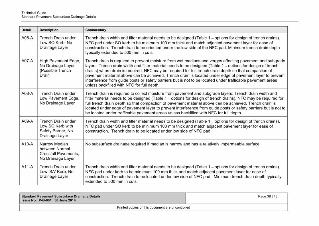
Technical Guide Standard Pavement Subsurface Drainage Details
Standard Pavement Subsurface Drainage Details Issue No: P-G-001 | 30 June 2014
Page 38 | 48
Printed copies of this document are uncontrolled
Detail Description Commentary
A06-A Trench Drain under Low SO Kerb, No Drainage Layer
Trench drain width and filter material needs to be designed (Table 1 – options for design of trench drains). NFC pad under SO kerb to be minimum 100 mm thick and match adjacent pavement layer for ease of construction. Trench drain to be oriented under the low side of the NFC pad. Minimum trench drain depth typically extended to 500 mm in cuts.
A07-A High Pavement Edge, No Drainage Layer (Possible Trench Drain
Trench drain is required to prevent moisture from wet medians and verges affecting pavement and subgrade layers. Trench drain width and filter material needs to be designed (Table 1 – options for design of trench drains) where drain is required. NFC may be required for full trench drain depth so that compaction of pavement material above can be achieved. Trench drain is located under edge of pavement layer to prevent interference from guide posts or safety barriers but is not to be located under trafficable pavement areas unless backfilled with NFC for full depth.
A08-A Trench Drain under Low Pavement Edge, No Drainage Layer
Trench drain is required to collect moisture from pavement and subgrade layers. Trench drain width and filter material needs to be designed (Table 1 – options for design of trench drains). NFC may be required for full trench drain depth so that compaction of pavement material above can be achieved. Trench drain is located under edge of pavement layer to prevent interference from guide posts or safety barriers but is not to be located under trafficable pavement areas unless backfilled with NFC for full depth.
A09-A Trench Drain under Low SO Kerb with Safety Barrier, No Drainage Layer
Trench drain width and filter material needs to be designed (Table 1 – options for design of trench drains). NFC pad under SO kerb to be minimum 100 mm thick and match adjacent pavement layer for ease of construction. Trench drain to be located under low side of NFC pad.
A10-A Narrow Median between Normal Crossfall Pavements, No Drainage Layer
No subsurface drainage required if median is narrow and has a relatively impermeable surface.
A11-A Trench Drain under Low ’SA’ Kerb, No Drainage Layer
Trench drain width and filter material needs to be designed (Table 1 – options for design of trench drains). NFC pad under kerb to be minimum 100 mm thick and match adjacent pavement layer for ease of construction. Trench drain to be located under low side of NFC pad. Minimum trench drain depth typically extended to 500 mm in cuts.

Technical Guide Standard Pavement Subsurface Drainage Details
Standard Pavement Subsurface Drainage Details Issue No: P-G-001 | 30 June 2014
Page 39 | 48
Printed copies of this document are uncontrolled
Detail Description Commentary
A12-A Normal Median between Superelevated Pavements, No Drainage Layer
No subsurface drainage required due to likely narrow and relatively impermeable median surface and continuous pavement type extending under median. If the median extends deeper into the pavement or the pavement types vary on either side of the median then trench drains are required on the low side of the discontinuous pavement.
A13-A Trench Drain under Low SO Kerb, No Drainage Layer
Trench drain width and filter material needs to be designed (Table 1 – options for design of trench drains). NFC pad under SO kerb to be minimum 100 mm thick and match adjacent pavement layer for ease of construction. Trench drain to be located under low side of NFC pad. Minimum trench drain depth typically extended to 500 mm in cuts.
A14-A Trench Drain under High ’SA’ Kerb No Drainage Layer
Trench drain width and filter material needs to be designed (Table 1 – options for design of trench drains). NFC pad under kerb to be minimum 100 mm thick and match adjacent pavement layer for ease of construction. Trench drain to be located under low side of NFC pad. Minimum trench drain depth typically extended to 500 mm in cuts.

Technical Guide Standard Pavement Subsurface Drainage Details
Standard Pavement Subsurface Drainage Details Issue No: P-G-001 | 30 June 2014
Page 40 | 48
Printed copies of this document are uncontrolled
Volume 4 – Asphalt over bound subbase pavement details
Detail Description Commentary
A01-C Trench Drain and Drainage Layer under Low SO Kerb
NFC pad under SO kerb to be minimum 100 mm thick and match adjacent pavement layer for ease of construction. Trench drain through SMZ is to outlet pavement subsurface drain and intercept transverse moisture from outside pavement edge. Note the inclusion of 2 corrugated perforated plastic drainage pipes in low side drainage layer trench drains to cater for any long term siltation. Guide post or safety barrier footings must not penetrate the drainage layer.
A02-C Narrow Median between Normal Crossfall Pavements with Drainage Layer
Sealed surface of median area required to prevent infiltration. Safety barrier footings must not penetrate the drainage layer.
A03-C Drainage Layer under High Pavement Edge (Possible Trench Drain)
Single pipe included in drainage layer trench drains in high side drains. Trench drain required between pavement and drainage layer when the median invert is above the underside of the SMZ layer. NFC backfill will be required to achieve adequate compaction in base layers placed above. Safety barrier footings must not penetrate the drainage layer. Standard profile will generally require cutting the LMC or bound base prior to trenching, where sufficient width of the trench drain is provided and backfilled with NFC to provide sufficient support for compaction of the AC base then the LMC/bound subbase beyond the trench drain may not be required.
A04-C Trench Drain and Drainage Layer under Low Pavement Edge
Trench drain is required to collect moisture from pavement layers and provide an outlet to drainage layer. It is curtailed at the top of drainage layer. Trench drain width and filter material needs to be designed (Table 1 - options for design of trench drains). NFC backfill will be required to achieve adequate compaction in pavement layers placed above. Trench drain is located under edge of base layer to prevent interference from guide posts or safety barriers but is not to be located under trafficable pavement areas unless backfilled with NFC. Note the inclusion of 2 corrugated perforated plastic drainage pipes in low side drainage layer trench drain to cater for any long term siltation. Safety barrier footings must not penetrate the drainage layer. Standard profile will generally require cutting the LMC or bound base prior to trenching, where sufficient width of the trench drain is provided and backfilled with NFC to provide sufficient support for compaction of the AC base then the LMC/bound subbase beyond the trench drain may not be required.

Technical Guide Standard Pavement Subsurface Drainage Details
Standard Pavement Subsurface Drainage Details Issue No: P-G-001 | 30 June 2014
Page 41 | 48
Printed copies of this document are uncontrolled
Detail Description Commentary
A05-C Trench Drain and Drainage Layer under High SO Kerb
SO kerb placed on subbase. Trench drain through SMZ is to capture moisture from pavement /kerb joint and intercept transverse moisture from outside pavement edge. The trench drain is located at the face of the kerb but must not extend beyond the kerb if backfilled with aggregate filter material as adequate compaction of pavement material above it is not possible. Guide post or safety barrier footings must not penetrate the drainage layer. To avoid cutting bound subbase, the subbase material supporting SO kerb may be substituted with other material providing adequate support, eg unbound DGB20.
A06-C Trench Drain under Low SO Kerb, No Drainage Layer
Trench drain width and filter material needs to be designed (Table 1 – options for design of trench drains). NFC pad under SO kerb to be minimum 100 mm thick and match adjacent pavement layer for ease of construction. Trench drain to be oriented under the low side of the NFC pad. Minimum trench drain depth typically extended to 500 mm in cuts. Consideration should be given to layering of pavement layers when determining thickness of support pad to facilitate construction and achieve 150 mm minimum SO thickness to prevent cracking.
A07-C High Pavement Edge, No Drainage Layer (Possible Trench Drain
Trench drain is required to prevent moisture from wet medians and verges affecting pavement and subgrade layers. Trench drain width and filter material needs to be designed (Table 1 – options for design of trench drains) where drain is required. NFC may be required for full trench drain depth so that compaction of pavement material above can be achieved. Trench drain is located under edge of pavement layer to prevent interference from guide posts or safety barriers but is not to be located under trafficable pavement areas unless backfilled with NFC for full depth. Standard profile will generally require cutting the LMC or bound base prior to trenching, where sufficient width of the trench drain is provided and backfilled with NFC to provide sufficient support for compaction of the AC base then the LMC/bound subbase beyond the trench drain may not be required.
A08-C Trench Drain under Low Pavement Edge, No Drainage Layer
Trench drain is required to collect moisture from pavement and subgrade layers. Trench drain width and filter material needs to be designed (Table 1 – options for design of trench drains). NFC may be required for full trench drain depth so that compaction of pavement material above can be achieved. Trench drain is located under edge of pavement layer to prevent interference from guide posts or safety barriers but is not to be located under trafficable pavement areas unless backfilled with NFC for full depth. Standard profile will generally require cutting the LMC or bound base prior to trenching, where sufficient width of the trench drain is provided and backfilled with NFC to provide sufficient support for compaction of the AC base then the LMC/bound subbase beyond the trench drain may not be required.

Technical Guide Standard Pavement Subsurface Drainage Details
Standard Pavement Subsurface Drainage Details Issue No: P-G-001 | 30 June 2014
Page 42 | 48
Printed copies of this document are uncontrolled
Detail Description Commentary
A09-C Trench Drain under Low SO Kerb with Safety Barrier, No Drainage Layer
Trench drain width and filter material needs to be designed (Table 1 – options for design of trench drains). NFC pad under SO kerb to be minimum 100 mm thick and match adjacent pavement layer for ease of construction. . Consideration should be given to layering of pavement layers when determining thickness of support pad to facilitate construction and achieve 150 mm minimum SO thickness to prevent cracking. Trench drain to be located under low side of NFC pad.
A10-C Narrow Median between Normal Crossfall Pavements No Drainage Layer
No subsurface drainage required if median is narrow and has a relatively impermeable surface.
A11-C Trench Drain under Low ’SA’ Kerb, No Drainage Layer
Trench drain width and filter material needs to be designed (Table 1 – options for design of trench drains). NFC pad under kerb to be minimum 100 mm thick and match adjacent pavement layer for ease of construction. Trench drain to be located under low side of NFC pad. Minimum trench drain depth typically extended to 500 mm in cuts.
A12-C Normal Median between Superelevated Pavements, No Drainage Layer
No subsurface drainage required due to likely narrow and relatively impermeable median surface and continuous pavement type extending under median. If the median extends deeper into the pavement or the pavement types vary on either side of the median then trench drains are required on the low side of the discontinuous pavement.
A13-C Trench Drain under Low SO Kerb, No Drainage Layer
Trench drain width and filter material needs to be designed (Table 1 – options for design of trench drains). NFC pad under SO kerb to be minimum 100 mm thick and match adjacent pavement layer for ease of construction. Trench drain to be located under low side of NFC pad. Minimum trench drain depth typically extended to 500 mm in cuts.
A14-C Trench Drain under High ’SA’ Kerb, No Drainage Layer
Trench drain width and filter material needs to be designed (Table 1 – options for design of trench drains). NFC pad under kerb to be minimum 100 mm thick and match adjacent pavement layer for ease of construction. Trench drain to be located under low side of NFC pad. Minimum trench drain depth typically extended to 500 mm in cuts.

Technical Guide Standard Pavement Subsurface Drainage Details
Standard Pavement Subsurface Drainage Details Issue No: P-G-001 | 30 June 2014
Page 43 | 48
Printed copies of this document are uncontrolled
Volume 5 – Rigid pavement details Detail Description Commentary
A01-R Trench Drain and Drainage Layer under Low SO Kerb
NFC pad under SO kerb to be minimum 100 mm thick and match adjacent pavement layer for ease of construction. Trench drain through SMZ is to outlet pavement subsurface drain and intercept transverse moisture from outside pavement edge. Note the inclusion of 2 corrugated perforated plastic drainage pipes in low side drainage layer trench drains to cater for any long term siltation. Guide post or safety barrier footings must not penetrate the drainage layer.
A02-R Narrow Median between Normal Crossfall Pavements with Drainage Layer
Sealed surface of median area required to prevent infiltration. Safety barrier footings must not penetrate the drainage layer.
A03-R Drainage Layer under High Pavement Edge (Possible Trench Drain)
Single pipe included in drainage layer trench drains in high side drains. Trench drain required between pavement and drainage layer when the median invert is above the underside of the SMZ layer. Safety barrier footings must not penetrate the drainage layer or interfere with the trench drain, sufficient clearance to trench drain is to be specified on drawing to prevent any safety barrier footing conflict.
A04-R Trench Drain and Drainage Layer under Low Pavement Edge
Edge drain and associated trench drain is required to collect moisture from pavement and subgrade layers and provide an outlet to drainage layer. It is curtailed at the top of drainage layer. Trench drain width and filter material needs to be designed (Table 1 – options for design of trench drains). Note the inclusion of 2 corrugated perforated plastic drainage pipes in low side drainage layer trench drain to cater for any long term siltation. Safety barrier footings must not penetrate the drainage layer or interfere with the edge drain. Specify an appropriate clearance (min 100 mm) between edge drain and safety barrier footing. Consideration of the constructed offset between base and subbase layer is required as the 50 mm nominal value may not necessarily be achieved in the field.
A05-R Trench Drain and Drainage Layer under High SO Kerb
Single pipe included in drainage layer trench drains in high side drains. SO kerb placed on subbase. Trench drain through SMZ is to intercept transverse moisture from outside pavement edge. The trench drain is located at the face of the LCS. Guide post or safety barrier footings must not penetrate the drainage layer or interfere with the edge drain. Specify an appropriate clearance (min 100 mm) between trench drain and safety barrier footing.
A06-R Trench Drain under Low SO Kerb, No Drainage Layer
Trench drain width and filter material needs to be designed (Table 1 – options for design of trench drains). NFC pad under SO kerb to be minimum 100 mm thick and match adjacent pavement layer for ease of construction. Trench drain to be oriented under the low side of the NFC pad. Minimum trench drain depth typically extended to 500 mm in cuts.

Technical Guide Standard Pavement Subsurface Drainage Details
Standard Pavement Subsurface Drainage Details Issue No: P-G-001 | 30 June 2014
Page 44 | 48
Printed copies of this document are uncontrolled
Detail Description Commentary
A07-R High Pavement Edge, No Drainage Layer (Possible Trench Drain)
Trench drain is required to prevent moisture from wet medians and verges affecting pavement and subgrade layers. Trench drain width and filter material needs to be designed (Table 1 – options for design of trench drains) where drain is required. Safety barrier footings must not penetrate the drainage layer or interfere with the edge drain. Specify an appropriate clearance (min 100 mm) between edge drain and safety barrier footing. Consideration of the constructed offset between base and subbase layer is required as the 50 mm nominal value may not necessarily be achieved in the field.
A07-R High Pavement Edge, No Drainage Layer (No Trench Drain
Where an edge and/or trench drain is not warranted against the rigid pavement (high side application with deep Table drains) place a geotextile layer against the face of the base and subbase layers to prevent the migration of fines between the layers.
A08-R Trench Drain under Low Pavement Edge, No Drainage Layer
Edge and trench drain is required to collect moisture from pavement and subgrade layers. Trench drain width and filter material needs to be designed (Table 1 – options for design of trench drains). Safety barrier footings must not interfere with the edge drain. Specify an appropriate clearance (min 100 mm) between edge drain and safety barrier footing. Consideration of the constructed offset between base and subbase layer is required as the 50 mm nominal value may not necessarily be achieved in the field. In high fills an edge drain only may be used where the trench drain is substituted with a daylighted SMZ layer.
A09-R Trench Drain under Low SO Kerb with Safety Barrier, No Drainage Layer
NFC edge drain is required to collect moisture from base/subbase interface. NFC pad under SO kerb to be minimum 100 mm thick and match adjacent pavement layer for ease of construction. SMZ required to be daylighted where trench drain is not included in association with edge drain in high fills.
A10-R Narrow Median between Normal Crossfall Pavements, No Drainage Layer
No subsurface drainage required if median is narrow and has a relatively impermeable surface.
A11-R Trench Drain under Low ’SA’ Kerb, No Drainage Layer
Trench drain width and filter material needs to be designed (Table 1 – options for design of trench drains). NFC pad under kerb to be minimum 100 mm thick and match adjacent pavement layer for ease of construction. Trench drain to be located under low side of NFC pad. Minimum trench drain depth typically extended to 500 mm in cuts.
A12-R Narrow Median between Superelevated Pavements, No Drainage Layer
No subsurface drainage required due to likely narrow and relatively impermeable median surface and continuous pavement type extending under median. If the pavement types vary on either side of the median then trench drains are required on the low side of the discontinuous pavement.

Technical Guide Standard Pavement Subsurface Drainage Details
Standard Pavement Subsurface Drainage Details Issue No: P-G-001 | 30 June 2014
Page 45 | 48
Printed copies of this document are uncontrolled
Detail Description Commentary
A13-R Trench Drain under Low SO Kerb, No Drainage Layer
Trench drain width and filter material needs to be designed (Table 1 – options for design of trench drains). NFC pad under SO kerb to be minimum 100 mm thick and match adjacent pavement layer for ease of construction. Trench drain to be located under low side of NFC pad. Minimum trench drain depth typically extended to 500 mm in cuts.
A14-R Trench Drain under High ’SA’ Kerb, No Drainage Layer
Trench drain width and filter material needs to be designed (Table 1 – options for design of trench drains). NFC pad under kerb to be minimum 100 mm thick and match adjacent pavement layer for ease of construction. Trench drain to be located under low side of NFC pad. Minimum trench drain depth typically extended to 500 mm in cuts.
A15-R Trench Drain and Drainage Layer under Low Integral SO Kerb
Edge drain to capture moisture from base/subbase interface. Trench drain through SMZ is to outlet pavement subsurface drain and intercept transverse moisture from outside pavement edge. Note the inclusion of 2 corrugated perforated plastic drainage pipes in low side drainage layer trench drains to cater for any long term siltation. Guide post or safety barrier footings must not penetrate the drainage layer or interfere with the edge drain. Specify an appropriate clearance (min 100 mm) between edge drain and any safety barrier footing. Consideration of the constructed offset between base and subbase layer is required as the 50 mm nominal value may not necessarily be achieved in the field.
A16-R Trench Drain and Drainage Layer under High Integral SO Kerb
Single pipe included in drainage layer trench drains in high side drains. SO kerb placed on subbase. Trench drain through SMZ is to intercept transverse moisture from outside pavement edge. The trench drain is located at the face of the LCS. Guide post or safety barrier footings must not penetrate the drainage layer or interfere with the edge drain. Specify an appropriate clearance (min 100 mm) between trench drain and safety barrier footing.
A17-R Trench Drain under Low Integral SO Kerb, No Drainage Layer
Trench drain width and filter material needs to be designed (Table 1 – options for design of trench drains). Minimum trench drain depth typically extended to 500 mm in cuts. The trench drain is located at the face of the LCS. Guide post or safety barrier footings must not penetrate the drainage layer or interfere with the edge drain. Specify an appropriate clearance (min 100 mm) between trench drain and safety barrier footing.
A18-R Trench Drain under Low Integral ’SA’ Kerb, No Drainage Layer
Trench drain width and filter material needs to be designed (Table 1 – options for design of trench drains). Minimum trench drain depth typically extended to 500 mm in cuts. The trench drain is located at the face of the LCS. Guide post or safety barrier footings must not penetrate the drainage layer or interfere with the edge drain. Specify an appropriate clearance (min 100 mm) between trench drain and safety barrier footing.
A19-R Trench Drain under Low Integral SO Kerb, No Drainage Layer
Trench drain width and filter material needs to be designed (Table 1 – options for design of trench drains). Minimum trench drain depth typically extended to 500 mm in cuts. The trench drain is located at the face of the LCS. Guide post or safety barrier footings must not penetrate the drainage layer or interfere with the edge drain. Specify an appropriate clearance (min 100 mm) between trench drain and safety barrier footing.

Technical Guide Standard Pavement Subsurface Drainage Details
Standard Pavement Subsurface Drainage Details Issue No: P-G-001 | 30 June 2014
Page 46 | 48
Printed copies of this document are uncontrolled
Detail Description Commentary
A20-R Trench Drain under Low Integral SO Kerb with Safety Barrier, No Drainage Layer
NFC edge drain is required to collect moisture from base/subbase interface. SMZ required to be daylighted where trench drain is not included in association with edge drain in high fills.

Technical Guide Standard Pavement Subsurface Drainage Details
Standard Pavement Subsurface Drainage Details Issue No: P-G-001 | 30 June 2014
Page 47 | 48
Printed copies of this document are uncontrolled
Volume 6 – Supplementary model drawings
Detail Description Commentary
MD.R33.A04.D.0 (Sheet 1)
Batter Outlet Structures for Subsurface Drains
These are typical structures utilised where subsurface drainage outlets are on batters. A paved area in the vicinity of the structure to minimise the risk of batter erosion may also be required.
MD.R33.A04.D.0 (Sheet 2)
Batter Outlet Structures for Subsurface Drains
This sheet details provide plan and cross section details for batter outlet structures. Perforated pipe is located at the base of the trench drain at the outlet to prevent water ponding in the trench.
MD.R33.A06.B.2 (Sheet 1)
Details for Trench Drains
This sheet includes details for placing geotextiles in trench drains. Note the minimum 500 mm overlap required for placement of geotextile.
MD.R33.A06.B.2 (Sheet 2)
Details for Trench Drains
This sheet provides design guidance for the determination of trench width, selection of Aggregate Filter Material and decision regarding inclusion of pipe based on grade of drain.
MD.R33.A07.B.2 Stage Construction of Trench Drain
This sheet outlines a staged construction methodology for a trench drain, and provides guidance on when commencement of drain construction occurs prior to placement of SMZ.
MD.R33.A08.B.2 Combined Stormwater and Subsurface Drainage Layout
Details indicate the general arrangement where a trench drain is located above a stormwater pipe. The two systems operate independently when constructed in accordance with standard specifications. A minimum 100 mm of impermeable material is required between the base of the trench drain and the top of the stormwater support material to prevent moisture draining into the stormwater backfill material.
The special case where the stormwater backfill material acts as a trench drain requires specific design and detailing which are not covered by the standard arrangement in this drawing.
It is noted that the subsurface drainage at the outlet must be located above the stormwater pipe obvert and pit HGL.

Technical Guide Standard Pavement Subsurface Drainage Details
Standard Pavement Subsurface Drainage Details Issue No: P-G-001 | 30 June 2014
Page 48 | 48
Printed copies of this document are uncontrolled
Detail Description Commentary
MD.R37.A01.B.2 Intra-pavement Drains
Intra-pavement drains drain water from pavements on steep grades and sag curves where water flows are likely to be more parallel than transverse to the road alignment. They are typically located transversely (or occasionally diagonally) across the pavement with an aim to collect subsurface moisture flowing longitudinally through the subbase and/or SMZ. The backfill must comprise NFC and connections to the longitudinal trench or edge drains must be provided to the low side/s of the carriageway in which they are installed.