p. dewdney herzberg institute of astrophysics national research council canada the evla correlator
TRANSCRIPT

N ational R esearch C ounci lC anada
C onsei l national de recherchesC anada
P. Dewdney Herzberg Institute of Astrophysics
National Research Council Canada
The EVLA Correlator

P. Dewdney EVLA Review - May 2006 2N ational R esearch C ounci lC anada
C onsei l national de recherchesC anada
Outline
1. Correlator Performance Goals2. Hardware Progress3. Software Progress4. System Progress5. Prototype Testing6. Installation Estimates7. Funding, Budget & Schedule8. Risk Issues

P. Dewdney EVLA Review - May 2006 3N ational R esearch C ounci lC anada
C onsei l national de recherchesC anada
Key EVLA Processing Capabilities
Deep ImagingPolarization
8 GHz Bandwidth (dual polarization). Full polarization processing. Wide-field imaging.
Narrow spectral linesWideband searches
16,000 channels at max. bandwidth (BW). >106 channels at narrow BWs. Spectral resolution to match any linewidth. Spectral polarization (Zeeman Splitting).
8 tunable 2 GHz wide bands. Each band - 16 tunable sub-bands. Sub-band – independent spectral resolution. Simultaneous line and continuum.
Flexibility Many resources
High time resolution 1000 pulsar “phase bins”. “Single-dish” data output to user
instruments. Very fast time sampling (<20 s).

EVLA Correlator System Diagram

Significant Events Since Dec. 2004
• Correlator Chip CDR – Jan/05• Software Review – Jan/05.• Correlator Preliminary Design Review – July/05.• Software Review – Mar/06.• Prototype Correlator chip wafers fab’d – Feb/06.• Prototype chip delivery – early Jun/06.• PCB fabricator contract signed – Jan/06.• Baseline Board prototype delivery – Jun/06.• Station Board prototype delivery – est. Aug/06.

P. Dewdney EVLA Review - May 2006 6N ational R esearch C ounci lC anada
C onsei l national de recherchesC anada
Hardware Progress• FPGA’s
– All FPGA’s are designed, including the Filter Chip.• Station board
– Layout is close to completion, including Design-for-Manufacture approval.– Presently undergoing signal integrity simulation.– Prototype fabrication order expected in June.
• Baseline Board– Prototype fabrication under way.
• Phasing board– Draft specification (RFS) released.– Deferred in time but not reduced in priority.
• Other boards– Prototypes for all other boards already fabricated.– Fan-out board needs redesign for better signal margins.
• System– Racks designed and prototyped; thermal analysis done.– Power system RFP draft written.– Reliability analysis system in place – first draft of analysis complete.

Station Board Layout
• “Daughter” Board - brown.
• Power Supplies – pink.
• FPGA’s – Green
• Connectors – light brown and white.
• ~5000 parts.
• 140 required for EVLA.
Size: ~510 x ~410 mm
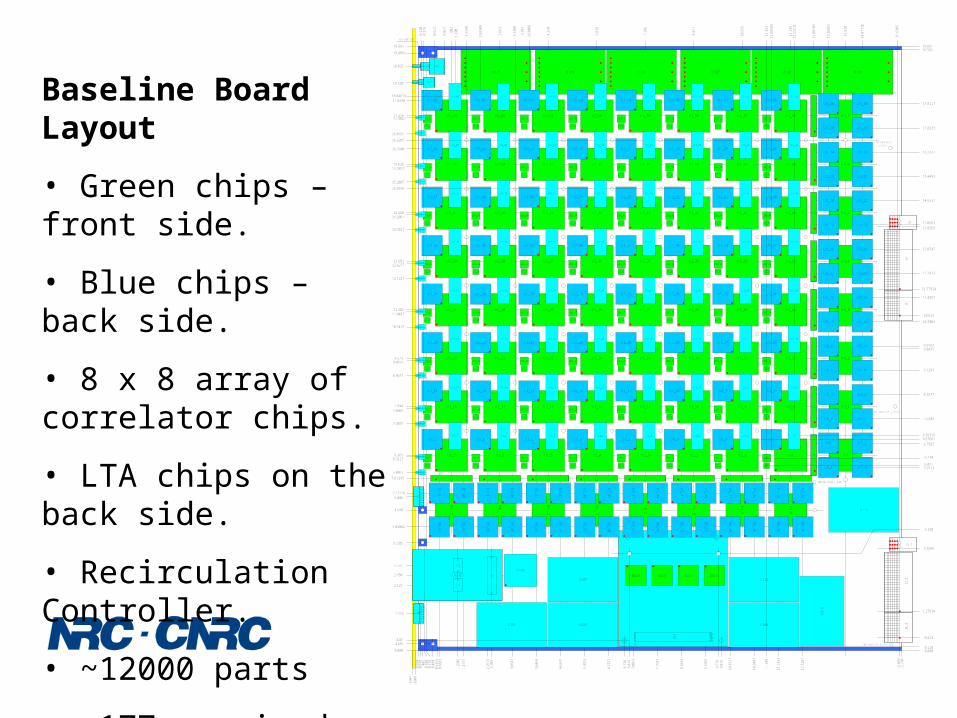
Baseline Board Layout
• Green chips – front side.
• Blue chips – back side.
• 8 x 8 array of correlator chips.
• LTA chips on the back side.
• Recirculation Controller.
• ~12000 parts
• ~177 required for EVLA.
0.0000.118
19.68719.569
9.8435
0.413
0.00
0-.
1000
-.19
84
.140
5
0.000
.2185
19.4685
19.687
0.27
6
3.5205
15.6
8915
.748
1.27914
3.3265
10.913
11.77914
13.8265
15.6
102
6 x .106" DIA
J1_1
J2_1
J3_1
J1J2
J3
14.4
7118
13.9
20
12.8
8705
12.1
35
10.5
56
8.97
7
7.39
8
5.81
9
4.24
0
2.66
1
1.08
2
17.418
15.839
14.260
12.681
11.102
9.523
7.944
6.365
5.61295
4.580
13.3
6882
8.3377
7.5503
5.9713
6.7587
9.1293
9.9167
10.7083
11.4957
12.2873
13.0747
13.8663
14.6537
15.4453
16.2327
17.0243
17.8117
5.13118
4.02882
12.5
287
11.7
413
10.9
497
10.1
623
9.37
07
8.58
33
7.79
17
7.00
43
6.21
27
5.42
53
4.63
37
3.84
63
3.05
47
2.26
73
1.47
57
0.68
83
CAGE1
CAGE22.125
2.775 CAGE3
CAGE4
0.07
8
2.450 CAGE5
0.18
8
SW1123
SW2
3
2
1
123
57
91
113
46
81
0121
4J6
123
57
91
113
46
81
0121
4J7
AB
CD
132
J10
U100
U150 U151 U152 U153
U425 U109 U113 U427 U110 U428
U1_7
U2_7
U7_7
L602_7U1_6
U2_6
U7_6
L602_6U1_5
U2_5
U7_5
L602_5U1_4
U2_4
U7_4
L602_4U1_3
U2_3
U7_3
L602_3U1_2
U2_2
U7_2
L602_2U1_1
U2_1
U7_1
L602_1U1
U2
U7
L602
U1_63
U2_63
U7_63
L602_63
U3_63
U1_62
U2_62
U7_62
L602_62U1_61
U2_61
U7_61
L602_61U1_60
U2_60
U7_60
L602_60U1_59
U2_59
U7_59
L602_59U1_58
U2_58
U7_58
L602_58U1_57
U2_57
U7_57
L602_57U1_56
U2_56
U7_56
L602_56
U1_55
U2_55
U7_55
L602_55
U3_55
U1_54
U2_54
U7_54
L602_54U1_53
U2_53
U7_53
L602_53U1_52
U2_52
U7_52
L602_52U1_51
U2_51
U7_51
L602_51U1_50
U2_50
U7_50
L602_50U1_49
U2_49
U7_49
L602_49U1_48
U2_48
U7_48
L602_48
U1_47
U2_47
U7_47
L602_47
U3_47
U1_46
U2_46
U7_46
L602_46U1_45
U2_45
U7_45
L602_45U1_44
U2_44
U7_44
L602_44U1_43
U2_43
U7_43
L602_43U1_42
U2_42
U7_42
L602_42U1_41
U2_41
U7_41
L602_41U1_40
U2_40
U7_40
L602_40
U1_39
U2_39
U7_39
L602_39
U3_39
U1_38
U2_38
U7_38
L602_38U1_37
U2_37
U7_37
L602_37U1_36
U2_36
U7_36
L602_36U1_35
U2_35
U7_35
L602_35U1_34
U2_34
U7_34
L602_34U1_33
U2_33
U7_33
L602_33U1_32
U2_32
U7_32
L602_32
U1_31
U2_31
U7_31
L602_31
U3_31
U1_30
U2_30
U7_30
L602_30U1_29
U2_29
U7_29
L602_29U1_28
U2_28
U7_28
L602_28U1_27
U2_27
U7_27
L602_27U1_26
U2_26
U7_26
L602_26U1_25
U2_25
U7_25
L602_25U1_24
U2_24
U7_24
L602_24
U1_23
U2_23
U7_23
L602_23
U3_23
U1_22
U2_22
U7_22
L602_22U1_21
U2_21
U7_21
L602_21U1_20
U2_20
U7_20
L602_20U1_19
U2_19
U7_19
L602_19U1_18
U2_18
U7_18
L602_18U1_17
U2_17
U7_17
L602_17U1_16
U2_16
U7_16
L602_16
U1_15
U2_15
U7_15
L602_15
U3_15
U1_14
U2_14
U7_14
L602_14U1_13
U2_13
U7_13
L602_13U1_12
U2_12
U7_12
L602_12U1_11
U2_11
U7_11
L602_11U1_10
U2_10
U7_10
L602_10U1_9
U2_9
U7_9
L602_9U1_8
U2_8
U7_8
L602_8J5_1
J5_2
J5_3
J5_4
J5_5
J5_6
J5_7
J5
J5_8
J5_9
J5_1
0
J5_1
1
J5_1
2
J5_1
3
J5_1
4
J5_1
5
J15
2.38
8
1.29
45
J12
J11
0.17
9
1.216
5.006
0.54
2
0.85
7
18.520
19.035
16.6285
15.0495
1.55
98
3.13
88
17.9298
16.3508
2.03
109
3.61
009
17.3647
16.8597
15.2807
15.7857
D3
D2
D1
D17
D4
D35
D36
D37
D5
D6
D10
D12
D13
D14
D15
D16
13.7017
12.6277
12.1227
0.12
0
U105
U107
U429
U111
U108
U426
U115
3.39
2
.100" DIA(x:12.91", y:5.48")
3.150
14.2067
10.5437
9.4697
8.9647
11.0487
7.3857
6.3117
5.8067
7.8907
0.48
00.
6155
9.87
6
6.72
6
.320
6.87
6
9.77
6
U4_7
U5_29
U5_30
U5_31
U5_28
U4_6
U5_25
U5_26
U5_27
U5_24
U4_5
U5_21
U5_22
U5_23
U5_20
U4_4
U5_17
U5_18
U5_19
U5_16
U4_3
U5_13
U5_14
U5_15
U5_12
U4_2
U5_9
U5_10
U5_11
U5_8
U4_1
U5_5
U5_6
U5_7
U5_4
U4
U5_1
U5_2
U5_3
U5
U4_15
U5_61
U5_62
U5_63
U5_60
U4_14
U5_57
U5_58
U5_59
U5_56
U4_13
U5_53
U5_54
U5_55
U5_52
U4_12
U5_49
U5_50
U5_51
U5_48
U4_11
U5_45
U5_46
U5_47
U5_44
U4_10
U5_41
U5_42
U5_43
U5_40
U4_9
U5_37
U5_38
U5_39
U5_36
U4_8
U5_33
U5_34
U5_35
U5_32
6.99319
12.2
5311
6.87681
11.5
0509
6.274
11.3
5311
.349
6.027
18.04619
1.20
011
U3_7 U3_6
U3_62
U3_54
U3_46
U3_38
U3_30
U3_22
U3_14
U3_5
U3_61
U3_53
U3_45
U3_37
U3_29
U3_21
U3_13
U3_4
U3_60
U3_52
U3_44
U3_36
U3_28
U3_20
U3_12
U3_3
U3_59
U3_51
U3_43
U3_35
U3_27
U3_19
U3_11
U3_2
U3_58
U3_50
U3_42
U3_34
U3_26
U3_18
U3_10
U3_1
U3_57
U3_49
U3_41
U3_33
U3_25
U3_17
U3_9
U3_56
U3_48
U3_40
U3_32
U3_24
U3_16
U3_8
U3
.100" DIA(x:12.91", y:5.48")
.105" DIA(x:15.54", y:7.955")
.105" DIA(x:15.54",y:7.955")

P. Dewdney EVLA Review - May 2006 9N ational R esearch C ounci lC anada
C onsei l national de recherchesC anada
Software Progress
• GUI-based prototype testing software– Complete enough to be useful already.– All FPGA’s covered except Phasing Board.– Provides “engineer’s view of correlator system.
• Permanent maintenance value.– Top-level GUI’s now under development.
• Virtual Correlator Interface– Well defined except for correlator output area.– Communications protocol well defined except for transport layer.
• Master Correlator Control Computer (MCCC)– Work deferred for GUI development.– Architecture/scope well defined.
• Real-time control software– “CMIB” processor on each board.– Operating system has been working for a long time.– XML-based communication with “outside world”.– Drivers for FPGA’s are well under way.
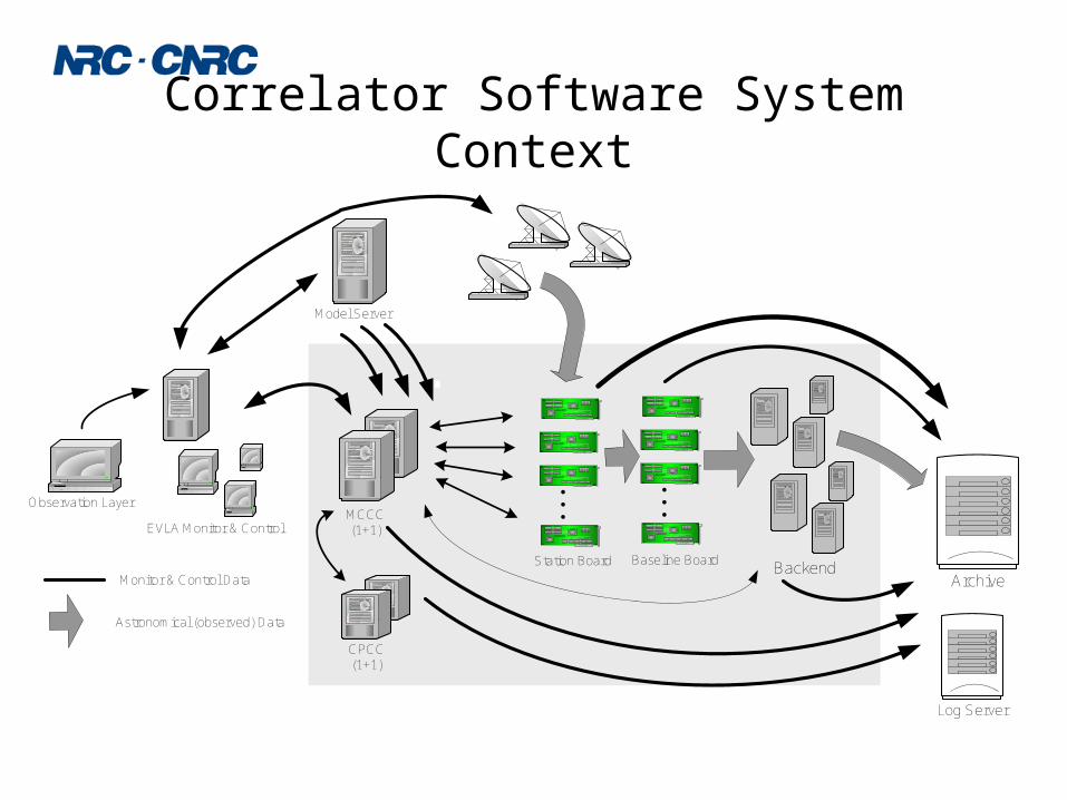
Correlator Software System Context
Archive
Model Server
Backend
Observation Layer
Log Server
. . .
. . .
Station Board Baseline Board
MCCC(1+1)
CPCC(1+1)
Monitor & Control Data
Astronomical (observed) Data
EVLA Monitor & Control

Correlator System GUI WIDAR Correlator - Top level system view (40 stations configuration)
Main
Rack 006 Rack 010
Rack 001 Rack 004Rack 003Rack 002 Rack 005
Rack 008 Rack 009
Rack 105 Rack 109
Rack 100 Rack 103Rack 102Rack 101
Rack 106
Rack 104
Rack 107 Rack 008
Rack 115
Rack 110 Rack 113Rack 112Rack 111 Rack 114
Rack 007
MCCC 1Active
MCCC 2Standby
CPCC 2Active
CPCC 1Standby
BootServer
Log Server
2007-123-09:30:00.000 In progress
2007-123:10:35:30.000
2007-123-09:45:34.000
2007-124:11:05:00.000
2007-122:23:30:00.000
2007-123:10:15:00.000
2007-123:09:30:00.000
In progress
Rejected
In progress
Accepted
In progress
Status
Test21
V01V23
V01V22
V014Q01
V021A90
V013Q23
V013Q22
Observation Start Time
Accepted
PowerSystems
Heatingand
Cooling
Details
01 4
02
03
04
05
05
06
4
4
2
2
2
001-0-0
001-0-4
001-1-0
001-1-4
002-0-0
002-0-2
002-0-4
001-0-1
001-0-5
001-1-1
001-1-5
002-0-1
002-0-3
002-0-5
Board2Board1#Boards
EVLA07
EVLA06
EVLA05
EVLA04
EVLA03
EVLA02
EVLA01
Antenna Quad
4
Backend
101-1-7 110-1-7
Running
2007-123-09:45:34.010 2007-123-09:45:34.010
TGM 1
Time 2
Time 1
Time 0
Status
Board
TGM 0
Running
Details
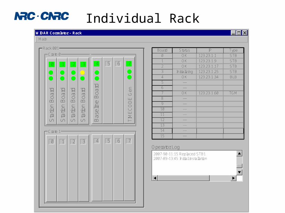
Individual RackWIDAR Correlator - Rack
Main
31 2
Crate 0
0 4 5 76
31 2
Crate 1
0 4 5 76
Rack 001S
tatio
n B
oard
Sta
tion
Boa
rd
Sta
tion
Boa
rd
Sta
tion
Boa
rd
Ba
selin
e B
oard
TIM
EC
OD
E G
en---15
14 ---
OK 123.23.1.60
---
---
---
---
---
---
TGM
TGM123.23.1.60
13
12
11
10
9
8
7
7 OK
OK 123.23.1.1
OK
OK
Initializing
OK
---
---
123.23.1.17
123.23.1.25
123.23.1.34
STB
STB
STB
STB
BLB
TypeIP
6
5
4
3
2
1
0
Board Status
123.23.1.9
2007-90-11:15 Replaced STB12007-89-13:45 Initial installation
Operator Log

Station Board Top LevelStation Board Rack: 1 Crate: 0 Slot: 5 Main
Screen FPGAsBoard
Timing
Block Diagram
Filter 0_11 Filter 0_13
Filter 0_17
FORM INPUT
DELAY A
DELAY B
Filter 0_01
VSI B
OUTPUT A
OUTPUT B
Filter 0_02
Filter 0_08
Filter 0_14
Filter 0_03
Filter 0_09
Filter 0_15
Filter 0_04
Filter 0_05
Filter 0_10
Filter 0_16
Filter 0_00
Filter 0_06
Filter 0_12
Filter 0_01 Filter 0_02
Filter 0_07
Filter 0_13
Filter 0_08
Filter 0_14
Filter 0_03
Filter 0_09
Filter 0_15
Filter 0_04 Filter 0_05
Filter 0_10
Filter 0_16
Filter 0_11
Filter 0_17
Filter 0_00
Filter 0_06
Filter 0_12
WBC MCB CFG
FPGA Cfg. Files FPGA Bit Files
Filter 0_07
INPUTFORM WBC
Delay 0
Delay 1
MCB CFG Timing
Filter 0_00 Filter 0_03Filter 0_02Filter 0_01
Filter 0_06
Filter 0_15
Filter 0_10
Filter 0_05
Filter0_00Filter0_00Filter0_00Filter0_00Filter0_00
VSI 0
Filter 0_14Filter 0_12
Filter 0_09Filter 0_08
Filter 0_04
Filter 1_08Filter 1_07Filter 1_06Filter 1_05Filter 1_04
Filter 1_03Filter 1_02Filter 1_01Filter 1_00
Output 0Filter 0_16
Output 1
Filter 1_17Filter 1_16Filter 1_15
Filter 1_14VSI 1
Filter 1_13Filter 1_12Filter 1_11Filter 1_10Filter 1_09
CRC Checking Setup
Refresh (on)
2Sec: OnceLED 1
LED 2
Run
HaltConfiguration File
running01 7 1 State:Board Serial # : 1234567890
/evla/widar/stb/cfg/test_1001
Design/Version/Release:

Filter Control GUI
Station Board Rack: 1 Crate: 0 Slot : 5 Filter 0_12
Screen Hardware
Register: Read:Write:
Read Write Write/Read
Read/Write Registers
Test Port TP0 TP1 TP2 TP3
33 5 17 255
Configuration
Refresh
Sec: Once
General
/evla/widar/stb/filter/cfg_01.xmlConfiguration File
FPGA Bit File /evla/widar/stb/filter/bit/abc Browse
Design/Revision/Version: running01 71 State:
Browse
Input delay calibration:
Status
Input delay adjust:
Delay Module Input:System clock:
Read/Write:
Reset status indicators
CRC
Auto
View Error Counts
Reset Error Counts
AInput: B
InOut
AOutput Enable:
Input Delay: 37 112Daisy Delay:
Time Interval : 1234567
Delay Model: External
Delay: 123456 Delay Rate: 0
Demux Factor:
Delay
0Data Input Rate: 15
Phase Factor: 0x4000
/evla/widar/stb/filter/s1prd/abcProduct File: Browse
Invalid Stretch Length :
Scale Factor : 1
Filter Delay :
Data Output Rate: 0
Number of Taps : 512
Stage 1
16
XBAR
32
/evla/widar/stb/filter/s2cof/abcCoefficient file Browse
Invalid Stretch Length :
Scale Factor : 1
Filter Delay :
Output Rate: 4
16
Calculation Rate: 0
32
Stage 2
Number of Taps 512
/evla/widar/stb/filter/s3cof/abcCoefficient file Browse
Invalid Stretch Length :
Scale Factor : 1
Filter Delay :
Output Rate: 8
16
Calculation Rate: 0
32
Stage 3
Number of Taps 512
/evla/widar/stb/filter/s4cof/abcCoefficient file Browse
Invalid Stretch Length :
Scale Factor : 1
Filter Delay :
Output Rate: 12
16
Calculation Rate: 0
32
Stage 4
Number of Taps 512
Format
Valids
on
313 312
Power off 12345 12344
Quantizer Clip Count
Quantizer State Count
1
4
Quantizer Power
RFI Detections
1234567
2
TEX Valids
TEX Sums
625
1234 252
Quantized State:
RFI Detect Level:
RFI Detect Length:
Auto -3
Select Data:
Quantizer Scaling:
Quantizer # Bits:
4
1
TEX Trig File
TEX Phase Model
TEX Phase:
TEX Phase Rate:
/evla/widar/stb/filter/fm/tex/trig/abc
External
0xFEDCBA9
0x12345678
Browse
0x17534
0x1234
4
256
Select Clip:
cos sin
on off
Output File: /evla/widar/stb/filter/fm/out/abc Browse
Clip Count 1234567
Sideband Flipper On
Histogram
VCI
1Input # bands:
128.0000Output band width (MHZ):
Output band center (MHz):
3Input # bits:
2048Input band width (MHz):
Mix:
4Output # bits:
192.0000000
1Input band:
Setup
/evla/widar/stb/filter/fm/out/abcResults file: Browse
Fbit:
Accumulation (interrupts): 100
Flip:
LSB:
Mixer Phase Model:
Phase Rate: 0xFEDCBA9
Phase:
Use mixer
0x00000000
/evla/widar/stb/filter/s2mix/abcMixer Trig File Browse
Mixer
External

P. Dewdney EVLA Review - May 2006 15N ational R esearch C ounci lC anada
C onsei l national de recherchesC anada
Correlator Software People• Sonja Vrcic (Penticton)
– Coordinates overall design and specification.– Virtual Correlator Interface (VCI) definition.– Master Correlator Control Computer (MCCC) S/W.
• Bruce Rowan (Socorro)– Correlator hardware control S/W (CMIB).
• Kevin Ryan (Socorro)– GUI development and hardware control S/W.
• Martin Pokorny (Socorro)– Correlator Backend software.
• Bryan Butler, Ken Sowinski, Barry Clark, Bill Sahr (Socorro)– Advisory capacity.

P. Dewdney EVLA Review - May 2006 16N ational R esearch C ounci lC anada
C onsei l national de recherchesC anada
Correlator-related Software Issues
• Correlator output: ALMA Science Data Model must be qualified for EVLA use.– On the surface ASDM looks all right in the sense that additions can be
made to meet EVLA requirements.– Was not necessarily designed with both telescopes in mind.– Is ALMA effort required and is it available?
• Preliminary plans to add “blocks” in the Correlator Back End (CBE).– Additional Ethernet Switch and output Fast Data Formatter
computer(s).– Formatting to ASDM spec’s will probably take place in the Fast Data
Formatter.– Details to be worked out.
• VCI Transport protocol is to be defined.• Potential unknown throughput issues could arise.

System Progress
• NRAO work on correlator room is progressing rapidly.• Design of overall room layout is complete.• Environmental specifications have been developed.
– Air flow & temperature: ~1700 cfm per rack, 15 oC.– ESD
• 90 nm devices used extensively (<1/1000 thickness of human hair)• Humidity specs.• Strict handling and servicing procedures.
– Air quality• ISO 14644-1 class 8 + MERV 13 filter.
• Racks– “Thermal prototypes” have been built and tested.– “Mechanical prototypes” ditto.– Preliminary fabrication plan is being developed.
• Preliminary installation plan is being developed.• Power plant specifications/RFP draft written for acquisition this fiscal
year (ends Mar 31/07).

Correlator Rack Layout1 Gbps
Ethernetto Backend
100/1000 MbpsEthernet M&C
M&CEthernetswitch
-48 VDCbreakerpanel
Up to 40, 4-wafer,1.024 Gbpscables from
station racks toFanout Boards.
-48 VDC,48VRET frompower plant
Up to 256, 4-wafer,
1.024 Gbpscables: Fanout-
to-BaselineBoards
FRONT
Raised floor
Rack pedestal
airflow
airflow

Correlator Room Layout48'-0"
Prim Bay
47
'-0"
2-cable 48VDC connects from each DCPDU breaker output to each rack
seperately.(24 cable pairs in a 32-Station correlator)
115VAC
Fiber Fiber
HV
AC
CW
UN
ITH
VA
C C
W U
NIT
SPARE - reservedHVAC 5th CW UNIT
(if req’d)
40-Station Expansionadds 2 Station racks
B
B
B
B
B
B
S40
S40
Station Racks(8)
BaselineRacks(16)
AC input for HVAC andlighting.
AC input, 50 kW, 56 kVA for backendcomputers, MCCC, CPCC, testoutlets
480 VAC, 3-phasedelta, 190 kW (211kVA) for 48 VDC plant
Sec
Bay
Battery String 1
Battery String 2
BE1
BE2
BE3
BE4
BE5
BE6
HVAC DXCOMPR UNIT
HVAC DXCOMPR UNIT
-48VDC Power Plant
Battery Strings
Backend Computers
B
B
B
B
B
B
B
B
S
S
S
S
B
B
S
S
S
S
SwitchRack
MCCC/CPCCRack
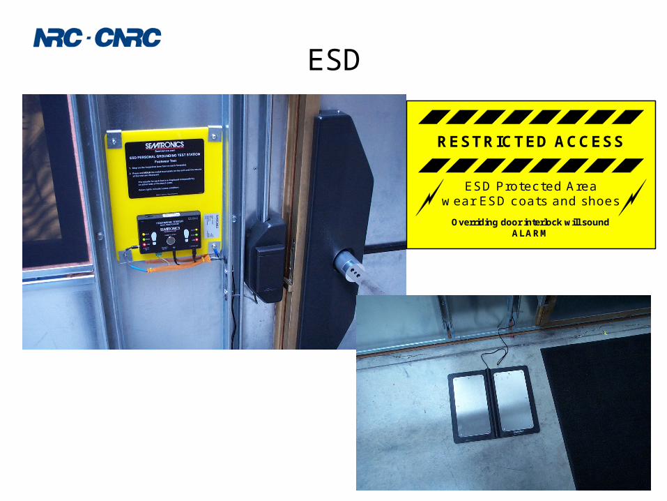
ESD
RESTRICTED ACCESS
Overriding door interlock will soundALARM
ESD Protected Areawear ESD coats and shoes
P. Dewdney EVLA Review - May 2006 21N ational R esearch C ounci lC anada
C onsei l national de recherchesC anada
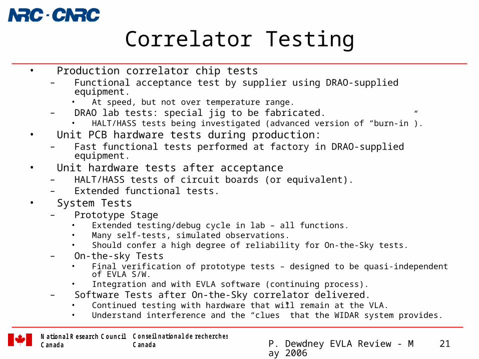
Correlator Testing• Production correlator chip tests
– Functional acceptance test by supplier using DRAO-supplied equipment.• At speed, but not over temperature range.
– DRAO lab tests: special jig to be fabricated.• HALT/HASS tests being investigated (advanced version of “burn-in”).
• Unit PCB hardware tests during production:– Fast functional tests performed at factory in DRAO-supplied equipment.
• Unit hardware tests after acceptance– HALT/HASS tests of circuit boards (or equivalent).– Extended functional tests.
• System Tests– Prototype Stage
• Extended testing/debug cycle in lab – all functions.• Many self-tests, simulated observations.• Should confer a high degree of reliability for On-the-Sky tests.
– On-the-sky Tests• Final verification of prototype tests – designed to be quasi-independent of EVLA S/W.• Integration and with EVLA software (continuing process).
– Software Tests after On-the-Sky correlator delivered.• Continued testing with hardware that will remain at the VLA.• Understand interference and the “clues” that the WIDAR system provides.

Test Configuration – Software View

On-the-Sky Test Setup
Fan Tray
-48 VDC Power Supply
Ethernet Switch
12Ucrate
Sta
tion
Bo
ard
Ba
selin
e B
oa
rd
Sta
tion
Bo
ard
Sta
tion
Bo
ard
Sta
tion
Bo
ard T
ime
cod
e B
oard
4' 5"
27"
Host ComputerBackendComputer
To NRAO network
1 phase: 170-264 VAC (30 A)
Host ComputerHost
Computer
“External Timecode” (fiber)
128 MHz CW, 0dBm
110 VAC, 15 A
From NRAOArray TimingReference
-48 VDC Breaker Panel

P. Dewdney EVLA Review - May 2006 24N ational R esearch C ounci lC anada
C onsei l national de recherchesC anada
Preliminary Installation Estimates(Note: Dates from Apr/06 Long Term Schedule)
• Q4-06/Q1-07 – power supply (-48 V DC) .– Procurement, installation, training.– 40 person-days of NRAO effort.
• Q3/Q4-07 – signal cabling.– Installation of inter-rack high-speed cabling.– 512 pre-fab cables, 3 different lengths; 24 pre-fab power monitor & control cables.– 52 person-days of NRAO effort.
• Q4-07/Q1-08 – Racks– 24 racks, pre-fabricated, tested in Penticton.– 24 person days of NRAO effort.
• Q1-08 – power cabling.– Two cable runs: To distribution panel; distribution panel-to-racks.– 20 person-days of NRAO effort.
• Q2-08 – control computers, M&C Ethernet– MCCC, CPCC, Ethernet switches, etc.– 120 VAC power required.– 8 person-days of NRAO effort.
• Q3-08 – Back-end computers and equipment.– Gbit Ethernet system– 20 person-days of NRAO effort.
• Q3-08/Q3-09 – Board installation and test.– Occasional NRAO effort.
EVLA Correlator Group

P. Dewdney EVLA Review - May 2006 26N ational R esearch C ounci lC anada
C onsei l national de recherchesC anada
Funding in Canada – No Change
Aug/03 – Canadian Treasury Board approval of submitted budget ($C 20M over 5 years).
• Most spending in $US.• But see risk factors.

Correlator Projected Spending Profile
EVLA Spending Profile
$-
$1,000,000.00
$2,000,000.00
$3,000,000.00
$4,000,000.00
$5,000,000.00
$6,000,000.00
$7,000,000.00
Fiscal Year
$C
Labour
Fabrication
Contracts
Equipment
Software
Miscellaneous
Travel
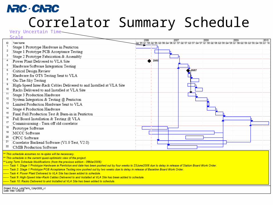
Correlator Summary ScheduleVery Uncertain Time Scale

Milestone Progress

P. Dewdney EVLA Review - May 2006 30N ational R esearch C ounci lC anada
C onsei l national de recherchesC anada
Project Management
• Schedule– Detailed schedule periodically updated.– Near-term (target) schedule updated weekly.– Long-term schedule discussed monthly, and
cross-checked against detailed schedule.• Budget
– Projections updated with schedule.• Bills of Materials (BOM’s)
– 1000’s of components.– Maintenance required.

P. Dewdney EVLA Review - May 2006 31N ational R esearch C ounci lC anada
C onsei l national de recherchesC anada
Correlator Documentation
• Master Document Tracking Spreadsheet Maintained at DRAO.
• 128 documents written so far, including “Memos”.
• Additional xxx documents with designations are anticipated.

P. Dewdney EVLA Review - May 2006 32N ational R esearch C ounci lC anada
C onsei l national de recherchesC anada
Principal Design Reviews
• Three Design Reviews:– Conceptual (CoDR – Nov, 2001)
• Review architecture and overall design.
– Preliminary (PDR – July, 2005)• Review detailed designs before prototypes.
– Critical (CDR)• Review system before “limited production” stage.
• Scheduled for Q2/Q3, 2007.

P. Dewdney EVLA Review - May 2006 33N ational R esearch C ounci lC anada
C onsei l national de recherchesC anada
Non-Technical Program Risks• Funding
– Original allotment of funds was over five years.
– NRC management was made aware in Aug/03 that this does not fit the project spending profile – they decided that internal cash management could deal with the problem.
– Will have to apply for an extension, which in the present climate presents a risk.
– Worst case is that project could be halted in April 2008.
• Schedule slippage?– Due to a slow start (already happened at the beginning).
– Concerns over procurement processes.• This risk is retired. Major procurement contracts are in place except for power supply.
– Technical progress slower than the deliberately aggressive initial schedule.
– “Re-spins” will present additional schedule risk.
• Inadequate contingency?– The contingency fractions are much smaller than most high-tech projects.
– Cost risk will be reduced quickly once prototypes are tested.
– Exchange-rate changes have been favourable to date.
• Inflation not being recognized in funding profile?– Inflation is a corrosive influence.

P. Dewdney EVLA Review - May 2006 34N ational R esearch C ounci lC anada
C onsei l national de recherchesC anada
Technical Program Risks• Technical risk is currently at a maximum
– Much design effort and prototype expenditure has taken place.
– Prototype hardware is being fabricated (or about to be fab’d), but not received/tested.
• But …– Considerable design effort expended to reduce technical risk.
• Finely divided testing schemes for circuit boards – every path can be checked independently.
• Correlator chip underwent an independent test and verification process, including a major simulation campaign after the “place-and-route” stage.
• A separate Design for Manufacturability (DFM) analysis done for circuit boards – results in a major reduction in risk.
• Formal system reliability analysis has been done, and will be updated.
• Funds and design effort has been expended to minimize technical risk.– We are optimistic and confident that technical risk is reasonably low.

P. Dewdney EVLA Review - May 2006 35N ational R esearch C ounci lC anada
C onsei l national de recherchesC anada
Descoping
• Have not reconsidered descoping options since the budget is currently “under control”.
• If the previously-mentioned program risks become imminent concerns, then de-scoping options will have to be revisited.

P. Dewdney EVLA Review - May 2006 36N ational R esearch C ounci lC anada
C onsei l national de recherchesC anada
Project Summary• Are we meeting the required schedule?
– We are sticking with the original delivery date, although there is some squeezing of activities
• Are we over budget at this stage?– Budget is slimly allocated, but we are not over budget.
• Are we planning to deliver on what we said we would do?– Yes, with minor improvements.
• What are the major risks at this stage?– Potential funding difficulty in 2008.– Technical risks should be reduced this year as prototypes are
tested.

End

text

P. Dewdney EVLA Review - May 2006 39N ational R esearch C ounci lC anada
C onsei l national de recherchesC anada
Status Requirements for the correlator software have been defined. Software architecture has been defined. Virtual Correlator Interface :
Content of the correlator input and output has been defined Format for the archived configuration and meta-data has been defined.– Format for backend and radar mode output data still needs to be defined and
will be discussed at this meeting. Requirements and Functional Specification (RFS) documents have been
developed for the major components: Generic CMIB software Backend and MCCC
• Rules for the mapping of the observation configuration into hardware configuration have been defined and are partially implemented (development effort postponed due to work on the software for the testing of the board prototypes).
P. Dewdney EVLA Review - May 2006 40N ational R esearch C ounci lC anada
C onsei l national de recherchesC anada
Software for the testing of the board prototypes I
Software requirements are defined in the document DRAO A25204N001.
Software development is well under way and we expect that we will be ready for the testing in May 2006.
CMIB communication infrastructure (IP and HTTP) has been defined and is already running on the PC104 board in the lab.
Low-level CMIB software: device drivers and module access handlers (MAHs) for Baseline Board and Station Board are being developed.
Backend:
Rudimentary (prototype) implementation of the Backend software is available.
Basic Monitor & Control interface (Command Line Interface) is provided.
User Manual that describes the current implementation is available.
– Some work will be required on output data formatting.
– Additional work is required to obtain the required products (TBD).

P. Dewdney EVLA Review - May 2006 41N ational R esearch C ounci lC anada
C onsei l national de recherchesC anada
Software for the testing of the board prototypes (II) GUI Interfaces for the Baseline Board and Station Board are in the final
phase of development. GUI interface for the graphical representation of the correlator output:
The first version of RFS has been released, s/w development has started.
System-level interface for the prototype testing is being defined, implementation will start in May 2006.
So far, Monitor & Control function for the following subsystems is not integrated:– Station Board Fiber Optic Receiver Module (FORM)– Backend– Model Server (not part of the correlator, will be needed for on-the-sky
testing)

text

P. Dewdney EVLA Review - May 2006 43N ational R esearch C ounci lC anada
C onsei l national de recherchesC anada
GUI Test Software Status Top level GUI and configuration of observation – design proposal Baseline Board - to be completed in April 2006 Station Board - to be completed in April 2006 TIMECODE Generator (test version) – Completed Phasing Board – board development postponed Graphical representation of the correlator output – design completed Monitor & Control functionality for the following subsystems has not
been integrated:– Station Board Fiber Optic Receiver Module (FORM)– Backend– Model Server (not part of the correlator, will be needed for on-the-sky testing)
• FORM and Backend provide each own CLI. – To allow for automatic re-configuration, CLI commands could be specified in
the text file and added to the observation file.