ozone protection, climate change, energy efficiency
TRANSCRIPT
Supplemento 1 al N° 321 (N° 7-2008) - Sped. a. p. - 70% - Fil. Alessandria - Dir. resp. E. Buoni - Via Alessandria, 12 - Tel. 0142.453684 - 15033 Casale Monferrato - ITALY
UNDER THE AUSPICES OF THE ITALIAN MINISTRY OF THE ENVIRONMENT
refrigeration and air conditioning
special international issue
ForewordsAchim Steiner - Executive Director of the United Nations Environment Programme, Stefania Prestigiacomo - Italian Minister of Environment
Working together with the major experts towards “the future of refrigeration”:XIII European ConferenceMarco Buoni - Secretary Associazione dei Tecnici Italiani del Freddo - ATFDidier Coulomb - Director International Institute of Refrigeration - IIRRajendra Shende - Head, OzonAction, UNEP DTIE, Paris
Convenient Opportunity to Address an Inconvenient TruthInterview with Rajendra Shende - Head, OzonAction, UNEP DTIE, Paris
Refrigeration for Sustainable Development. History and ChallengesDidier Coulomb - Director International Institute of RefrigerationIntroduction - A 100-year history - refrigeration is necessary for mankind
Trends in Commercial RefrigerationPietro Asinari, Marco Masoero, Michele Calì - Department of Energetics DENER -Politecnico di Torino - ItalyIntroduction - Technological and design innovation - Commercial refrigeration goes aboard- Research projects - Conclusion
Heat pumps using natural working fluids: an environmental friendly solutionAlberto Cavallini, Davide Del Col, Claudio ZilioDipartimento di Fisica Tecnica - University of PadovaIntroduction - Carbon dioxide transcritical heat pumps - Propane heat pumps - Summary
Ground-source heat pumpsHermann Halozan - Institute of Thermal Engineering, Graz University of technologyIntroduction - Heating-only systems - Heating and cooling systems - Summary
Phase-out of HCFCs: impact on air-conditioning and refrigeration systemsoperating on R22 Patrick Antoine - President Association Française du Froid AFFGuy-Noel Dupré - UniclimaTo carry on using R22 in existing equipment - Replacement using HFCs - Replacement ofa refrigeration plant - Conclusion
Refrigerant Use and Emission Reduction in the U.S.: 2008 Mark Menzer, Xudong Wang - AHRI Air-Conditioning, Heating and Refrigeration InstituteAlternative refrigerants and systems - Activities to minimize emissions - Future activities
Development Trends of Ammonia Refrigeration Technology Yang Yifan, Hu Wangyang - Chinese Association of RefrigerationIntroduction - Main Characteristics - Present status - development trends
Solar cooling with small-size absorption chillers: different solutions for summerair conditioning Francesco Asdrubali, Giorgio Baldinelli, Andrea Presciutti - University of Perugia -Department of Industrial Engineering Section of Applied Physics - ItalyIntroduction - Driving absorption machines with solar energy - Investigated small-sizeabsorption chillers-Comparative analysis-First results of an experimental plant- Conclusion
Solar Cooling in the Unit for Development of Solar EquipmentsA. Chikouche, S. El Metnani, A. Benhabiles, B. Abbad - Bou-Ismail, Wilaya de Tipaza -AlgeriaIntroduction - Characterization of a photovoltaic driven domestic refrigerator - Simulation ofan air dehumidifier based on a vapour compression cycle
Sustainable RefrigerationPaul Homsy - NestléRefrigeration is essential for the food industry - Setting the trend in industrial refrigeration -Developing sustainable solutions for smaller refrigeration units - Confirming the policy onthe use of natural refrigerants
Magnetic Refrigeration at Room TemperaturePeter Egolf - University of Applied Sciences of Western SwitzerlandRonald Rosensweig - Chaires Internationales de Recherche Blaise PascalIntroduction - The magnetocaloric effect - Processes of magnetic refrigeration -magnetocaloric materials and their properties - Magnetothermodynamic machines -Advantages and drawbacks - Possibile future applications - Conclusion
3
4
6
8
15
19
22
25
28
31
34
39
44
45
Publishing manager:Enrico [email protected]
Editor:M.C. Guaschino
Editorial:Industria & Formazionevia Alessandria, 1215033 Casale MonferratoPhone +39 0142 452403Fax1 +39 0142 341009Fax2 +39 0142 452471
Advertisement:Phone +39 0142 453684
Publisher:A.Vi. Casale MonferratoPublished by:A. Valterza - Casale Monferrato
www.centrogalileo.itwebsite of the activity
www.associazioneATF.orgwebsite of the Italian Associationof Refrigeration Technicians
About the picture on the cover:as ISI 2006 this image of AchillIsland, off the most North-Westerlypoint of Ireland, illustrates: - Ozone protection
the sky: the blue sky contains ourEarthʼs ozone shield.
- Climate changethe sea: higher temperaturescould lead to sea level rise andextreme weather events.
- Energy efficiencythe waves: renewable energysources such as waves arewaiting to be harnessed.
Contents
Supplemento 1 al N° 321 (N° 7-2008) -Periodico mensile - Autorizzazione delTribunale di Casale M. n. 123 del13.6.1977 - Spedizione in a. p. - 70% -Filiale di Alessandria - ITALY.
This magazine has been produced withpaper E.C.F. (Elementary clorine Free)
On theleftpictureof thecoverISI 2006
3
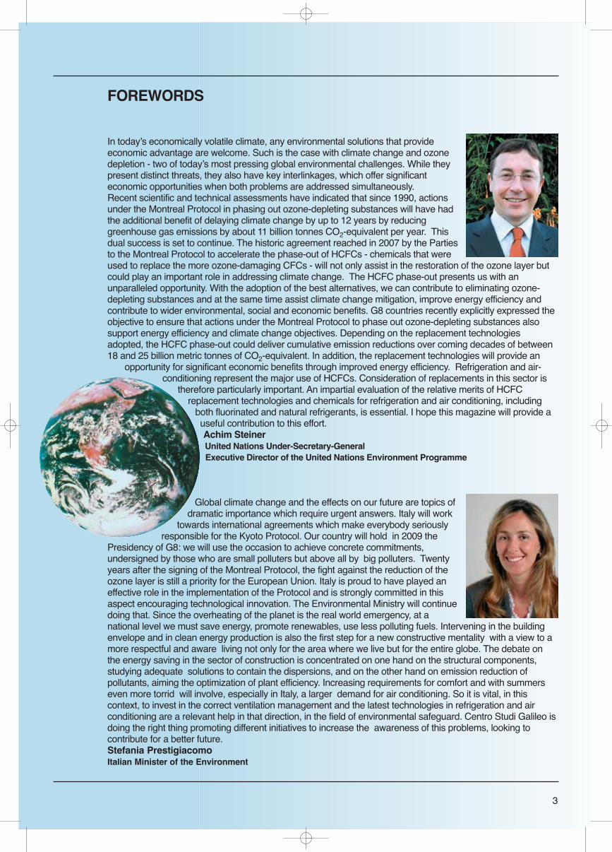
FOREWORDS
In todayʼs economically volatile climate, any environmental solutions that provideeconomic advantage are welcome. Such is the case with climate change and ozonedepletion - two of todayʼs most pressing global environmental challenges. While theypresent distinct threats, they also have key interlinkages, which offer significanteconomic opportunities when both problems are addressed simultaneously.Recent scientific and technical assessments have indicated that since 1990, actionsunder the Montreal Protocol in phasing out ozone-depleting substances will have hadthe additional benefit of delaying climate change by up to 12 years by reducinggreenhouse gas emissions by about 11 billion tonnes CO2-equivalent per year. Thisdual success is set to continue. The historic agreement reached in 2007 by the Partiesto the Montreal Protocol to accelerate the phase-out of HCFCs - chemicals that wereused to replace the more ozone-damaging CFCs - will not only assist in the restoration of the ozone layer butcould play an important role in addressing climate change. The HCFC phase-out presents us with anunparalleled opportunity. With the adoption of the best alternatives, we can contribute to eliminating ozone-depleting substances and at the same time assist climate change mitigation, improve energy efficiency andcontribute to wider environmental, social and economic benefits. G8 countries recently explicitly expressed theobjective to ensure that actions under the Montreal Protocol to phase out ozone-depleting substances alsosupport energy efficiency and climate change objectives. Depending on the replacement technologiesadopted, the HCFC phase-out could deliver cumulative emission reductions over coming decades of between18 and 25 billion metric tonnes of CO2-equivalent. In addition, the replacement technologies will provide an
opportunity for significant economic benefits through improved energy efficiency. Refrigeration and air-conditioning represent the major use of HCFCs. Consideration of replacements in this sector is
therefore particularly important. An impartial evaluation of the relative merits of HCFCreplacement technologies and chemicals for refrigeration and air conditioning, including
both fluorinated and natural refrigerants, is essential. I hope this magazine will provide auseful contribution to this effort.Achim SteinerUnited Nations Under-Secretary-GeneralExecutive Director of the United Nations Environment Programme
Global climate change and the effects on our future are topics ofdramatic importance which require urgent answers. Italy will work
towards international agreements which make everybody seriouslyresponsible for the Kyoto Protocol. Our country will hold in 2009 the
Presidency of G8: we will use the occasion to achieve concrete commitments,undersigned by those who are small polluters but above all by big polluters. Twentyyears after the signing of the Montreal Protocol, the fight against the reduction of theozone layer is still a priority for the European Union. Italy is proud to have played aneffective role in the implementation of the Protocol and is strongly committed in thisaspect encouraging technological innovation. The Environmental Ministry will continuedoing that. Since the overheating of the planet is the real world emergency, at anational level we must save energy, promote renewables, use less polluting fuels. Intervening in the buildingenvelope and in clean energy production is also the first step for a new constructive mentality with a view to amore respectful and aware living not only for the area where we live but for the entire globe. The debate onthe energy saving in the sector of construction is concentrated on one hand on the structural components,studying adequate solutions to contain the dispersions, and on the other hand on emission reduction ofpollutants, aiming the optimization of plant efficiency. Increasing requirements for comfort and with summerseven more torrid will involve, especially in Italy, a larger demand for air conditioning. So it is vital, in thiscontext, to invest in the correct ventilation management and the latest technologies in refrigeration and airconditioning are a relevant help in that direction, in the field of environmental safeguard. Centro Studi Galileo isdoing the right thing promoting different initiatives to increase the awareness of this problems, looking tocontribute for a better future.Stefania PrestigiacomoItalian Minister of the Environment
4
INTRODUCTION
The second edition of the International Special Issue 2008 takes its cue from the first edition which was a great success.It was delivered at New Delhiʼs UN Summit of Montreal Protocol to Head of States and Ministers (2006) in order to showthe environmental problems linked to refrigeration and air conditioning.The previous issue has been also delivered to various other UN summits including Nairobiʼs 2006 and Baliʼs 2007Conferences of Kyoto Protocol and the XII European Conference of Centro Studi Galileo.As in 2006 and 2007, the new ISI 2008 will be distributed also to the worldwide operators of refrigeration and airconditioning connected with the United Nations and the International Institute of Refrigeration and the 13th EuropeanConference of Centro Studi Galileo and of Associazione dei Tecnici del Freddo in which all the major associations andWorld Organizations will also participate.
LATEST REFRIGERATION AND AIR CONDITIONING TECHNOLOGIES IN RELATION TO THE ENVIRONMENT
The International Special Issue first edition 2006 was born with the purpose of showing in a popular way theenvironmental problems connected with refrigeration and air conditioning.Refrigeration and Air conditioning are nowadays fundamental elements in the everyday life of human beings -
technologies which we cannot do without. They have also been veryimportant for the economic expansion that we have seen in the lastcentury: the International Institute of Refrigeration (IIR) as well asvarious national associations of refrigeration (AFF,...) have launched in2008 the “Refrigeration Year”. They will be celebrating theircentenaries.Refrigeration has permitted the transportation and preservation offood in every part of the world avoiding food waste. Air conditioninghas permitted comfortable conditions of living and working both inseasons and countries particularly warm and humid.Refrigeration has been the key driver of Montreal Protocol relatedachievements in the addressing of ozone depletion. By phasing outCFCs, the impact of the Montreal Protocol has been 5 times aseffective as that of the Kyoto Protocol in terms of mitigation of globalwarming: refrigeration is already within a sustainable developmentframework.These technologies, essential for humanity, are however still importantfactors which have to be controlled for the safeguarding of theenvironment. ISI 2006 had explained the problems connected withrefrigerants CFC, HCFC - responsible both for Ozone Layer Depletionand Climate Change. Present HFCs, which often replace CFCs andHCFCs, have a high global warming potential. We must search othersolutions.This second edition has evolved naturally and it is realized by UNEP,IIR and CSG underlining which are the alternative technologies toavoid environmental problems in the future.
ISI 2008 is centred on the latest exploitable and available technologies to replace HCFCs in the area of Ozone protectionand Climate Change prevention in refrigeration and air conditioning taking into account energy problems, theenvironment, climate change and energy efficiency. It is focused on solutions like natural refrigerants, absorptionsystems, solar cooling, magnetic refrigeration with practical case and specific examples.In this magazine the major associations, institutes and worldwide organizations describe the above subjects in acomplete manner, explaining the advantages of the technologies and how those, in the different regions of the world,
Editorial
Working together with the major experts towards“the future of refrigeration”: XIII European Conference
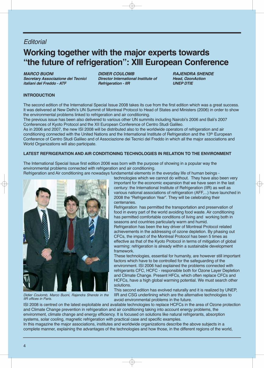
Didier Coulomb, Marco Buoni, Rajendra Shende in theIIR offices in Paris.
MARCO BUONISecretary Associazione dei Tecniciitaliani del Freddo - ATF
DIDIER COULOMBDirector International Institute ofRefrigeration - IIR
RAJENDRA SHENDEHead, OzonActionUNEP DTIE
5
could be helpful to improve the environment and tosolve the problems connected to it.Each application of refrigeration needs adaptedsolutions. It was impossible to cite all of them, eitherbecause the application is very specific, eitherbecause solutions are very soon emerging, as it is thecase in mobile air conditioning: the latest Europeanregulation impose a refrigerant with a Global WarmingPotential below 150. Two technologies are nowcompeting: CO2 as a refrigerant and new syntheticrefrigerants.
XIII EUROPEAN CONFERENCE UNEP-IIR-CSG
In the matter of the latest technologies in refrigerationand air conditioning Centro Studi Galileo, editor of ISI2008, organizes every 2 years a Europeanconference. The next XIII UNEP-IIR-CSG European Conference,will be held in the Politecnico of Milano and it will seethe participation, besides the authors of the ISI 2008,of all the major international experts in HVACR sector.
Among the international Associations that collaborate in the conference XIII European Conference UNEP-IIR-CSGthere are:- ATF (Association of Italian Technicians of Refrigeration) - AREA (Air Conditioning and Refrigeration European Association),- AFF (French Association of Refrigeration),- ASHRAE (American Society Heating RefrigerationAir conditioning Engineers)- AICVF (the French Association of Engineers of theAir conditioning, Ventilation and Refrigeration), andmany more which write on this issue.These associations / institutes are among the mostimportant in the refrigeration and air conditioning fieldand most of them have contributed to this specialinternational issue.The International Institute of Refrigeration alsoorganizes numerous international conferences onvarious subjects dealing with new technologicaldevelopments in the refrigeration fields:see www.iifiir.org
IMPORTANCE OF TRAINING
The role of Centro Studi Galileo, the InternationalInstitute of Refrigeration and the United NationsEnvironment Programme (www.unep.fr/ozonaction) isnot only to organize scientific and technical conferences. It is also necessary to write courses and to organize trainingsfor technicians and engineers who will build new plants with a better environmental impact and who have to properlymaintain plants, without refrigerant leakages.The IIR publishes several courses: see www.iifiir.org and organizes courses in various countries on a case by case basis.Centro Studi Galileo organizes about 200 technical seminars and trainings for technicians all over Italy. These take placein different training sites and in the main Italian Universities, teaching every year more than 2.000 attendants theprocedure to have a perfect maintenance, installation and design, in order to optimize their work and consequentially toreduce energy efficiency and environmental dangers.We would thank all the authors of the articles for the time they have dedicated to write this brochure. They are membersof various organizations, universities and private companies, which work in the refrigeration fields in order to mitigate theimpacts on environment: it is a collective work.We also would thank the Italian Minister of Environment Stefania Prestigiacomo for her support, which has allowed us topublish this document. Italy thus contributes to a better global environment.
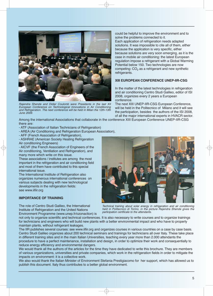
Rajendra Shende and Didier Coulomb were Presidents in the last XIIEuropean Conference on Technological Innovations in Air Conditioningand Refrigeration. The next conference will be held in Milan the 12th-13thJune 2009.
Technical training about solar energy in refrigeration and air conditioningheld in Politecnico di Torino, in the picture Rajendra Shende gives theparticipation certificate to the attendants.
6
Rajendra Shende, Head ofOzonAction, of United NationsEnvironment Programme (UNEP)and one who for more than adecade, promoted ʻOne solution forTwo Protocols ̓talks here withMarco Buoni, Head of the editorialteam. The two Protocols referencedare the Montreal Protocol and theKyoto Protocol. Early on, many ofthe substitutes of Ozone DepletingSubstances were also GreenhouseGases, more dangerous thancarbon dioxide. For example, HFCssubstituted CFCs and they were anacceptable solution under theMontreal Protocol. But emissions ofHFCs were controlled under theKyoto Treaty. The internationalregime of environmentalnegotiations has taken time toresolve this dilemma. In September2007, 191 Parties to the MontrealProtocol took another momentousdecision to advance phase out ofHCFCs which presents anunparallel opportunity to contributeto prevention of Climate Change.The global environmentalgovernance scenario is changingfast: Interview follows.
Why is the accelerated HCFC phaseout in 2007 so important for theworld community?HCFCs are mild Ozone DepletingSubstances as compared to CFCs.Their ODS potential is only about 5 %of that of CFCs. Hence, the phase outdates was agreed 2040 - a very longperiod indeed! Literally 5 generations
can watch the slow phase out ofHCFCs. Obviously, the message theindustry and the consumers got was:there is no urgency to act in getting ridof HCFCs. In fact, in a number ofcases, HCFCs are used as substitutesfor CFCs. The result of such ʻglacierʼspeed of the HCFC the phase out wasthe ʻjet ̓speed in the rise of its produc-tion and consumption. Between 1989and 1996 the consumption doubled. Itdoubled again from 1996 to 1999. Andit doubled once again from 1999 to2004. The best guess is it must havedoubled once more from 2004 to 2008.It is estimated that in year 2010 it couldcross 800,000 tones per year. Imagine that when shares of a compa-ny are rising steeply, the managementof the company decides to stop manu-facturing. This is what happened in thecase of HCFCs in the year 2007, whenthe Parties to the Montreal Protocoltook the decision to accelerate thephase out.
Why you think that such a decisionwas taken in 2007? Why was it notdone earlier?It was a question of priority. TheMontreal Protocol is really the first inter-national environmental treaty with atime-bound obligation accepted by 193Governments in the world. Hence,Parties considered that in eliminating97 Ozone Depleting Substances (14 ofwhich are the majors in terms of vol-umes consuming ODP of the sub-stances) there is a need to get rid ofthose ODS first which have a higherODP. HCFCs have a much lower ODP
ranging from 0.1 to 0.02 as comparedto CFCs and Halons which have anODP ranging from 1 to 10. Thereforethe phase out schedule of HCFCs firstagreed in 1992 in Copenhagen wasmuch slower and longer term, i.e. by2040. This was really a long period,almost equivalent to a generation gap! However, as the world progressed inimplementing the Montreal Protocol,the success of the phase out of CFCsprompted two considerations, first: itwas evident to policy makers that get-ting HCFCs phased out earlier than2040 is important as their consumptionwas going steeply, second: there wereclear climate benefits to avail. Thesewere low hanging fruits to take benefitfrom. The scientific paper by Mr G.Velders (The importance of theMontreal Protocol in protecting climate,20 March 2007) very clearly demon-strated the climate benefits that alreadyaccrued by global phase out of morethan 95 % of ODS. This paper, as wellas IPCC/ TEAP report, i.e. SpecialReport on Safeguarding Ozone Layerand Climate System, analytically putforward the future climate benefits till2015 and beyond by phasing out. Thegovernments reacted to these scientificand technical findings. All this explains that time was ripe totake a decision of accelerated phaseout of HCFCs.
If ODP of HCFCs is only 5 % ofCFCs, is the world really going tobenefit by its accelerated phase outof HCFCs? How?It is evident therefore that HCFCs
Special interview
“Convenient Opportunityto Address an Inconvenient Truth”
RAJENDRA SHENDE
Head, OzonAction, UNEP DTIE, Paris
7
phase out helps ozone layer protec-tion as well as climate change, butmore than that it helps the economy.It also contributes to energy security.These far wider environmental, socialand economic benefits arising out ofHCFC phase out have not been fullyrecognized. Accelerated phase out ofHCFCs offers the world “quick wins” inaddition to mitigating climate changeand builds confidence that a new inter-national regime on GHG emissionscan be agreed before the first phaseof Kyoto Protocol expires in 2012.Climate benefits of accelerated phaseout of HCFCs comes from:- Reduction of emission of HCFCs fromthe equipment (e.g. refrigeration equip-ment) and from foams which are blownwith HCFCs by using best prac-tices - Reduction in production andconsumption of HCFCs byadopting lower GWP alterna-tives to HCFCs- Improving in energy efficiencyof the equipment using alterna-tives to HCFCs.- Destroying HCFCs at the endof life.Frankly, the decision of Partiesto the Montreal Protocol toaccelerate phase out of HCFCsis going to benefit climatechange regime more. The ODPof HCFCs is 20 times lower thanCFCs, but the GWP of HCFC is2000 tons more than that ofCO2. Phase out of HCFCs wouldadvance the recovery of ozone layer byabout 10 years, whereas it would delayclimate change by many more years.Accelerated phase out of HCFCs couldreduce emissions by about 18 GT CO2-eq. between 2010 and 2050. This issignificant if we compare that thereduction expected from KyotoProtocol between 2008 - 2012 is 5 GTCO2-eq. If zero or low GWP substitutetechnologies are adopted by countriesto replace HCFC usage this cumulativeemission reduction is certainly feasible.There is also an opportunity to gainadditional climate benefits throughimproved energy efficiency in appli-ances including room air conditionersusing HCFCs. Such measures wouldtake the cumulative climate advantageto equivalent of about 38 GT CO2-eq.For example, based on the IEAʼs calcu-
lations related to energy efficiency ofroom air conditioners in Chinaʼs warmprovinces, if energy efficiency levels areachieved as much as those achievedfor Japanese room air conditioners, thereduction in total power requirementcould be between 15 - 30%. If calculat-ed over the next 15 years, this couldamount to 260 TWh which is equivalentto output from 50 average power plantsof 5 TWh capacity each.
What are the steps that UNEPʼsOzonAction is proposing to enabledeveloping countries to take on cli-mate benefits from acceleratedphase out of HCFCs?The UNEP OzonAction strategy toenable 145 developing countries to
avail this extraordinary opportunity.There is now global, regional andnational infrastructure that has beenstrengthened and capacity built in thedeveloping countries as a result ofphase out of HCFCs to take this issuehead on. It is true that in terms of sheer volume,the amount of HCFCs that developingcountries have to phase out by 2030 isfar larger than the CFCs that they willhave phased-out by 2010. Howeverthey now have ʻhands-on ̓ experiencein phasing out more than 90% of theCFCs and some other ODSs, andmore than that they know that whileimplementing the Montreal Protocol,this is contributing to environmentaland development goals.UNEP OzonAction has an overallmandate to enable countries to meetcompliance with the Montreal Protocol
through capacity building and technol-ogy support. While implementing thismandate, UNEP will utilise the lessonslearned over the last 20 years in work-ing with the developing countriesthrough delivery of its integrated serv-ices, such as information exchange ontechnologies and policies, regionalnetworking of the National OzoneUnits, training of the technicians, poli-cy makers and customs and monitor-ing officers. The foundation of this exercise will belaid by developing the HCFC Phase-out Management Plan - HPMP-througha participatory approach. UNEPOzonAction has gained experiencefrom developing the Country Program-mes in more than 100 countries. Based
on the lessons-learned, UNEPhas developed a guidancemanual for the development ofHPMPs which will play a keyrole in developing the HPMPs innearly 60 countries, includingIndia and China. Through its regional networkingand thematic workshops, UNEPwill disseminate the technologyinformation and that while con-tributing to solving theses twoglobal problems, countries haveunparallel opportunity to getnotational benefits by reducingenergy consumption.Communicating the multipleadvantages at the global andlocal level will be the key ele-
ment of UNEP strategy. UNEPʼs web-based HCFC Help Center will becomea hub for the information on alterna-tive technologies and policies particu-larly adapted to low or zero GWP andof improved energy efficiency.What I would like to state on behalf ofUNEP OzonAction is: The second phase of the MontrealProtocol has dawned upon us. Themorning of the second phase comeswith a golden opportunity to simulta-neous protect the ozone layer, curvethe GHG emissions and reap eco-nomical and developmental benefitsfor long-term sustainability.This second phase of the MontrealProtocol provides very strong confi-dence-building ambience for thenegotiations leading towards the sec-ond phase of the Kyoto Protocol.
●
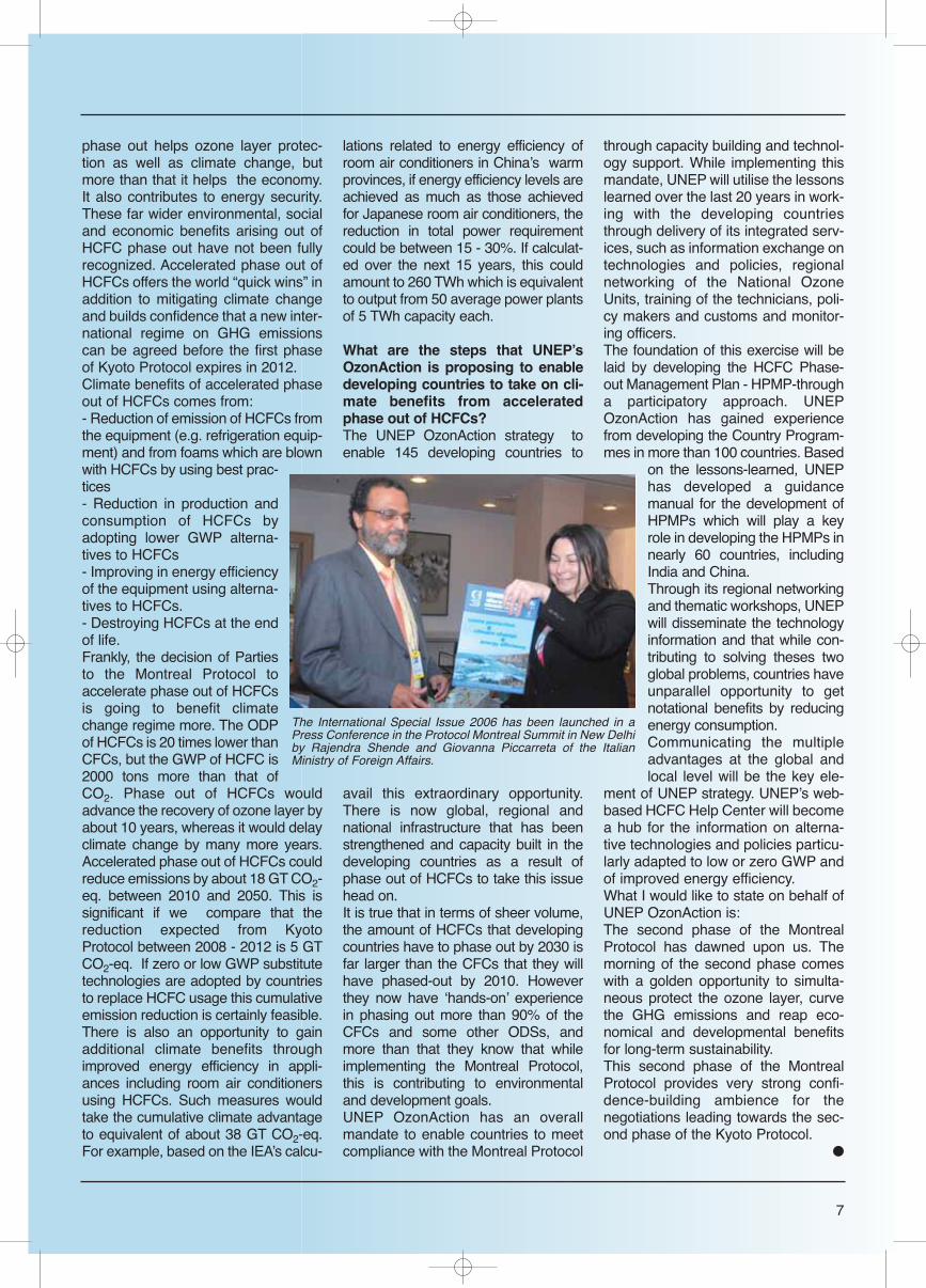
The International Special Issue 2006 has been launched in aPress Conference in the Protocol Montreal Summit in New Delhiby Rajendra Shende and Giovanna Piccarreta of the ItalianMinistry of Foreign Affairs.
8
INTRODUCTION
Refrigeration, including air condi-tioning, is now at the heart of globalenvironmental challenges, becauseof its impacts on the ozone layerand on global warming.Recent and probably future meas-ures will need many changes in thissector. However, refrigeration isnecessary for life and the aim is toensure that this sector will continueto expand, but in a sustainable way.A historical perspective is neces-sary to understand the former evo-lution of the needs of refrigerationand of the various technologies thathave been used, in order to antici-pate future evolutions.
A 100-YEAR HISTORY
Man has always needed cold (1):preservation and transport of food-stuffs thanks to snow or natural icehave been reported in the RomanEmpire; ice was used as a means oftransport (marble in the Forbidden Cityin China) or as a construction materialfor houses (igloos in Greenland)...Because temperature is a magnitudeand a key variable in physics, chem-istry and biology, and characterizes thestate of matter and liquid, solid andgaseous phases, which is vital to all liv-ing beings: each living being (bacteria,plant, animal) has a temperature rangewithin which it can live; each pathogencan grow, survive or not according tothe temperature.Foodstuffs are thus chilled or frozen toensure that they are healthy and toprevent the growth of pathogens.The 19th century was the key century.This was a great century for scientificand technical discoveries, particularlyin the field of thermodynamics. TheIndustrial Revolution took place in the19th century and required refrigera-tion: dairy products, meat, brew-eries.... And of course ice making. Theadvent of railways and steamshipsboosted trade in natural ice fromScandinavia and Canada, but suppli-ers could not keep pace with the grow-ing demand. Furthermore, rising con-cern about the sawing of blocks of icefrom polluted rivers and lakes gaveextra impetus to the development ofmachines that could manufactureclean artificial ice. These machines
have been developed since the mid-dle of the 19th century. There weretwo developmental axes: supply andtransport of foodstuffs (first boat totransport meat between SouthAmerica and Europe in 1876, Le frig-orifique); mastering matter throughgas liquefaction (hydrogen, helium,...)with applications developed during the20th century (health, space, energysupply and transport...).In 1908, the First InternationalCongress of Refrigeration took placein Paris, France, with about 5000 par-ticipants of 40 countries. Representa-tives from the worlds of science, com-merce, industry and governmentexchanged views on low tempera-tures, refrigeration technology, food,applications of artificial cold in tradeand industry, and legislative issues.The Congress culminated in the found-ing of the International Association ofRefrigeration, which became theInternational Institute of Refrigeration(IIR), an intergovernmental organiza-tion, in 1920. Throughout the 20th century, thisinteraction between science andindustry led to the providing of goodsand the setting up of services vital tomankind:- cryogenics: air separation for medicaluses (cryosurgery, anaesthesia); petro-chemical refining, steel production.. ;space propulsion fuels, superconduc-tivity for large research instruments,energy (thermonuclear fusion...), med-ical applications (scanners..), transportand distribution of natural gas or hydro-gen, manufacturing of semi-conduc-
Refrigeration for sustainabledevelopment.History and challenges
DIDIER COULOMB
Director International Institute of Refrigeration - IIR
The International Institute ofRefrigeration (IIR) is anindependent intergovernmentalscience-based organization whichpromotes knowledge ofrefrigeration and associatedtechnologies that improve qualityof life in a cost-effective andenvironmentally sustainablemanner including:- Food quality and safety fromfarm to consumer- Comfort in homes andcommercial buildings- Health products and services- Cryology- Energy efficiency- Use of non-ozone depleting andlow global warming refrigerants ina safe manner.Web site: www.iifiir.org
tors, sequestration of CO2, conserva-tion of species...- other health uses: preservation ofcells, tissues, organs, embryos... sur-gery and operating theatres, manufac-turing and transport of drugs, vac-cines...- air conditioning: vehicles, living areas,integrated systems (heating and cool-ing) with heat pumps, offices and facto-ries, particularly in hot climates but alsofor technologies (electronic compo-nents, computer technology, biotech-nology)...- food: manufacturing (texturation, for-mulation, freeze-drying, fermentation,concentration and separation), stor-age, transport, commercialization.- public works, leisure activities...Despite various other technologiestested in the 19th century, most of thetechnologies used in the 20th centuryand today are vapour-compressionsystems, which use refrigerants. Manyrefrigerants were also tested. No sin-gle refrigerant was perfect (flammabil-ity, toxicity, efficiency...). No singlerefrigerant could be used in all condi-tions, for all uses with all kinds ofmaterials (corrosion...). Two types ofrefrigerants dominated the 20th centu-ry: ammonia, for large industrial sys-tems (food processing and storage)because of its efficiency; chlorofluoro-carbons (CFCs) and little later hydrochlorofluorocarbons because of safetyand durability, for other applications.Because of the environmental impactsof these refrigerants, discovered in the1970s, changes had to be implement-ed (cf III).
REFRIGERATION IS NECESSARYFOR MANKIND
Uses of refrigeration are numerous.However, health issues are, with envi-ronmental issues, the main challengesfor the 21st century. Because of therole of refrigeration in the preservationof health, it is necessary to emphasizekey figures.Uses of refrigeration for hospitals orhealth products have already beenpresented (I). But the main use ofrefrigeration is still the preservation offoodstuffs.
As crystallized by Robert Heap(2)“Food safety and food security arevery important. Deficiencies in thesemay result in illness or death, in manypeople being undernourished, in valu-able foodstuffs being lost, and in prob-lems of proper disposal of unfit food.There is increasing interest in energyuse and carbon footprints; food wast-ed through poor food safety measuresresults in waste of the energy used infood production, transport, and stor-age.” According to the FAO, more than 800million people worldwide are under-nourished, mostly in Asia and Africa.“Until now, most measures to over-come under nourishment have con-centrated on increasing agriculturaloutput. But it is also important toreduce losses, and here refrigerationcan help. Out of a worldwide agricul-tural output of 5500 million tonnes(including fish and seafood), only anestimated 400 million tonnes are
refrigerated (i.e. chilled or frozen). TheIIR(3) estimates that 1800 milliontonnes would benefit from refrigeratedstorage or transport. The developmentof better-refrigerated cold chains cantherefore be an important aid to secu-rity of food supplies. Freezing foodenables it to be kept safely for longperiods. Foodstuffs last longer forbeing chilled, but still have a limitedlife”. Loss of unsold chilled foods alsowaste food.“What are the hazards to food safety,and to what extent can refrigerationhelp to overcome them? Food safetyhazards may be categorized as phys-ical, chemical and biological. Physicalhazards include foreign bodies (glasssplinters, sharp bones) and alsounwanted additions such as caterpil-lars - refrigeration cannot minimizesuch hazards. Chemical hazardsinclude contaminants, residues andadditives. Most consumers are con-cerned about pesticide residues andfood additives; most scientists placegreater importance on natural toxi-cants, followed by pesticide and drugresidues. Again, refrigeration cannothelp, but it is important to realise thatchemical hazards actually are less fre-quent causes of food-borne illnessthan biological hazards, which can becontrolled by refrigeration.The biological hazards of bacterialinfection and of bacterial toxins can beminimized by proper use of refrigera-tion, combined with proper hygieneprocedures. More than 200 knowndiseases may be transmitted throughfood, which may appear unspoiled
9
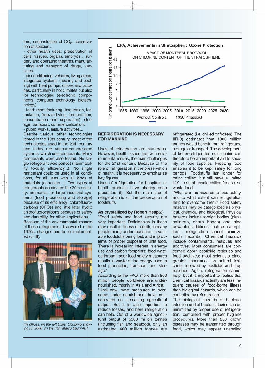
EPA, Achievements in Stratospheric Ozone Protection
IMPACT OF MONTREAL PROTOCOLON CHLORINE CONTENT OF THE STRATOSPHERE
IIR offices: on the left Didier Coulomb show-ing ISI 2006, on the right Marco Buoni-ATF.
even when containing excessive num-bers of disease-producing organisms.A study in the USA (1999) showed thenumber of illnesses and deaths fromfood borne pathogens. Annually, therewere an estimated 1777 deaths and13.65 million illnesses from knownpathogens, out of a total of 76 millionillnesses and 5000 deaths from allfood borne diseases.The actual causes of food poisoningare contamination, microbial survival,and microbial growth. It is clear thatimproper refrigeration is the largestfactor: over 90% of these illnesses areat least partly associated with temper-ature control.That issue will certainly be taken intoconsideration to a greater extent in thecoming years. The population isincreasing (more than 9 billion inhabi-tants in 2050, 1/3rd more than now),essentially in developing countrieswhere the cold chain is underdevel-oped. Moreover, the population livingin cities will double in these countries.In developed countries, the dominant-ly urban population will comprise ris-ing numbers of elderly persons whoare more prone to foodborne illnessesthan younger persons. Air conditioningwill also be more necessary for theseelderly persons.
THE ENVIRONMENTAL ISSUE (4)
Until the1970s, only toxicity and flam-mability of certain refrigerants wereenvironmental problems.
“The ozone layerIn 1974, Molina and Rowland noticeddepletion of the stratospheric ozonelayer protecting the Earth from harmfulultraviolet solar radiation for the firsttime. Soon, several chemicals were incrimi-nated, even though the debate con-cerning the ongoing chemical andphysical phenomena and who wasresponsible lasted a decade.Chlorinated substances such as chlo-rofluorocarbons (CFCs) and hydro-chlorofluorocarbons (HCFCs) used inaerosols, foams and as refrigerantswere among these substances. CFCs,R12 in particular, and HCFCs soonafter, had widely replaced previousrefrigerants, with the exception ofammonia.
The 1985 Vienna Convention marks arelative scientific and political consen-sus in favour of the progressivephase-out of ozone-depleting sub-stances and led to the signing of theMontreal Protocol in 1987. ThisProtocol was then progressivelysigned (over the next 15 years) by var-ious stakeholders and was rapidlyimplemented thanks to the immediateinvolvement of the main contributors:governments of developed and devel-oping countries, but also industrialstakeholders, manufacturers andusers of these substances. The pro-gressive phase-out time frame ofthese substances until 2040, demon-strates a willingness to apply long-term planning.The Protocol made it possible todevelop new refrigerants without anyimpact on the ozone layer (hydrofluo-rocarbons, HFCs) or to rediscover oldno longer used refrigerants, such ascarbon dioxide (CO2), that could bemade competitive thanks to a fewtechnical improvements.This Protocol was a widely acclaimedworldwide success, probably becauseit was unfortunately one of the onlytrue achievements of internationalcooperation. Current measurementsof the ozone layer show an overall sta-bility and probable recovery to the pre-vious level around 2060.
Global warmingMeanwhile, scientists gradually alert-
ed the public about another phenome-non: global warming. Rising globaltemperature measurements and theircorrelation with the increase in CO2 inthe atmosphere progressively ledobservers to notice that human activi-ty produced gases that significantlyincreased the natural greenhouseeffect around the Earth. This theoryraised controversy initially, but is nowvery broadly accepted by the scientificcommunity. It led to the signing, by theinternational community, of the RioConvention in 1992, then the KyotoProtocol in 1997. Several greenhouse gases were iden-tified. The main one in terms of itsglobal impact, due to the quantitiesreleased (as its global warming poten-tial is very low) is CO2. CO2 emissionsare essentially due to the burning offuel in transport and the heating ofbuildings, to industrial processesusing fossil fuels and to power pro-duction. Electricity is mainly producedfrom oil, coal or natural gas in mostcountries. Other greenhouse gasesexist, in particular refrigerants: variousCFCs, HCFCs, and HFCs have aglobal warming potential that is about100-10 000-fold that of CO2.Of course, they are released in verysmall quantities into the atmosphere,only in the case of defective leak tight-ness of systems or in the case of poorrecovery of scrapped obsolete equip-ment. However, they have an impacton the overall greenhouse effect that
10
AFEAS, ODP weighted Fluorocarbon Production (1980-2004)
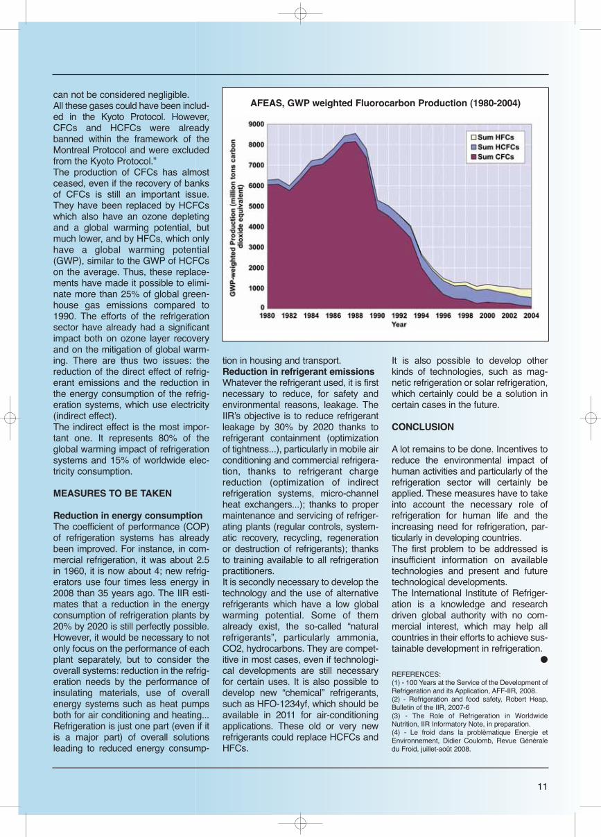
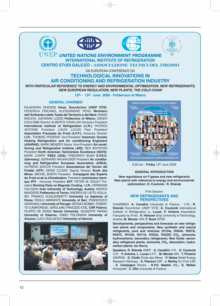
can not be considered negligible. All these gases could have been includ-ed in the Kyoto Protocol. However,CFCs and HCFCs were alreadybanned within the framework of theMontreal Protocol and were excludedfrom the Kyoto Protocol.”The production of CFCs has almostceased, even if the recovery of banksof CFCs is still an important issue.They have been replaced by HCFCswhich also have an ozone depletingand a global warming potential, butmuch lower, and by HFCs, which onlyhave a global warming potential(GWP), similar to the GWP of HCFCson the average. Thus, these replace-ments have made it possible to elimi-nate more than 25% of global green-house gas emissions compared to1990. The efforts of the refrigerationsector have already had a significantimpact both on ozone layer recoveryand on the mitigation of global warm-ing. There are thus two issues: thereduction of the direct effect of refrig-erant emissions and the reduction inthe energy consumption of the refrig-eration systems, which use electricity(indirect effect).The indirect effect is the most impor-tant one. It represents 80% of theglobal warming impact of refrigerationsystems and 15% of worldwide elec-tricity consumption.
MEASURES TO BE TAKEN
Reduction in energy consumptionThe coefficient of performance (COP)of refrigeration systems has alreadybeen improved. For instance, in com-mercial refrigeration, it was about 2.5in 1960, it is now about 4; new refrig-erators use four times less energy in2008 than 35 years ago. The IIR esti-mates that a reduction in the energyconsumption of refrigeration plants by20% by 2020 is still perfectly possible.However, it would be necessary to notonly focus on the performance of eachplant separately, but to consider theoverall systems: reduction in the refrig-eration needs by the performance ofinsulating materials, use of overallenergy systems such as heat pumpsboth for air conditioning and heating...Refrigeration is just one part (even if itis a major part) of overall solutionsleading to reduced energy consump-
tion in housing and transport.Reduction in refrigerant emissionsWhatever the refrigerant used, it is firstnecessary to reduce, for safety andenvironmental reasons, leakage. TheIIRʼs objective is to reduce refrigerantleakage by 30% by 2020 thanks torefrigerant containment (optimizationof tightness...), particularly in mobile airconditioning and commercial refrigera-tion, thanks to refrigerant chargereduction (optimization of indirectrefrigeration systems, micro-channelheat exchangers...); thanks to propermaintenance and servicing of refriger-ating plants (regular controls, system-atic recovery, recycling, regenerationor destruction of refrigerants); thanksto training available to all refrigerationpractitioners.It is secondly necessary to develop thetechnology and the use of alternativerefrigerants which have a low globalwarming potential. Some of themalready exist, the so-called “naturalrefrigerants”, particularly ammonia,CO2, hydrocarbons. They are compet-itive in most cases, even if technologi-cal developments are still necessaryfor certain uses. It is also possible todevelop new “chemical” refrigerants,such as HFO-1234yf, which should beavailable in 2011 for air-conditioningapplications. These old or very newrefrigerants could replace HCFCs andHFCs.
It is also possible to develop otherkinds of technologies, such as mag-netic refrigeration or solar refrigeration,which certainly could be a solution incertain cases in the future.
CONCLUSION
A lot remains to be done. Incentives toreduce the environmental impact ofhuman activities and particularly of therefrigeration sector will certainly beapplied. These measures have to takeinto account the necessary role ofrefrigeration for human life and theincreasing need for refrigeration, par-ticularly in developing countries.The first problem to be addressed isinsufficient information on availabletechnologies and present and futuretechnological developments.The International Institute of Refriger-ation is a knowledge and researchdriven global authority with no com-mercial interest, which may help allcountries in their efforts to achieve sus-tainable development in refrigeration.
●
REFERENCES:(1) - 100 Years at the Service of the Development ofRefrigeration and its Application, AFF-IIR, 2008.(2) - Refrigeration and food safety, Robert Heap,Bulletin of the IIR, 2007-6(3) - The Role of Refrigeration in WorldwideNutrition, IIR Informatory Note, in preparation.(4) - Le froid dans la problèmatique Energie etEnvironnement, Didier Coulomb, Revue Généraledu Froid, juillet-août 2008.
11
AFEAS, GWP weighted Fluorocarbon Production (1980-2004)
12
UNITED NATIONS ENVIRONMENT PROGRAMMEINTERNATIONAL INSTITUTE OF REFRIGERATION
CENTRO STUDI GALILEO - ASSOCIAZIONE TECNICI DEL FREDDOXIII EUROPEAN CONFERENCE ON
TECHNOLOGICAL INNOVATIONS INAIR CONDITIONING AND REFRIGERATION INDUSTRY
WITH PARTICULAR REFERENCE TO ENERGY AND ENVIRONMENTAL OPTIMIZATION, NEW REFRIGERANTS,NEW EUROPEAN REGULATION, NEW PLANTS, THE COLD CHAIN
12th - 13th June 2009 - Politecnico di Milano
GENERAL CHAIRMEN
RAJENDRA SHENDE Head, OzonAction UNEP DTIE;FEDERICA FRICANO, ALESSANDRO PERU MinisterodellʼAmbiente e della Tutela del Territorio e del Mare; ENNIOMACCHI, GIOVANNI LOZZA Politecnico of Milano; DIDIERCOULOMB Director ALBERTO CAVALLINI Honorary PresidentInternational Institute of Refrigeration (I.I.R.); PATRICKANTOINE President LOUIS LUCAS Past PresidentAssociation Française du Froid (A.F.F.); Honorary DirectorI.I.R.; THOMAS PHOENIX Vice-President American SocietyHeating Refrigeration and Air conditioning Engineers(ASHRAE); MARK MENZER Senior Vice-President Air-condi-tioning and Refrigeration Institute (ARI); REX BOYNTONPresident North American Technicians Excellence (NATE):MARK LOWRY RSES (USA); FRIEDRICH BUSH E.P.E.E.(Germany); GERHARD NAUHAUSER President Air conditio-ning and Refrigeration European Association (AREA);ALFREDO SACCHI President Associazione dei Tecnici delFreddo (ATF); DENIS CLODIC Deputy Director Ecole desMines; MICHEL BARTH President Compagnie des Expertsdu Froid et de la Climatisation; President commission tecni-que IFFI - Honorary President AFF; PETER W. EGOLF Pre-sident Working Party on Magnetic Cooling - I.I.R.; HERMANNHALOZAN Graz University of Technology, Austria; MARCOMASOERO Politecnico of Torino; ANDREA DE LIETO VOLLA-RO, FRANCO GUGLIERMETTI University La Sapienza ofRoma; PAOLO AMIRANTE University of Bari; FRANCESCOASDRUBALI University of Perugia; SERGIO BOBBO, ROBER-TO CAMPORESE, GIROLAMO PANOZZO I.T.C. CNR Padova;FILIPPO DE ROSSI Sannio University; GIUSEPPE PANNOUniversity of Palermo; FABIO POLONARA University ofAncona; LUCA TAGLIAFICO University of Genova
9,00 am - Friday 12th June 2009
GENERAL INTRODUCTION
New regulations on F-gases and new refrigerantsNew plants with reference to energy and environmental
optimization: D. Coulomb - R. Shende
First Session
NEW REFRIGERANTS ANDPERSPECTIVES
CHAIRMEN: A. Cavallini Università di Padova - I.I.R.; R.Shende OzonAction UNEP DTIE; D. Coulomb InternationalInstitute of Refrigeration; L. Lucas, P. Antoine AssociationFrançaise du Froid; H. Halozan Graz University of Technology,Austria; M. Menzer ARI; F. Bush EPEEDevelopments, perspectives and forecasts on new refrige-rant plants and components. New synthetic and naturalrefrigerants, pure and mixtures (R134a, R404A, R507A,R407C, R410A, R417A, R422A, R422D) CO2, ammonia,hydrocarbons; secondary refrigerants; New fluids: secon-dary refrigerant plants; ammonia, CO2, absorption, hydro-carbon plants, Ice Slurry.Speakers: R. Shende UNEP - A. Cavallini I.I.R. - D. CoulombI.I.R. - P. Antoine, L. Lucas A.F.F. - M. Menzer ARI - T. PhoenixASHRAE - D. Clodic Ecole des Mines - P. Neksa Sintef EnergyResearch (Norway) - A. Pearson IOR - J. Morley Du Pont (UK)- E. Campagna Rivoira - H.V.D. Maaten (NL), G. MatteoHoneywell - C. Zilio Università di Padova
13
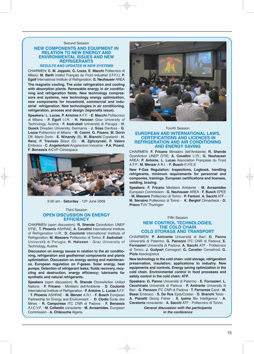
Second Session
NEW COMPONENTS AND EQUIPMENT INRELATION TO NEW ENERGY AND
ENVIRONMENTAL ISSUES AND NEWREFRIGERANTS
RESULTS AND UPDATES IN NEW SYSTEMS CHAIRMEN: C. M. Joppolo, G. Lozza, E. Macchi Politecnico diMilano; M. Barth Institut Français du Froid Industriel (I.F.F.I.); P.Egolf International Institute of Refrigeration; G. Neuhauser AREAThe magnetic cooling. The solar refrigeration and coolingwith absorption plants. Renewable energy in air conditio-ning and refrigeration fields. New technology compres-sors and systems, new technology energy optimization,new components for household, commercial and indu-strial refrigeration. New technologies in air conditioning,refrigeration, process and design (legionella issue). Speakers: L. Lucas, P. Antoine A.F.F. - E. Macchi Politecnicodi Milano - P. Egolf I.I.R. - H. Halozan Graz University ofTechnology, Austria - F. Asdrubali Università di Perugia - H.Quack Dresden University, Germania - J. Süss Danfoss - G.Lozza Politecnico di Milano - M. Casini, G. Pisano, M. DorinOff. Mario Dorin - E. Winandy (B), W. Bianchi Copeland - H.Renz, P. Trevisan Bitzer (D) - M. Zgliczynski, P. ValeroEmbraco - C. Angelantoni Angelantoni Industrie - P.A. Picard,F. Benassis AICVF-Climespace
9.00 am - Saturday - 13th June 2009
Third Session
OPEN DISCUSSION ON ENERGYEFFICIENCY
CHAIRMEN (open discussion): R. Shende OzonAction UNEPDTIE; T. Phoenix ASHRAE; A. Cavallini International Instituteof Refrigeration I.I.R.; D. Coulomb International Institute ofRefrigeration; M. Masoero Politecnico di Torino; F. Asdrubali -Università di Perugia; H. Halozan - Graz University ofTechnology, AustriaDiscussion on energy issues in relation to the air conditio-ning, refrigeration and geothermal components and plantsoptimization. Discussion on energy saving and maintenan-ce. European regulation on F-gases. Solar energy, heatpumps. Detection of refrigerant leaks; fluids recovery, recy-cling and destruction, energy efficiency; lubricants forsynthetic and natural refrigerants.Speakers (open discussion): R. Shende OzoneAction UnitedNations - F. Fricano - Ministero dellʼAmbiente - D. CoulombInternational Institute of Refrigeration - P. Antoine, L. Lucas A.F.F.- T. Phoenix ASHRAE - M. Menzer A.R.I. - F. Busch EuropeanPartnership for Energy and Environment - D. Clodic Ecole desMines - R. Camporese ITC CNR di Padova - F. BenassisA.I.C.V.F. - M. Collantin consulente - M. Avraamides, EuropeanCommission - A. Chikouche Algeria
Fourth Session
EUROPEAN AND INTERNATIONAL LAWS,CERTIFICATIONS AND LICENCES IN
REFRIGERATION AND AIR CONDITIONINGAND ENERGY SAVING
CHAIRMEN: F. Fricano Ministero dellʼAmbiente; R. ShendeOzonAction UNEP DTIE; A. Cavallini I.I.R.; G. NauhauserAREA; P. Antoine, L. Lucas Association Française du FroidA.F.F.; M. Menzer A.R.I. - F. Busch E.P.E.ENew F-Gas Regulation: Inspections, Logbook, handlingrefrigerants, minimum requirements for personnel andcompanies, trainings. European certifications and licenses,welding, brazing. Speakers: F. Fricano Ministero Ambiente - M. AvraamidesEuropean Commission - G. Nauhauser AREA - F. Busch EPEE- M. Masoero Politecnico di Torino - P. Fantoni, A. Sacchi ATF -M. Serraino Politecnico di Torino - K. Berglof Climacheck - D.Prisco TUV Thuringen
Fifth Session
NEW CONTROL TECHNOLOGIES, THE COLD CHAIN
COLD STORAGE AND TRANSPORTCHAIRMEN: P. Amirante Università di Bari; G. PannoUniversità di Palermo; G. Panozzo ITC CNR di Padova; E.Fornasieri Università di Padova; A. Sacchi ATF - Politecnicodi Torino; J. Guilpart Cemagref; G. Cavalier Cemafroid; G.Piola AssologisticaNew technology in the cold chain: cold storage, refrigerationpreservation, insulation; applications to industry. Newequipments and controls. Energy saving optimization in thecold chain. Environmental control in food processes andsafety control in the cold chain: ATP.Speakers: G. Panno Università di Palermo - E. Fornasieri, L.Cecchinato Università di Padova - P. Amirante Università diBari - G. Panozzo ITC CNR di Padova - T. Ferrarese Carel - M.Bassi Embraco - S. Da Ros Epta/Costan - D. Branchi Testo -A. Pianetti Georg Fisher - S. Iyama Bio Intelligence - A.Cavatorta consulente - A. Sacchi ATF - Politecnico di Torino
General discussion with the participantsin the conference
14
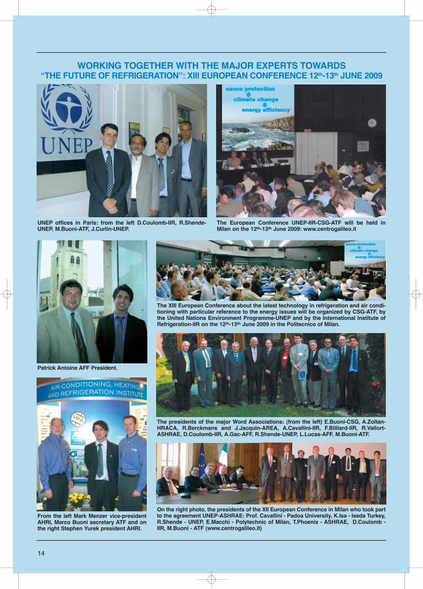
WORKING TOGETHER WITH THE MAJOR EXPERTS TOWARDS “THE FUTURE OF REFRIGERATION”: XIII EUROPEAN CONFERENCE 12th-13th JUNE 2009
UNEP offices in Paris: from the left D.Coulomb-IIR, R.Shende-UNEP, M.Buoni-ATF, J.Curlin-UNEP.
The European Conference UNEP-IIR-CSG-ATF will be held inMilan on the 12th-13th June 2009: www.centrogalileo.it
Patrick Antoine AFF President.
From the left Mark Menzer vice-presidentAHRI, Marco Buoni secretary ATF and onthe right Stephen Yurek president AHRI.
The XIII European Conference about the latest technology in refrigeration and air condi-tioning with particular reference to the energy issues will be organized by CSG-ATF, bythe United Nations Environment Programme-UNEP and by the International Institute ofRefrigeration-IIR on the 12th-13th June 2009 in the Politecnico of Milan.
The presidents of the major Word Associations: (from the left) E.Buoni-CSG, A.Zoltan-HRACA, R.Berckmans and J.Jacquin-AREA, A.Cavallini-IIR, F.Billiard-IIR, R.Vallort-ASHRAE, D.Coulomb-IIR, A.Gac-AFF, R.Shende-UNEP, L.Lucas-AFF, M.Buoni-ATF.
On the right photo, the presidents of the XII European Conference in Milan who took partto the agreement UNEP-ASHRAE: Prof. Cavallini - Padoa University, K.Isa - Iseda Turkey,R.Shende - UNEP, E.Macchi - Polytechnic of Milan, T.Phoenix - ASHRAE, D.Coulomb -IIR, M.Buoni - ATF (www.centrogalileo.it)
This article describes the trends ofcommercial refrigeration, with particu-lar reference to experiences being car-ried out by industries and researchinstitutions in the NW of Italy, in order toenhance the energy and environmentalperformance of equipment and compo-nents. In particular, a case study is dis-cussed concerning the opportunitiesfor aeronautical applications.
INTRODUCTION
Commercial refrigeration is an impor-tant segment in the food chain: itincludes equipment such as vendingmachines that are common in mostbuildings open to the public, displaycabinets for refrigerated or frozen foodthat are present in any store or super-market, as well as refrigerated trans-portation.In Italy, the main productive district forcommercial refrigeration is located inthe area around the city of CasaleMonferrato, in the North-Westernregion of Piemonte, where about 20different industries produce a fullrange of components and completeequipment for all typical applications.In order to face the commercial andindustrial challenges posed both byglobalisation and by environmentalconcerns, the refrigeration industry isdeveloping a significant effort, involv-ing the whole chain of product innova-tion, from design down to manufactur-ing and marketing, including the appli-cation to new sectors. This paper outlines some of the main
trends of design innovation, which aremostly significant in terms of energyefficiency and environmental perform-ance; it also presents a new applica-tion in the aeronautics sector.
TECHNOLOGICAL AND DESIGNINNOVATION
The technological core of any refriger-ation equipment is clearly placed inthe thermodynamic process leading tothe production of a useful coolingeffect. At present, no viable alterna-tives to the classical vapour-compres-sion inverse cycle seem at hand; per-formance enhancement of such cyclesinvolves both the selection of the refrig-erant fluid, as well as the optimisationof all system components: compres-sor, heat exchangers, expansiondevice, and controls.The substitution of CFCs with the moreozone-friendly HCFCs and HFCs isnow a well established practice inEurope, following the implementationin the year 2000 of the EU 2037 stan-dard. The adoption of such fluids, how-ever, has not completely solved theenvironmental problems associatedwith refrigeration, since HFCs still con-tribute to global warming: in responseto such concerns, the recently intro-duced F-gas Regulations have set theobligations and practices to avoid acci-dental release of refrigerant fluids dur-ing system manufacturing, operation,maintenance, and phase-out. As an alternative to synthetic fluidssuch as HFCs, a great deal of attention
15
Trends in CommercialRefrigeration
PIETRO ASINARI - MARCO MASOERO - MICHELE CALÌ
Department of Energetics DENER - Politecnico di Torino - Italy
The Department of Energetics(DENER) of Politecnico di Torino(POLITO) is active since 1982 inresearch and consulting in mostareas related to energy processes:energy planning andenvironmental impact assessment,renewable energy sources,hydrogen technologies and fuelcells, nuclear physics andengineering, automotive andaerospace propulsion, end-useefficiency in the residential,tertiary and industrial sectors.Teaching activities at the Bachelor,Master and Doctorate levels areprovided by a staff of over 60faculty members, active in theEngineering and Architectureschools of POLITO.In the refrigeration sector, DENERis currently conducting researchon innovative systems forstationary, automotive andaeronautics applications, withparticular attention to theemployment of natural refrigerantssuch as CO2. Cryogenicsapplications are also investigatedas part of international researchprograms on nuclear fusion (ITERproject). Another important line ofactivity addresses the efficiency ofrefrigeration equipment in airconditioning (Project Harmonac,funded by the EC within theframework of the EIE program) andthe performance of reversible heatpump systems (Annex 48 of theIEA-ECBS program).
Pietro Asinari - Marco Masoero
has been devoted to natural refriger-ants such as ammonia, hydrocarbons(HCs), and carbon dioxide (CO2). Theiruse is already quite common for select-ed applications, e.g. HCs in domesticrefrigeration and CO2 in air conditioningsystems for automotive or aeronauticsapplications. One barrier to the diffu-sion of natural refrigerants is the lack ofinternational standards regulating theiruse; typically, a limit is placed on themaximum amount of refrigerant thatthe thermodynamic cycle may use,which leads to system fractioning athigh cooling demand.The transition to natural refrigerantsobviously implies a substantialredesign of the main system compo-nents: in particular, CO2 poses themost serious technological anddesign challenges. The heat transfercharacteristics of CO2 are better thenfor any other natural fluid, but stillworse then for synthetic fluids such asHFCs. Furthermore, the transcriticalnature of the CO2 refrigeration cycleimplies a thorough redesign of boththe compressor and condenser, due tothe extremely high operating pressures(on the order of 100 bar) and to the factthat the heat rejection process takesplaces in liquid phase, with tempera-ture excursions that may exceed100°C, rather then in a constant-tem-perature phase-change process. An essential role in CO2 cycles isplayed by controls. An optimal maxi-mum operating pressure in fact existsfor any evaporating condition deter-mined by the specific type of applica-tion. This implies the use of more
sophisticated pressure regulatingdevices, capable of tracking the opti-mal pressure differential for varyingoperating conditions.A central role for a successful opera-tion is played by the compressor. Akey factor is the fluid tightness, whichbecomes critical at such high pres-sures: for commercial applicationshermetic compressors are preferred tosemi-hermetic ones, which are cus-tomarily used in the automotive andaeronautics sectors.Even in the case of conventional flu-ids, innovation in controls may sub-stantially help increasing the energyperformance: it is the case of variable-speed compressors, based on invert-ers that are already common in largeindustrial refrigeration plants and in airconditioning, and are now appearingalso in new commercial units.Further down the line are more radicalinnovations - such as Peltier-effect orejector-cycle refrigeration - that how-ever still require a substantial R&Deffort in order to assess their industrialfeasibility.The energy performance enhance-ment of a commercial refrigerationsystem is also determined by thereduction of its cooling load: thisimplies a better thermal insulation ofthe glazed and opaque envelope, thecontrol of unwanted outdoor air infiltra-tion, and a better efficiency of the light-ing systems placed inside the refriger-ated compartment.Transfer of technologies that arealready well established in the buildingsector is one possible way for achiev-
ing this goal: using high performanceglazing with U-values as low as 1.1W/m2K in place of conventional dou-ble glazing (U = 3 W/m2K), controllingair infiltration with air barriers in opendisplay cabinets, and substituting con-ventional fluorescent lamps with moreefficient LED systems or with externallight sources equipped with optic fibresto channel the light inside the refriger-ated space, are a few examples ofsuch technologies that may be suc-cessfully applied to commercial refrig-eration.The thermal insulation of the opaquewalls is now typically made withexpanded polyurethane foam. Thissolution has several advantages -namely, ease of production, low costs,and high thermal performance - butone serious disadvantage: beingpolyurethane a thermoset resin (ratherthen a thermoplastic one), it may notbe recycled. This problem leads us into another fun-damental aspect of the environmentalperformance of commercial refrigera-tion equipment: what to do when theyare phased out (the problem is particu-larly relevant, due to the much shorteroperating life of a commercial refrigera-tor - typically 2-3 years - compared to adomestic one). Today, phased-out unitsare disassembled: the refrigerant fluidis recovered, the compressor is extract-ed and molten (with the lubricant fluidstill inside), valuable heat exchangermaterials (aluminium and copper) arerecovered together with glass and themetal sheets that make up the externalenvelope, while polyurethane is sub-jected to grinding and successive dis-posal as a waste.In order to minimise the waste dispos-al problem and the environmental per-formance in more general terms, LifeCycle Analysis techniques may beapplied, leading to a more effective“Cradle-to-Grave” design process, inwhich the equipment is conceived bytaking into account not only its per-formance during operation, but alsothe energy costs of construction andthe possibility of complete recovery ofthe materials after phasing out.A sector that shows very promisingpotential for technological innovationis refrigerated transportation, whichincludes short-range distribution offresh products (e.g. fruits and vegeta-
16
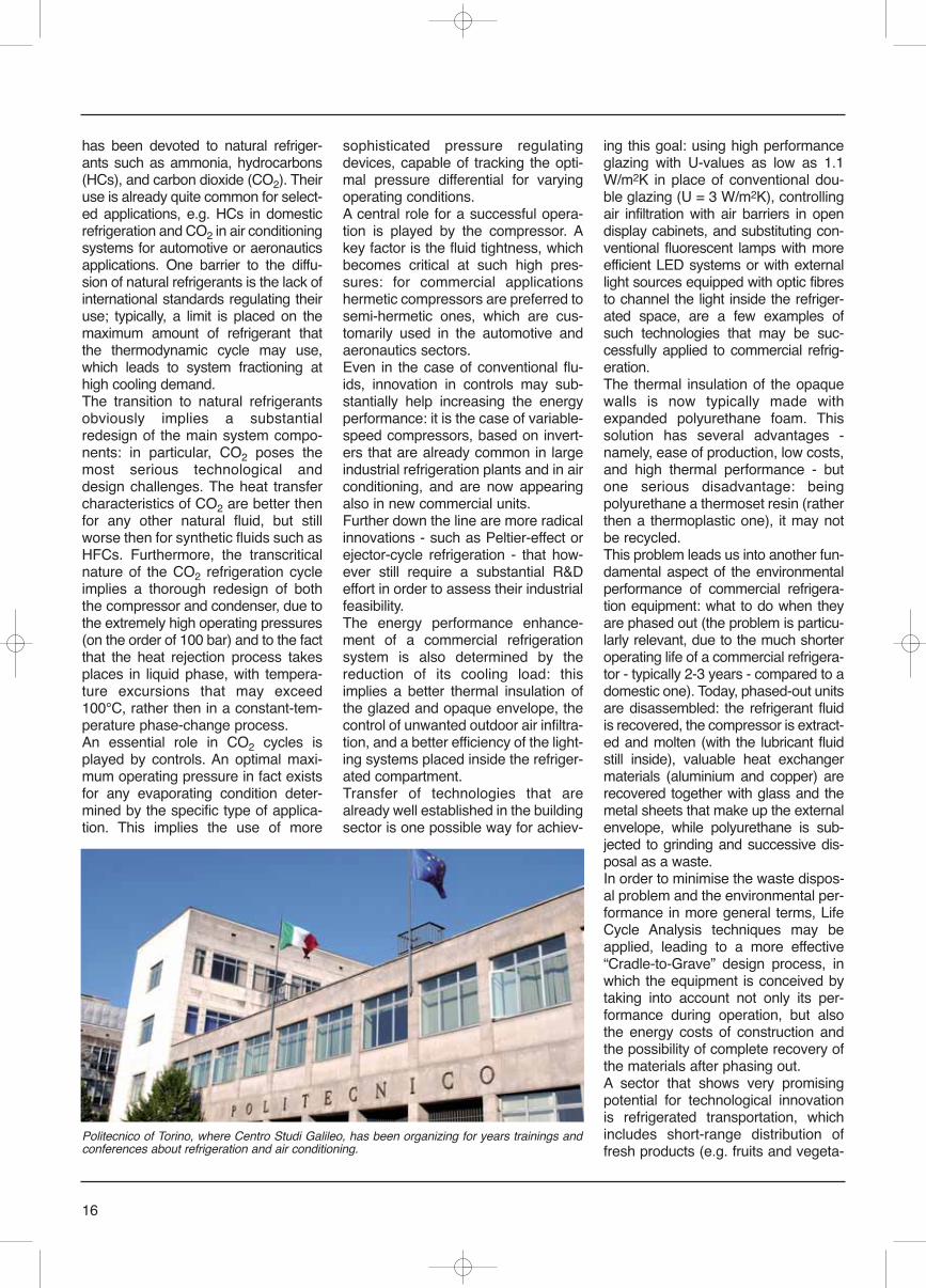
Politecnico of Torino, where Centro Studi Galileo, has been organizing for years trainings andconferences about refrigeration and air conditioning.
bles, dairy products, etc.) as well aslong-range transportation of refrigerat-ed or frozen food that must be con-served for weeks. The main innovativetrends concern the design of the evap-orator (e.g. the use of finned-tubeforced-convection compact heatexchangers) and the adoption of pas-
sive refrigeration systems (PRS). PRSmakes use of phase-changing materi-als (PCM), typically eutectic salts, toaccumulate a sufficient amount ofrefrigeration energy that is subsequent-ly released over the time required tomaintain the desired temperature levelin the refrigerated compartment.This concept may be used in principlefor any type of application, but is partic-ularly interesting for long-range (up to30 days) storage, as an alternative tothe conventional reefer containers, inwhich the complete refrigerating unit(compressor included) is mounted onboard: with PRS containers, the cool-ing system is initially “charged” with adedicated unit, the refrigerated contain-er only is shipped, while the refrigerat-ing station remains ashore. A furtheradvantage of this concept is that thePCM remains at a temperature veryclose to that of air: this avoids anexcessive dehumidification of air,reducing dishydratation and weightloss of the foodstuff, as well as the
need of defrosting of the heat exchang-er.COMMERCIAL REFRIGERATIONGOES ABOARD
The previous outline clearly shows theopportunities for innovation in the com-mercial refrigeration sector. The coop-eration with public scientific institutionsappears to be a promising formula fordeveloping industrial research partner-ships that may be mutually beneficialfor the academic as well as the indus-trial world. In the following, a case studyis discussed concerning the opportuni-ties for aeronautical applications.In the aircraft industry, the termEnvironmental Control System (ECS)is used to identify the devices realizingsuitable environmental conditions forpassengers and crew inside the cabin[1]. In the commercial transport air-crafts, air-cycle air conditioning for theECS represents the largely predomi-nant strategy. This strategy is usuallya matter of convenience due to the
17
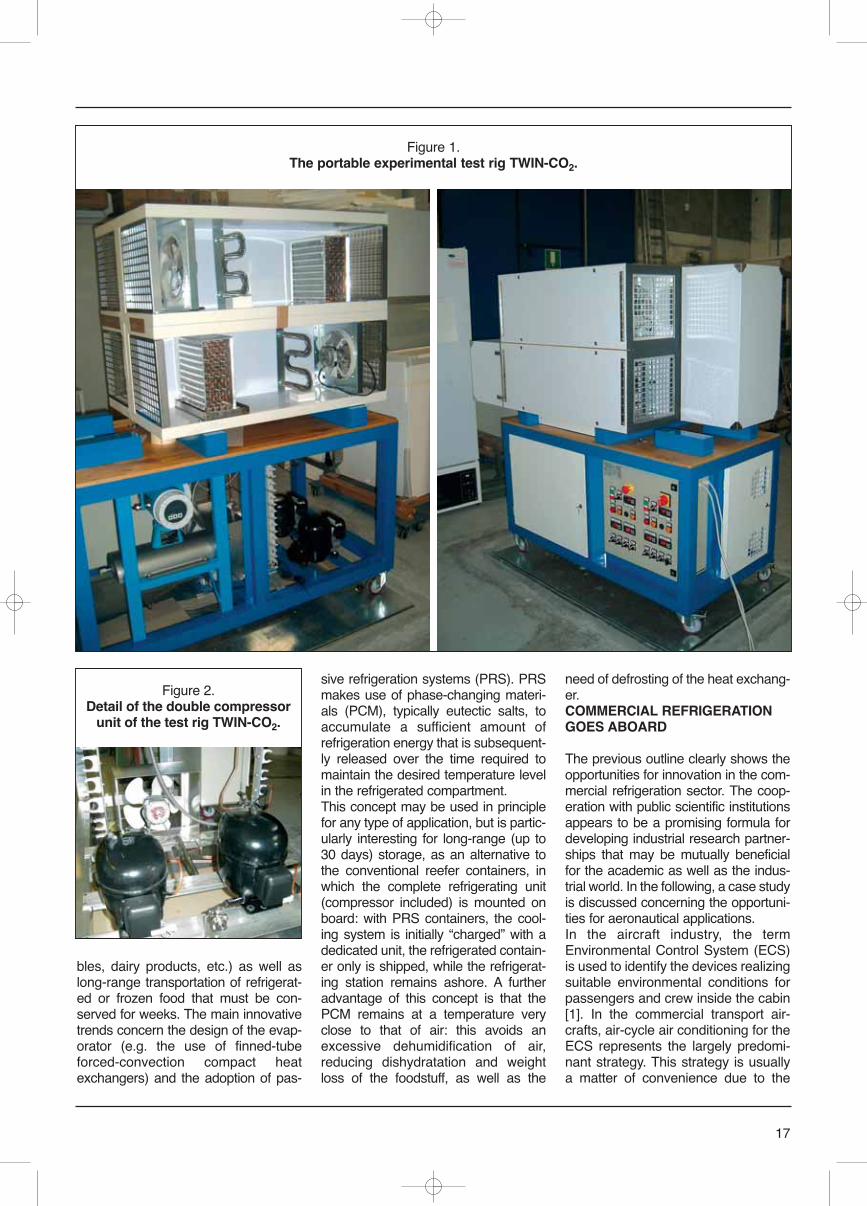
Figure 1. The portable experimental test rig TWIN-CO2.
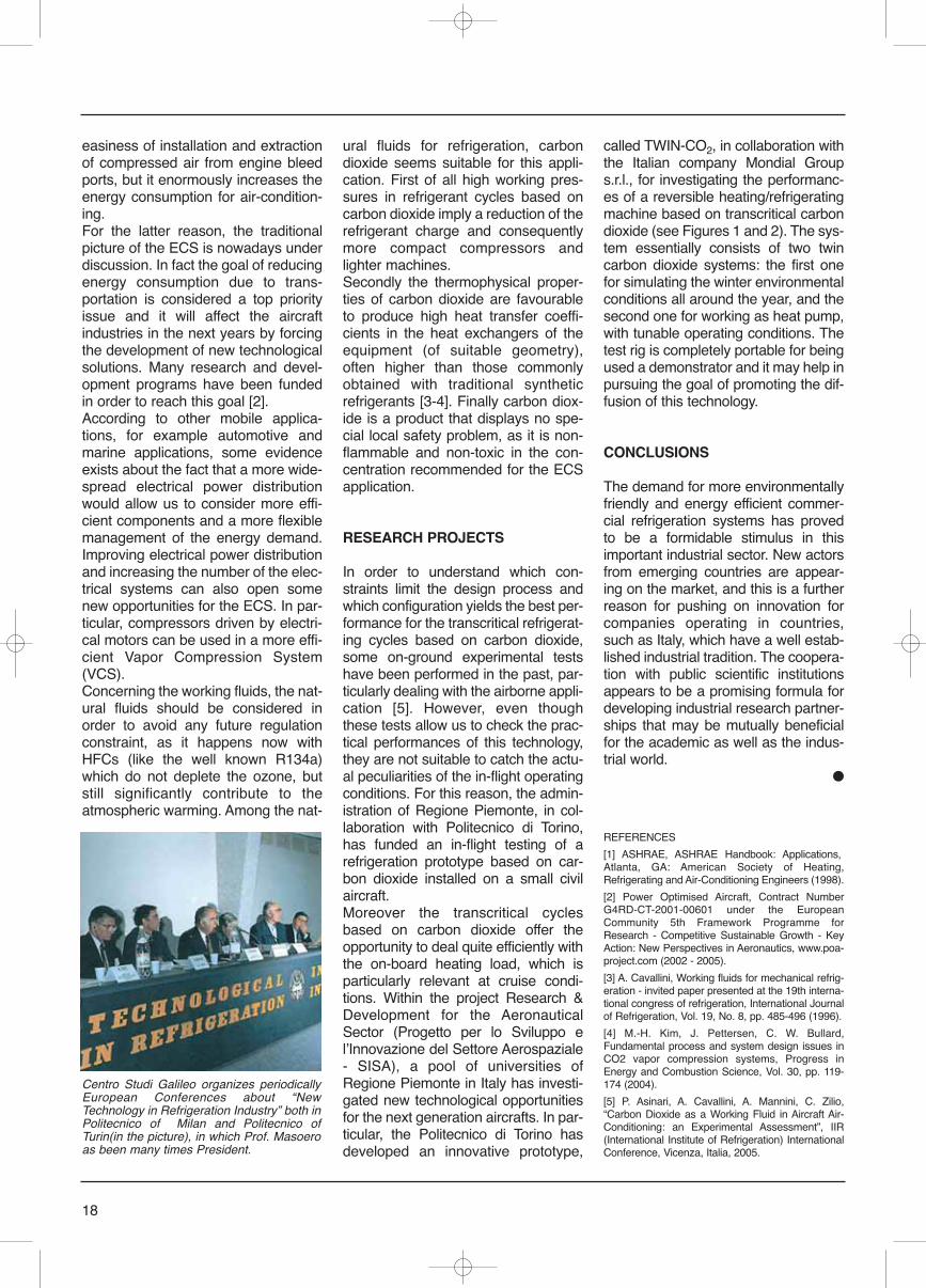
Figure 2. Detail of the double compressor
unit of the test rig TWIN-CO2.
easiness of installation and extractionof compressed air from engine bleedports, but it enormously increases theenergy consumption for air-condition-ing.For the latter reason, the traditionalpicture of the ECS is nowadays underdiscussion. In fact the goal of reducingenergy consumption due to trans-portation is considered a top priorityissue and it will affect the aircraftindustries in the next years by forcingthe development of new technologicalsolutions. Many research and devel-opment programs have been fundedin order to reach this goal [2].According to other mobile applica-tions, for example automotive andmarine applications, some evidenceexists about the fact that a more wide-spread electrical power distributionwould allow us to consider more effi-cient components and a more flexiblemanagement of the energy demand.Improving electrical power distributionand increasing the number of the elec-trical systems can also open somenew opportunities for the ECS. In par-ticular, compressors driven by electri-cal motors can be used in a more effi-cient Vapor Compression System(VCS). Concerning the working fluids, the nat-ural fluids should be considered inorder to avoid any future regulationconstraint, as it happens now withHFCs (like the well known R134a)which do not deplete the ozone, butstill significantly contribute to theatmospheric warming. Among the nat-
ural fluids for refrigeration, carbondioxide seems suitable for this appli-cation. First of all high working pres-sures in refrigerant cycles based oncarbon dioxide imply a reduction of therefrigerant charge and consequentlymore compact compressors andlighter machines.Secondly the thermophysical proper-ties of carbon dioxide are favourableto produce high heat transfer coeffi-cients in the heat exchangers of theequipment (of suitable geometry),often higher than those commonlyobtained with traditional syntheticrefrigerants [3-4]. Finally carbon diox-ide is a product that displays no spe-cial local safety problem, as it is non-flammable and non-toxic in the con-centration recommended for the ECSapplication.
RESEARCH PROJECTS
In order to understand which con-straints limit the design process andwhich configuration yields the best per-formance for the transcritical refrigerat-ing cycles based on carbon dioxide,some on-ground experimental testshave been performed in the past, par-ticularly dealing with the airborne appli-cation [5]. However, even thoughthese tests allow us to check the prac-tical performances of this technology,they are not suitable to catch the actu-al peculiarities of the in-flight operatingconditions. For this reason, the admin-istration of Regione Piemonte, in col-laboration with Politecnico di Torino,has funded an in-flight testing of arefrigeration prototype based on car-bon dioxide installed on a small civilaircraft.Moreover the transcritical cyclesbased on carbon dioxide offer theopportunity to deal quite efficiently withthe on-board heating load, which isparticularly relevant at cruise condi-tions. Within the project Research &Development for the AeronauticalSector (Progetto per lo Sviluppo elʼInnovazione del Settore Aerospaziale- SISA), a pool of universities ofRegione Piemonte in Italy has investi-gated new technological opportunitiesfor the next generation aircrafts. In par-ticular, the Politecnico di Torino hasdeveloped an innovative prototype,
called TWIN-CO2, in collaboration withthe Italian company Mondial Groups.r.l., for investigating the performanc-es of a reversible heating/refrigeratingmachine based on transcritical carbondioxide (see Figures 1 and 2). The sys-tem essentially consists of two twincarbon dioxide systems: the first onefor simulating the winter environmentalconditions all around the year, and thesecond one for working as heat pump,with tunable operating conditions. Thetest rig is completely portable for beingused a demonstrator and it may help inpursuing the goal of promoting the dif-fusion of this technology.
CONCLUSIONS
The demand for more environmentallyfriendly and energy efficient commer-cial refrigeration systems has provedto be a formidable stimulus in thisimportant industrial sector. New actorsfrom emerging countries are appear-ing on the market, and this is a furtherreason for pushing on innovation forcompanies operating in countries,such as Italy, which have a well estab-lished industrial tradition. The coopera-tion with public scientific institutionsappears to be a promising formula fordeveloping industrial research partner-ships that may be mutually beneficialfor the academic as well as the indus-trial world.
●
REFERENCES
[1] ASHRAE, ASHRAE Handbook: Applications,Atlanta, GA: American Society of Heating,Refrigerating and Air-Conditioning Engineers (1998).
[2] Power Optimised Aircraft, Contract NumberG4RD-CT-2001-00601 under the EuropeanCommunity 5th Framework Programme forResearch - Competitive Sustainable Growth - KeyAction: New Perspectives in Aeronautics, www.poa-project.com (2002 - 2005).
[3] A. Cavallini, Working fluids for mechanical refrig-eration - invited paper presented at the 19th interna-tional congress of refrigeration, International Journalof Refrigeration, Vol. 19, No. 8, pp. 485-496 (1996).
[4] M.-H. Kim, J. Pettersen, C. W. Bullard,Fundamental process and system design issues inCO2 vapor compression systems, Progress inEnergy and Combustion Science, Vol. 30, pp. 119-174 (2004).
[5] P. Asinari, A. Cavallini, A. Mannini, C. Zilio,“Carbon Dioxide as a Working Fluid in Aircraft Air-Conditioning: an Experimental Assessment”, IIR(International Institute of Refrigeration) InternationalConference, Vicenza, Italia, 2005.
18
Centro Studi Galileo organizes periodicallyEuropean Conferences about “NewTechnology in Refrigeration Industry” both inPolitecnico of Milan and Politecnico ofTurin(in the picture), in which Prof. Masoeroas been many times President.
Heat pumps and reversible units areconsidered as a viable solution for thereduction of primary energy consump-tion in heating and refrigerating appli-cations. In this paper water-heating heatpumps operating with transcritical car-bon dioxide vapour compression cycleare considered. For this particularapplication the market looks promis-ing, especially in Japan where theGovernment, thanks to a favourablelegislation, forecasts that the installedunits in 2010 will be around 5 million.With regard to hydrocarbons, the use of
propane as the refrigerant in heatpumps is reviewed. The main problemrelated to the adoption of hydrocarbonsis their flammability, which has prevent-ed their use in large scale. Additionalsafety restrictions are then requiredand, since the possible hazardsdepend on the total amount of refriger-ant trapped in the system, the chargeminimization is a major design con-straint. Some technological results arereported in the present paper, with par-ticular focus to the charge reduction.Key Words: heat pumps, carbondioxide, hydrocarbons, heating/co-oling systems
INTRODUCTION
In the last years a strong researchactivity has been carried out inresearch institutions and in forward-looking refrigeration companies for thedevelopment of high efficient heatpumps operating with fluids not harm-ful to the environment. Having theTEWI concept as the benchmark, theoptimization target is to reduce asmuch as possible both the “directimpact”, that is the effect of the refrig-erant when released into the atmos-phere, and the “indirect impact”, that islinked to the equipment’s efficiency.The development of efficient heatpumps working with “natural” fluidsseems to be the ultimate solution.Based on this technological roadmap,two options are here considered, withreference to different fluid categories:carbon dioxide and hydrocarbons.
CARBON DIOXIDETRANSCRITICAL HEAT PUMPS
Since Gustav Lorentzen milestonework (1993), that can be consideredthe “manifesto” of the “modern” use ofCO2 as a refrigerant, several applica-tions have been investigated to provethe workability of the new “transcritical”technology. Among the most promisingapplications it is worth mentioning thefollowing: heat pumps and waterheaters, mobile air conditioning, com-mercial systems, industrial refrigeration(both transcritical and cascade), sec-ondary coolant applications.Thanks to much academic researchwork, supported by a group of inter-ested industrial partners, the techno-logical feasibility of the proposed“revival” of carbon dioxide is nowdemonstrated and now the efforts aredevoted to enable the technology itselfto compete in the market. From thisstandpoint, extremely promisingappears the market for CO2 heatpump water heaters, especially inJapan, where the Government, thanksto a favourable legislation, forecaststhat the installed units in 2010 will bearound 5.2 million. The U.S. company Carrier, within theUnited Technologies Research Centre(Huff and Sienel, 2006), has devel-oped a series of commercially sizedCO2 heat pump water heaters nowinstalled and operating into a diverserange of geographic and applicationsites across the USA. The field testshave indicated quite promising resultsin terms of system performance, relia-
19
Heat pumps using naturalworking fluids: an environmental friendly solution
ALBERTO CAVALLINI, DAVIDE DEL COL, CLAUDIO ZILIO
Dipartimento di Fisica Tecnica - University of PadovaAlberto Cavallini
The University of Padova wasfounded in 1222 and comprisesmany Faculties; at present about65,000 students in severalsubjects with more than 2000teachers are attending theUniversity of Padova. Within this, the Dipartimento diFisica Tecnica of the EngineeringFaculty gets together 20 teachersand research workers. The research activities of theDepartment are devoted tothermodynamics, heat transfer,refrigeration technology, heatpumps, air conditioning,renewable energy, thermodynamicproperties of refrigerants,applied acoustics.
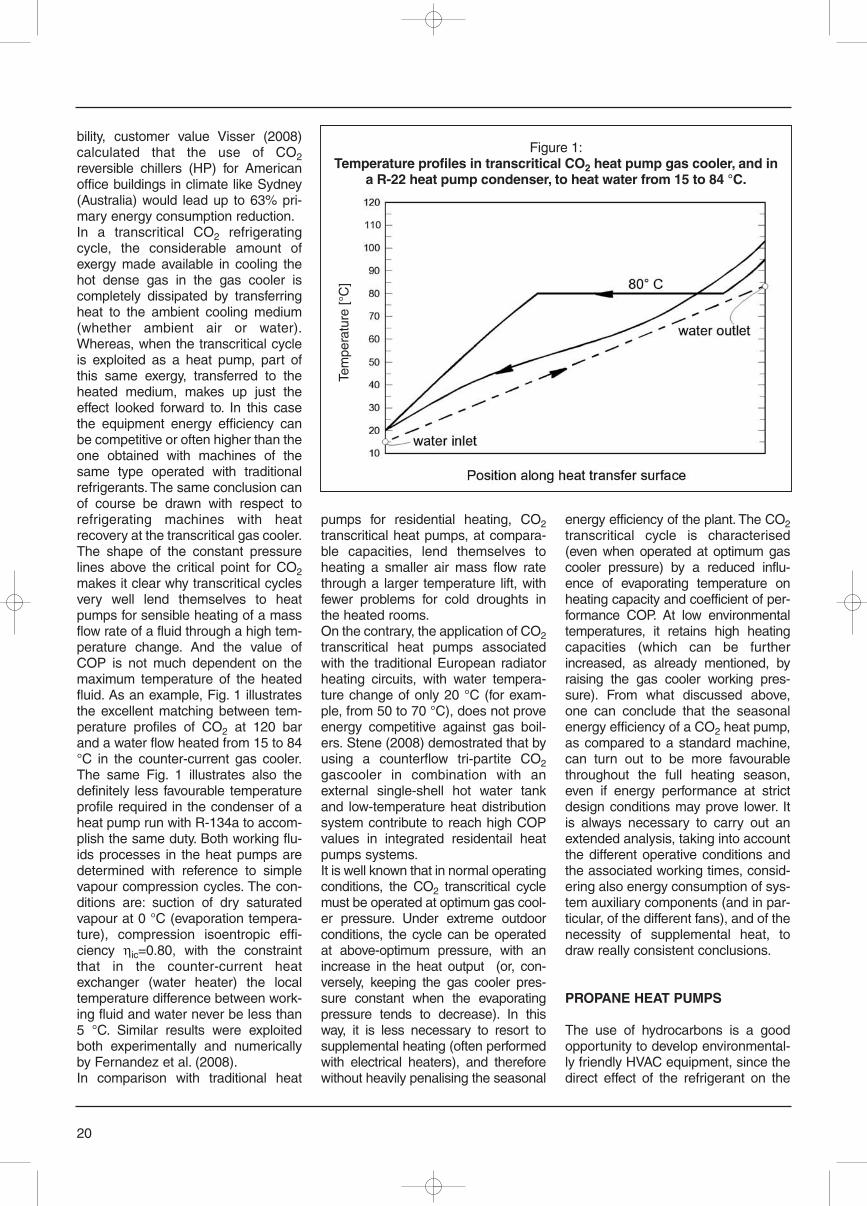
bility, customer value Visser (2008)calculated that the use of CO2reversible chillers (HP) for Americanoffice buildings in climate like Sydney(Australia) would lead up to 63% pri-mary energy consumption reduction.In a transcritical CO2 refrigeratingcycle, the considerable amount ofexergy made available in cooling thehot dense gas in the gas cooler iscompletely dissipated by transferringheat to the ambient cooling medium(whether ambient air or water).Whereas, when the transcritical cycleis exploited as a heat pump, part ofthis same exergy, transferred to theheated medium, makes up just theeffect looked forward to. In this casethe equipment energy efficiency canbe competitive or often higher than theone obtained with machines of thesame type operated with traditionalrefrigerants. The same conclusion canof course be drawn with respect torefrigerating machines with heatrecovery at the transcritical gas cooler.The shape of the constant pressurelines above the critical point for CO2makes it clear why transcritical cyclesvery well lend themselves to heatpumps for sensible heating of a massflow rate of a fluid through a high tem-perature change. And the value ofCOP is not much dependent on themaximum temperature of the heatedfluid. As an example, Fig. 1 illustratesthe excellent matching between tem-perature profiles of CO2 at 120 barand a water flow heated from 15 to 84°C in the counter-current gas cooler.The same Fig. 1 illustrates also thedefinitely less favourable temperatureprofile required in the condenser of aheat pump run with R-134a to accom-plish the same duty. Both working flu-ids processes in the heat pumps aredetermined with reference to simplevapour compression cycles. The con-ditions are: suction of dry saturatedvapour at 0 °C (evaporation tempera-ture), compression isoentropic effi-ciency ηic=0.80, with the constraintthat in the counter-current heatexchanger (water heater) the localtemperature difference between work-ing fluid and water never be less than5 °C. Similar results were exploitedboth experimentally and numericallyby Fernandez et al. (2008). In comparison with traditional heat
pumps for residential heating, CO2transcritical heat pumps, at compara-ble capacities, lend themselves toheating a smaller air mass flow ratethrough a larger temperature lift, withfewer problems for cold droughts inthe heated rooms.On the contrary, the application of CO2transcritical heat pumps associatedwith the traditional European radiatorheating circuits, with water tempera-ture change of only 20 °C (for exam-ple, from 50 to 70 °C), does not proveenergy competitive against gas boil-ers. Stene (2008) demostrated that byusing a counterflow tri-partite CO2gascooler in combination with anexternal single-shell hot water tankand low-temperature heat distributionsystem contribute to reach high COPvalues in integrated residentail heatpumps systems.It is well known that in normal operatingconditions, the CO2 transcritical cyclemust be operated at optimum gas cool-er pressure. Under extreme outdoorconditions, the cycle can be operatedat above-optimum pressure, with anincrease in the heat output (or, con-versely, keeping the gas cooler pres-sure constant when the evaporatingpressure tends to decrease). In thisway, it is less necessary to resort tosupplemental heating (often performedwith electrical heaters), and thereforewithout heavily penalising the seasonal
energy efficiency of the plant. The CO2transcritical cycle is characterised(even when operated at optimum gascooler pressure) by a reduced influ-ence of evaporating temperature onheating capacity and coefficient of per-formance COP. At low environmentaltemperatures, it retains high heatingcapacities (which can be furtherincreased, as already mentioned, byraising the gas cooler working pres-sure). From what discussed above,one can conclude that the seasonalenergy efficiency of a CO2 heat pump,as compared to a standard machine,can turn out to be more favourablethroughout the full heating season,even if energy performance at strictdesign conditions may prove lower. Itis always necessary to carry out anextended analysis, taking into accountthe different operative conditions andthe associated working times, consid-ering also energy consumption of sys-tem auxiliary components (and in par-ticular, of the different fans), and of thenecessity of supplemental heat, todraw really consistent conclusions.
PROPANE HEAT PUMPS
The use of hydrocarbons is a goodopportunity to develop environmental-ly friendly HVAC equipment, since thedirect effect of the refrigerant on the
20
Figure 1:Temperature profiles in transcritical CO2 heat pump gas cooler, and in
a R-22 heat pump condenser, to heat water from 15 to 84 °C.
Tem
pera
ture
[°C
]
anthropogenic global warming isalmost completely avoided, while theindirect effect can be reduced byexploiting the favorable thermodynam-ic properties of these fluids.In the case of large systems for heatingand cooling of buildings, such equip-ment could be situated in a machineryroom or outside in the open air (forexample on the roof of the building) inorder to provide some kind of intrinsicsafety. In this case, an indirect systemcan be used: all the components con-taining refrigerant could be situatedoutside, or in a machinery room.Indirect systems can be well inserted inground-source heat pumps.Corberan et al. (2008) reports the per-formance study of a reversible water towater heat pump working with propane(R290) and designed for a nominalcooling capacity of 16 kW. A semiher-metic compressor was employed fortheir propane machine since no com-pressor manufacturer allows for themoment the use of scroll compressorswith flammable refrigerants. An elec-tronic expansion device has beenemployed: it incorporates the satura-tions curves for propane and hasshown to be able to keep a very con-stant superheat. Brazed plate heatexchangers were used as the con-denser and the evaporator. Their proto-type gave excellent performance onboth cooling and heating modes withhigher COP in comparison with the ref-erence R407C unit: even though asemihermetic piston compressor wasemployed instead of the original scrollcompressor, the propane equipment isstill able to provide a higher COP for thewhole range of application. This unit,especially designed to minimise therefrigerant charge, is able to providearound 17 kW with only 550 g ofpropane. The charge inventory minimization is infact a major design objective for equip-ment using flammable fluids like hydro-carbons. The use of an indirect systemwith secondary fluid loops drasticallyreduce the charge inventory whencompared to direct systems. At level ofcomponents, heat exchangers special-ly designed for low charge can allow asignificant charge reduction. Plate heatexchangers can be considered the cur-rent industrial benchmark in chargeminimization for liquid-to-refrigerant
condensers and evaporators. However,minichannels technology appears to bea very good opportunity to further min-imize the charge without loss in energyperformance.In Fernando et al. (2004) a water-to-water heat pump with a heatingcapacity of 5 kW was tested. Theirsystem was designed to minimise thecharge of refrigerant mainly by use ofminichannel aluminium heat exchang-ers. It was shown that the systemcould be run with 200 g of propane attypical Swedish operating conditionswithout reduction of the COP com-pared to a traditional design.A new 100 kW heat pump usingpropane as the working fluid anddevoted to laboratory tests has beendesigned and tested at the Universityof Padova, in the framework of theEuropean project SHERHPA. Adescription of the unit, with a safetyanalysis, is reported in Cavallini et al.(2007). Two conventional brazed plateheat exchangers, an evaporator and acondenser, are installed in the equip-ment together with low charge shell-and-tube heat exchangers using 2 mmi.d. minichannels. In Del Col et al.(2008), the configurations using theminichannel condenser have beencompared to the configurations usingthe brazed plate condenser, both interms of energy efficiency and refrig-erant charge. While the differencebetween the measured heatingcapacities and COPs is negligible, asfar as the charge is concerned,around 0.8 kg refrigerant chargereduction is obtained when using theminichannel condenser. This sameheat pump was also tested using aninternal minichannel heat exchangerto increase the superheat, as requiredby the manufacturer of the semi her-metic reciprocating compressor.Since five heat exchangers have beeninstalled in the present heat pump, thepiping length could not be minimized.By reducing the length of the piping,the authors claim that their heat pumpcould be run with around 3 kg ofpropane when using the PHE con-denser and the PHE evaporator. Theuse of the minichannel condenserallows a further 25% charge reduc-tion. Further charge reduction wouldrequire the reduction of the amount ofoil in the compressor.
SUMMARY
An extensive research effort has beendevoted in the last years to show thefeasibility of carbon dioxide transcriticalcycles, leading to promising results interms of energy efficiency for waterheater applications and an increasingmarket seems possible for such equip-ment. Recent papers indicate that suit-able hydronic system arrangement canmake possible the use of CO2 heatpumps also for residential heating andair-conditioning. However, the demandfor space heating and cooling may bemore suitably addressed using hydro-carbons reversible heat pumps. In thiscase, the refrigerant charge minimiza-tion represents the most important tar-get to cope with flammability. An indi-rect system using minichannel heatexchangers seems to be an appropri-ate solution for reaching high energyefficiency with low refrigerant charge.Further improvements and new solu-tions to increase market competitive-ness of natural refrigerant heat pumpsare yet to come.
●REFERENCESCavallini A., Da Riva E., Del Col D., Mantovan M.,2007, Design of an innovative low charge heatpump using propane, Proc. Climamed 2007 Energy,Climate and Indoor Comfort in MediterraneanCountries, Genova, Italy.Corberán J. M., Gonzálvez J., Martínez I.O.,Radulescu C., 2008, Development and performancecharacterisation of a water to water reversible heatpump working with propane, Proc. 8th IIR GustavLorentzen on Natural working fluids, 7th-10th Sept.Copenhagen, Denmark.Del Col D., Cavallini A., Da Riva E., Mantovan M.,2008. Performance of a 100 kW low charge heatpump using propane, Proc. 8th IIR GustavLorentzen on Natural working fluids, 7th-10th Sept.Copenhagen, Denmark.Fernandez, N., Hwang, Y., Radermacher, R. 2008,Performance of CO2 Heat Pump water heater, Proc.8th IIR Gustav Lorentzen on Natural working fluids,7th-10th Sept. Copenhagen, Denmark.Fernando P., Palm B., Lundqvist P., Granryd E.,2004, Propane heat pump with low refrigerantcharge: design and laboratory tests, InternationalJournal of Refrigeration, Vol. 27, No. 7 (Nov.), pp.761-773.Huff, H, Sienel, T., 2006. Commercial sized CO2heat pump water heater-North America field trialexperience. Proc. 7th IIR Gustav Lorentzen onNatural working fluids, 28th-31th May. Trondheim,Norway.Lorentzen, G., 1994, Revival of Carbon Dioxide as aRefrigerant. International Journal of Refrigeration17(5), 292-301.Stene, J., 2008, CO2 Heat pump system for spaceheating and hot water heating in low-energy housesand passive houses, Proc. 8th IIR Gustav Lorentzenon Natural working fluids, 7th-10th Sept.Copenhagen, Denmark.Visser, K., 2008, A case study into the application ofCO2 cooling and heating in American office build-ing, Proc. 8th IIR Gustav Lorentzen on Natural work-ing fluids, 7th-10th Sept. Copenhagen, Denmark.
21
22
At the Institute of ThermalEngineering, Head Prof. JuergenKarl, advanced steam generators -especially fluidised bedtechnology - and conventionalpower plants, mainly CO2 - freepower plant technologies, are keyaspects. The area DecentralizedEnergy Systems and Biomassconcentrates on innovativesolutions for gasificationtechnologies, Stirling engines andsecond generation fuels and fuelcells. In the area Heating,Refrigerating and Air Conditioning,Prof. Rene Rieberer, advancedHVAC systems, mobile airconditioning, sorptiontechnologies and testing of lowenvironmental impact refrigerantsare the main topics. The areaEnergy-Efficient Buildings, Prof.Wolfgang Streicher, developsenergy strategies and softwaresolutions for the optimisation ofresidential and commercialbuildings.
The ground is a heat sink/heat source,which is, similar to outside air, almostnot limited by availability. Limitationscan be the ground temperature in veryhot regions and the composition of theground. In cold regions with mainlyheating demand ground-source sys-tems are dominating the market, butthe share of systems for cooling is alsoincreasing. A completely different useof the ground happens in the case oflarge systems with both cooling and
heating demand: natural recharging ofthe ground no longer works, and anexcellent solution is to use heatremoval from cooling operation. Theground becomes a store, and the tem-perature changes in this store are theresult of heat extraction/heat removalover the year. Taking all these aspectsas a whole highly efficient systems canbe realised.Key Words: ground-source heatpumps, buildings, heating/coolingsystems
INTRODUCTION
First considerations to use the groundas a heat source were made in 1912by Zölly from Switzerland. However,the commercial utilisation of theground as a heat source/heat sink forheat pumps began in the Seventiesafter the first oil price shock. The sys-tems installed at this time were mainlysecondary loop systems. Later on,direct-expansion systems have beenintroduced (Sanner, 1992).The ground acts as a seasonal storage.At a depth of about 10 m the undis-turbed ground temperature remainsconstant over the year. Between thetable with constant temperature occursand the surface, the ground tempera-ture changes due to the outside condi-tions; depending on the depth, thesechanges are damped and delayed.Eliminating peaks of the outside airtemperature, the ground is an efficientheat source/heat sink for heat pumps.Ground source heat pumps can be
applied for different climates, differentground properties, for small and largesystems, and for heating-only as wellas heating and cooling applications(Halozan and Rieberer, 2007).The common characteristic of smallsystems is natural ground recovery,mainly by solar radiation collected bythe ground surface. Small systems arein use for heating as well as heatingand cooling, they can be used for directcooling (without heat pump operation),at least at the beginning of the coolingseason. For large system recovery ofthe ground has to happen by heatremoval and heat extraction. Someti-mes additional systems for rechargingthe store have to be provided, hybridsystems have to be designed.
HEATING-ONLY SYSTEMS
For the utilisation of the ground as aheat source for heating-only operationvarious system designs have beendeveloped; the differences are mainlycaused by the capacity of the systemand the area available.Horizontal ground coils are most com-monly installed at a depth of about 0.3m below frosting depth, i.e. in the pop-ulated regions of Austria at a depth ofabout 0.8 - 1.2 m. At the beginning ofthe heating season the ground tem-perature is higher than the undis-turbed ground temperature (15 to19°C instead of 10 to 12°C); duringthe heating season it drops below 0(Ccaused by heat extraction, but mois-ture migration to and frost formation
Ground-source heat pumps
HERMANN HALOZAN
Institute of Thermal Engineering, Graz University of Technology
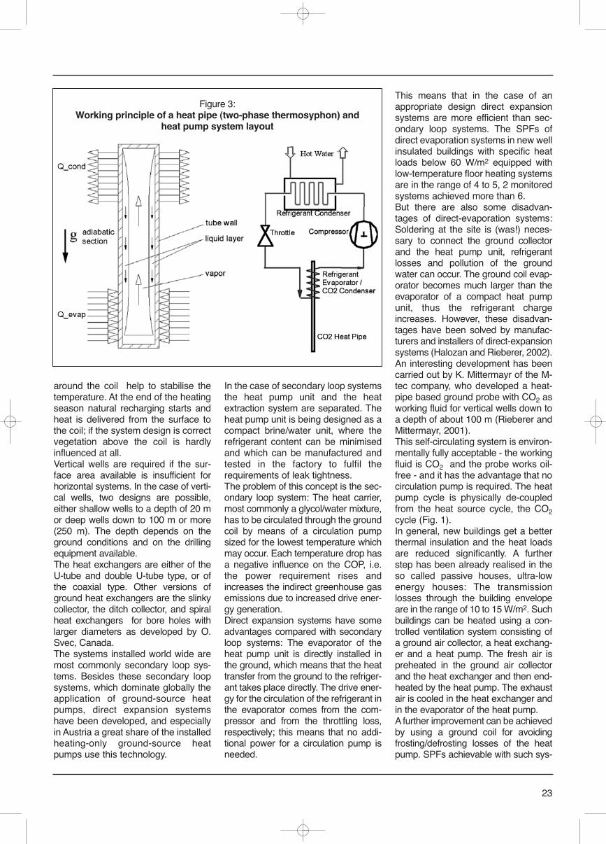
23
around the coil help to stabilise thetemperature. At the end of the heatingseason natural recharging starts andheat is delivered from the surface tothe coil; if the system design is correctvegetation above the coil is hardlyinfluenced at all.Vertical wells are required if the sur-face area available is insufficient forhorizontal systems. In the case of verti-cal wells, two designs are possible,either shallow wells to a depth of 20 mor deep wells down to 100 m or more(250 m). The depth depends on theground conditions and on the drillingequipment available.The heat exchangers are either of theU-tube and double U-tube type, or ofthe coaxial type. Other versions ofground heat exchangers are the slinkycollector, the ditch collector, and spiralheat exchangers for bore holes withlarger diameters as developed by O.Svec, Canada. The systems installed world wide aremost commonly secondary loop sys-tems. Besides these secondary loopsystems, which dominate globally theapplication of ground-source heatpumps, direct expansion systemshave been developed, and especiallyin Austria a great share of the installedheating-only ground-source heatpumps use this technology.
In the case of secondary loop systemsthe heat pump unit and the heatextraction system are separated. Theheat pump unit is being designed as acompact brine/water unit, where therefrigerant content can be minimisedand which can be manufactured andtested in the factory to fulfil therequirements of leak tightness. The problem of this concept is the sec-ondary loop system: The heat carrier,most commonly a glycol/water mixture,has to be circulated through the groundcoil by means of a circulation pumpsized for the lowest temperature whichmay occur. Each temperature drop hasa negative influence on the COP, i.e.the power requirement rises andincreases the indirect greenhouse gasemissions due to increased drive ener-gy generation.Direct expansion systems have someadvantages compared with secondaryloop systems: The evaporator of theheat pump unit is directly installed inthe ground, which means that the heattransfer from the ground to the refriger-ant takes place directly. The drive ener-gy for the circulation of the refrigerant inthe evaporator comes from the com-pressor and from the throttling loss,respectively; this means that no addi-tional power for a circulation pump isneeded.
This means that in the case of anappropriate design direct expansionsystems are more efficient than sec-ondary loop systems. The SPFs ofdirect evaporation systems in new wellinsulated buildings with specific heatloads below 60 W/m2 equipped withlow-temperature floor heating systemsare in the range of 4 to 5, 2 monitoredsystems achieved more than 6.But there are also some disadvan-tages of direct-evaporation systems:Soldering at the site is (was!) neces-sary to connect the ground collectorand the heat pump unit, refrigerantlosses and pollution of the groundwater can occur. The ground coil evap-orator becomes much larger than theevaporator of a compact heat pumpunit, thus the refrigerant chargeincreases. However, these disadvan-tages have been solved by manufac-turers and installers of direct-expansionsystems (Halozan and Rieberer, 2002). An interesting development has beencarried out by K. Mittermayr of the M-tec company, who developed a heat-pipe based ground probe with CO2 asworking fluid for vertical wells down toa depth of about 100 m (Rieberer andMittermayr, 2001).This self-circulating system is environ-mentally fully acceptable - the workingfluid is CO2 and the probe works oil-free - and it has the advantage that nocirculation pump is required. The heatpump cycle is physically de-coupledfrom the heat source cycle, the CO2cycle (Fig. 1). In general, new buildings get a betterthermal insulation and the heat loadsare reduced significantly. A furtherstep has been already realised in theso called passive houses, ultra-lowenergy houses: The transmissionlosses through the building envelopeare in the range of 10 to 15 W/m2. Suchbuildings can be heated using a con-trolled ventilation system consisting ofa ground air collector, a heat exchang-er and a heat pump. The fresh air ispreheated in the ground air collectorand the heat exchanger and then end-heated by the heat pump. The exhaustair is cooled in the heat exchanger andin the evaporator of the heat pump.A further improvement can be achievedby using a ground coil for avoidingfrosting/defrosting losses of the heatpump. SPFs achievable with such sys-
Figure 3:Working principle of a heat pipe (two-phase thermosyphon) and
heat pump system layout
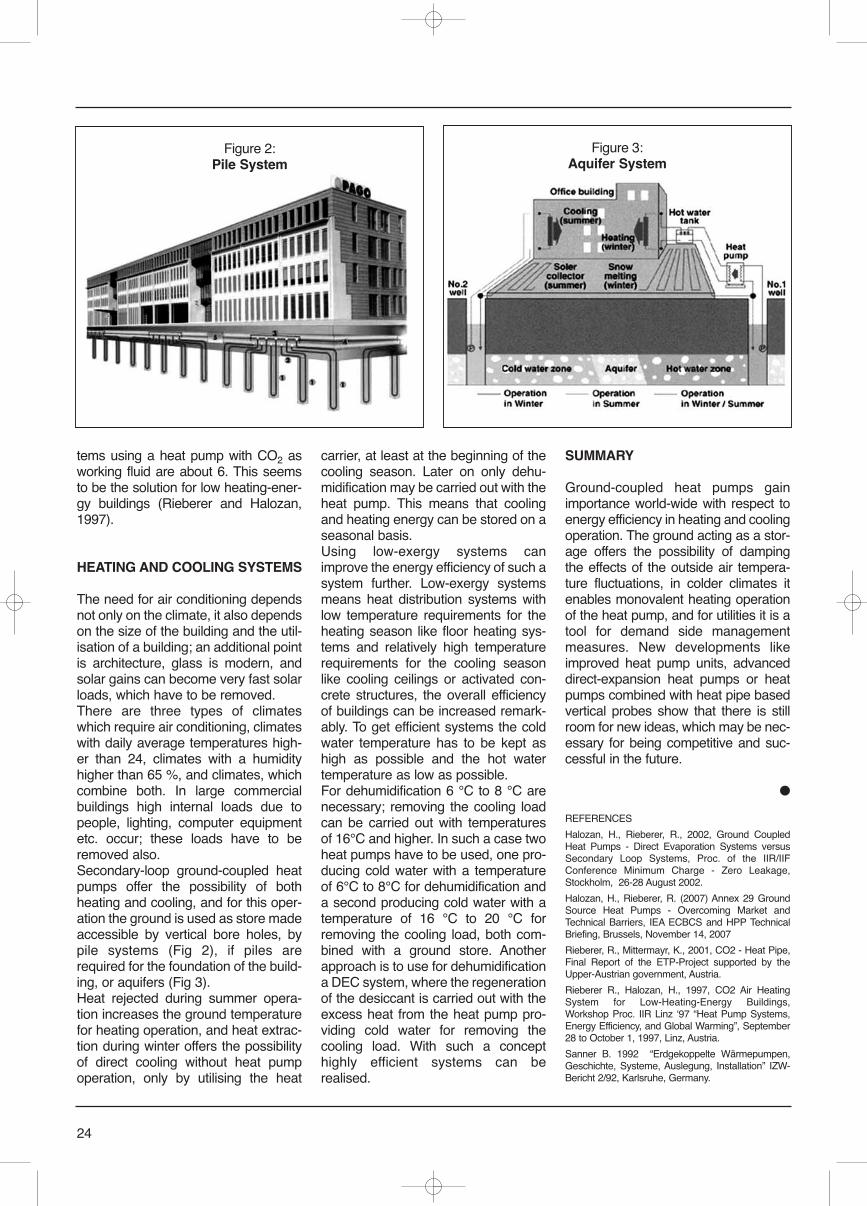
tems using a heat pump with CO2 asworking fluid are about 6. This seemsto be the solution for low heating-ener-gy buildings (Rieberer and Halozan,1997).
HEATING AND COOLING SYSTEMS
The need for air conditioning dependsnot only on the climate, it also dependson the size of the building and the util-isation of a building; an additional pointis architecture, glass is modern, andsolar gains can become very fast solarloads, which have to be removed.There are three types of climateswhich require air conditioning, climateswith daily average temperatures high-er than 24, climates with a humidityhigher than 65 %, and climates, whichcombine both. In large commercialbuildings high internal loads due topeople, lighting, computer equipmentetc. occur; these loads have to beremoved also.Secondary-loop ground-coupled heatpumps offer the possibility of bothheating and cooling, and for this oper-ation the ground is used as store madeaccessible by vertical bore holes, bypile systems (Fig 2), if piles arerequired for the foundation of the build-ing, or aquifers (Fig 3).Heat rejected during summer opera-tion increases the ground temperaturefor heating operation, and heat extrac-tion during winter offers the possibilityof direct cooling without heat pumpoperation, only by utilising the heat
carrier, at least at the beginning of thecooling season. Later on only dehu-midification may be carried out with theheat pump. This means that coolingand heating energy can be stored on aseasonal basis.Using low-exergy systems canimprove the energy efficiency of such asystem further. Low-exergy systemsmeans heat distribution systems withlow temperature requirements for theheating season like floor heating sys-tems and relatively high temperaturerequirements for the cooling seasonlike cooling ceilings or activated con-crete structures, the overall efficiencyof buildings can be increased remark-ably. To get efficient systems the coldwater temperature has to be kept ashigh as possible and the hot watertemperature as low as possible.For dehumidification 6 °C to 8 °C arenecessary; removing the cooling loadcan be carried out with temperaturesof 16°C and higher. In such a case twoheat pumps have to be used, one pro-ducing cold water with a temperatureof 6°C to 8°C for dehumidification anda second producing cold water with atemperature of 16 °C to 20 °C forremoving the cooling load, both com-bined with a ground store. Anotherapproach is to use for dehumidificationa DEC system, where the regenerationof the desiccant is carried out with theexcess heat from the heat pump pro-viding cold water for removing thecooling load. With such a concepthighly efficient systems can berealised.
SUMMARY
Ground-coupled heat pumps gainimportance world-wide with respect toenergy efficiency in heating and coolingoperation. The ground acting as a stor-age offers the possibility of dampingthe effects of the outside air tempera-ture fluctuations, in colder climates itenables monovalent heating operationof the heat pump, and for utilities it is atool for demand side managementmeasures. New developments likeimproved heat pump units, advanceddirect-expansion heat pumps or heatpumps combined with heat pipe basedvertical probes show that there is stillroom for new ideas, which may be nec-essary for being competitive and suc-cessful in the future.
●
REFERENCES
Halozan, H., Rieberer, R., 2002, Ground CoupledHeat Pumps - Direct Evaporation Systems versusSecondary Loop Systems, Proc. of the IIR/IIFConference Minimum Charge - Zero Leakage,Stockholm, 26-28 August 2002.
Halozan, H., Rieberer, R. (2007) Annex 29 GroundSource Heat Pumps - Overcoming Market andTechnical Barriers, IEA ECBCS and HPP TechnicalBriefing, Brussels, November 14, 2007
Rieberer, R., Mittermayr, K., 2001, CO2 - Heat Pipe,Final Report of the ETP-Project supported by theUpper-Austrian government, Austria.
Rieberer R., Halozan, H., 1997, CO2 Air HeatingSystem for Low-Heating-Energy Buildings,Workshop Proc. IIR Linz ʻ97 “Heat Pump Systems,Energy Efficiency, and Global Warming”, September28 to October 1, 1997, Linz, Austria.
Sanner B. 1992 “Erdgekoppelte Wärmepumpen,Geschichte, Systeme, Auslegung, Installation” IZW-Bericht 2/92, Karlsruhe, Germany.
24
Figure 2:Pile System
Figure 3:Aquifer System
The Montreal Protocol, within theframework of ozone-layer protection,limits the use and production of HCFCsaccording to the following time frame:- Year 2000: ban on charging of newequipment;- Year 2010: ban on recharging with vir-gin HCFCs;- Year 2015: ban on recharging withrecycled HCFCs.With the 2010 deadline just a matter ofmonths away, the ban on rechargingwith virgin HCFCs means that allchemical firms will have to stop manu-facturing these refrigerants. As aresult, only HCFCs derived fromrecovery will be available for mainte-nance purposes enabling existing air-conditioning and refrigeration equip-ment to remain in use.In France, the Montreal (ozone layer)and Kyoto (greenhouse gases)Protocols have been legally adopted ata national level and tightness control issubjected to objectives. The Frenchregulations are as follows:• Decree No. 2007-737 of May 7, 2007concerning certain refrigerants usedin refrigeration and air-conditioningequipment (published in the OfficialJournal of the French Republic onMay 8, 2007). • Decree of May 7, 2007 concerningthe tightness control of elementsensuring the containment of refriger-ants used in refrigeration and air-con-ditioning equipment (published in theOfficial Journal of the French Republicon May 8, 2007). This regulation will be completed by 4orders:
– Order concerning the providing ofcertificates governing the ability ofoperators as foreseen in Article 13 ofDecree No. 2007-737 of May 7, 2007;(this is the Decree of June 30, 2008published in the Official Journal of theFrench Republic on July 18, 2008).– Order concerning the approval oforganizations foreseen in Article 15 ofthe Decree No. 2007-737;– Order concerning the annual state-ment to be provided by authorizedorganizations, distributors of refriger-ants, manufacturers of refrigerants andequipment containing refrigerants;– Order concerning the frames of refer-ence for professional skills related tothe types of activities performed andthe types of equipment used, includingthe conditions under which certificatesgoverning competence are provided. A major issue has yet to be resolved:will the recovery of R22 provide suffi-cient quantities to enable all existingequipment to continue to operate? InFrance, existing equipment contains atotal of 25 000 tonnes of R22, andrecovery provides 300 tonnes per year.This means that the leakage rate wouldhave to be about 1% in order to offsetlosses through recovery. In fact, thecurrent leakage rate is roughly 10%.Users of equipment operating on R22have several options:- to carry on using R22 but to controlthe tightness of the equipment by mini-mizing all leakage;- to envisage retrofitting in order to useanother refrigerant;- to replace the equipment.UNICLIMA’s advice on how to plan
25
Phase-out of HCFCs:impact on air-conditioningand refrigeration systems operatingon R22
PATRICK ANTOINE, GUY-NOEL DUPRÉ
President Association Française du Froid AFF - Uniclima
The French Association ofRefrigeration (AFF), together withthe International Institute ofRefrigeration, founded in 1908, iscelebrating its 100th anniversaryand it is well known for theimportant initiative carried out bothat a national and at an internationallevel. The issue of new refrigerantshas often been analyzed by AFFand its previous presidents Mr.Louis Lucas and Mr. Michel Barth,especially during the EuropeanConferences organized by CentroStudi Galileo and with publicationsof interviews, articles anddocuments in the magazineIndustria & Formazione.
Patrick Antoine
The seat of AFF is the historical buildingfounded by Napoleon in 1801 as the first soci-ety for industrial promotion, in the historicalsquare of St. Germain des Près.
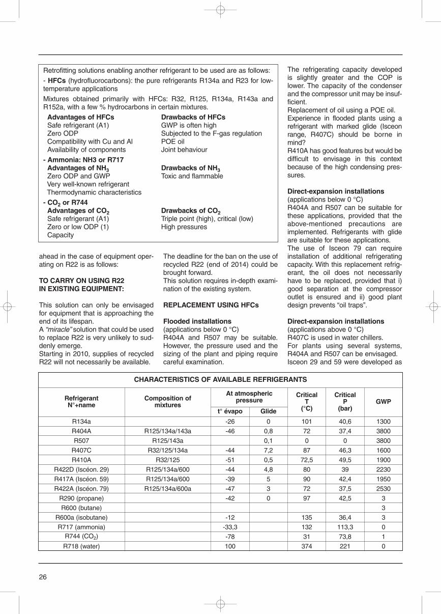
ahead in the case of equipment oper-ating on R22 is as follows:
TO CARRY ON USING R22IN EXISTING EQUIPMENT:
This solution can only be envisagedfor equipment that is approaching theend of its lifespan.A “miracle” solution that could be usedto replace R22 is very unlikely to sud-denly emerge.Starting in 2010, supplies of recycledR22 will not necessarily be available.
The deadline for the ban on the use ofrecycled R22 (end of 2014) could bebrought forward.This solution requires in-depth exami-nation of the existing system.
REPLACEMENT USING HFCs
Flooded installations(applications below 0 °C) R404A and R507 may be suitable.However, the pressure used and thesizing of the plant and piping requirecareful examination.
The refrigerating capacity developedis slightly greater and the COP islower. The capacity of the condenserand the compressor unit may be insuf-ficient.Replacement of oil using a POE oil.Experience in flooded plants using arefrigerant with marked glide (Isceonrange, R407C) should be borne inmind?R410A has good features but would bedifficult to envisage in this contextbecause of the high condensing pres-sures.
Direct-expansion installations(applications below 0 °C)R404A and R507 can be suitable forthese applications, provided that theabove-mentioned precautions areimplemented. Refrigerants with glideare suitable for these applications.The use of Isceon 79 can requireinstallation of additional refrigeratingcapacity. With this replacement refrig-erant, the oil does not necessarilyhave to be replaced, provided that i)good separation at the compressoroutlet is ensured and ii) good plantdesign prevents “oil traps”.
Direct-expansion installations(applications above 0 °C)R407C is used in water chillers.For plants using several systems,R404A and R507 can be envisaged.Isceon 29 and 59 were developed as
26
Retrofitting solutions enabling another refrigerant to be used are as follows:
- HFCs (hydrofluorocarbons): the pure refrigerants R134a and R23 for low-temperature applications
Mixtures obtained primarily with HFCs: R32, R125, R134a, R143a andR152a, with a few % hydrocarbons in certain mixtures.
Advantages of HFCs Drawbacks of HFCsSafe refrigerant (A1) GWP is often highZero ODP Subjected to the F-gas regulationCompatibility with Cu and Al POE oilAvailability of components Joint behaviour
- Ammonia: NH3 or R717 Advantages of NH3 Drawbacks of NH3Zero ODP and GWP Toxic and flammableVery well-known refrigerant Thermodynamic characteristics
- CO2 or R744Advantages of CO2 Drawbacks of CO2Safe refrigerant (A1) Triple point (high), critical (low)Zero or low ODP (1) High pressuresCapacity
CHARACTERISTICS OF AVAILABLE REFRIGERANTS
RefrigerantN°+name
R134a -26 0 101 40,6 1300
R404A R125/134a/143a -46 0,8 72 37,4 3800
R507 R125/143a 0,1 0 0 3800
R407C R32/125/134a -44 7,2 87 46,3 1600
R410A R32/125 -51 0,5 72,5 49,5 1900
R422D (Iscéon. 29) R125/134a/600 -44 4,8 80 39 2230
R417A (Iscéon. 59) R125/134a/600 -39 5 90 42,4 1950
R422A (Iscéon. 79) R125/134a/600a -47 3 72 37,5 2530
R290 (propane) -42 0 97 42,5 3
R600 (butane) 3
R600a (isobutane) -12 135 36,4 3
R717 (ammonia) -33,3 132 113,3 0R744 (CO2) -78 31 73,8 1
R718 (water) 100 374 221 0
Composition ofmixtures
At atmosphericpressure
t° évapo Glide
CriticalT
(°C)
CriticalP
(bar)GWP
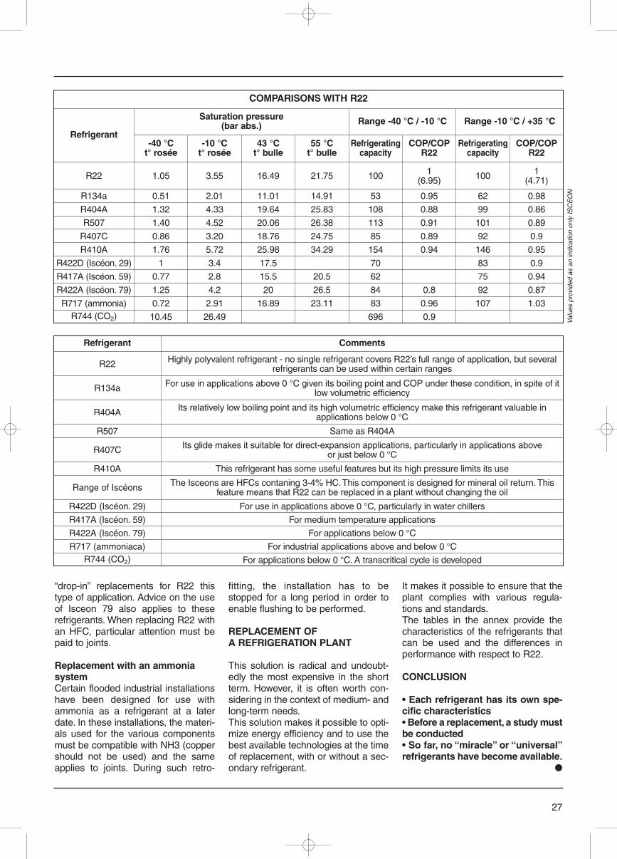
“drop-in” replacements for R22 thistype of application. Advice on the useof Isceon 79 also applies to theserefrigerants. When replacing R22 withan HFC, particular attention must bepaid to joints.
Replacement with an ammoniasystemCertain flooded industrial installationshave been designed for use withammonia as a refrigerant at a laterdate. In these installations, the materi-als used for the various componentsmust be compatible with NH3 (coppershould not be used) and the sameapplies to joints. During such retro-
fitting, the installation has to bestopped for a long period in order toenable flushing to be performed.
REPLACEMENT OFA REFRIGERATION PLANT
This solution is radical and undoubt-edly the most expensive in the shortterm. However, it is often worth con-sidering in the context of medium- andlong-term needs.This solution makes it possible to opti-mize energy efficiency and to use thebest available technologies at the timeof replacement, with or without a sec-ondary refrigerant.
It makes it possible to ensure that theplant complies with various regula-tions and standards. The tables in the annex provide thecharacteristics of the refrigerants thatcan be used and the differences inperformance with respect to R22.
CONCLUSION
• Each refrigerant has its own spe-cific characteristics• Before a replacement, a study mustbe conducted• So far, no “miracle” or “universal”refrigerants have become available.
●
27
Refrigerant Comments
R22 Highly polyvalent refrigerant - no single refrigerant covers R22’s full range of application, but severalrefrigerants can be used within certain ranges
R134a For use in applications above 0 °C given its boiling point and COP under these condition, in spite of itlow volumetric efficiency
R404A Its relatively low boiling point and its high volumetric efficiency make this refrigerant valuable inapplications below 0 °C
R507 Same as R404A
R407C Its glide makes it suitable for direct-expansion applications, particularly in applications aboveor just below 0 °C
R410A This refrigerant has some useful features but its high pressure limits its use
Range of Iscéons The Isceons are HFCs contaning 3-4% HC. This component is designed for mineral oil return. Thisfeature means that R22 can be replaced in a plant without changing the oil
R422D (Iscéon. 29) For use in applications above 0 °C, particularly in water chillers
R417A (Iscéon. 59) For medium temperature applications
R422A (Iscéon. 79) For applications below 0 °C
R717 (ammoniaca) For industrial applications above and below 0 °CR744 (CO2) For applications below 0 °C. A transcritical cycle is developed
COMPARISONS WITH R22
Refrigerant
R22 1.05 3.55 16.49 21.75 100 1(6.95) 100 1
(4.71)
R134a 0.51 2.01 11.01 14.91 53 0.95 62 0.98
R404A 1.32 4.33 19.64 25.83 108 0.88 99 0.86
R507 1.40 4.52 20.06 26.38 113 0.91 101 0.89
R407C 0.86 3.20 18.76 24.75 85 0.89 92 0.9
R410A 1.76 5.72 25.98 34.29 154 0.94 146 0.95
R422D (Iscéon. 29) 1 3.4 17.5 70 83 0.9
R417A (Iscéon. 59) 0.77 2.8 15.5 20.5 62 75 0.94
R422A (Iscéon. 79) 1.25 4.2 20 26.5 84 0.8 92 0.87
R717 (ammonia) 0.72 2.91 16.89 23.11 83 0.96 107 1.03R744 (CO2) 10.45 26.49 696 0.9
Saturation pressure(bar abs.) Range -40 °C / -10 °C Range -10 °C / +35 °C
-40 °Ct° rosée
-10 °Ct° rosée
43 °Ct° bulle
55 °Ct° bulle
Refrigeratingcapacity
COP/COPR22
Refrigeratingcapacity
COP/COPR22
Valu
es p
rovi
ded
as a
n in
dica
tion
only
ISC
EO
N
28
In January, 2008, the Air-Conditioning and RefrigerationInstitute (ARI) and the GasAppliance ManufacturersAssociation (GAMA) merged toform the Air-Conditioning,Heating, and RefrigerationInstitute (AHRI). AHRI is the tradeassociation representingmanufacturers of air conditioning,heating and commercialrefrigeration equipment. AHRIʼs350+ member companies accountfor more than 90 percent of theresidential and commercial airconditioning, space heating, waterheating, and commercialrefrigeration equipmentmanufactured and sold in NorthAmerica. AHRIʼs principalactivities are advocacy, thedevelopment of productstandards, the administration ofproduct performance certificationprograms and research.
The HVACR market in the U.S. isunique. Traditional building practicesand the style of living both lead toappliances and heating and coolingequipment that are sometimes differ-ent than the rest of the world. Forexample, Americans tend to shop forgroceries only one or two times aweek and store them for longer peri-ods, thus necessitating larger refriger-ators. The refrigerant charge (averag-ing around 0.3 kg) and amount offoam used for insulation is alsogreater than in most other parts of the
world. Refrigerant 134a is used exclu-sively for the household refrigerators. Most homes in the U.S. employ cen-tral comfort conditioning systems,generally both heating and cooling.U.S. Government data shows thattwo-thirds of all homes in the UnitedStates have central air conditionersand that about 90% of single familyand multi-family buildings built after2004 have air-conditioning [1].Residential air conditioners use about5% of all the electricity produced in theUnited States [2]. For homes andbuildings where central air condition-ers were not originally or cannot befeasibly installed, room or window airconditioners are commonly employed.Ductless systems, also called mini-split air conditioners, common in mostof the world, have been less commonin the U.S although a bit moreso inrecent years.The common application is as retrofitadd-ons to houses with “non-ducted”heating systems, such as hydronic(hot water heat) heating systems [2].In U.S., a majority of homes are heat-ed by either furnaces or boilers. Splitsystem reversible heat pumpswith/without supplementary heatingdevices are also common. Around29% of single family homes and 35%of units in multi-family buildings builtduring past five years have heat pumpsystems [1]. These systems have typ-ically used HCFC-22 and new sys-tems are transitioning to HFC-410A,but only about one-third of currentshipments contain 410A. In commercial buildings, a variety of
heating and cooling systems areemployed. There are many arrange-ments of air-to-air systems, includingrooftop unitary, package terminalequipment, and single package verti-cal units. All have used HCFC-22.Water source heat pumps haveincreased in popularity as have smallchillers. In larger buildings, chillerspredominate. High-pressure chillersuse HCFC-22 and HFC-134a, andlow-pressure chillers use HCFC-123.The breakdown of the energy use ofcommercial cooling equipment is illus-trated in Figure 1. Packaged air-condi-tioning units (mostly rooftop units)consume more than half of the totalenergy in the commercial cooling sec-tor. Chillers use 31% of total energy incommercial cooling sector.Overall, U.S. residential and commer-cial air-conditioning have greatly reliedon HCFC-22. However, under theClean Air Act, the production andimport of newly manufactured equip-ment utilizing HCFC-22 will stop in theUnited States by January 1, 2010.The production and import of HCFC-22 will be banned entirely in the UnitedStates by January 1, 2020. Once thishappens, only recycled/reclaimed orstockpiled quantities of HCFC-22 willbe available for servicing existingequipment [3]. At that time, the avail-ability of HCFC-22 is expected todecrease, and the price is expected toincrease as will the cost of service andmaintenance for old systems usingHCFC-22. Table 1 shows a list of themost common types of refrigerantsused for different equipment types and
Speciale
Refrigerant Use and EmissionReduction in the U.S.: 2008
MARK MENZER, XUDONG WANG
AHRI Air-Conditioning, Heating and Refrigeration InstituteMark Menzer
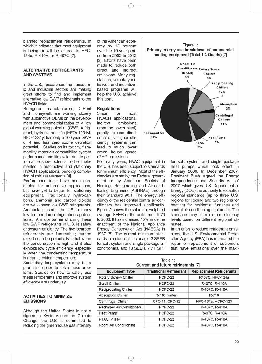
planned replacement refrigerants, inwhich it indicates that most equipmentis being or will be altered to HFC-134a, R-410A, or R-407C [7].
ALTERNATIVE REFRIGERANTSAND SYSTEMS
In the U.S., researchers from academ-ic and industrial sectors are makinggreat efforts to find and implementalternative low GWP refrigerants to theHVACR fields. Refrigerant manufacturers, DuPontand Honeywell, are working closelywith automotive OEMs on the develop-ment and commercialization of a lowglobal warming potential (GWP) refrig-erant, hydrofluoro-olefin (HFO)-1234yf.HFO-1234yf has only a 100 year GWPof 4 and has zero ozone depletionpotential. Studies on its toxicity, flam-mability, materials compatibility, systemperformance and life cycle climate per-formance show potential to be imple-mented in automotive and stationaryHVACR applications, pending comple-tion of risk assessments [4]. Performance tests have been con-ducted for automotive applications,but have yet to begun for stationaryequipment. Traditionally, hydrocar-bons, ammonia and carbon dioxideare well-known low GWP refrigerants.Ammonia is used in the U.S. for manylow temperature refrigeration applica-tions. A major barrier of using theselow GWP refrigerants in U.S. is safetyor system efficiency. The hydrocarbonrefrigerants are flammable; carbondioxide can be potentially lethal whenthe concentration is high and it alsoexhibits low cycle efficiency, especial-ly when the condensing temperatureis near its critical temperature.Secondary loop systems may be apromising option to solve these prob-lems. Studies on how to safely usethese refrigerants and improve systemefficiency are underway.
ACTIVITIES TO MINIMIZEEMISSIONS
Although the United States is not asignee to Kyoto Accord on ClimateChange, the U.S. is committed toreducing the greenhouse gas intensity
of the American econ-omy by 18 percentover the 10-year peri-od from 2002 to 2012[3]. Efforts have beenmade to reduce bothdirect and indirectemissions. Many reg-ulations, voluntary ini-tiatives and incentive-based programs willhelp the U.S. achievethis goal.
RegulationsSince, for mostHVACR applications,indirect emissions(from the power plant)greatly exceed directemissions, higher effi-ciency systems canlead to much lowergreen house gases(GHG) emissions. For many years, HVAC equipment inthe U.S. has been subject to standardsfor minimum efficiency. Most of the effi-ciencies are set by the Federal govern-ment or by American Society ofHeating, Refrigerating and Air-condi-tioning Engineers (ASHRAE) throughtheir Standard 90.1. The energy effi-ciency of the residential central air-con-ditioners has improved significantly.Figure 2 shows the shipment-weightedaverage SEER of the units from 1970to 2006. It has increased 45% since theenactment of the National ApplianceEnergy Conservation Act (NAECA) in1987 [8]. The current minimum stan-dards in residential sector are 13 SEERfor split system and single package airconditioners, and 13 SEER, 7.7 HSPF
for split system and single packageheat pumps which took effect inJanuary 2006. In December 2007,President Bush signed the EnergyIndependence and Security Act of2007, which gives U.S. Department ofEnergy (DOE) the authority to establishregional standards (up to three U.S.regions for cooling and two regions forheating) for residential furnaces andcentral air conditioning equipment. Thestandards may set minimum efficiencylevels based on different regional cli-mates. In an effort to reduce refrigerant emis-sions, the U.S. Environmental Prote-ction Agency (EPA) has mandated therepair or replacement of equipmentthat have emissions over the maxi-
29
Figure 1:Primary energy use breakdown of commercial
cooling equipment (Total 1.4 Quads) [7]
Table 1:Current and future refrigerants [7]
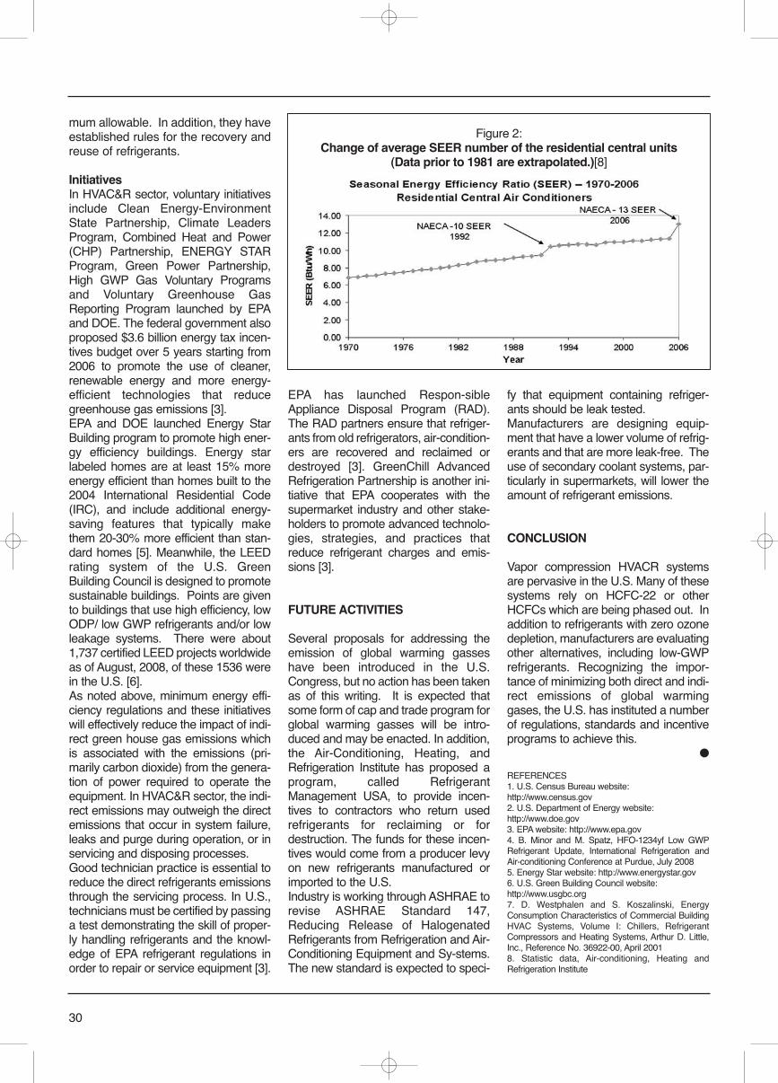
mum allowable. In addition, they haveestablished rules for the recovery andreuse of refrigerants.
InitiativesIn HVAC&R sector, voluntary initiativesinclude Clean Energy-EnvironmentState Partnership, Climate LeadersProgram, Combined Heat and Power(CHP) Partnership, ENERGY STARProgram, Green Power Partnership,High GWP Gas Voluntary Programsand Voluntary Greenhouse GasReporting Program launched by EPAand DOE. The federal government alsoproposed $3.6 billion energy tax incen-tives budget over 5 years starting from2006 to promote the use of cleaner,renewable energy and more energy-efficient technologies that reducegreenhouse gas emissions [3]. EPA and DOE launched Energy StarBuilding program to promote high ener-gy efficiency buildings. Energy starlabeled homes are at least 15% moreenergy efficient than homes built to the2004 International Residential Code(IRC), and include additional energy-saving features that typically makethem 20-30% more efficient than stan-dard homes [5]. Meanwhile, the LEEDrating system of the U.S. GreenBuilding Council is designed to promotesustainable buildings. Points are givento buildings that use high efficiency, lowODP/ low GWP refrigerants and/or lowleakage systems. There were about1,737 certified LEED projects worldwideas of August, 2008, of these 1536 werein the U.S. [6].As noted above, minimum energy effi-ciency regulations and these initiativeswill effectively reduce the impact of indi-rect green house gas emissions whichis associated with the emissions (pri-marily carbon dioxide) from the genera-tion of power required to operate theequipment. In HVAC&R sector, the indi-rect emissions may outweigh the directemissions that occur in system failure,leaks and purge during operation, or inservicing and disposing processes.Good technician practice is essential toreduce the direct refrigerants emissionsthrough the servicing process. In U.S.,technicians must be certified by passinga test demonstrating the skill of proper-ly handling refrigerants and the knowl-edge of EPA refrigerant regulations inorder to repair or service equipment [3].
EPA has launched Respon-sibleAppliance Disposal Program (RAD).The RAD partners ensure that refriger-ants from old refrigerators, air-condition-ers are recovered and reclaimed ordestroyed [3]. GreenChill AdvancedRefrigeration Partnership is another ini-tiative that EPA cooperates with thesupermarket industry and other stake-holders to promote advanced technolo-gies, strategies, and practices thatreduce refrigerant charges and emis-sions [3].
FUTURE ACTIVITIES
Several proposals for addressing theemission of global warming gasseshave been introduced in the U.S.Congress, but no action has been takenas of this writing. It is expected thatsome form of cap and trade program forglobal warming gasses will be intro-duced and may be enacted. In addition,the Air-Conditioning, Heating, andRefrigeration Institute has proposed aprogram, called RefrigerantManagement USA, to provide incen-tives to contractors who return usedrefrigerants for reclaiming or fordestruction. The funds for these incen-tives would come from a producer levyon new refrigerants manufactured orimported to the U.S. Industry is working through ASHRAE torevise ASHRAE Standard 147,Reducing Release of HalogenatedRefrigerants from Refrigeration and Air-Conditioning Equipment and Sy-stems.The new standard is expected to speci-
fy that equipment containing refriger-ants should be leak tested.Manufacturers are designing equip-ment that have a lower volume of refrig-erants and that are more leak-free. Theuse of secondary coolant systems, par-ticularly in supermarkets, will lower theamount of refrigerant emissions.
CONCLUSION
Vapor compression HVACR systemsare pervasive in the U.S. Many of thesesystems rely on HCFC-22 or otherHCFCs which are being phased out. Inaddition to refrigerants with zero ozonedepletion, manufacturers are evaluatingother alternatives, including low-GWPrefrigerants. Recognizing the impor-tance of minimizing both direct and indi-rect emissions of global warminggases, the U.S. has instituted a numberof regulations, standards and incentiveprograms to achieve this.
●
REFERENCES1. U.S. Census Bureau website:http://www.census.gov2. U.S. Department of Energy website:http://www.doe.gov3. EPA website: http://www.epa.gov4. B. Minor and M. Spatz, HFO-1234yf Low GWPRefrigerant Update, International Refrigeration andAir-conditioning Conference at Purdue, July 20085. Energy Star website: http://www.energystar.gov6. U.S. Green Building Council website:http://www.usgbc.org7. D. Westphalen and S. Koszalinski, EnergyConsumption Characteristics of Commercial BuildingHVAC Systems, Volume I: Chillers, RefrigerantCompressors and Heating Systems, Arthur D. Little,Inc., Reference No. 36922-00, April 20018. Statistic data, Air-conditioning, Heating andRefrigeration Institute
30
Figure 2:Change of average SEER number of the residential central units
(Data prior to 1981 are extrapolated.)[8]

INTRODUCTION
Ammonia is a common, cheap inor-ganic compound and is also a naturalrefrigerant (R717). Due to its goodthermodynamic properties and thefact that it does not harm the atmos-phere, it plays an important role in thedevelopment of refrigeration technolo-gies. At present, ammonia is not ableto be used in household or air-condi-tioning systems because of its toxicityand explosion potential at certain airconcentrations, but is mainly used inlarge-scale industrial refrigeration andcommercial frozen storage.In recent years, everyone has recog-nized the international consensus ofthe CFC phase-out and reduction ofHCFCs based on the fact that fluoro-carbon refrigerants destroy the ozonelayer and generate the greenhouseeffect. Today we are trying to find newrefrigerants which are not harmful tothe ozone layer and do not contributeto the greenhouse effect, and we areputting more attention on naturalrefrigerants. Technicians have alreadybegun exerting their efforts revaluatingand researching ammonia safety, sys-tems and equipment.Some ammonia equipment with keytechnology and control units havebeen developed and put into massproduction, which creates favorableconditions for the promotion of ammo-nia refrigeration technology. How tospeed up the research and applicationof ammonia systems is becoming akey subject of refrigeration sharehold-ers all over the world.
As an environmentally-friendly refrig-erant, ammonia is becoming popularin China, but will not completelyreplace CFC and HCFC refrigerants inrecent years
MAIN CHARACTERISTICS
Excellent environmental andthermodynamic propertiesAmmonia is a natural medium-temper-ature refrigerant with excellent environ-mental and thermodynamic properties:1) ODP=0, GWP=0, an environmen-tally-friendly refrigerant.2) Critical temperature is 132.3°C, criti-cal pressure is 11.33MPa, higher thanthat of R22 (96.2 °C/4.99MPa) andR410A (70.2 °C/4.79MPa)[1]. Standardboiling temperature is low (-33.4 °C),large volumetric refrigerating capaci-ty, high conductivity coefficient, highevaporative latent heat (6.4 timesthat of R22, 5.5 times that of R410Aat -15 °C), low throttling loss, highrefrigeration coefficient, smaller size ofcompressors and heat exchangerscompared with that of R22 at the sametemperature and refrigerating capacity. 3) Molecular weight is 17, vapor den-sity is lower than that of air, it easilyrises and escapes from the roof whenleakage occurs, easily dissolves inwater during a large leakage.4) Easily purchased at a low price, thecharge cost is about 1/10 that of R22for the same volume.
DisadvantagesAmmonia was replaced by fluorocar-bons to some extent for a period of
31
Development Trends ofAmmonia Refrigeration Technology
YANG YIFAN and HU WANGYANG
Chinese Association of Refrigeration
Chinese Association ofRefrigeration (CAR) was foundedon April 25 th , 1977. CAR is anational scientific organization inthe field of refrigeration and air-conditioning industry and trade,which is subordinated to ChinaAssociation for Science andTechnology (CAST). CAR formallyjoined in the International Instituteof Refrigeration (IIR) in January1978, and became a second grademembership country. CAR alwaysaims at solidifying and serving itsmembers and technical personnel,and developing the science andtechnology of China refrigeration.In response to the global needs ofprotecting the ozone layer andreducing the greenhouse effect,CFC refrigerants are being phasedout because they destroy theatmosphere and cause thegreenhouse effect, and the use ofHCFC refrigerants is beinggradually limited. This paperanalyzes the properties andapplication history of ammonia, anenvironmentally-friendly refrigerant(ODP=0, GWP=0), and predicts thedevelopment trends and futureproblems of ammonia refrigerationtechnology based on ammoniarefrigeration system optimization,control technology, safety, systemminiaturization, etc.Keywords: Refrigerant, ammoniarefrigeration system, safety,development trends.
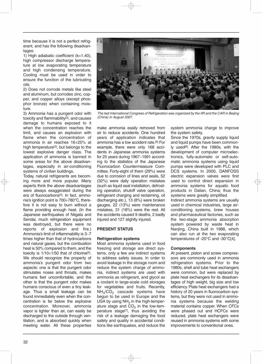
time because it is not a perfect refrig-erant, and has the following disadvan-tages:1) High adiabatic coefficient (k=1.40),high compressor discharge tempera-ture at low evaporating temperatureand high condensing temperature.Cooling must be used in order toensure the function of the lubricatingoils.2) Does not corrode metals like steeland aluminum, but corrodes zinc, cop-per, and copper alloys (except phos-phor bronze) when containing mois-ture.3) Ammonia has a pungent odor withtoxicity and flammability[2], and causesdamage to humans exposed to itwhen the concentration reaches thelimit, and causes an explosion withflame when the concentration ofammonia in air reaches 16÷25% athigh temperature[3], but belongs to thelowest explosive danger class. Theapplication of ammonia is banned insome areas for the above disadvan-tages, especially in air-conditioningsystems of civilian buildings. Today, natural refrigerants are becom-ing more and more popular. Manyexperts think the above disadvantageswere always exaggerated during theera of fluorocarbons[4]. In fact, ammo-nia’s ignition point is 700÷780°C, there-fore it is not easy to burn without aflame providing enough heat. (In theJapanese earthquakes of Niigata andSendai, much refrigeration equipmentwas destroyed, but there were noreports of explosion and fire.)Ammonia’s limit of inflammability is 3~7times higher than that of hydrocarbonsand natural gases, but the combustionheat is 50% compared to them, and thetoxicity is 1/10÷1/50 that of chlorine[5].We should recognize the property ofammonia’s pungent odor from twoaspects: one is that the pungent odorstimulates noses and throats, makeshumans feel uncomfortable, and theother is that the pungent odor makeshumans conscious of even a tiny leak-age. Thus a small leakage can befound immediately even when the con-centration is far below the explosiveconcentration. Moreover, ammoniavapor is lighter than air, can easily bedischarged to the outside through ven-tilation, and is absorbed quickly whenmeeting water. All these properties
make ammonia easily removed fromair to reduce accidents. One hundredyears of application indicates thatammonia has a low accident rate.[6] Forexample, there were only 168 acci-dents in Japanese ammonia systemsfor 25 years during 1967~1991 accord-ing to the statistics of the JapaneseFluorocarbon Countermeasure Com-mittee. Forty-eight of them (29%) weredue to corrosion of lines and seals, 52(32%) were daily operation mistakes(such as liquid seal installation, defrost-ing operation, shutoff valve operation,refrigerant charging and reclaiming, oildischarging etc.), 13 (8%) were brokengauges, 22 (13%) were maintenancemistakes, 31 (18%) were the rest. Allthe accidents caused 9 deaths, 2 badlyinjured and 127 slightly injured.
PRESENT STATUS
Refrigeration systemsMost ammonia systems used in foodfreezing and storage are direct sys-tems, only a few are indirect systemsto address safety issues. In order toavoid leakage in the storage room andreduce the system charge of ammo-nia, indirect systems are used withammonia as refrigerant, and glycol asa coolant in large-scale cold storagesfor vegetables and fruits. Recently,NH3/CO2 cascade systems havebegun to be used in Europe and theUSA by using NH3 in the high-temper-ature stage and CO2 in the low-tem-perature stage[7], thus avoiding therisk of a leakage damaging the foodsafety and quality in accidental condi-tions like earthquakes, and reduce the
system ammonia charge to improvethe system safety.Since the 1970s, gravity supply liquidand liquid pumps have been common-ly used[8]. After the 1980s, with thedevelopment of computer microelec-tronics, fully-automatic or self-auto-matic ammonia systems using liquidpumps were developed with PLC andDCS systems. In 2000, DANFOSSelectric expansion valves were firstused to control direct expansion inammonia systems for aquatic foodproducts in Dalian, China; thus thesystems were greatly simplified.Indirect ammonia systems are usuallyused in chemical industries, large air-conditioning systems, brew housesand pharmaceutical factories, such asthe two-stage ammonia absorptionsystem powered by waste heat inNanjing, China built in 1988, whichcan also run at the two evaporatingtemperatures of -20°C and -30°C[4].
ComponentsAt present, piston and screw compres-sors are commonly used in ammoniarefrigeration systems. Prior to the1980s, shell and tube heat exchangerswere common, but were replaced byplate heat exchangers for its disadvan-tages of high weight, big size and lowefficiency. Plate heat exchangers had ahistory of 20 years in fluorocarbon sys-tems, but they were not used in ammo-nia systems because the weldingmaterial contains copper. When CFCswere phased out and HCFCs werereduced, plate heat exchangers werereused in ammonia systems with someimprovements to conventional ones.
32
The last International Congress of Refrigeration was organized by the IIR and the CAR in Beijing(China) in August 2007.
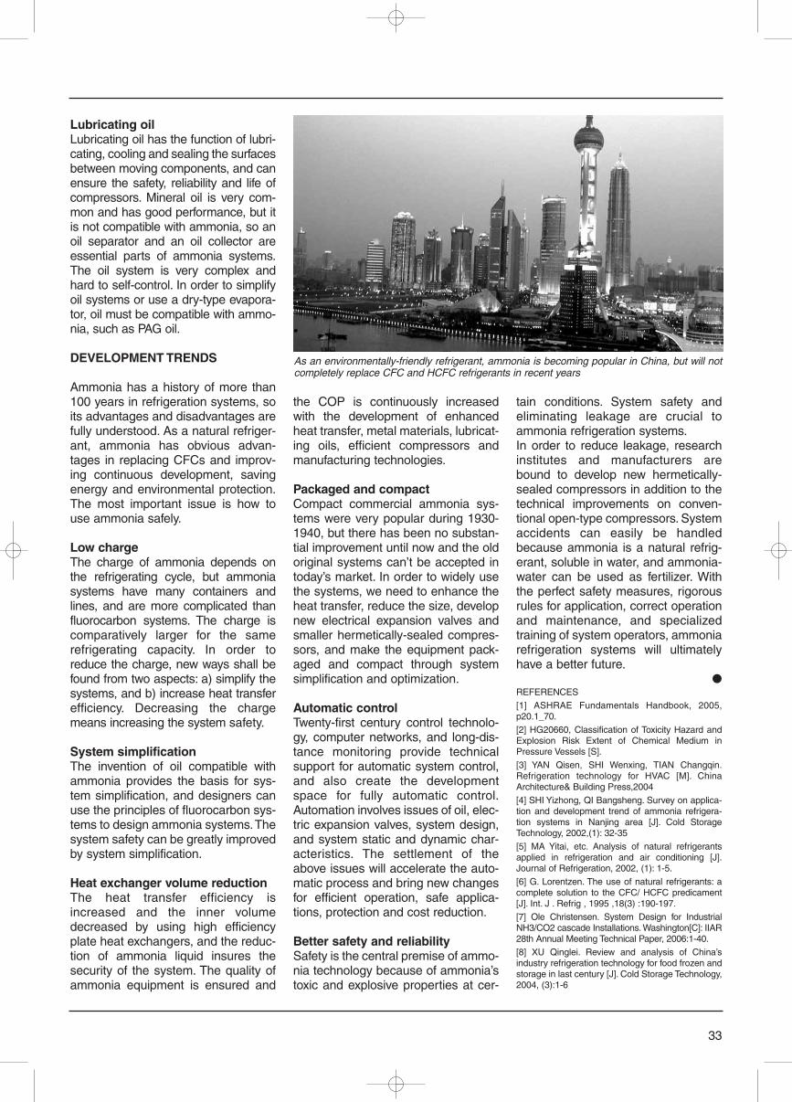
Lubricating oil Lubricating oil has the function of lubri-cating, cooling and sealing the surfacesbetween moving components, and canensure the safety, reliability and life ofcompressors. Mineral oil is very com-mon and has good performance, but itis not compatible with ammonia, so anoil separator and an oil collector areessential parts of ammonia systems.The oil system is very complex andhard to self-control. In order to simplifyoil systems or use a dry-type evapora-tor, oil must be compatible with ammo-nia, such as PAG oil.
DEVELOPMENT TRENDS
Ammonia has a history of more than100 years in refrigeration systems, soits advantages and disadvantages arefully understood. As a natural refriger-ant, ammonia has obvious advan-tages in replacing CFCs and improv-ing continuous development, savingenergy and environmental protection.The most important issue is how touse ammonia safely.
Low charge The charge of ammonia depends onthe refrigerating cycle, but ammoniasystems have many containers andlines, and are more complicated thanfluorocarbon systems. The charge iscomparatively larger for the samerefrigerating capacity. In order toreduce the charge, new ways shall befound from two aspects: a) simplify thesystems, and b) increase heat transferefficiency. Decreasing the chargemeans increasing the system safety.
System simplificationThe invention of oil compatible withammonia provides the basis for sys-tem simplification, and designers canuse the principles of fluorocarbon sys-tems to design ammonia systems. Thesystem safety can be greatly improvedby system simplification.
Heat exchanger volume reduction The heat transfer efficiency isincreased and the inner volumedecreased by using high efficiencyplate heat exchangers, and the reduc-tion of ammonia liquid insures thesecurity of the system. The quality ofammonia equipment is ensured and
the COP is continuously increasedwith the development of enhancedheat transfer, metal materials, lubricat-ing oils, efficient compressors andmanufacturing technologies.
Packaged and compact Compact commercial ammonia sys-tems were very popular during 1930-1940, but there has been no substan-tial improvement until now and the oldoriginal systems can’t be accepted intoday’s market. In order to widely usethe systems, we need to enhance theheat transfer, reduce the size, developnew electrical expansion valves andsmaller hermetically-sealed compres-sors, and make the equipment pack-aged and compact through systemsimplification and optimization.
Automatic controlTwenty-first century control technolo-gy, computer networks, and long-dis-tance monitoring provide technicalsupport for automatic system control,and also create the developmentspace for fully automatic control.Automation involves issues of oil, elec-tric expansion valves, system design,and system static and dynamic char-acteristics. The settlement of theabove issues will accelerate the auto-matic process and bring new changesfor efficient operation, safe applica-tions, protection and cost reduction.
Better safety and reliability Safety is the central premise of ammo-nia technology because of ammonia’stoxic and explosive properties at cer-
tain conditions. System safety andeliminating leakage are crucial toammonia refrigeration systems.In order to reduce leakage, researchinstitutes and manufacturers arebound to develop new hermetically-sealed compressors in addition to thetechnical improvements on conven-tional open-type compressors. Systemaccidents can easily be handledbecause ammonia is a natural refrig-erant, soluble in water, and ammonia-water can be used as fertilizer. Withthe perfect safety measures, rigorousrules for application, correct operationand maintenance, and specializedtraining of system operators, ammoniarefrigeration systems will ultimatelyhave a better future.
●REFERENCES
[1] ASHRAE Fundamentals Handbook, 2005,p20.1_70.
[2] HG20660, Classification of Toxicity Hazard andExplosion Risk Extent of Chemical Medium inPressure Vessels [S].
[3] YAN Qisen, SHI Wenxing, TIAN Changqin.Refrigeration technology for HVAC [M]. ChinaArchitecture& Building Press,2004
[4] SHI Yizhong, QI Bangsheng. Survey on applica-tion and development trend of ammonia refrigera-tion systems in Nanjing area [J]. Cold StorageTechnology, 2002,(1): 32-35
[5] MA Yitai, etc. Analysis of natural refrigerantsapplied in refrigeration and air conditioning [J].Journal of Refrigeration, 2002, (1): 1-5.
[6] G. Lorentzen. The use of natural refrigerants: acomplete solution to the CFC/ HCFC predicament[J]. Int. J . Refrig , 1995 ,18(3) :190-197.
[7] Ole Christensen. System Design for IndustrialNH3/CO2 cascade Installations. Washington[C]: IIAR28th Annual Meeting Technical Paper, 2006:1-40.
[8] XU Qinglei. Review and analysis of China’sindustry refrigeration technology for food frozen andstorage in last century [J]. Cold Storage Technology,2004, (3):1-6
33
As an environmentally-friendly refrigerant, ammonia is becoming popular in China, but will notcompletely replace CFC and HCFC refrigerants in recent years
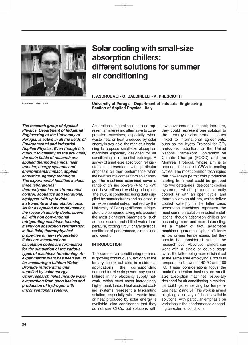
34
Absorption refrigerating machines rep-resent an interesting alternative to com-pression machines, especially whenwaste heat or heat produced by solarenergy is available; the market is begin-ning to propose small-size absorptionmachines especially designed for airconditioning in residential buildings. Asurvey of small-size absorption refriger-ators is presented, with particularemphasis on their performance whenthe heat source comes from solar ener-gy. The machines examined cover arange of chilling powers (4 to 15 kW)and have different working principles.The study is conducted using data sup-plied by manufacturers and collected inan experimental set-up realized by theUniversity of Perugia; different refriger-ators are compared taking into accountthe most significant parameters, suchas heat source and chilled water tem-perature, cooling circuit characteristics,coefficient of performance, dimensionsand weight.
INTRODUCTION
The summer air conditioning demandis growing continuously, not only in thetertiary sector but also in residentialapplications; the correspondingdemand for electric power may causefailures in the electricity supply net-work, which must cover increasinglyhigher peak loads. Heat assisted cool-ing systems represent a fascinatingsolution, especially when waste heator heat produced by solar energy isavailable, also considering that theydo not use CFCs, but solutions with
low environmental impact; therefore,they could represent one solution tothe energy-environmental issueslinked to international agreements,such as the Kyoto Protocol for CO2emissions reduction, or the UnitedNations Framework Convention onClimate Change (FCCC) and theMontreal Protocol, whose aim is toabandon the use of CFCs in coolingcycles. The most common techniquesthat nowadays permit cold productionstarting from heat could be groupedinto two categories: desiccant coolingsystems, which produce directlycooled air with an open cycle, andthermally driven chillers, which delivercooled water[1]. In the latter case,absorption machines represent themost common solution in actual instal-lations, though adsorption chillers arebecoming more and more interesting.As a matter of fact, adsorptionmachines guarantee higher efficiencyat low driving temperatures, but theyshould be considered still at theresearch level. Absorption chillers canwork with a single or double stagecycle, the latter being more efficient butat the same time employing a hot fluidtemperature between 140 °C and 160°C. These considerations focus themarketʼs attention basically on small-size absorption machines, especiallydesigned for air conditioning in residen-tial buildings, employing low tempera-ture heat [2 and 3]. This work is aimedat giving a survey of these availablesolutions, with particular emphasis onvariations in their performance depend-ing on external conditions.
Solar cooling with small-sizeabsorption chillers:different solutions for summerair conditioning
F. ASDRUBALI - G. BALDINELLI - A. PRESCIUTTI
University of Perugia - Department of Industrial EngineeringSection of Applied Physics - Italy
The research group of AppliedPhysics, Department of IndustrialEngineering of the University ofPerugia, is active in all the fields ofEnvironmental and IndustrialApplied Physics. Even though it isdifficult to classify all the activities,the main fields of research areapplied thermodynamics, heattransfer, energy systems andenvironmental impact, appliedacoustics, lighting technique. The experimental facilities includethree laboratories:thermodynamics, environmentalcontrol, acoustics and vibrations,equipped with up to dateinstruments and simulation tools.As far as applied thermodynamics,the research activity deals, aboveall, with non conventionalrefrigerating machines focusingmainly on absorbtion refrigeration.In this field, thermophysicalproperties of new refrigeratingfluids are measured andcalculation codes are formulatedfor the simulation of the varioustypes of machines functioning. Anexperimental plant has been set upfor measuring a Lithium Water-Bromide refrigerating unitsupplied by solar energy. Other research fields include waterevaporation from open basins andproduction of hydrogen withunconventional systems.
Francesco Asdrubali
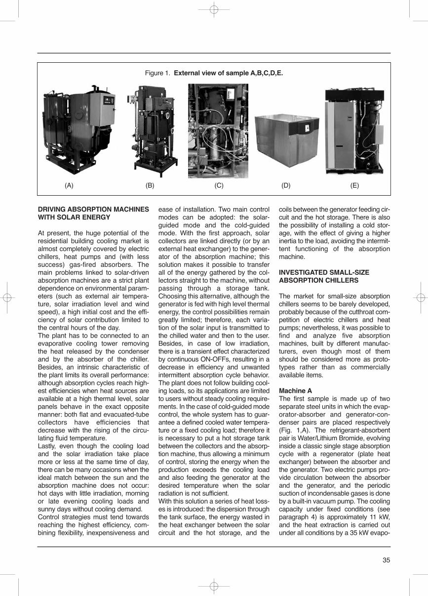
35
DRIVING ABSORPTION MACHINESWITH SOLAR ENERGY
At present, the huge potential of theresidential building cooling market isalmost completely covered by electricchillers, heat pumps and (with lesssuccess) gas-fired absorbers. Themain problems linked to solar-drivenabsorption machines are a strict plantdependence on environmental param-eters (such as external air tempera-ture, solar irradiation level and windspeed), a high initial cost and the effi-ciency of solar contribution limited tothe central hours of the day.The plant has to be connected to anevaporative cooling tower removingthe heat released by the condenserand by the absorber of the chiller.Besides, an intrinsic characteristic ofthe plant limits its overall performance:although absorption cycles reach high-est efficiencies when heat sources areavailable at a high thermal level, solarpanels behave in the exact oppositemanner: both flat and evacuated-tubecollectors have efficiencies thatdecrease with the rising of the circu-lating fluid temperature.Lastly, even though the cooling loadand the solar irradiation take placemore or less at the same time of day,there can be many occasions when theideal match between the sun and theabsorption machine does not occur:hot days with little irradiation, morningor late evening cooling loads andsunny days without cooling demand. Control strategies must tend towardsreaching the highest efficiency, com-bining flexibility, inexpensiveness and
ease of installation. Two main controlmodes can be adopted: the solar-guided mode and the cold-guidedmode. With the first approach, solarcollectors are linked directly (or by anexternal heat exchanger) to the gener-ator of the absorption machine; thissolution makes it possible to transferall of the energy gathered by the col-lectors straight to the machine, withoutpassing through a storage tank.Choosing this alternative, although thegenerator is fed with high level thermalenergy, the control possibilities remaingreatly limited; therefore, each varia-tion of the solar input is transmitted tothe chilled water and then to the user.Besides, in case of low irradiation,there is a transient effect characterizedby continuous ON-OFFs, resulting in adecrease in efficiency and unwantedintermittent absorption cycle behavior.The plant does not follow building cool-ing loads, so its applications are limitedto users without steady cooling require-ments. In the case of cold-guided modecontrol, the whole system has to guar-antee a defined cooled water tempera-ture or a fixed cooling load; therefore itis necessary to put a hot storage tankbetween the collectors and the absorp-tion machine, thus allowing a minimumof control, storing the energy when theproduction exceeds the cooling loadand also feeding the generator at thedesired temperature when the solarradiation is not sufficient.With this solution a series of heat loss-es is introduced: the dispersion throughthe tank surface, the energy wasted inthe heat exchanger between the solarcircuit and the hot storage, and the
coils between the generator feeding cir-cuit and the hot storage. There is alsothe possibility of installing a cold stor-age, with the effect of giving a higherinertia to the load, avoiding the intermit-tent functioning of the absorptionmachine.
INVESTIGATED SMALL-SIZEABSORPTION CHILLERS
The market for small-size absorptionchillers seems to be barely developed,probably because of the cutthroat com-petition of electric chillers and heatpumps; nevertheless, it was possible tofind and analyze five absorptionmachines, built by different manufac-turers, even though most of themshould be considered more as proto-types rather than as commerciallyavailable items.
Machine AThe first sample is made up of twoseparate steel units in which the evap-orator-absorber and generator-con-denser pairs are placed respectively(Fig. 1,A). The refrigerant-absorbentpair is Water/Lithium Bromide, evolvinginside a classic single stage absorptioncycle with a regenerator (plate heatexchanger) between the absorber andthe generator. Two electric pumps pro-vide circulation between the absorberand the generator, and the periodicsuction of incondensable gases is doneby a built-in vacuum pump. The coolingcapacity under fixed conditions (seeparagraph 4) is approximately 11 kW,and the heat extraction is carried outunder all conditions by a 35 kW evapo-
Figure 1. External view of sample A,B,C,D,E.
(A) (B) (C) (D) (E)
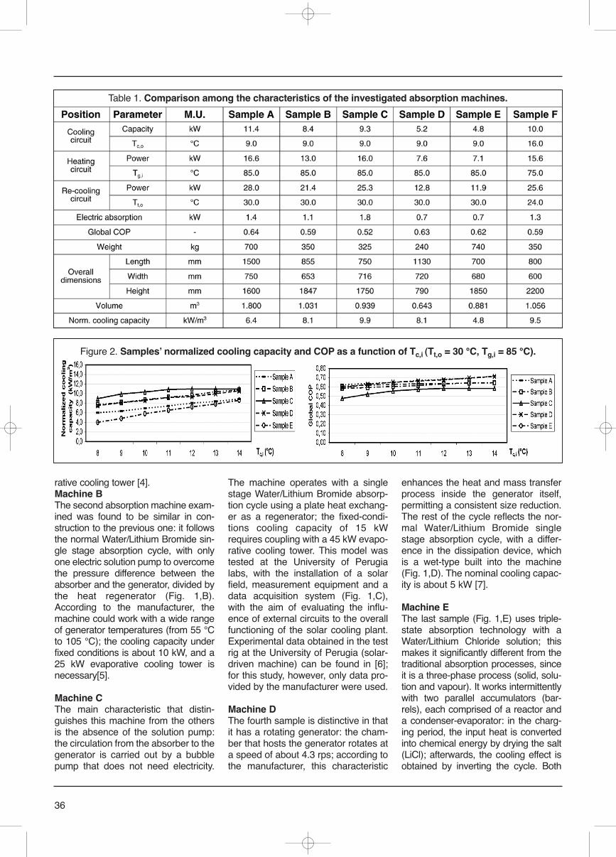
36
rative cooling tower [4].Machine BThe second absorption machine exam-ined was found to be similar in con-struction to the previous one: it followsthe normal Water/Lithium Bromide sin-gle stage absorption cycle, with onlyone electric solution pump to overcomethe pressure difference between theabsorber and the generator, divided bythe heat regenerator (Fig. 1,B).According to the manufacturer, themachine could work with a wide rangeof generator temperatures (from 55 °Cto 105 °C); the cooling capacity underfixed conditions is about 10 kW, and a25 kW evaporative cooling tower isnecessary[5].
Machine CThe main characteristic that distin-guishes this machine from the othersis the absence of the solution pump:the circulation from the absorber to thegenerator is carried out by a bubblepump that does not need electricity.
The machine operates with a singlestage Water/Lithium Bromide absorp-tion cycle using a plate heat exchang-er as a regenerator; the fixed-condi-tions cooling capacity of 15 kWrequires coupling with a 45 kW evapo-rative cooling tower. This model wastested at the University of Perugialabs, with the installation of a solarfield, measurement equipment and adata acquisition system (Fig. 1,C),with the aim of evaluating the influ-ence of external circuits to the overallfunctioning of the solar cooling plant.Experimental data obtained in the testrig at the University of Perugia (solar-driven machine) can be found in [6];for this study, however, only data pro-vided by the manufacturer were used.
Machine DThe fourth sample is distinctive in thatit has a rotating generator: the cham-ber that hosts the generator rotates ata speed of about 4.3 rps; according tothe manufacturer, this characteristic
enhances the heat and mass transferprocess inside the generator itself,permitting a consistent size reduction.The rest of the cycle reflects the nor-mal Water/Lithium Bromide singlestage absorption cycle, with a differ-ence in the dissipation device, whichis a wet-type built into the machine(Fig. 1,D). The nominal cooling capac-ity is about 5 kW [7].
Machine EThe last sample (Fig. 1,E) uses triple-state absorption technology with aWater/Lithium Chloride solution; thismakes it significantly different from thetraditional absorption processes, sinceit is a three-phase process (solid, solu-tion and vapour). It works intermittentlywith two parallel accumulators (bar-rels), each comprised of a reactor anda condenser-evaporator: in the charg-ing period, the input heat is convertedinto chemical energy by drying the salt(LiCl); afterwards, the cooling effect isobtained by inverting the cycle. Both
Table 1. Comparison among the characteristics of the investigated absorption machines.
Figure 2. Samples ̓normalized cooling capacity and COP as a function of Tc,i (Tt,o = 30 °C, Tg,i = 85 °C).
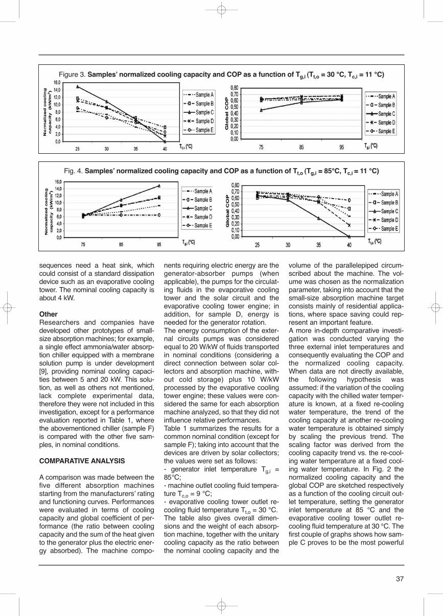
sequences need a heat sink, whichcould consist of a standard dissipationdevice such as an evaporative coolingtower. The nominal cooling capacity isabout 4 kW.
OtherResearchers and companies havedeveloped other prototypes of small-size absorption machines; for example,a single effect ammonia/water absorp-tion chiller equipped with a membranesolution pump is under development[9], providing nominal cooling capaci-ties between 5 and 20 kW. This solu-tion, as well as others not mentioned,lack complete experimental data,therefore they were not included in thisinvestigation, except for a performanceevaluation reported in Table 1, wherethe abovementioned chiller (sample F)is compared with the other five sam-ples, in nominal conditions.
COMPARATIVE ANALYSIS
A comparison was made between thefive different absorption machinesstarting from the manufacturers ̓ratingand functioning curves. Performanceswere evaluated in terms of coolingcapacity and global coefficient of per-formance (the ratio between coolingcapacity and the sum of the heat givento the generator plus the electric ener-gy absorbed). The machine compo-
nents requiring electric energy are thegenerator-absorber pumps (whenapplicable), the pumps for the circulat-ing fluids in the evaporative coolingtower and the solar circuit and theevaporative cooling tower engine; inaddition, for sample D, energy isneeded for the generator rotation. The energy consumption of the exter-nal circuits pumps was consideredequal to 20 W/kW of fluids transportedin nominal conditions (considering adirect connection between solar col-lectors and absorption machine, with-out cold storage) plus 10 W/kWprocessed by the evaporative coolingtower engine; these values were con-sidered the same for each absorptionmachine analyzed, so that they did notinfluence relative performances. Table 1 summarizes the results for acommon nominal condition (except forsample F); taking into account that thedevices are driven by solar collectors;the values were set as follows: - generator inlet temperature Tg,i =85°C;- machine outlet cooling fluid tempera-ture Tc,o = 9 °C;- evaporative cooling tower outlet re-cooling fluid temperature Tt,o = 30 °C.The table also gives overall dimen-sions and the weight of each absorp-tion machine, together with the unitarycooling capacity as the ratio betweenthe nominal cooling capacity and the
volume of the parallelepiped circum-scribed about the machine. The vol-ume was chosen as the normalizationparameter, taking into account that thesmall-size absorption machine targetconsists mainly of residential applica-tions, where space saving could rep-resent an important feature.A more in-depth comparative investi-gation was conducted varying thethree external inlet temperatures andconsequently evaluating the COP andthe normalized cooling capacity.When data are not directly available,the following hypothesis wasassumed: if the variation of the coolingcapacity with the chilled water temper-ature is known, at a fixed re-coolingwater temperature, the trend of thecooling capacity at another re-coolingwater temperature is obtained simplyby scaling the previous trend. Thescaling factor was derived from thecooling capacity trend vs. the re-cool-ing water temperature at a fixed cool-ing water temperature. In Fig. 2 thenormalized cooling capacity and theglobal COP are sketched respectivelyas a function of the cooling circuit out-let temperature, setting the generatorinlet temperature at 85 °C and theevaporative cooling tower outlet re-cooling fluid temperature at 30 °C. Thefirst couple of graphs shows how sam-ple C proves to be the most powerful
37
Fig. 4. Samples ̓normalized cooling capacity and COP as a function of Tt,o (Tg,i = 85°C, Tc,i = 11 °C)
Figure 3. Samples ̓normalized cooling capacity and COP as a function of Tg,i (Tt,o = 30 °C, Tc,i = 11 °C)
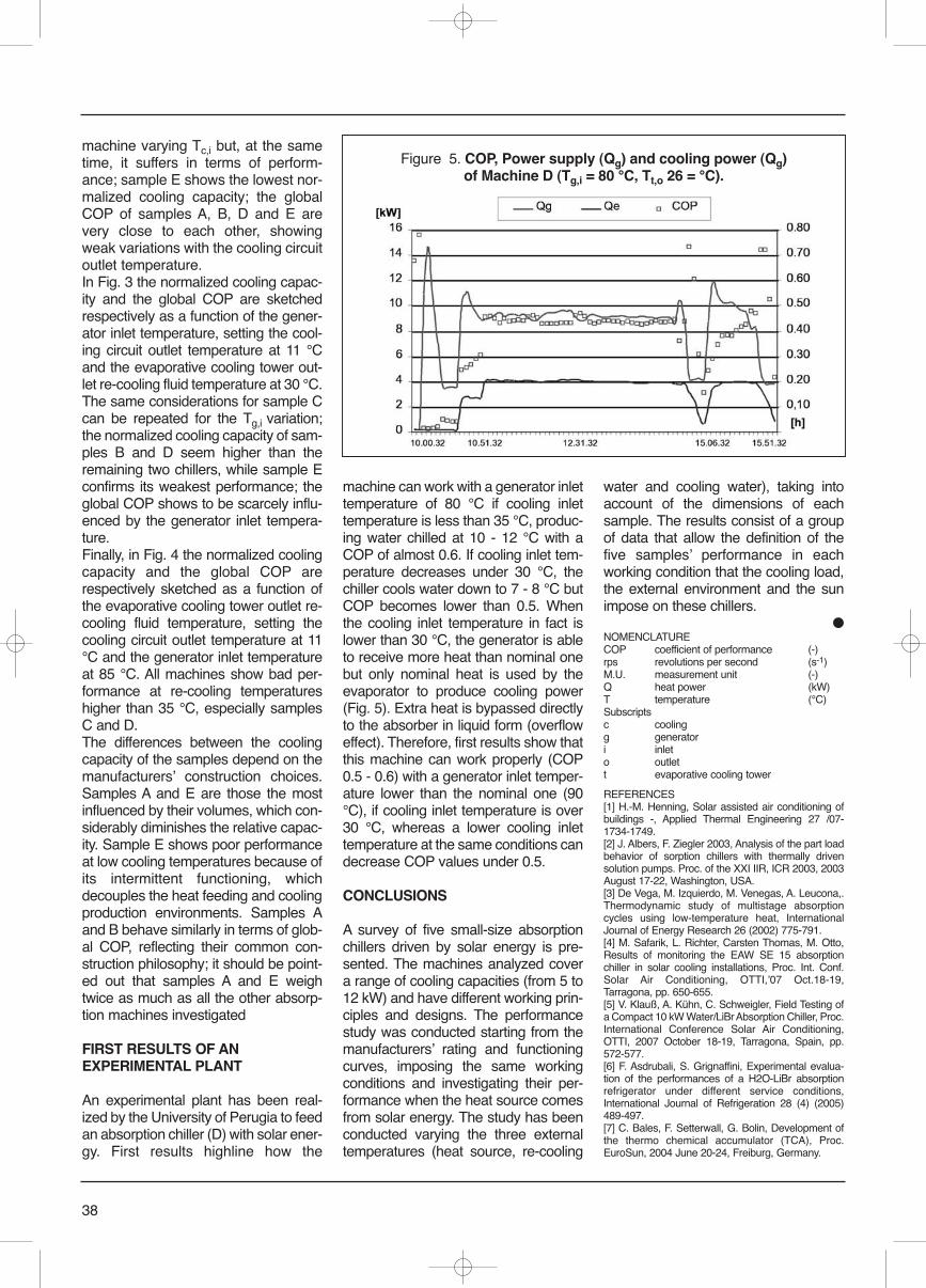
38
machine varying Tc,i but, at the sametime, it suffers in terms of perform-ance; sample E shows the lowest nor-malized cooling capacity; the globalCOP of samples A, B, D and E arevery close to each other, showingweak variations with the cooling circuitoutlet temperature.In Fig. 3 the normalized cooling capac-ity and the global COP are sketchedrespectively as a function of the gener-ator inlet temperature, setting the cool-ing circuit outlet temperature at 11 °Cand the evaporative cooling tower out-let re-cooling fluid temperature at 30 °C.The same considerations for sample Ccan be repeated for the Tg,i variation;the normalized cooling capacity of sam-ples B and D seem higher than theremaining two chillers, while sample Econfirms its weakest performance; theglobal COP shows to be scarcely influ-enced by the generator inlet tempera-ture.Finally, in Fig. 4 the normalized coolingcapacity and the global COP arerespectively sketched as a function ofthe evaporative cooling tower outlet re-cooling fluid temperature, setting thecooling circuit outlet temperature at 11°C and the generator inlet temperatureat 85 °C. All machines show bad per-formance at re-cooling temperatureshigher than 35 °C, especially samplesC and D.The differences between the coolingcapacity of the samples depend on themanufacturers ̓ construction choices.Samples A and E are those the mostinfluenced by their volumes, which con-siderably diminishes the relative capac-ity. Sample E shows poor performanceat low cooling temperatures because ofits intermittent functioning, whichdecouples the heat feeding and coolingproduction environments. Samples Aand B behave similarly in terms of glob-al COP, reflecting their common con-struction philosophy; it should be point-ed out that samples A and E weightwice as much as all the other absorp-tion machines investigated
FIRST RESULTS OF ANEXPERIMENTAL PLANT
An experimental plant has been real-ized by the University of Perugia to feedan absorption chiller (D) with solar ener-gy. First results highline how the
machine can work with a generator inlettemperature of 80 °C if cooling inlettemperature is less than 35 °C, produc-ing water chilled at 10 - 12 °C with aCOP of almost 0.6. If cooling inlet tem-perature decreases under 30 °C, thechiller cools water down to 7 - 8 °C butCOP becomes lower than 0.5. Whenthe cooling inlet temperature in fact islower than 30 °C, the generator is ableto receive more heat than nominal onebut only nominal heat is used by theevaporator to produce cooling power(Fig. 5). Extra heat is bypassed directlyto the absorber in liquid form (overfloweffect). Therefore, first results show thatthis machine can work properly (COP0.5 - 0.6) with a generator inlet temper-ature lower than the nominal one (90°C), if cooling inlet temperature is over30 °C, whereas a lower cooling inlettemperature at the same conditions candecrease COP values under 0.5.
CONCLUSIONS
A survey of five small-size absorptionchillers driven by solar energy is pre-sented. The machines analyzed covera range of cooling capacities (from 5 to12 kW) and have different working prin-ciples and designs. The performancestudy was conducted starting from themanufacturers ̓ rating and functioningcurves, imposing the same workingconditions and investigating their per-formance when the heat source comesfrom solar energy. The study has beenconducted varying the three externaltemperatures (heat source, re-cooling
water and cooling water), taking intoaccount of the dimensions of eachsample. The results consist of a groupof data that allow the definition of thefive samples ̓ performance in eachworking condition that the cooling load,the external environment and the sunimpose on these chillers.
●NOMENCLATURECOP coefficient of performance (-)rps revolutions per second (s-1)M.U. measurement unit (-)Q heat power (kW)T temperature (°C)Subscriptsc coolingg generator i inleto outlett evaporative cooling tower
REFERENCES[1] H.-M. Henning, Solar assisted air conditioning ofbuildings -, Applied Thermal Engineering 27 /07-1734-1749.[2] J. Albers, F. Ziegler 2003, Analysis of the part loadbehavior of sorption chillers with thermally drivensolution pumps. Proc. of the XXI IIR, ICR 2003, 2003August 17-22, Washington, USA.[3] De Vega, M. Izquierdo, M. Venegas, A. Leucona,.Thermodynamic study of multistage absorptioncycles using low-temperature heat, InternationalJournal of Energy Research 26 (2002) 775-791.[4] M. Safarik, L. Richter, Carsten Thomas, M. Otto,Results of monitoring the EAW SE 15 absorptionchiller in solar cooling installations, Proc. Int. Conf.Solar Air Conditioning, OTTI,ʼ07 Oct.18-19,Tarragona, pp. 650-655.[5] V. Klauß, A. Kühn, C. Schweigler, Field Testing ofa Compact 10 kW Water/LiBr Absorption Chiller, Proc.International Conference Solar Air Conditioning,OTTI, 2007 October 18-19, Tarragona, Spain, pp.572-577.[6] F. Asdrubali, S. Grignaffini, Experimental evalua-tion of the performances of a H2O-LiBr absorptionrefrigerator under different service conditions,International Journal of Refrigeration 28 (4) (2005)489-497.[7] C. Bales, F. Setterwall, G. Bolin, Development ofthe thermo chemical accumulator (TCA), Proc.EuroSun, 2004 June 20-24, Freiburg, Germany.
Figure 5. COP, Power supply (Qg) and cooling power (Qg)of Machine D (Tg,i = 80 °C, Tt,o 26 = °C).
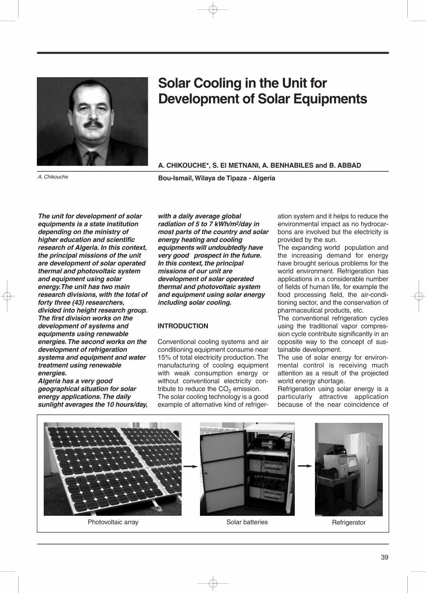
The unit for development of solarequipments is a state institutiondepending on the ministry ofhigher education and scientificresearch of Algeria. In this context,the principal missions of the unitare development of solar operatedthermal and photovoltaic systemand equipment using solarenergy.The unit has two mainresearch divisions, with the total offorty three (43) researchers,divided into height research group.The first division works on thedevelopment of systems andequipments using renewableenergies. The second works on thedevelopment of refrigerationsystems and equipment and watertreatment using renewableenergies. Algeria has a very goodgeographical situation for solarenergy applications. The dailysunlight averages the 10 hours/day,
with a daily average globalradiation of 5 to 7 kWh/m2/day inmost parts of the country and solarenergy heating and coolingequipments will undoubtedly havevery good prospect in the future.In this context, the principalmissions of our unit aredevelopment of solar operatedthermal and photovoltaic systemand equipment using solar energyincluding solar cooling.
INTRODUCTION
Conventional cooling systems and airconditioning equipment consume near15% of total electricity production. Themanufacturing of cooling equipmentwith weak consumption energy orwithout conventional electricity con-tribute to reduce the CO2 emission.The solar cooling technology is a goodexample of alternative kind of refriger-
ation system and it helps to reduce theenvironmental impact as no hydrocar-bons are involved but the electricity isprovided by the sun. The expanding world population andthe increasing demand for energyhave brought serious problems for theworld environment. Refrigeration hasapplications in a considerable numberof fields of human life, for example thefood processing field, the air-condi-tioning sector, and the conservation ofpharmaceutical products, etc.The conventional refrigeration cyclesusing the traditional vapor compres-sion cycle contribute significantly in anopposite way to the concept of sus-tainable development.The use of solar energy for environ-mental control is receiving muchattention as a result of the projectedworld energy shortage.Refrigeration using solar energy is aparticularly attractive applicationbecause of the near coincidence of
39
Solar Cooling in the Unit forDevelopment of Solar Equipments
A. CHIKOUCHE*, S. El METNANI, A. BENHABILES and B. ABBAD
Bou-Ismail, Wilaya de Tipaza - Algeria
Photovoltaic array Solar batteries Refrigerator
A. Chikouche
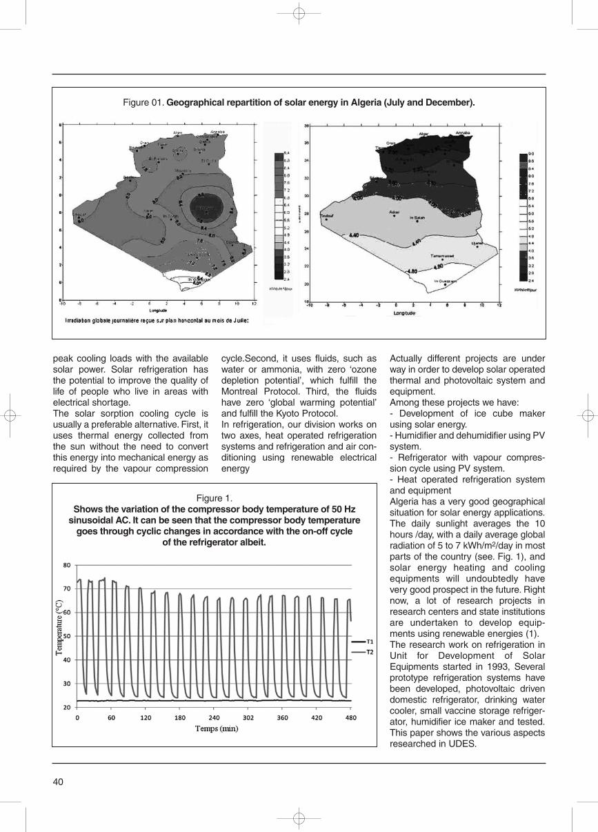
peak cooling loads with the availablesolar power. Solar refrigeration hasthe potential to improve the quality oflife of people who live in areas withelectrical shortage.The solar sorption cooling cycle isusually a preferable alternative. First, ituses thermal energy collected fromthe sun without the need to convertthis energy into mechanical energy asrequired by the vapour compression
cycle.Second, it uses fluids, such aswater or ammonia, with zero ‘ozonedepletion potential’, which fulfill theMontreal Protocol. Third, the fluidshave zero ‘global warming potential’and fulfill the Kyoto Protocol.In refrigeration, our division works ontwo axes, heat operated refrigerationsystems and refrigeration and air con-ditioning using renewable electricalenergy
Actually different projects are underway in order to develop solar operatedthermal and photovoltaic system andequipment.Among these projects we have:- Development of ice cube makerusing solar energy.- Humidifier and dehumidifier using PVsystem.- Refrigerator with vapour compres-sion cycle using PV system.- Heat operated refrigeration systemand equipmentAlgeria has a very good geographicalsituation for solar energy applications.The daily sunlight averages the 10hours /day, with a daily average globalradiation of 5 to 7 kWh/m2/day in mostparts of the country (see. Fig. 1), andsolar energy heating and coolingequipments will undoubtedly havevery good prospect in the future. Rightnow, a lot of research projects inresearch centers and state institutionsare undertaken to develop equip-ments using renewable energies (1).The research work on refrigeration inUnit for Development of SolarEquipments started in 1993, Severalprototype refrigeration systems havebeen developed, photovoltaic drivendomestic refrigerator, drinking watercooler, small vaccine storage refriger-ator, humidifier ice maker and tested.This paper shows the various aspectsresearched in UDES.
40
Figure 01. Geographical repartition of solar energy in Algeria (July and December).
Figure 1.Shows the variation of the compressor body temperature of 50 Hz
sinusoidal AC. It can be seen that the compressor body temperaturegoes through cyclic changes in accordance with the on-off cycle
of the refrigerator albeit.
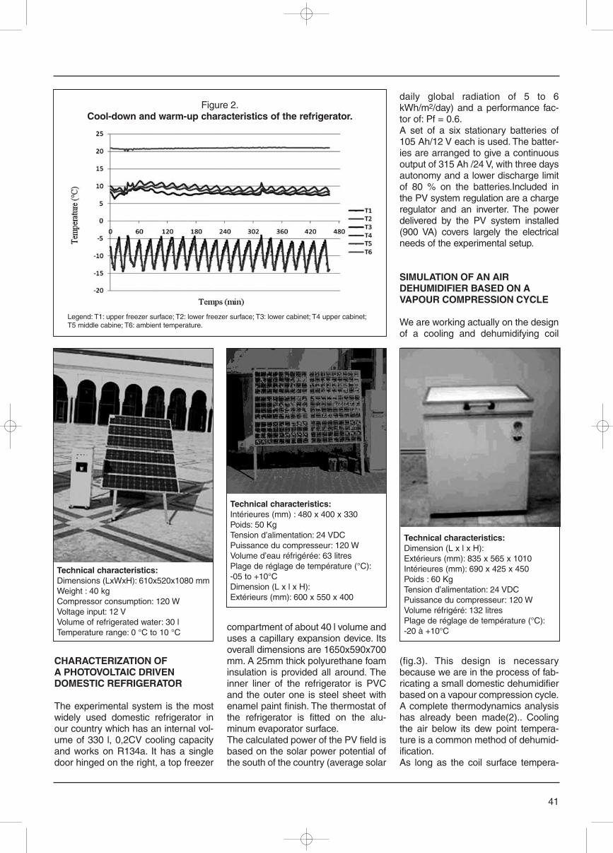
CHARACTERIZATION OFA PHOTOVOLTAIC DRIVENDOMESTIC REFRIGERATOR
The experimental system is the mostwidely used domestic refrigerator inour country which has an internal vol-ume of 330 l, 0,2CV cooling capacityand works on R134a. It has a singledoor hinged on the right, a top freezer
compartment of about 40 l volume anduses a capillary expansion device. Itsoverall dimensions are 1650x590x700mm. A 25mm thick polyurethane foaminsulation is provided all around. Theinner liner of the refrigerator is PVCand the outer one is steel sheet withenamel paint finish. The thermostat ofthe refrigerator is fitted on the alu-minum evaporator surface. The calculated power of the PV field isbased on the solar power potential ofthe south of the country (average solar
daily global radiation of 5 to 6kWh/m2/day) and a performance fac-tor of: Pf = 0.6.A set of a six stationary batteries of105 Ah/12 V each is used. The batter-ies are arranged to give a continuousoutput of 315 Ah /24 V, with three daysautonomy and a lower discharge limitof 80 % on the batteries.Included inthe PV system regulation are a chargeregulator and an inverter. The powerdelivered by the PV system installed(900 VA) covers largely the electricalneeds of the experimental setup.
SIMULATION OF AN AIRDEHUMIDIFIER BASED ON AVAPOUR COMPRESSION CYCLE
We are working actually on the designof a cooling and dehumidifying coil
(fig.3). This design is necessarybecause we are in the process of fab-ricating a small domestic dehumidifierbased on a vapour compression cycle.A complete thermodynamics analysishas already been made(2).. Coolingthe air below its dew point tempera-ture is a common method of dehumid-ification. As long as the coil surface tempera-
41
Figure 2.Cool-down and warm-up characteristics of the refrigerator.
Legend: T1: upper freezer surface; T2: lower freezer surface; T3: lower cabinet; T4 upper cabinet;T5 middle cabine; T6: ambient temperature.
Technical characteristics:Dimensions (LxWxH): 610x520x1080 mmWeight : 40 kgCompressor consumption: 120 WVoltage input: 12 VVolume of refrigerated water: 30 lTemperature range: 0 °C to 10 °C
Technical characteristics:Intérieures (mm) : 480 x 400 x 330Poids: 50 KgTension d’alimentation: 24 VDCPuissance du compresseur: 120 WVolume d’eau réfrigérée: 63 litresPlage de réglage de température (°C):-05 to +10°CDimension (L x l x H): Extérieurs (mm): 600 x 550 x 400
Technical characteristics:Dimension (L x l x H):Extérieurs (mm): 835 x 565 x 1010Intérieures (mm): 690 x 425 x 450Poids : 60 KgTension d’alimentation: 24 VDCPuissance du compresseur: 120 WVolume réfrigéré: 132 litresPlage de réglage de température (°C):-20 à +10°C
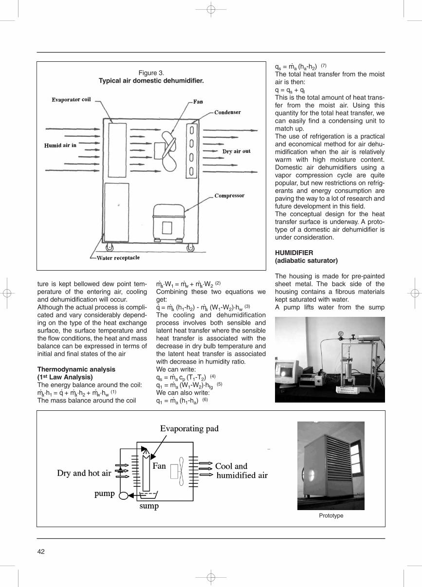
ture is kept bellowed dew point tem-perature of the entering air, coolingand dehumidification will occur. Although the actual process is compli-cated and vary considerably depend-ing on the type of the heat exchangesurface, the surface temperature andthe flow conditions, the heat and massbalance can be expressed in terms ofinitial and final states of the air
Thermodynamic analysis(1st Law Analysis) The energy balance around the coil:m·a·h1 = q· + m·a·h2 + m·w·hw
(1)
The mass balance around the coil
m·a·W1 = m·w + m·a·W2(2)
Combining these two equations weget:q· = m·a (h1-h2) - m
·a (W1-W2)·hw
(3)
The cooling and dehumidificationprocess involves both sensible andlatent heat transfer where the sensibleheat transfer is associated with thedecrease in dry bulb temperature andthe latent heat transfer is associatedwith decrease in humidity ratio.We can write:qs = m· a cp (T1-T2) (4)
q1 = m· a (W1-W2)·hfg(5)
We can also write:q1 = m· a (h1-ha) (6)
qs = m· a (ha-h2) (7)
The total heat transfer from the moistair is then:q = qs + qlThis is the total amount of heat trans-fer from the moist air. Using thisquantity for the total heat transfer, wecan easily find a condensing unit tomatch up.The use of refrigeration is a practicaland economical method for air dehu-midification when the air is relativelywarm with high moisture content.Domestic air dehumidifiers using avapor compression cycle are quitepopular, but new restrictions on refrig-erants and energy consumption arepaving the way to a lot of research andfuture development in this field. The conceptual design for the heattransfer surface is underway. A proto-type of a domestic air dehumidifier isunder consideration.
HUMIDIFIER(adiabatic saturator)
The housing is made for pre-paintedsheet metal. The back side of thehousing contains a fibrous materialskept saturated with water.A pump lifts water from the sump
42
Figure 3.Typical air domestic dehumidifier.
Prototype
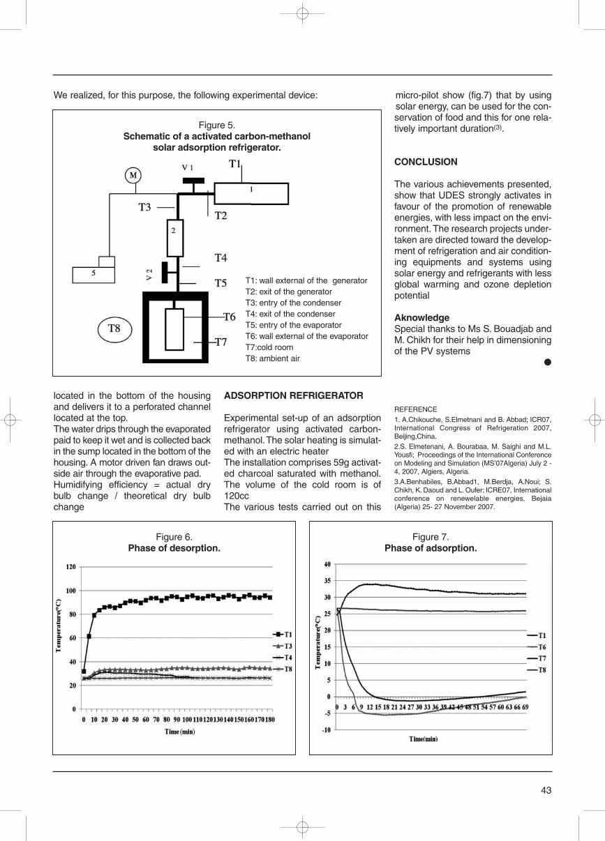
located in the bottom of the housingand delivers it to a perforated channellocated at the top.The water drips through the evaporatedpaid to keep it wet and is collected backin the sump located in the bottom of thehousing. A motor driven fan draws out-side air through the evaporative pad.Humidifying efficiency = actual drybulb change / theoretical dry bulbchange
ADSORPTION REFRIGERATOR
Experimental set-up of an adsorptionrefrigerator using activated carbon-methanol. The solar heating is simulat-ed with an electric heater The installation comprises 59g activat-ed charcoal saturated with methanol.The volume of the cold room is of120ccThe various tests carried out on this
micro-pilot show (fig.7) that by usingsolar energy, can be used for the con-servation of food and this for one rela-tively important duration(3).
CONCLUSION
The various achievements presented,show that UDES strongly activates infavour of the promotion of renewableenergies, with less impact on the envi-ronment. The research projects under-taken are directed toward the develop-ment of refrigeration and air condition-ing equipments and systems usingsolar energy and refrigerants with lessglobal warming and ozone depletionpotential
AknowledgeSpecial thanks to Ms S. Bouadjab andM. Chikh for their help in dimensioningof the PV systems
●
REFERENCE
1. A.Chikouche, S.Elmetnani and B. Abbad; ICR07,International Congress of Refrigeration 2007,Beijing,China.
2.S. Elmetenani, A. Bourabaa, M. Saighi and M.L.Yousfi; Proceedings of the International Conferenceon Modeling and Simulation (MS’07Algeria) July 2 -4, 2007, Algiers, Algeria.
3.A.Benhabiles, B.Abbad1, M.Berdja, A.Noui; S.Chikh, K. Daoud and L. Oufer; ICRE07, Internationalconference on renewelable energies, Bejaia(Algeria) 25- 27 November 2007.
43
Figure 6.Phase of desorption.
Figure 7.Phase of adsorption.
Figure 5.Schematic of a activated carbon-methanol
solar adsorption refrigerator.
T1: wall external of the generatorT2: exit of the generatorT3: entry of the condenserT4: exit of the condenserT5: entry of the evaporatorT6: wall external of the evaporatorT7:cold roomT8: ambient air
We realized, for this purpose, the following experimental device:
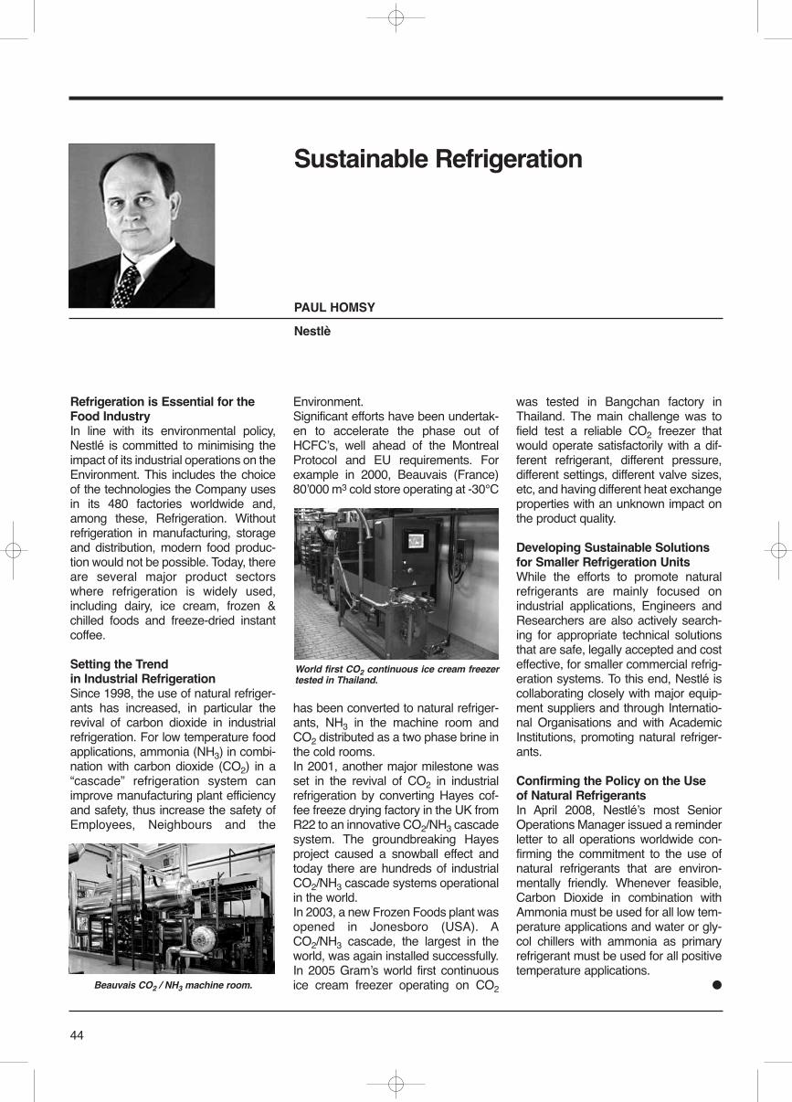
Refrigeration is Essential for theFood IndustryIn line with its environmental policy,Nestlé is committed to minimising theimpact of its industrial operations on theEnvironment. This includes the choiceof the technologies the Company usesin its 480 factories worldwide and,among these, Refrigeration. Withoutrefrigeration in manufacturing, storageand distribution, modern food produc-tion would not be possible. Today, thereare several major product sectorswhere refrigeration is widely used,including dairy, ice cream, frozen &chilled foods and freeze-dried instantcoffee.
Setting the Trendin Industrial RefrigerationSince 1998, the use of natural refriger-ants has increased, in particular therevival of carbon dioxide in industrialrefrigeration. For low temperature foodapplications, ammonia (NH3) in combi-nation with carbon dioxide (CO2) in a“cascade” refrigeration system canimprove manufacturing plant efficiencyand safety, thus increase the safety ofEmployees, Neighbours and the
Environment. Significant efforts have been undertak-en to accelerate the phase out ofHCFCʼs, well ahead of the MontrealProtocol and EU requirements. Forexample in 2000, Beauvais (France)80ʼ000 m3 cold store operating at -30°C
has been converted to natural refriger-ants, NH3 in the machine room andCO2 distributed as a two phase brine inthe cold rooms. In 2001, another major milestone wasset in the revival of CO2 in industrialrefrigeration by converting Hayes cof-fee freeze drying factory in the UK fromR22 to an innovative CO2/NH3 cascadesystem. The groundbreaking Hayesproject caused a snowball effect andtoday there are hundreds of industrialCO2/NH3 cascade systems operationalin the world. In 2003, a new Frozen Foods plant wasopened in Jonesboro (USA). ACO2/NH3 cascade, the largest in theworld, was again installed successfully. In 2005 Gramʼs world first continuousice cream freezer operating on CO2
was tested in Bangchan factory inThailand. The main challenge was tofield test a reliable CO2 freezer thatwould operate satisfactorily with a dif-ferent refrigerant, different pressure,different settings, different valve sizes,etc, and having different heat exchangeproperties with an unknown impact onthe product quality.
Developing Sustainable Solutionsfor Smaller Refrigeration UnitsWhile the efforts to promote naturalrefrigerants are mainly focused onindustrial applications, Engineers andResearchers are also actively search-ing for appropriate technical solutionsthat are safe, legally accepted and costeffective, for smaller commercial refrig-eration systems. To this end, Nestlé iscollaborating closely with major equip-ment suppliers and through Internatio-nal Organisations and with AcademicInstitutions, promoting natural refriger-ants.
Confirming the Policy on the Useof Natural RefrigerantsIn April 2008, Nestléʼs most SeniorOperations Manager issued a reminderletter to all operations worldwide con-firming the commitment to the use ofnatural refrigerants that are environ-mentally friendly. Whenever feasible,Carbon Dioxide in combination withAmmonia must be used for all low tem-perature applications and water or gly-col chillers with ammonia as primaryrefrigerant must be used for all positivetemperature applications.
●
44
Sustainable Refrigeration
PAUL HOMSY
Nestlè
Beauvais CO2 / NH3 machine room.
World first CO2 continuous ice cream freezertested in Thailand.
Magnetic refrigeration is an adiabaticcooling method which applies themagnetocaloric effect (MCE). Fromthe point of view of basic physics, itshows an analogy to the conventionalgas compression/expansion method.It has been applied for many years incryogenics, to reach very low temper-atures. In 1976, Brown presented thefirst room temperature refrigeratorapplying adiabatic magnetization anddemagnetization.1 After the discoveryof the “giant” magnetocaloric effect(GMCE) in Gd5(Si2Ge2) in 1997 byGschneidner and Pecharsky,2 whichincreases the MCE, many scientistsand industrial representatives of therefrigeration community concede thatthis “new” technology (applying per-manent magnets and the GMCE) hasa good future potential for a remark-able penetration into the refrigerationmarket. They are convinced that inseveral different market domains, con-ventional refrigeration could bereplaced by magnetic refrigeration.The main reason for such an attitudeis the possibility to replace the HFCrefrigerants by environmentally benignmagnetocaloric alloys. HFCs, with atypical global warming potential(GWP) of 1000 to 3000 times that ofCO2, at present show an increasingsales market, which has its cause inthe phasing out of the more destruc-tive HCFCs and CFCs. This phasingout process is still ongoing and inmost developing countries HCFCsand CFCs are still allowed. Systemswith natural refrigerants (ammonia,CO2, propane, etc.) are good solu-
tions for numerous applications, but todate, none of them have reached aremarkable breakthrough on a widescale of applications in refrigeration.Other advantages include the highercycle efficiencies of magnetic refriger-ation processes compared with thoseof gas-compression refrigeration andthe noiseless operating conditions of amagnetic refrigerator. This IIR infor-matory note briefly highlights thestate-of-the-art, the advantages anddisadvantages of this promising tech-nology.
INTRODUCTION
The refrigeration-technology market isclosely related to beverage and foodproduction, industrial process, thechemical and pharmaceutical industry,the automotive sector, etc. Some ofthese sectors have strongly growingmarkets, thanks to the rising incomesof Eastern European, Indian andChinese customers, with their desirefor modern consumer goods drivingsuch development. The retail market,supermarket and hypermarket chainsare strongly benefiting from this devel-opment. Because the number of builtalternative refrigeration technologiessuch as absorption or adsorptionrefrigeration, thermoelectric and ther-moacoustic refrigeration, etc. is negli-gible, this leads to positive prospectsfor the gas-compression system pro-ducers.Furthermore, the tendency to cooldomestic buildings in southern areas
45
Magnetic Refrigerationat Room Temperature
PETER EGOLF RONALD ROSENSWEIG
University of Applied Sciencesof Western Switzerland
Chaires Internationalesde Recherche Blaise Pascal
The University of Engineering andEconomy of the Swiss County ofVaud offers in Yverdon-les-bains(French part of Switzerland) eightdirections of University educationsin the domain of Engineering andthe Economy of Enterprises. With1500 students it is the largestentity of the Haute EcoleSpécialisée de Suisse Occidentale(Hesso). In all its divisionsprofessors with their staff areperforming high quality researchand development for the (local)industry, but also on aninternational level, numerous ofthem with good recognition. Prof.Peter W. Egolf and Prof. OsmannSari are leaders of the Theory andNumerics Division (SIT) and anExperimental Laboratory (TIS) ofthe Thermal Sciences Institute(IGT), respectively. Dr. AndrejKitanovski is responsible formagnetic heating and refrigerationin the Theory and NumericsDivision of IGT.
20th IIF-IIR Informatory Noteon Refrigerating Technologies
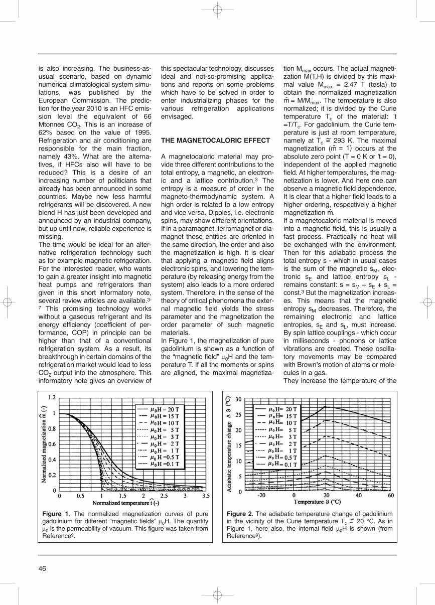
is also increasing. The business-as-usual scenario, based on dynamicnumerical climatological system simu-lations, was published by theEuropean Commission. The predic-tion for the year 2010 is an HFC emis-sion level the equivalent of 66Mtonnes CO2. This is an increase of62% based on the value of 1995.Refrigeration and air conditioning areresponsible for the main fraction,namely 43%. What are the alterna-tives, if HFCs also will have to bereduced? This is a desire of anincreasing number of politicians thatalready has been announced in somecountries. Maybe new less harmfulrefrigerants will be discovered. A newblend H has just been developed andannounced by an industrial company,but up until now, reliable experience ismissing.The time would be ideal for an alter-native refrigeration technology suchas for example magnetic refrigeration.For the interested reader, who wantsto gain a greater insight into magneticheat pumps and refrigerators thangiven in this short informatory note,several review articles are available.3-
7 This promising technology workswithout a gaseous refrigerant and itsenergy efficiency (coefficient of per-formance, COP) in principle can behigher than that of a conventionalrefrigeration system. As a result, itsbreakthrough in certain domains of therefrigeration market would lead to lessCO2 output into the atmosphere. Thisinformatory note gives an overview of
this spectacular technology, discussesideal and not-so-promising applica-tions and reports on some problemswhich have to be solved in order toenter industrializing phases for thevarious refrigeration applicationsenvisaged.
THE MAGNETOCALORIC EFFECT
A magnetocaloric material may pro-vide three different contributions to thetotal entropy, a magnetic, an electron-ic and a lattice contribution.3 Theentropy is a measure of order in themagneto-thermodynamic system. Ahigh order is related to a low entropyand vice versa. Dipoles, i.e. electronicspins, may show different orientations.If in a paramagnet, ferromagnet or dia-magnet these entities are oriented inthe same direction, the order and alsothe magnetization is high. It is clearthat applying a magnetic field alignselectronic spins, and lowering the tem-perature (by releasing energy from thesystem) also leads to a more orderedsystem. Therefore, in the sense of thetheory of critical phenomena the exter-nal magnetic field yields the stressparameter and the magnetization theorder parameter of such magneticmaterials.In Figure 1, the magnetization of puregadolinium is shown as a function ofthe “magnetic field” μ0H and the tem-perature T. If all the moments or spinsare aligned, the maximal magnetiza-
tion Mmax occurs. The actual magneti-zation M(T,H) is divided by this maxi-mal value Mmax = 2.47 T (tesla) toobtain the normalized magnetizationm̂ = M/Mmax. The temperature is alsonormalized; it is divided by the Curietemperature Tc of the material: ʼt=T/Tc. For gadolinium, the Curie tem-perature is just at room temperature,namely at Tc =~ 293 K. The maximalmagnetization (m̂ = 1) occurs at theabsolute zero point (T = 0 K or ʼt = 0),independent of the applied magneticfield. At higher temperatures, the mag-netization is lower. And here one canobserve a magnetic field dependence.It is clear that a higher field leads to ahigher ordering, respectively a highermagnetization m̂.If a magnetocaloric material is movedinto a magnetic field, this is usually afast process. Practically no heat willbe exchanged with the environment.Then for this adiabatic process thetotal entropy s - which in usual casesis the sum of the magnetic sM, elec-tronic sE and lattice entropy sL -remains constant: s = sM + sE + sL =const.3 But the magnetization increas-es. This means that the magneticentropy sM decreases. Therefore, theremaining electronic and latticeentropies, sE and sL, must increase.By spin lattice couplings - which occurin milliseconds - phonons or latticevibrations are created. These oscilla-tory movements may be comparedwith Brownʼs motion of atoms or mole-cules in a gas.They increase the temperature of the
46
Figure 1. The normalized magnetization curves of puregadolinium for different “magnetic fields” μ0H. The quantityμ0 is the permeability of vacuum. This figure was taken fromReference9.
Figure 2. The adiabatic temperature change of gadoliniumin the vicinity of the Curie temperature Tc =~ 20 °C. As inFigure 1, here also, the internal field μ0H is shown (fromReference9).
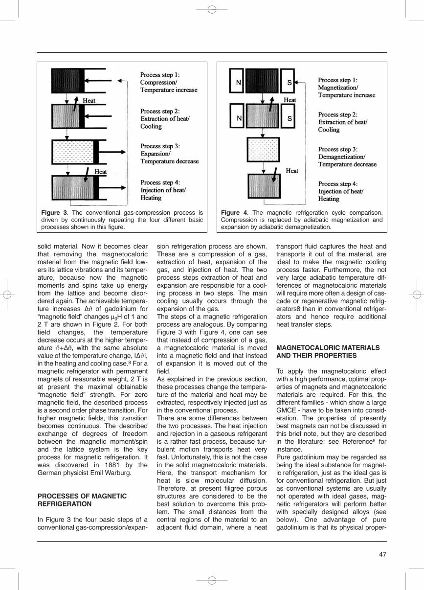
solid material. Now it becomes clearthat removing the magnetocaloricmaterial from the magnetic field low-ers its lattice vibrations and its temper-ature, because now the magneticmoments and spins take up energyfrom the lattice and become disor-dered again. The achievable tempera-ture increases Δϑ of gadolinium for“magnetic field” changes μ0H of 1 and2 T are shown in Figure 2. For bothfield changes, the temperaturedecrease occurs at the higher temper-ature ϑ+Δϑ, with the same absolutevalue of the temperature change, IΔϑI,in the heating and cooling case.8 For amagnetic refrigerator with permanentmagnets of reasonable weight, 2 T isat present the maximal obtainable“magnetic field” strength. For zeromagnetic field, the described processis a second order phase transition. Forhigher magnetic fields, this transitionbecomes continuous. The describedexchange of degrees of freedombetween the magnetic moment/spinand the lattice system is the keyprocess for magnetic refrigeration. Itwas discovered in 1881 by theGerman physicist Emil Warburg.
PROCESSES OF MAGNETICREFRIGERATION
In Figure 3 the four basic steps of aconventional gas-compression/expan-
sion refrigeration process are shown.These are a compression of a gas,extraction of heat, expansion of thegas, and injection of heat. The twoprocess steps extraction of heat andexpansion are responsible for a cool-ing process in two steps. The maincooling usually occurs through theexpansion of the gas.The steps of a magnetic refrigerationprocess are analogous. By comparingFigure 3 with Figure 4, one can seethat instead of compression of a gas,a magnetocaloric material is movedinto a magnetic field and that insteadof expansion it is moved out of thefield.As explained in the previous section,these processes change the tempera-ture of the material and heat may beextracted, respectively injected just asin the conventional process.There are some differences betweenthe two processes. The heat injectionand rejection in a gaseous refrigerantis a rather fast process, because tur-bulent motion transports heat veryfast. Unfortunately, this is not the casein the solid magnetocaloric materials.Here, the transport mechanism forheat is slow molecular diffusion.Therefore, at present filigree porousstructures are considered to be thebest solution to overcome this prob-lem. The small distances from thecentral regions of the material to anadjacent fluid domain, where a heat
transport fluid captures the heat andtransports it out of the material, areideal to make the magnetic coolingprocess faster. Furthermore, the notvery large adiabatic temperature dif-ferences of magnetocaloric materialswill require more often a design of cas-cade or regenerative magnetic refrig-erators8 than in conventional refriger-ators and hence require additionalheat transfer steps.
MAGNETOCALORIC MATERIALSAND THEIR PROPERTIES
To apply the magnetocaloric effectwith a high performance, optimal prop-erties of magnets and magnetocaloricmaterials are required. For this, thedifferent families - which show a largeGMCE - have to be taken into consid-eration. The properties of presentlybest magnets can not be discussed inthis brief note, but they are describedin the literature: see Reference6 forinstance.Pure gadolinium may be regarded asbeing the ideal substance for magnet-ic refrigeration, just as the ideal gas isfor conventional refrigeration. But justas conventional systems are usuallynot operated with ideal gases, mag-netic refrigerators will perform betterwith specially designed alloys (seebelow). One advantage of puregadolinium is that its physical proper-
47
Figure 3. The conventional gas-compression process isdriven by continuously repeating the four different basicprocesses shown in this figure.
Figure 4. The magnetic refrigeration cycle comparison.Compression is replaced by adiabatic magnetization andexpansion by adiabatic demagnetization.
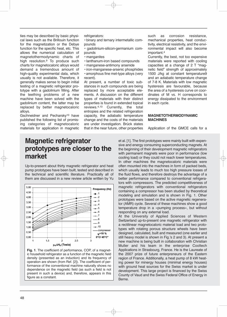
ties may be described by basic physi-cal laws such as the Brillouin functionfor the magnetization or the Debyefunction for the specific heat, etc. Thisallows the numerical calculation ofmagnetothermodynamic charts ofhigh resolution.9 To produce suchcharts for magnetocaloric alloys woulddemand a tremendous amount ofhigh-quality experimental data, whichusually is not available. Therefore, itgenerally makes sense to begin initialtesting of a magnetic refrigerator pro-totype with a gadolinium filling. Afterthe teething problems of a newmachine have been solved with thegadolinium content, the latter may bereplaced by better magnetocaloricalloys.Gschneidner and Pecharsky10 havepublished the following list of promis-ing categories of magnetocaloricmaterials for application in magnetic
refrigerators:• binary and ternary intermetallic com-pounds• gadolinium-silicon-germanium com-pounds• manganites• lanthanum-iron based compounds• manganese-antimony arsenide• iron-manganese-arsenic phosphides • amorphous fine met-type alloys (veryrecent).At present, a number of toxic sub-stances in such compounds are beingreplaced by more acceptable ele-ments. A discussion on the differenttypes of materials with their distinctproperties is found in extended topicalreviews.4,10 Currently, the totalentropies and the related refrigerationcapacity, the adiabatic temperaturechange and the costs of the materialsare under investigation. Brück statesthat in the near future, other properties
such as corrosion resistance,mechanical properties, heat conduc-tivity, electrical resistivity, and the envi-ronmental impact will also becomeimportant.4Currently, the best, not too expensivematerials were reported with coolingcapacities at a change of 2 T “mag-netic field” strength of approximately1500 J/kg at constant temperature9and an adiabatic temperature changeof 7-8 K. Materials with low magnetichysteresis are favourable, becausethe area of a hysteresis curve on coor-dinates of M vs. H corresponds toenergy dissipated to the environmentin each cycle.
MAGNETOTHERMODYNAMIC MACHINES
Application of the GMCE calls for a
48
Magnetic refrigeratorprototypes are closer to themarketUp-to-present about thirty magnetic refrigerator and heatpump prototypes have been built, tested and described inthe technical and scientific literature. Practically all ofthem are discussed in a new review article written by Yu
et al. [1]. The first prototypes were mainly built with expen-sive and energy consuming superconducting magnets. Atthe beginning of their development magnetic refrigeratorswith permanent magnets were poor in performance (lowcooling load) or they could not reach lower temperatures.In other machines the magnetocaloric materials wereoften mounted into the machines in form of packed beds,which usually leads to much too high pressure losses ofthe fluid flows, and therefore destroys the advantage of abetter performance compared to conventional refrigera-tors with compressors. The predicted competitiveness ofmagnetic refrigerators with conventional refrigeratorscontaining a compressor has been studied by theoreticalmodeling and simulation and is shown in Fig. 1. Otherprototypes were based on the active magnetic regenera-tor (AMR) cycle. Several of these machines show a goodtemperature drop in a «pumping process», but withoutresponding on any external load. At the University of Applied Sciences of WesternSwitzerland up-to-present one magnetic refrigerator witha rectilinear magnetocaloric material load and two proto-types with rotating porous structure wheels have beendesigned, calculated, built and measured (one earlier andstill heavy model is shown in Fig.ʼs 2 and 3). At present anew machine is being built in collaboration with ChristianMuller and his team in the enterprise CooltechApplications in Strasbourg, France. He is the Laureate ofthe 2007 prize of future enterpreneurs of the Easternregion of France. Additionally, a heat pump of 8 kW heat-ing power for minergy houses (minimal energy houses)with ground heat sources for the Swiss market is underdevelopment. This large project is financed by the SwissCounty of Vaud and the Swiss Federal Office of Energy inBerne.
Fig. 1. The coefficient of performance, COP, of a magnet-ic household refrigerator as a function of the magnetic fielddensity (presented as an induction) and its frequency ofoperation are shown (from Ref. [2]). The coefficient of per-formance of the conventional machine naturally shows nodependence on the magnetic field (as such a field is notpresent in such a device) and, therefore, appears in thisfigure as a constant.
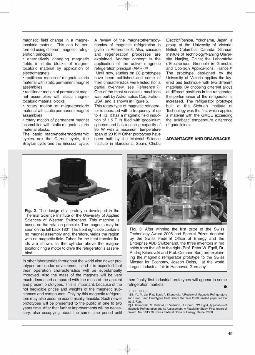
magnetic field change in a magne-tocaloric material. This can be per-formed using different magnetic refrig-eration principles:• alternatively changing magneticfields in static blocks of magne-tocaloric material by application ofelectromagnets• rectilinear motion of magnetocaloricmaterial with static permanent magnetassemblies• rectilinear motion of permanent mag-net assemblies with static magne-tocaloric material blocks • rotary motion of magnetocaloricmaterial with static permanent magnetassemblies• rotary motion of permanent magnetassemblies with static magnetocaloricmaterial blocks.The basic magnetothermodynamiccycles are the Carnot cycle, theBrayton cycle and the Ericsson cycle.
A review of the magnetothermody-namics of magnetic refrigeration isgiven in Reference 8. Also, cascadeand regeneration processes areexplained. Another concept is theapplication of the active magneticrefrigeration principal (AMR).10
Until now, studies on 28 prototypeshave been published and some oftheir characteristics were listed (for apartial overview, see Reference10).One of the most successful machineswas built by Astronautics Corporation,USA, and is shown in Figure 5.This rotary type of magnetic refrigera-tor is operated with a frequency of upto 4 Hz. It has a magnetic field induc-tion of 1.5 T, is filled with gadoliniumspheres and has a cooling capacity of95 W with a maximum temperaturespan of 20 K.10 Other prototypes havebeen built by the Material ScienceInstitute in Barcelona, Spain; Chubu
Electric/Toshiba, Yokohama, Japan; agroup at the University of Victoria,British Columbia, Canada; SichuanInstitute of Technology/Nanjing Univer-sity, Nanjing, China; the LaboratoiredʼElectronique Grenoble in Grenobleand Cooltech Applica-tions, France.11
The prototype desi-gned by theUniversity of Victoria applies the lay-ered bed technique with two differentmaterials. By choosing different alloysat different positions in the refrigerator,the performance of the refrigerator isincreased. The refrigerator prototypebuilt at the Sichuan Institute ofTechnology was the first which applieda material with the GMCE exceedingthe adiabatic temperature differenceof gadolinium.
ADVANTAGES AND DRAWBACKS
49
In other laboratories throughout the world also newer pro-totypes are under development, and it is expected thattheir operation characteristics will be substantiallyimproved. Also the mass of the magnets will be verymuch decreased compared with the mass of the ancientand present prototypes. This is important, because of thenot negligible prices and weights of the magnetic sub-stances and compounds. Only by this magnetic refrigera-tors may also become economically feasible. Such newerprototypes will be presented to the public in one to twoyears time. After that further improvements will be neces-sary, also occupying about the same time period until
then finally first industrial prototypes will appear in somerefrigeration markets.
●REFERENCES[1] B. Yu, M. Liu, P.W. Egolf, A. Kitanovski, A Review of Magnetic Refrigeratorsand Heat Pump Prototypes Built Before the Year 2008. Invited paper for theInt. J. Refr.[2] A. Kitanovski, M. Diebold, D. Vuarnoz, C. Gonin, P.W. Egolf, Application ofMagnetic Refrigeration and its Assessment: A Feasibility Study. Final report ofproject No. 101ʼ776, Swiss Federal Office of Energy, Berne, 2008.
Fig. 2. The design of a prototype developed in theThermal Science Institute of the University of AppliedSciences of Western Switzerland. This machine isbased on the rotation principle. The magnets may beseen on the left back 180°. The front right side containsno magnet assembly and, therefore, yields the regionwith no magnetic field. Tubes for the heat transfer flu-ids are shown. In the cylinder above the magne-tocaloric ring a motor to drive the refrigerator is assem-bled.
Fig. 3. After winning the frist prize of the SwissTechnology Award 2006 and Special Prizes donatedby the Swiss Federal Office of Energy and theEnterprise ABB Switzerland, the three inventors in redshirts from the left to the right (Prof. Peter W. Egolf, Dr.Andrej Kitanovski and Prof. Osmann Sari) are explain-ing the magnetic refrigerator prototype to the SwissMinster for Economy, Joseph Deiss, at the worldlargest industrial fair in Hannover, Germany.
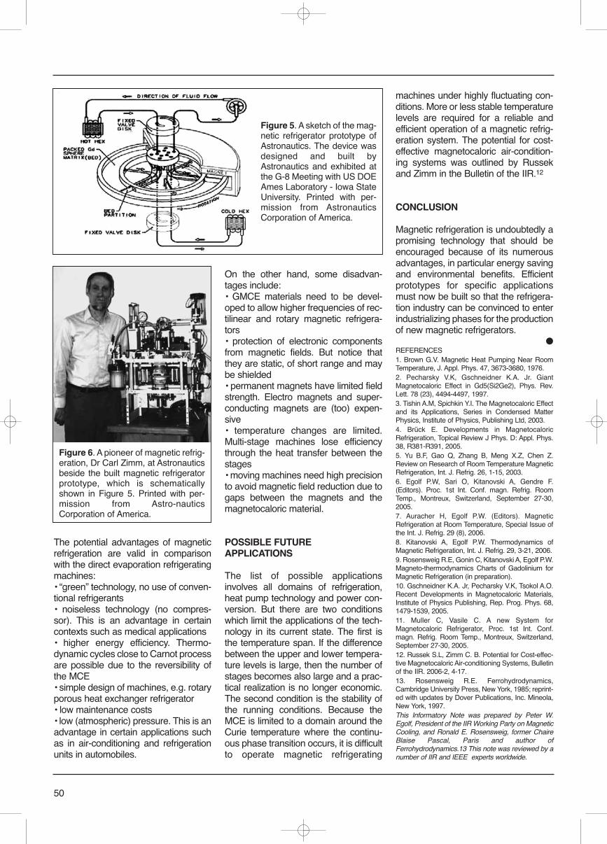
The potential advantages of magneticrefrigeration are valid in comparisonwith the direct evaporation refrigeratingmachines:• “green” technology, no use of conven-tional refrigerants• noiseless technology (no compres-sor). This is an advantage in certaincontexts such as medical applications• higher energy efficiency. Thermo-dynamic cycles close to Carnot processare possible due to the reversibility ofthe MCE• simple design of machines, e.g. rotaryporous heat exchanger refrigerator• low maintenance costs• low (atmospheric) pressure. This is anadvantage in certain applications suchas in air-conditioning and refrigerationunits in automobiles.
On the other hand, some disadvan-tages include:• GMCE materials need to be devel-oped to allow higher frequencies of rec-tilinear and rotary magnetic refrigera-tors• protection of electronic componentsfrom magnetic fields. But notice thatthey are static, of short range and maybe shielded• permanent magnets have limited fieldstrength. Electro magnets and super-conducting magnets are (too) expen-sive• temperature changes are limited.Multi-stage machines lose efficiencythrough the heat transfer between thestages• moving machines need high precisionto avoid magnetic field reduction due togaps between the magnets and themagnetocaloric material.
POSSIBLE FUTUREAPPLICATIONS
The list of possible applicationsinvolves all domains of refrigeration,heat pump technology and power con-version. But there are two conditionswhich limit the applications of the tech-nology in its current state. The first isthe temperature span. If the differencebetween the upper and lower tempera-ture levels is large, then the number ofstages becomes also large and a prac-tical realization is no longer economic.The second condition is the stability ofthe running conditions. Because theMCE is limited to a domain around theCurie temperature where the continu-ous phase transition occurs, it is difficultto operate magnetic refrigerating
machines under highly fluctuating con-ditions. More or less stable temperaturelevels are required for a reliable andefficient operation of a magnetic refrig-eration system. The potential for cost-effective magnetocaloric air-condition-ing systems was outlined by Russekand Zimm in the Bulletin of the IIR.12
CONCLUSION
Magnetic refrigeration is undoubtedly apromising technology that should beencouraged because of its numerousadvantages, in particular energy savingand environmental benefits. Efficientprototypes for specific applicationsmust now be built so that the refrigera-tion industry can be convinced to enterindustrializing phases for the productionof new magnetic refrigerators.
●REFERENCES1. Brown G.V. Magnetic Heat Pumping Near RoomTemperature, J. Appl. Phys. 47, 3673-3680, 1976.2. Pecharsky V.K, Gschneidner K.A. Jr. GiantMagnetocaloric Effect in Gd5(Si2Ge2), Phys. Rev.Lett. 78 (23), 4494-4497, 1997.3. Tishin A.M, Spichkin Y.I. The Magnetocaloric Effectand its Applications, Series in Condensed MatterPhysics, Institute of Physics, Publishing Ltd, 2003. 4. Brück E. Developments in MagnetocaloricRefrigeration, Topical Review J Phys. D: Appl. Phys.38, R381-R391, 2005.5. Yu B.F, Gao Q, Zhang B, Meng X.Z, Chen Z.Review on Research of Room Temperature MagneticRefrigeration, Int. J. Refrig. 26, 1-15, 2003.6. Egolf P.W, Sari O, Kitanovski A, Gendre F.(Editors). Proc. 1st Int. Conf. magn. Refrig. RoomTemp., Montreux, Switzerland, September 27-30,2005. 7. Auracher H, Egolf P.W. (Editors). MagneticRefrigeration at Room Temperature, Special Issue ofthe Int. J. Refrig. 29 (8), 2006.8. Kitanovski A, Egolf P.W. Thermodynamics ofMagnetic Refrigeration, Int. J. Refrig. 29, 3-21, 2006.9. Rosensweig R.E, Gonin C, Kitanovski A, Egolf P.W.Magneto-thermodynamics Charts of Gadolinium forMagnetic Refrigeration (in preparation).10. Gschneidner K.A. Jr, Pecharsky V.K, Tsokol A.O.Recent Developments in Magnetocaloric Materials,Institute of Physics Publishing, Rep. Prog. Phys. 68,1479-1539, 2005.11. Muller C, Vasile C. A new System forMagnetocaloric Refrigerator, Proc. 1st Int. Conf.magn. Refrig. Room Temp., Montreux, Switzerland,September 27-30, 2005.12. Russek S.L, Zimm C. B. Potential for Cost-effec-tive Magnetocaloric Air-conditioning Systems, Bulletinof the IIR. 2006-2, 4-17.13. Rosensweig R.E. Ferrohydrodynamics,Cambridge University Press, New York, 1985; reprint-ed with updates by Dover Publications, Inc. Mineola,New York, 1997.This Informatory Note was prepared by Peter W.Egolf, President of the IIR Working Party on MagneticCooling, and Ronald E. Rosensweig, former ChaireBlaise Pascal, Paris and author ofFerrohydrodynamics.13 This note was reviewed by anumber of IIR and IEEE experts worldwide.
50
Figure 5. A sketch of the mag-netic refrigerator prototype ofAstronautics. The device wasdesigned and built byAstronautics and exhibited atthe G-8 Meeting with US DOEAmes Laboratory - Iowa StateUniversity. Printed with per-mission from AstronauticsCorporation of America.
Figure 6. A pioneer of magnetic refrig-eration, Dr Carl Zimm, at Astronauticsbeside the built magnetic refrigeratorprototype, which is schematicallyshown in Figure 5. Printed with per-mission from Astro-nauticsCorporation of America.

SELPRO srl - via Padre Giovanni Piamarta, 5/11 - 25021 Bagnolo Mella (Brescia) Italytel. +39 (0) 030.682.16.11 r.a. - fax +39 (0) 030.622.274 - www.selproweb.com - [email protected]
the Natural air regulation
…over 30 years of experience in planning solutions to fan speed regulation
DSV 300THREE-PHASE FAN SPEED CONTROLLER
¸noiseless (NO extra-dB) no Acoustic noise during the fan speed regulation
¸compliant (NO Harmonic distortion) the ONLY in compliance with EC 61000-3-12 (Clean-Power-System)
¸cost-effective (Energy Saving)sine wave voltage regulation determines Energy Savings
¸universal (for all motors) regulation of Asynchronous Standard Motor without Special wiring
¸flexible (All-in-One) 15 preset standard software for Master & Slave regulation modes (mA-Vdc-°C)
perience in planninars of expperience dl ti t fti t f

The innovation that followsyour needs
The new products line, who has a revolutionary
front panel, allows you to use Tecnologic’s con-
trollers in each critical application:
� Dust � Powder� Liquid� Any type of flourAll these components are not a problem any-
more. The new frontal panel assures you the
complete watertigh.
A sensitive touch to followyour needs.
TECNOLOGIC S.P.A. - 27029 VIGEVANO (PV) ITALY - VIA INDIPENDENZA, 56TEL. 0039/038169871 - FAX 0039/0381698730 - [email protected] - www.tecnologic.it

An exceptional range of automatic controls,compressors and condensing units
MAKING MODERN LIVING POSSIBLE
REFRIGERATION &
AIR CONDITIONING DIVISION
Danfoss has been pioneering the development of compressor and cooling technology
since the company was founded in 1933. Throughout that time it has always been our
philosophy to work closely with our customers, listening to what they need as the
demands of their respective industries evolve.
Today, low energy consumption, quiet operation, environmental friendliness and easy
installation have become key requirements. Our current range of manual and automatic
controls, compressors and condensing units is the most technologically advanced
and efficient we have ever produced. Our products consume less energy, use fewer
materials in construction and are more reliable than ever before. And, of course, they
cool perfectly.
Respect for the
environment is central
to our design and
manufacturing philosophy
Danfoss Srl it 520B
3341

THE BEST OF TWO WORLDSSemi-hermetic Screw Compressors HS.85 – The New Performance Class
Screw Compressors Scroll Compressors Pressure VesselsReciprocating Compressors Condensing Units
AT08
.78G
B
www.bitzer.de • [email protected]
THE BEST OF TWO WORLDSSemi-hermetic Screw Compressors HS.85 – The New Performance Class
The new HS.85 combines the best of two high-performance compressor worlds: The advantages of the approved HS technology and the innovative
attributes of the CSH series. Special features of this modern construction are the slider control for infinite or stepped capacity regulation (start un-
lo ading) and the Economiser with sliding suction position, which is effective even at part load. Moreover, there is a new elaborate oil management
system: Oil filter, automatic oil stop valve, and monitoring devices for oil flow, rotation direction and oil filter clogging are integrated in the compressor.
Mounting efforts and potential leaks at the external oil distribution system are thus significantly reduced. An ideal extension of the product range
towards compressors of higher capacity, with all connections arranged on one side making them perfectly suitable for space-saving parallel operation.
Reliable. Economic. Versatile.BITZER. The heart of refrigeration systems.

Imagine a natural freeze.
Natural refrigerants like CO2 will make your cooling systems not only more cost-
efficient but also a lot safer for both people and the environment. And it will happen
sooner than you may think. Alfa Laval now has a new range of high-pressure
equipment (plate heat exchangers, unit coolers, liquid receivers and more) designed
especially for CO2 requirements. The fact that they’re from Alfa Laval is – well,
only natural.
ER
C00
050E
N 0
610

XIII EUROPEAN CONFERENCE
TECHNOLOGICAL INNOVATIONSIN AIR CONDITIONING
AND REFRIGERATION INDUSTRYWITH PARTICULAR REFERENCE TO THE ENERGY
AND ENVIRONMENTAL OPTIMIZATION, NEW REFRIGERANTS, NEW EUROPEAN REGULATION:
NEW PLANTS - THE COLD CHAIN12th - 13th June 2009
With the participation of scientists and experts fromUnited Nations Environment Programme (UNEP)
International Institute of Refrigeration (IIR)Association Française du Froid (AFF)
AREA - ASHRAE - ARI - NATE - EPEE - AICVF - RSESInstitut Français du Froid Industriel (IFFI)
Politecnico of Milano, TorinoUniversities of Ancona, Genova, Milano, Bari
Padova, Palermo, Perugia, Roma, SannioGraz (Austria), Dresden (Germany)
and all the AC&R European Associations
Politecnico di MilanoPiazza Leonardo Da Vinci, 32 - Milano (Italy)
www.centrogalileo.it