owner's pa-28-180 handbook - learn2flyhere.com · the nose gear steering mechanism also...
TRANSCRIPT

CHEROKEE 180PA-28-180
owner's Handbook
Piper Aircraft Corporation, Vero Beach, FloridaU.5. A.

NOTICE
THIS HANDBOOK IS NOT DESIGNED, NOR CAN ANYHANDBOOK SERVE, AS A SUBSTITUTE FOR ADEQÚATE ANDCOMPETENT FLIGHT INSTRÚCTION, OR KNOWLEDGE OF THECURRENT AIRWORTHINESS DIRECTIVES, THE APPLICABLEFEDERAL AIR REGULATIONS, AND ADVISORY CIRCULARS. ITIS NOT INTENDED TO «BE A GUIDE OF BASIC FLIGHTINSTRUCTION, NOR A TRAINING MANUAL.
THE HANDBOOK IS DESIGNED:1. TO HELP YOU OPERATE YOUR CHEROKEE WITH
SAFETY AND CONFIDENCE.2. TO MORE FULLY ACQUAINT YOU WITH THE BASIC
PERFORMANCE AND HANDLING CHARACTERISTICSOF THE AIRPLANE.
3. TO MORE FULLY EXPLAIN YOUR CHEROKEE'SOPERATION THAN IS PERMISSIBLE TO SET FORTH INTI-iE AIRPLANE FLIGHT MANUAL.
IF THERE IS ANY INCONSIS'i'ENCY BETWEEN THISHANDBOOK AND THE AIRPLANE PLIGHT MANUAL APPROVEDBY THE F.A.A., THE FLIGHT MANUAL SHALL GOVERN.
Revised text and illustrations shall be indicated by ablack vertical lirm in the margin opposite the change.
Additional copies of this manual, Part No. 761 513,may be obtained from your Piper Dealer.
Published byPUBLICATIONS DEPARTMENT
Piper Aircraft Corporation761 513
Issued: June 1972Revised: January 1973


SECTION 1
SPECIFICATIONS
Performance .................... .......... 1
Weights ............ . ..... ......... 2
PowerPlant.................... ......... 2
FuelandOil ................... ........... 2
Baggage ................... ... ......... 2
Dimensions ................................ 3
LandingGear............. .. ... ......... 3

CHEROKEE 180 SECTION I
SECTION I
SPECIFICATIONS
PERFORMANCE
Performance figures are for airplanes equipped for cross-countrytransportation and flown at gross weight under standard conditions atsea level or stated altitude. Any changes in equipment may result inchanges in performance.
Take-off Ground Run (S.L. Std., maximum effort, 25°
flap) (ft) 720Take-off over 50-ft Barrier S.L. Std., (maximum effort,
25°flap) (ft) 1625Best Rate of Climb Speed (mph) 85Rate of Climb (ft per min) 725Service Ceiling (ft) 14,150Absolute Ceiling (ft) 16,500Top Speed (mph) 148Optimum Cruise Speed (TAS) (75% power,
optimum altitude, leaned to best power) (mph) 141Cruising Range (75% power, optimum altitude
leaned to best economy, no reserves or climballowance) (mi) 686
Optimum Cruising Range (55% power, 10,000 ft,leaned to best economy, no reserves or climballowance (mi) 706
Stalling Speed CAS (flaps down) (mph) 61- Stalling Speed CAS (flaps up) (mph) 68
Landing Roll S.L. Std., (flaps down) (ft) 635*
Landing Roll over 50-ft Barrier S.L. Std., (ft) 1185*
*This value applies only for the conditions indicated on the landingdistance versus density altitude chart.
761 513 1720615

SECTION I CHEROKEE 180
SPECIFICATIONS (cont.)
WEIGHTS
Gross Weight (lbs) 2450Empty Weight (Standard) (lbs) 1384*
USEFUL LOAD (Standard) (lbs) 1066*
POWER PLANT
Engine (Lycoming) O-360-A4ARated Horsepower 180Rated Speed (rpm) 2700Bore (in.) 5.125Stroke (in.) 4.375Displacement (cu in.) 361.0Compression Ratio 8.5:1Dry Weight (lbs) 285Propeller 76EM8S5-0-60
FUEL AND OIL
Fuel Capacity (U.S. gal) Usable 48Oil Capacity (qts) 8Fuel, Aviation Grade (min octane) 100/130
BAGGAGE
Maximum Baggage (lbs) 200
Baggage Space (cu ft) 24Baggage Door Size (in.) 20 x 22
* Weight varies with each aircraft
2 761513720615

CHEROKEE 180 SECTION I
SPECIFICATIONS (cont.)
DIMENSIONS
Wing Span (ft) 32Wing Area (sq ft) 170Wing Loading (lbs per sq ft) 14.4Length (ft) 24.0Height (ft) 7.8Power Loading (lbs per hp) 13.6
LANDING GEAR
Wheel Base (ft) 6.7Wheel Tread (ft) 10Tire Pressure (psi) Nose 24
Main 24Tire Size Nose (4 ply rating) 6.00 x 6
Main (4 ply rating) 6.00 x 6
761 513 3
720615

SECTION I CHEROKEE 180
50"
3 "
2.50"
10'
- 24' 09"
T .ß0"
---8' 8.4"
4 761513720615

SECTION 11
DESIGN INFORMATION
EngineandPropeller ............ .. ......... 5
Structures.......... ..... . ... .......... 5
LandingGear ........... ... . . .......... 6
ControlSystems ......... .... ........ 7
FuelSystem ........ ....... 7
Electrical System . . . . . . . . . . . . . . . . . . . . 9
Heating and Ventilating System . . . . . . . . . . . . . . . . . . 13
CabinFeatures .......... . . ........ 13
Optional Equipment . . . . . . . . . . . . . . . . . 16

CHEROKEE 180 SECTION 11
SECTION 11
DESIGN INFORMATION
ENGINE AND PROPELLER
The Cherokee 180 is powered by a Lycoming O-360-A4A fourcylinder, direct drive, horizontally opposed engine rated at 180 HP at2700 RPM. It is furnished with a starter, 60 ampere 12 volt alternator,shielded ignition, vacuum pump drive, fuel pump, and a dry,automotive type carburetor air filter.
The exhaust system is of the cross-over type to reduce backpressure and improve performance, It is made entirely from stainlesssteel and is equipped with dual mufflers. A heater shroud around themufflers is provided to supply heat for the cabin and windshielddefrosting.
The Sensenich 76EM8S5-0-60 fixed-pitch propeller is made from a
one-piece alloy forging.
STRUCTURES
All structures are of aluminum alloy construction and are designedto ultimate load factors well in excess of normal requirements. Allexterior surfaces are primed with etching primer and painted withacrylic lacquer.
The wings are attached to each side of the fuselage by inserting thebutt ends of the respective main spars into a spar box carry-through
which is an integral part of the fuselage structure, providing in effect acontinuous main spar with splices at each side of the fuselage. There arealso fore and aft attachments at the rear spar and at an auxiliary frontspar.
761 513 5720615

SECTION Il CHEROKEE 180
The wing airfoil section is a laminar flow type, NACA652-415 withthe maximum thickness about 40% aft of the leading edge. This permitsthe main spar carry-through structure to be located under the rear seatproviding unobstructed cabin floor space ahead of the rear seat.
LANDING GEAR
The three landing gears use a Cleveland 6.00 x 6 wheel, the mainwheels being provided with Cleveland single disc hydraulic brakeassemblies, No. 30-55. All wheels use 6.00 x 6 four ply tires with tubes.
The nose gear is steerable through a 44 degree are by use of therudder pedals. A spring device is incorporated in the rudder pedaltorque tube assembly to aid in rudder centering and to provide rudder
trim. The nose gear steering mechanism also incorporates a hydraulicshimmy dampener.
The three struts are of the air-oil type, with the normal extension
being 3.25 inches for the nose gear and 4.50 inches for the main gear.The standard brake system for the Cherokee consists of a hand
lever and master cylinder which is located below and behind the leftcenter of the instrument sub-panel. The brake fluid reservoir is installedon the top left front face of the firewall. The parking brake isincorporated in the master cylinder and is actuated by pulling back onthe brake lever, depressing the knob attached to the handle andreleasing the brake lever. To release the parking brake, pull back on thelever to disengage the catch mechanism and allow the handle to swingforward.
Optional toe brakes are available to supplement the standard handlever and parking brake system.
6 761513720615

CHEROKEE 180 SECTION II
CONTROL SYSTEMS
Dual controls are provided as standard equipment with a cablesystem used between the controls and the surfaces. The horizontal tailis of the Flying Tail type (stabilator), with a trim tab mounted on the
trailing edge of the stabilator to reduce the control system forces. Thistab is actuated by a control wheel on the floor between the front seats.The stabilator provides extra stability and controllability with less size,
drag and weight than conventional tail surfaces. The ailerons areprovided with a differential action which tends to reduce adverse yawin turning maneuvers, and which also reduces the amount ofcoordination required in normal turns. A rudder trim adjustment ismounted on the right side of the pedestal below the throttle quadrantand permits directional trim as needed in flight.
The flaps are manually operated, balanced for light operatingforces and spring-loaded to return to the up position. A past-center lockincorporated in the actuating linkage holds the flap when it is in the upposition so that it may be used as a step on the right side. The flap willnot support a step load except when in the full up position, so it mustbe completely retracted when used as a step. The flaps have threeextended positions: 10, 25 and 40 degrees.
FUEL SYSTEM
Fuel is stored in two twenty-five gallon (24 gal. usable) tankswhich are secured to the leading edge structure of each wing by screws
and nut plates. This allows easy removal for service or inspection.The fuel selector control is located on the left side-panel, forward
of the pilot's seat. The button on the selector must be depressed and
held while the handle is moved to the OFF position. The buttonreleases automatically when the handle is moved back into the ONposition.
An auxiliary electric fuel pump is provided in case of failure of theengine driven pump. The electric pump should be on for all take-offsand landings, and when switching tanks. The pump switch is located inthe switch panel above the throttle quadrant.
761 513 7730122

SECTION II CHEROKEE 180
FUELPRESSUREGAUGE
FUELQUANTITYGAUGES
ENGINEFUELPUMP
litt rÎr
DRAIN
ELPUMP
VENT
SASCOLATOR
FUELSELECTORVALVE
VENT
LEFTTANK__,
RIGHTTANK
U UDRAIN ORAIN
FUEL SYSTEMSCHEMATIC
8 761513720615

CHEROKEE 180 SECTION II
Each tank has an individual quick drain loacated at the bottom,inboard rear corner, and should be drained to check for water beforeeach flight. The fuel strainer, which is also equipped with a quick drain,is located on the front lower left corner of the firewall. This strainershould be drained regularly to check for water or sedimentaccumulation. To drain the lines from the tanks, the tank selector valve
must be switched to each tank in turn, with the electric pump on, and
the gascolator drain valve opened.Fuel quantity and pressure are indicated on gauges located in a
cluster on the left side of the instrument panel.
ELECTRICAL SYSTEM
The electrical system includes a 12 volt 60 amp alternator, battery,voltage regulator, overvoltage relay and master switch relay. Thebattery is mounted in a stainless steel box immediately aft of thebaggage compartment. The regulator and overvoltage relay are locatedon the forward left side of the fuselage behind the instrument panel.
Electrical switches are located on the right center instrument panel,and the circuit breakers are located on the lower right instrument panel.A rheostat-switch on the left side of the switch panel controls thenavigation lights and the dome instrument light. It also dims the domelight. The similar switch on the right side controls and dims the panellights.
eeeeooooseeeeALTERNATOR ENGINE FUEL STALL AUTO PITOT TUANS PtTCH START
GUTPUT FIELD I GROUP I PUMP I 1 lwAANING I I PILOT HEAT | BANK i TRIM i SACC
oeeeeeeeeecesINSTRUMENTLIGHT NAV NTi- LANDtNG AV-COM NAV-COM ADF AUDIO AIA DME TRANSPANEL OVEAHEA LIGHTS LtBHT LlGHTS : 2 PANEL CONO. PONDER
DOOR REMOVEDFÒR CLARITY
Circuit Breaker Panel
761 513 9730122

SECTION II CHEROKEE 180
The alternator system offers many advantages over the generatorsystem both in operation and maintenance. The main advantage is fullelectrical power output at lower engine RPM. This is a greatimprovement for radio and electrical equipment operation. Since thealternator output is available at all times, the battery will be chargingfor a greater percentage of use. This will make cold-morning startingeasier.
Standard accessories include a starter, electric fuel pump, stallwarning indicator, cigar lighter, fuel gauge and ammeter. The navigationlights, anti-collision light, landing light, instrument lighting and cabindome light are optional. Circuits will handle an entire complement ofcommunications and navigational equipment.
The words "master switch" used hereafter in this manual indicateboth sides of the switch, battery side "BAT" and alternator side "ALT"are to be depressed simultaneously to OFF or ON as directed.
Unlike previous generator systems, the ammeter does not indicatebattery discharge; rather it displays in amperes the load placed on thealternator. With all electrical equipment off (except master switch) theammeter will be indicating the amount of charging current demandedby the battery. As each item of electrical equipment is turned on, thecurrent will increase to a total appearing on the ammeter. This total
includes the battery. The maximum continuous load for night flight,with radios on, is about 30 amperes. This 30 ampere value, plusapproximately two amperes for a fully charged battery, will appearcontinuously under these flight conditions. The amount of currentshown on the ammeter will tell immediately if the alternator system isoperating normally, as the amount of current shown should equal thetotal amperage drawn by the equipment which is operating.
If no output is indicated on the ammeter during flight, reduce the
electrical load by turning off all unnecessary electrical equipment.Check both 5 ampere field breaker and 60 ampere output breaker andreset if open. If neither circuit breaker is open, turn off the "ALT"switch for 30 seconds to reset the overvoltage relay. If ammeter
continues to indicate no output, maintain minimum electrical load andterminate flight as soon as practical.
Maintenance on the alternator should prove to be a minor factor.Should service be required, contact the local Piper Dealer.
761 51310730122

CHEROKEE 180 SECTION II
HEATING AND VENTILATING SYSTEM
Heat for the cabin interior and the defroster system is provided bya heater muff attached to the exhaust system. The amount of heatdesired can be regulated with the controls located on the far right sideof the instrument panel.
The air flow can be regulated between the front and rear seats bylevers located on top of the heat ducts next to the console.
Fresh air inlets are located in the leading edge of the wing at theintersection of the tapered and straight sections. A large adjustableoutlet is located on the side of the cabin near the floor at each seatlocation. Cabin air is exhausted through an outlet located below therear seat.
CABIN FEATURES
The instrument panel of the Cherokee is designed to accommodatethe customary advanced flight instruments and the normally requiredpower plant instruments. The Artificial Horizon and Directional Gyroare vacuum operated through use of a vacuum pump installed on theengine, while the Turn and Bank instrument is electrically operated. Avacuum gauge is mounted on the far right side of the instrument panel.A natural separation of the flight group and the power group isprovided by placing the flight group in the upper instrument panel andthe power group in the center and lower instrument panels. The radiosand circuit breakers located on the right hand instrument panel haveextra circuits provided for a complete line of optional radio equipment.The microphone is located on the control quadrant covet, seeillustration page 14, item 42.
The cabin interior includes a pilot storm window, two sun visors,ash trays, two map pockets, and pockets on the backs of each frontseat. The front seats are adjustable fore and aft for pilot-passengercomfort and ease of entry and exit. Arm rests are also provided for thefront seats.
761 513 13720615

CHEROKEE 180 SECTION II
A single strap shoulder harness controlled by an inertia reel isstandard equipment for the front seats, and is offered as an option forthe rear seats. The shoulder strap is routed over the shoulder adjacentto the windows and attached to the lap belt in the general area of the
person's inboard hip.A check of the inertia reel mechanism is made by pulling sharply
on the strap. The reel will lock in place under this test and prevent thestrap from extending. Under normal movement the strap will extend
and retract as required.The 24 cubic foot baggage area may be reached from the cabin or
through a large 20 x 22 inch outside door.
761 513 15720615

SECTION 11 CHEROKEE 180
AIR CONDITIONING*
The air conditioning system is a recirculating air system. The majoritems include; evaporator, condenser, compressor, blower, switches andtemperature controls.
The evaporator is located behind the left rear side of the baggagecompartment. This cools the air that is used for air conditioning.
The condenser is mounted on a retractable scoop located on thebottom of the fuselage and to the rear of the baggage compartmentarea. The scoop extends when the air conditioner is "ON" and retracts
to a flush position when the system is "OFF."The compressor is mounted on the forward right underside of the
engine. It has an electric clutch which automatically engages ordisengages the compressor to the belt drive system of the compressor.
An electrical blower is mounted on the aft side of the rear cabinpanel. Air from the baggage area is drawn through the evaporator bythe blower and distributed through an overhead duct to individualoutlets located adjacent to each occupant.
The switches and temperature control are located on the lowerright side of the instrument panel in the climate control center panel.The temperature control regulates the desired temperature of the cabin.Turn the control clockwise for increased cooling, counterclockwise fordecreased cooling.
Located inboard of the temperature control is the fan speed switchand the air conditioning "ON-OFF" switch. The fan can be operatedindependently of the air conditioning. However, it must be on for airconditioner operation. Turning either switch off will disengage thecompressor clutch and retract the condenser door. Cooling air shouldbe felt within one minute after the air conditioner is turned on.*Optional Equipment
16 761513
720615

CHEROKEE 180 SECTION II
NOTE
If the system is not operating in 5 minutes turn thesystem "OFF" until the fault is corrected.
The "FAN" switch allows operation of the fan with the airconditioner turned "OFF" to aid cabin air circulation if desired. A"LOW," "MED" or "HIGH" flow of air can be selected to the airconditioner outlets located in the overhead duct. The outlets can beadjusted or turned off by each occupant to obtain individual coolingeffect.
The "DOOR OPEN" indicator light is located to the left of theradio stack in front of the pilot. The light illuminates whenever thecondenser door is open and remains on until the door is closed.
A circuit breaker located on the circuit breaker panel protects theair conditioning electrical system.
Whenever the throttle is in the full throttle position, it actuates amicro switch which disengages the compressor and retracts the scoop.This is done to obtain maximum power and maximum rate of climb.The fan continues to operate and the air will remain cool forapproximately one minute. When the throttle is retarded approximately1/4 inch, the clutch will engage and the scoop will extend, again
supplying cool, dry air.
761 513 17720615

SECTION 11 CHEROKEE 180
NOTES
18 761513720615

SECTION III
OPERATING INSTRUCTIONS
Preflight...... .... ....................... 19
StartingEngine........... .................. 20
Warm-UpandGroundCheck ...................... 22
Take-Off................................. 23
Climb ...................................23
Stalls ................................... 24
Cruising ................................ .24
ApproachandLanding ......................... 25
StoppingEngine ............................. 26
EnginePowerLoss............................ 26
Mooring .................................. 27
WeightandBalance ........................... 27
OperatingTips .............. ............... 27
Optional Equipment . . . . . . . . . . . . . . . . . . . 30

CHEROKEE 180 SECTION III
SECTION III
OPERATING INSTRUCTIONS
PREFLIGHT
1. Master switch and ignition OFF.2. a. Check for external damage and operational interference of
control surfaces or hinges.b. Insure that wings and control surfaces are free of snow,
ice or frost.3. a. Visually check fuel supply and secure caps.
b. Drain fuel tank sumps (two).
761 513 19720615

SECTION III CHEROKEE 180
c. Drain fuel system sump (left side of aircraft).d. Check that fuel system vents are open.
e. Check main landing gear shock struts for proper inflation(approximately 4.50 inches showing).
f. Check tires for cuts, wear and proper inflation.g. Check brake blocks and discs for wear and damage.
4. a. Check windshield for cleanliness.b. Check propeller and spinner for defects or nicks.c. Check for obvious fuel or oil leaks.d. Check oil level (insure dipstick is properly seated).e. Check cowling and inspection covers for security.f. Check nose wheel tire for inflation and wear.g. Check nose gear shock strut for proper inflation
(approximately 3.25 inches showing).h. Check for foreign matter in air inlet.
5. a. Stow tow-bar and control locks if used.b. Check baggage for storage and security.c. Close and secure the baggage compartment door.
6. a. Upon entering airplane remove seat belt securing contrólwheel. Check that all primary flight controls operate properly.
b. Close and secure cabin door.c. Check that required papers are in order and in the
airplane.d. Fasten seat belts and shoulder harness. Check function of
inertia reel.
STARTING ENGINE
1. Set parking brake ON.2. Set the carburetor heat control in the full COLD position.3. Select the desired tank with fuel selector valve.
Starting Engine When Cold:1. Open throttle approximately 1/4 inch.2. Turn the master switch ON.3. Turn the electric fuel pump ON.4. Move the mixture control to FULL RICH.5. Engage the starter by rotating magneto switch clockwise and
pressmg m.
20 761513730122

CHEROKEE 180 SECTION III
6. When the engine fires, advance throttle to desired setting. Ifthe engine does not fire within five to ten seconds, disengage starter andprime with one to three strokes of the priming pump. Repeat the
starting procedure.
Starting Engine When Hot:
1. Open the throttle approximately 1/2 inch.2. Turn the master switch ON.3. Turn the electric fuel pump ON.4. Put mixture control in IDLE CUT-OFF.
5. Engage the starter by rotating magneto switch clockwise andpressing in. When the engine fires, advance the mixture control andmove the throttle to desired setting.
Starting Engine When Flooded:1. Open the throttle full.2. Turn the master switch ON.3. Turn the electric fuel pump OFF.4. Put mixture control in IDLE CUT-OFF.5. Engage the starter by rotating magneto switch clockwise and
pressing in. When the engine fires, advance the mixture control andretard the throttle.
Starting With External Power Source:An optional feature known as Piper External Power (PEP) allows
the operator to use an external battery to crank the engine withouthaving to gain access to the aircraft battery.
The procedure is as follows:1. Turn aircraft MASTER SWITCH to OFF.2. Connect RED lead of PEP kit jumper cable to POSITIVE (+)
terminal of external 12 volt battery and BLACK lead to NEGATIVE (-)terminal.
3. Insert plug of jumper cable into socket located on aircraftfuselage.
4. Turn aircraft MASTER SWITCH to ON and proceed withNORMAL engine starting technique.
761 513 21720615

SECTION III CHEROKEE 180
5. After engine has been started, turn MASTER SWITCH to OFFand remove jumpercable plug from aircraft.
6. Turn aircraft MASTER SWITCH to ON and check alternatorammeter for indication of output. DO NOT ATTEMPT FLIGHT IFTHERE IS NO INDICATION OF ALTERNATOR OUTPUT.
When the engine is firing evenly, advance the throttle to 800 RPM.If oil pressure is not indicated within thirty seconds, stop the engine
and determine the trouble. In cold weather it will take a few secondslonger to get an oil pressure indication. If the engine has failed to start,refer to the "Lycoming Operating Handbook, Engine Troubles andTheir Remedies."
Starter manufacturers recommend that cranking periods be limitedto thirty seconds with a two minute rest between cranking periods.Longer cranking periods will shorten the life of the starter.
WARM-UP AND GROUND CHECK
Warm-up the engine at 800 to 1200 RPM for not more than twominutes in warm weather, four minutes in cold weather. Avoidprolonged idling at low RPM as this practice may result in fouled sparkplugs. If necessary to hold before take-off, it is recommended that theengine be idled at 1200 RPM.
The magnetos should be checked at 2000 RPM and the drop off oneither magneto should not exceed 175 RPM and should be within 50RPM of the other. Prolonged operation on one magneto should beavoided.
Check vacuum gauge, indicator should read 5" Hg ± .1" Hg at 2000RPM.
Check both the oil temperature and pressure. The temperature maybe low for some time if the engine is being run for the first time of the
day, but as long as the pressure is within limits the engine is ready fortake-off.
Carburetor heat should also be checked prior to take-off to be surethat the control is operating properly and to clear any ice which mayhave formed during taxiing. Avoid prolonged ground operation with
carburetor heat ON as the air is unfiltered.
22 761513730122

CHEROKEE 180 SECTION III
Operation of the engine driven fuel pump should be checked whiletaxiing or during pretake-off engine run up by switching off the electricfuel pump and observing fuel pressure. The electric fuel pump shouldbe on during take-off to prevent loss of power should the engine drivenpump fail. The engine is warm enough for take-off when the throttlecan be opened without the engine faltering. For air conditioner groundcheck refer to page 30.
TAKE-OFF
Just before take-off the following items should be checked:
1. Fuel on proper tank 7. Seat backs erect2. Electric fuel pump - on 8. Fasten belts/harness3. Engine gages checked 9. Trim tab - set4. Flaps - set 10. Controls - free5. Carb. heat off 11. Door - latched6. Mixture - set 12. Air conditioner - off
The take<>ff technique is conventional for the Cherokee. The tabshould be set slightly aft of neutral, with the exact setting determinedby the loading of the aircraft. Allow the airplane to accelerate to 50 to60 MPH, then ease back on the wheel enough to let the airplane flyitself off the ground. Premature raising of the nose, or raising it to anexcessive angle will result in a delayed take-off. After take-off let theaircraft accelerate to the desired climb speed by lowering the noseslightly.
Take-offs are normally made with flaps up. However, for shortfield take-offs, and for take-offs under difficult conditions such as deepgrass or on a soft surface, distances can be reduced appreciably bylowering flaps to 25°.
CLIMB
The best rate of climb at gross weight will be obtained at 85 MPH.The best angle of climb may be obtained at 74 MPH. At lighter thangross weight these speeds are reduced somewhat. For climbing en routea speed of 100 MPH is recommended. This will produce better forwardspeed and increased visibility over the nose during the climb. The air
conditioner may be turned on after all obstacles have been cleared.
761 513 23730122

SECTION III CHEROKEE 180
STALLS
All controls are effective at speeds down through the stalling speed,and stalls are gentle and easily controlled.
Stall speed chart on following page is at gross weight. Stall speedsat lower weights will be correspondingly less.
STALL SPEED TABLE
Angle of Bank Flaps 40° Flags Retractedo° 61 MPH 68 MPH
20° 63 MPH 70 MPH40° 70 MPH 78 MPH60° 86 MPH 96 MPH
Power Off - Gross Weight 2450 lbs.
CRUISING
The cruising speed is determined by many factors including powersetting, altitude, temperature, loading and equipment installed on the
airplane.The normal cruising power is 75% of the rated horsepower of the
engine. True airspeeds which may be obtained at various altitudes andpower settings can be determined from the charts in Section IV of this
handbook.Use of the mixture control in cruising flight reduces fuel
consumption significantly, especially at higher altitudes. The mixture
should be leaned during cruising operation above 5000 feet altitude andat pilot's discretion at lower altitudes when 75% power or less is beingused. If any doubt exists as to the amount of power being used, the
mixture should be in the FULL RICH position for all operations under5000 feet.
24 761513720615

CHEROKEE 180 SECTION III
To lean the mixture, pull the mixture control until the engine
becomes rough, indicating that the lean mixture limit has been reached
in the leaner cylinders. Then enrich the mixture by pushing the controltowards the instrument panel until engine operation becomes smooth.
If the airplane is equipped with the optional exhaust gastemperature (EGT) gauge, a more accurate means of leaning is availableto the pilot. For this procedure, refer to the AVCO LycomingOperator's Manual.
In order to keep the airplane in best lateral trim during cruisingflight, the fuel should be used alternately from each tank. It isrecommended that one tank be used for one hour after take-off, thenthe other tank be used for two hours, then return to the first tank,which will have approximately one and one half hours of fuel remainingif the tanks were full at take-off. The second tank will containapproximately one half hour of fuel. Do not run tanks completely dryin flight.
APPROACH AND LANDING
Before landing check list:1. Fuel on proper tank 4. Seat backs erect2. Mixture - rich 5. Flaps - set (115 MPH)3. Electric fuel pump - on 6. Fasten belts/harness
7. Air conditioner - off
The airplane should be trimmed to an approach speed of about 85MPH with flaps up. The flaps can be lowered at,speeds up to 115 MPH,if desired, and the approach speed reduced 3 MPH for each additionalnotch of flaps. Carburetor heat should not be applied unless there is anindication of carburetor icing, since the use of carburetor heat causes a
reduction in power which may be critical in case of a go-around. Fullthrottle operation with heat on is likely to cause detonation.
The amount of flap used during landings and speed of the aircraft
at contact with the runway should be varied according to the landingsurface and conditions of wind and airplane loading. It is generally goodpractice to contact the ground at minimum possible safe speedconsistent with existing conditions.
761 513 25720615

SECTION III CHEROKEE 180
Normally, the best technique for short and slow landings is to use
full flap and enough power to maintain the desired airspeed andapproach flight path. Reduce the airspeed during flare out and contactthe ground close to stalling speed. After ground contact hold the nosewheel off as long as possible. As the airplane slows down, drop the noseand apply brakes. There will be less chance of skidding the tires if the
flaps are retracted before applying the brakes. Braking is most effectivewhen back pressure is applied to the control wheel, putting most of theairplane weight on the main wheels. In high wind conditions,particularly in strong crosswinds, it may be desirable to approach the
ground at higher than normal speeds with partial or no flaps.
STOPPING ENGINE
At the pilot's discretion, the flaps should be raised and the electricfuel pump turned off. After parking, the air conditioner and radios
should be turned off and the engine stopped by pulling the mixturecontrol to idle cut-off. The throttle should be left full aft to avoidengine vibration while stopping. Then the magneto and master switchesshould be turned off and the parking brake set.
ENGINE POWER LOSS
The most common cause of engine power loss is mismanagement ofthe fuel. Therefore, the first step to take after engine power loss is tomove the fuel selector valve to the tank not being used. This will oftenkeep the engine running even if there is no apparent reason for theengine to stop on the tank being used.
If changing to another tank does not restore the engine:1. Check fuel pressure and turn on electric fuel pump if off.
2. Push mixture control to full "RICH."3. Check ignition switch. Turn to best operating magneto - left,
right, or both.
26 761513720615

CHEROKEE 180 SECTION III
MOORING
The Cherokee should be moved on the ground with the aid of thenose wheel tow-bar provided with each plane and secured in thebaggage compartment. Tie down ropes may be secured to ringsprovided under each wing and to the tail skid. The aileron and
stabilator controls should be secured by looping the seat belt through
the control wheel and pulling it tight. The rudder is held in position byits connections to the nose wheel steering and normally does not haveto be secured. The flaps are locked when in the full up position and
should be left retracted.
WEIGHT AND BALANCE
It is the responsibility of the owner and pilot to determine that theairplane remains within the allowable weight vs. center of gravityenvelope while in flight. For weight and balance data see the AirplaneFlight Manual and Weight and Balance form supplied with eachairplane.
OPERATING TIPS
The following Operating Tips are of particular value in theoperation of the Cherokee.
1. Learn to trim for take-off so that only a very light backpressure on the wheel is required to lift the airplane off the ground.
2. The best speed for take-off is about 60 MPH under normalconditions. Trying to pull the airplane off the ground at too low anairspeed decreases the controllability of the airplane in event of enginefailure.
3. Flaps may be lowered at airspeeds up to 115 MPH. To reduceflap operating loads, it is desirable to have the airplane at a slower speedbefore extending the flaps.
4. Before attempting to reset any circuit breaker, allow a two tofive minute cooling off period.
761 513 27720615
SECTION III CHEROKEE 180
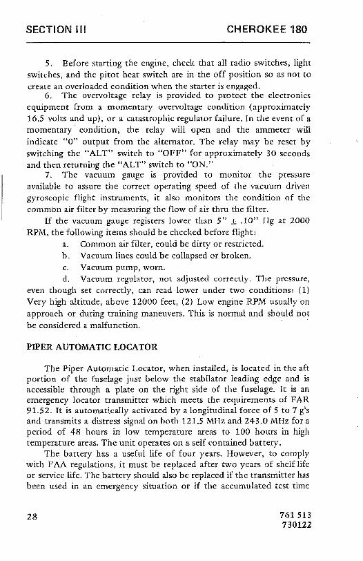
5. Before starting the engine, check that all radio switches, lightswitches, and the pitot heat switch are in the off position so as not tocreate an overloaded condition when the starter is engaged.
6. The overvoltage relay is provided to protect the electronicsequipment from a momentary overvoltage condition (approximately16.5 volts and up), or a catastrophic regulator failure. In the event of amomentary condition, the relay will open and the ammeter willindicate "0" output from the alternator. The relay may be reset byswitching the "ALT" switch to "OFF" for approximately 30 secondsand then returning the "ALT" switch to "ON."
7. The vacuum gauge is provided to monitor the pressureavailable to assure the correct operating speed of the vacuum drivengyroscopic flight instruments, it also monitors the condition of thecommon air filter by measuring the flow of air thru the filter.
If the vacuum gauge registers lower than 5" ± .10" Hg at 2000RPM, the following items should be checked before flight:
a. Common air filter, could be dirty or restricted.b. Vacuum lines could be collapsed or broken.c. Vacuum pump, worn.d. Vacuum regulator, not adjusted correctly. The pressure,
even though set correctly, can read lower under two conditions: (1)Very high altitude, above 12000 feet, (2) Low engine RPM usually onapproach or during training maneuvers. This is normal and should notbe considered a malfunction.
PIPER AUTOMATIC LOCATOR
The Piper Automatic Locator, when installed, is located in the aftportion of the fuselage just below the stabilator leading edge and isaccessible through a plate on the right side of the fuselage. It is anemergency locator transmitter which meets the requirements of FAR91.52. It is automatically activated by a longitudinal force of 5 to 7 g'sand transmits a distress signal on both 121.5 MHz and 243.0 MHz for aperiod of 48 hours in low temperature areas to 100 hours in hightemperature areas. The unit operates on a self contained battery.
The battery has a useful life of four years. However, to complywith FAA regulations, it must be replaced after two years of shelf lifeor service life. The battery should also be replaced if the transmitter hasbeen used in an emergency situation or if the accumulated test time
28 761513730122

CHEROKEE 180 SECTION III
exceeds one hour. The replacement date is marked on the transmitterlabel.
The unit has a three position selector switch placarded "OFF,""ARM" and "ON." The "ARM" position is provided to set the unit tothe automatic position so that it will transmit only after impact andcontinue to transmit until the battery power is drained to depletion orthe switch is manually moved to the "OFF" position. The "ARM"position is selected when the locator is installed at the factory andshould remain in that position whenever the unit is installed in theaircraft. The "ON" position is provided so the unit can be used as aportable transmitter or in the event the automatic feature was nottriggered by impact or to check the function of the transmitterperiodically.
The "OFF" position is provided for the purpose of changing thebattery or if used as a portable transmitter or rearming the unit if itshould be activated for any reason.
NOTEIf the switch has been placed in the "ON" positionfor any reason, the "OFF" position has to be selectedbefore selecting "ARM." If "ARM" is selecteddirectly from the "ON" position the transmitter willcontinue to transmit in the "ARM" position.
Attached to the unit is a portable antenna, provided so that thelocator may be removed from the aircraft, in case of an emergency, andused as a portable signal transmitter.
The locator should be checked during the Ground Check to makecertain the unit has not been accidently activated. Check by tuning aradio receiver to 121.5 MHz. If you hear an oscillating audio sound thelocator may have been activated and should be turned off immediately.Reset to "ARM" position and check again to insure against outside
interference.
761 513730122 29

SECTION Ill CHEROKEE 180
OPTIONAL EQUIPMENT
AIR CONDITIONING
To operate the air conditioning system either on the ground or inflight:
1. Start the engine (groundoperation).2. Turn the air conditioning "Master" switch to "ON."3. Turn "TEMP" control to desired temperature. Clockwise
rotation increases cooling.4. Select desired "FAN" position, "LOW," "MED" or "HIGH."
AIR CONDITIONER OPERATIONAL CHECK PROCEDURE
Prior to take-off the air conditioner should be checked for properoperation as follows:
1. Check aircraft Master Switch ON.2. Select desired "FAN" position, "LOW," "MED" or "HIGH."3. Turn the air conditioner control switch to "ON" - the "Air
Cond. Door Open" warning light will turn on, thereby indicating properair conditioner condenser door actuation.
4. Turn the air conditioner control switch to "OFF" - the "AirCond. Door Open" warning light will go out, thereby indicating the airconditioner condenser door is in the up position.
5. If the "Air Cond. Door Open" light does not respond as
specified above, an air conditioner system or indicator bulbmalfunction is indicated, and further investigation should be conductedprior to flight.
The above operational check may be performed during flight if an
inflight failure is suspected.
30 761 513720615

CHEROKEE 180 SECTION 111
AIR CONDITIONER EFFECTS ON AIRPLANE PERFORMANCE
Operation of the air conditioner will cause slight decreases in thecruise speed and range of the Cherokee 180. Power from the engine isrequired to run the compressor, and the condenser door, when
extended, causes a slight increase in drag. When the air conditioner isturned off there is normally no measurable difference in climb, cruiseor range performance of the airplane.
NOTE
To insure maximum climb performance the airconditioner must be turned off manually beforetake-off to disengage the compressor and retract the
condenser door. Also the air conditioner must beturned off manually before the landing approach inpreparation for a possible go-around.
Although the cruise speed and range are only slightly affected bythe air conditioner operation, these changes should be considered inpreflight planning. To be conservative, the following figures assume thatthe compressor is operating continuously while the airplane is airborne.This will be the case only in extremely hot weather.
1. The decrease in true airspeed is approximately 5 mph at allpower settmgs.
2. The decrease in range may be as much as 37 statue miles forthe 50 gaL capacity.
761 513 31720615

SECTION III CHEROKEE 180
NOTE
To read power from the Power vs. Density AltitudeChart in this manual, add 50 rpm to the valueobserved on the tachometer when the air conditioner
is operating.
The climb performance of Cherokee 180 is not compromised
measurably with the air conditioner operating since the compressor isde-clutched and the condenser door is retracted, both automatically,when a full throttle position is selected. When the full throttle positionis not used or in the event of a malfunction which caused thecompressor to operate and the condenser door to be extended, a
decrease in rate of climb of as much as 100 fpm can be expected.Should a malfunction occur which prevents condenser door retractionwhen the compressor is turned off, a decrease in rate of climb of asmuch as 50 fpm can be expected.
32 761513720615

SECTION IV
EMERGENCY PROCEDURES
Introduction . . - - - - - · - - · - . - - · - - - · · · 33
GroundOperations -··-········-- ······ 33
Take-Off......... . . - · · -- -··-· - 34
InFlight .......... . . .. .......... 35
Power Off Landing · · · · 36
Fire 37
Loss of Oil Pressure . . . . . 37
LossofFuelPressure .. .. ... ....... ... .. . . .. 38
HighOilTernperature ............ ........ 38
Alternator Failure . . . . . . . . . . 38
Engine Roughness . . . . . . . . . . 38
Spins ····· ··· - 40
OpenDoor ......... . ........- 40

CHEROKEE 180 SECTION IV
SECTION IV
EMERGENCY PROCEDURES
INTRODUCTION
This section contains procedures that are recommended if anemergency condition should occur during ground operation, take-off,
or in flight. These procedures are suggested as the best course of actionfor coping with the particular condition described, but are not asubstitute for sound judgementand common sense. Since emergencies
rarely happen in modern aircraft, their occurrence is usually unexpected,and the best corrective action may not always be obvious. Pilots shouldfamiliarize themselves with the procedures given in this section and beprepared to take appropriate action should an emergency arise.
Most basic emergency procedures, such as power off landings, are apart of normal pilot training. Although these emergencies are discussedherein, this information is not intended to replace such training, butonly to provide a source of reference and review, and to provideinformation on procedures which are not the same for all aircraft. It issuggested that the pilots review standard emergency proceduresperiodically to remain proficient in them.
GROUND OPERATIONS
ENGINE FIRE DURING STARTEngine fires during start are usually the result of over
priming. The procedures below are designed to draw the excess
fuel back into the induction system:1. If engine has not started:
a. Mixture - Idle cut-off
b. Throttle - Openc. Turn engine with starter (This is an attempt to pull the
fire into the engine.)2. If engine has already started and is running, continue operating
to try pulling the fire into the engine.
761 513 33720615

SECTION IV CHEROKEE 180
3. In either case stated in (1) and (2), if the fire continues longerthan a few seconds, the fire should be extinguished by the best availableexternal means.
4. If external fire extinguishing is to be applied:a. Fuel Selector Valves - Offb. Mixture - Idle cut-off
TAKE-OFF
ENGINE POWER LOSS DURING TAKE-OFF
The proper action to be taken if loss of power occursduring take-off will depend on circumstances.
1. If sufficient runway remains for a normal landing,land straight ahead.
2. If insufficient runway remains, maintain a sameairspeed and make only a shallow turn to avoid obstructions.
Use of flaps depends on circumstances. Normally, flaps shouldbe fully extended for touchdown.
3. If you have gained sufficient altitude to attempt a
restart, proceed as follows:a. MAINTAIN SAFE AIRSPEEDb. FUEL SELECTOR - SWITCH TO ANOTHER
TANK CONTAINING FUELc. ELECTRIC FUEL PUMP - CHECK ONd. MIXTURE - CHECK RICHe. CARBURETOR HEAT - ON
NOTE
If engine failure was caused by fuel exhaustion,power will not be regained after tanks are switcheduntil empty fuel lines are filled, which may require upto ten seconds.
If power is not regained, proceed with the POWER OFFLANDING procedure.
34 761513720615

CHEROKEE 180 SECTION IV
IN FLIGHT
ENGINE POWER LOSS IN-FLIGHT
Complete engine power loss is usually caused by fuel flowinterruption, and power will be restored shortly after fuel flowis restored. If power loss occurs at low altitude, the first step isto prepare for an emergency landing. (See POWER OFFLANDING.) Maintain an airspeed of at least 80 MPH IAS, andif altitude permits, proceed as follows:
1. Fuel Selector - switch to another tank containing
fuel.2. Electric Fuel Pump - On3. Mixture - Rich4. Carburetor Heat - On5. Engine Gauges - check for an indication of the cause
of Power Loss.6. Primer - Check Locked7. If no fuel pressure is indicated, check tank selector
position to be sure it is on a tank containing fuel.
When Power is Restored:8. Carburetor Heat - Off9. Electric Fuel Pump - Off
If the above steps do not restore power, prepare for anemergency landing. If time permits:
1. Ignition Switch - "L" then "R" then back to"BOTH".
2. Throttle arrd Mixture - Different settings. (This mayrestore power if problem is too rich or too lean a mixture, orpartial fuel system restriction).
3. Try another fuel tank - (Water in the fuel could takesome time to be used up, and allowing the engine to windmillmay restore power. If power loss is due to water, fuel pressureindications will be normal).
761 513 35720615
SECTION IV CHEROKEE 180
NOTE
If engine failure was caused by fuel exhaustion,power will not be regained after tanks are switcheduntil empty fuel lines are filled, which may require upto ten seconds.
If power is not restored, proceed with POWER OFFLANDING procedures.
POWER OFF LANDING
If loss of power occurs at altitude, trim the aircraft for best glidingangle (80 MPH IAS) (Air Cond. Off) and look for a suitable field. Ifmeasures taken to restore power are not effective, and if time permits,check your charts for airports in the immediate vicinity, it may bepossible to land at one if you have sufficient altitude. If possible, notifythe FAA by radio of your difficulty and intentions. If another pilot orpassenger is aboard, let them help.
When you have located a suitable field, establish a spiral patternaround this field. Try to be at 1000 feet above the field at thedownwind position, to make a normal approach. Excess altitude maybe lost by widening your pattern, using flaps or slipping, or acombination of these.
Touchdowns should normally be made at the lowest possibleairspeed, with full flaps.
When committed to landing:1. Ignition - Off2. Master Switch - Off3. Fuel Selector - Off4. Mixture - Idle Cut-Off
5. Seat belt and harness - Tight
36 761 513720615

CHEROKEE 180 SECTION IV
FIRE
The presence of fire is noted through smoke, smell, and heat in thecabin. It is essential that the source of the fire be prornptly identifiedthrough instrument readings, character of the srnoke, or otherindications, since the action to be taken differs sornewhat in each case.
Source of fire - Check
1. Electrical Fire (smoke in cabin):
a. Master Switch - Offb. Vents - Openc. Cabin Heat - Offd. Land as soon as possible.
2. Engine Firea. Fuel Selector - Offb. Throttle - Closedc. Mixture - Idle cut-off
d. Heater - Off (In all cases of fire)e. Defroster - Off (In all cases of fire)f. If terrain permits, land immediately.
The possibility of an engine fire in flight is extremely remote. Theprocedure given above is general and pilot judgment should be thedeciding factor for action in such an emergency.
LOSS OF OIL PRESSURE
Loss of oil pressure may be either partial or complete. A partialloss of oil pressure usually indicates a malfunction in the oil pressureregulating system, and a landing should be made as soon as possible toinvestigate the cause, and prevent engine damage.
A complete loss of oil pressure indication may signify oilexhaustion or may be the result of a faulty gauge. In either case,proceed toward the nearest airport, and be prepared for a forcedlanding. If the problem is not a pressure gauge malfunction, the engine
761 513 37720615

SECTION IV CHEROKEE 180
may stop suddenly. Maintain altitude until such time as a dead sticklanding can be accomplished. Don't change power settingsunnecessarily, as this may hasten complete power loss.
Depending on the circumstances, it may be advisable to make anoff airport landing while power is still available, particularly if otherindications of actual oil pressure loss, such as sudden increase intemperatures, or oil smoke, are apparent, and an airport is not close.
If engine stoppage occurs, proceed to POWER OFF LANDING.
LOSS OF FUEL PRESSURE
1. Electric boost pump - On2. Fuel Selector - Check on Full Tank
If problem is not an empty fuel tank, land as soon as practicable,and have engine driven fuel pump checked.
HIGH OIL TEMPERATURE
An abnormally high oil temperature indication may be caused by alow oil level, an obstruction in the oil cooler, damaged or improperbaffle seals, a defective gauge, or other causes. Land as soon aspracticable at an appropriate airport and have the cause investigated.
A steady rapid rise in oil temperature is a sign of trouble. Land atthe nearest airport and let a mechanic investigate the problem. Watchthe oil pressure gauge for an accompanying loss of pressure.
ALTERNATOR FAILURE
Loss of alternator output is detected through a zero reading on theammeter. Before executing the following procedure, insure that thereading is zero and not merely low by actuating an electrically powereddevice, such as the landing light. If no increase in the ammeter readingis noted, alternator failure can be assumed.
38 761513720615

CHEROKEE 180 SECTION IV
1. Reduce electrical load.2. Alternator circuit breakers - Check3. "Alt" switch - Off (for 30 seconds), Then On.
If the ammeter continues to indicate no output, or alternator willnot stay reset, turn off "Alt" switch, maintain minimum electrical loadand land as soon as practical. All electrical load is being supplied by thebattery.
ENGINE ROUGHNESSEngine roughness is usually due to carburetor icing which is
indicated by a drop in RPM, and may be accompanied by a slight lossof airspeed or altitude. If too much ice is allowed to accumulate,restoration of full power may not be possible, therefore, prompt actionis required.
1. Carburetor heat-on (See Note). RPM will decrease slightly androughness will increase. Wait for a decrease in engine roughness or anincrease in RPM, indicating ice removal. If no change in approximatelyone minute, return carburetor heat to COLD. If the engine is stillrough, try steps below.
a. Mixture - Adjust for maximum smoothness. Engine willrun rough if too rich or too lean.
b. Electric Fuel Pump - Onc. Fuel Selector - Change to other tank to see if fuel
contamination is the problem.d. Engine Gauges - Check for abnormal readings. If any
gauge readings are abnormal, proceed accordingly.e. Magneto Switch - "L" then "R", then back to "BOTH".
If operation is satisfactory on either magneto, proceed onthat magneto at reduced power, with mixture full rich, toa landing at the first available airport.
If roughness persists, prepare for a precautionary landing at pilotsdiscretion.
761 513 39720615

SECTION IV CHEROKEE 180
NOTE
Partial carburetor heat may be worse than no heat atall, since it may partially melt ice, which will refreezein the intake system. When using carburetor heat,therefore, always use full heat, and when ice isremoved return the control to the full cold position.
SPINS
Intentional spins are prohibited in both the normal and the utilitycategory airplane. For approved maneuvers as a utility categoryairplane, refer to the Flight Manual. Use the following procedure torecover from inadvertent spins.
1. THROTTLE - IDLE2. RUDDER - FULL OPPOSITE TO DIRECTION OF
ROTATION3. CONTROL WHEEL - FULL FORWARD4. RUDDER - NEUTRAL (WHEN ROTATION STOPS)5. CONTROL WHEEL - AS REQUIRED TO SMOOTHLY
REGAIN LEVEL FLIGHT ATTITUDE.
OPEN DOOR
The cabin door on the Cherokee is double latched, so the chancesof it springing open in flight at both the top and bottom are remote.However, should you forget the upper latch, or not fully engage thelower latch, the door may spring pa'rtially open. This will usuallyhappen at take-off or soon afterward. An open door will not affectnormal flight characteristics, and a normal landing can be made withthe door open.
If both upper and lower latches open, the door will trail slightlyopen, and airspeed will be reduced slightly.
To close the door in flight, proceed as follows:1. Slow aircraft to 100 MPH IAS.2. Cabin Vents - Close
40 761513720615

CHEROKEE 180 SECTION IV
3. Storrn Window - Open4. If upper latch is open - latch. If lower latch is open - open top
latch, push door further open, and then close rapidly. Latch top latch.
A slip in the direction of the open door will assist in latchingprocedure.
761 513 41720615

SECTION IV CHEROKEE 180
NOTES
42 761513720615

SECTION V
PERFORMANCE CHARTS
Take-off Distance vs Density Altitude . . . . . . . . . . . . . . . . . 43
Altitude Conversion chart . . . . . . . . . . . . . . . . . . . . . . . 44
Rate of Climb vs Density Altitude . . . . . . . . . . . . . . . . . . . 45
Range vs Density Altitude . . . . . . . . . . . . . . . . . . . . . . . 46
True Airspeed vs Density Altitude . . . . . . . . . . . . . . . . . . . 47
RPMvsDensityAltitude ........................ 48
Landing Distance vs Density Altitude . . . . . . . . . . . . . . . . . 49

CHEROKEE 180 SECTION V
PA-28-180PIPER CHEROKEE
TA -©77 387A CE
TYALTBTU1ROSSWT.2458LBSMAXIMUMEFFORT15° FLAPSPAVEELEVELDRYRUNWAY
7000
0000
5000 --
4000 --
3000
2000
1000
0li 500 1000 1500 2000 2500 3000
TAKE-0FFDISTANCE-FEET
43761 513730122

SECTION V CHEROKEE 180
PA-28-180PIPER CHEROKEE
IllllllllllMTOTU®§C©WV§Ð$0©WCNAUT
THISCHARTSHOULDBEUSEDTODETERMINEDENSITYALTITUDEFROMEXISTINGTEMPERATUREANDPRESSUREALTIBIDECONDITIONSFORUSEWITHPERFORMANCECHARTS.
24000
18000
12000
4000
$L-40 20 0 20 40 80 80 100
TEMPERATURE-
°F
44 761 513720615

CHEROKEE 180 SECTION V
PA-28-180PIPER CHEROKEE
02Ñ$lŸY AÚRU UVL
BAR ©ŒCUlMUTAKE-0FFGROSSWT.2450LBS.WHEELFAIRINGEON
13000
14000 '
12000
18000
4000
2000
0n 210 408 000 800
RATEOFCUMB-FPM
(SEE SECTION lit FOR EFFECTS OF AIR CONDITioNERINSTALLATEON ON RATE OF CLIMB)
761 513 45720615

SECTION V CHEROKEE 180
PA-28-180PIPER CHEROKEE
BESTECONOMYAIRSPEED&FUELR.0WNORESERVEALLOWANCENOCLIMBORDESCENTALLOWANCEZEROWINDCONDillONSWHEELFAIRINGSINSTALLED48 GALUSEABLEGROSSWEIGHT2450 LBS
BEST ECONOMY AIRSPEEDS WILL BE12000 APPROXIMATELY 8 MPH LESS THAN BEST
POWER AIRSPEEDS FOR A GIVEN ALTITUDE ANDPOWERSETTING.
10000
8000
6000
2000 -
800 820 640 880 680 700 720 7 ORANGE-STAT.ML
(SEE SECTION 111 FOR EFFECTS OF AIR CONDITIONERINSTALLATION ON RANGE)
46 761513720615
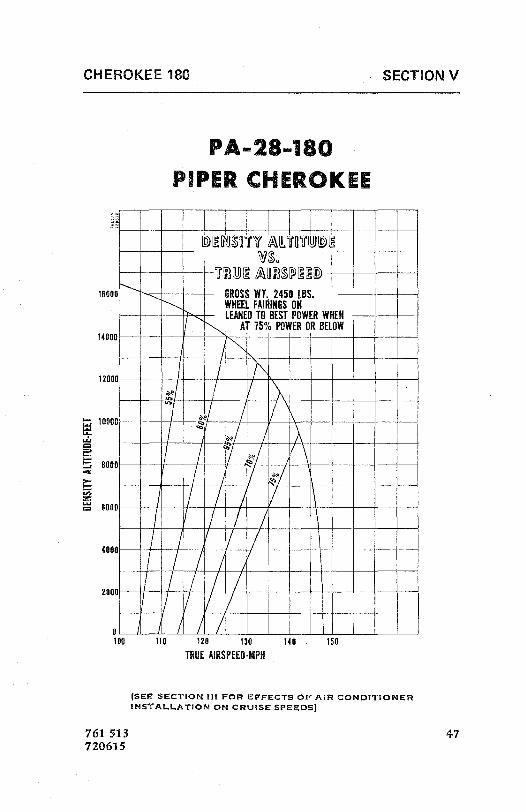
CHEROKEE 180 SECTION V
PA-28-180PIPER CHEROKEE
VS.TUUUABBSPUID
16000 --- GROSSWT.2450LBS. -WHEELFAIIIINGSON- - LEANEDTOBESTPOWERWHEN
14066T 75% POWER0 BELOW
12008
8080-
en CCCC
¾000
If0 110 120 130 140 150
TRUEAIRSPEED-MPH
(SEE SECTION III FOR EFFECTS OF AIR CONDITIONERINSTALLATION ON CRUISE SPEEDS)
761 513 47720615

SECTION V CHEROKEE 180
PA-28-180PIPER CHEROKEE
GROSSWT.2450LBS.WHEELFAIRINGSONESTPOWFR
12000
10000
8000
0000
2000 2100 2200 2300 2430 2500 2000 2700
ENGINERPM
761 513720615

SECTION V CHEROKEE 180
PA-28-180
PIPER CHEROKEE
POWEROFF FLAPS40° PAVEDLEVELDRYRUNWAYNOWINDMAXIMUMBRAKINGSHORTFIELDEFFORT
GROSSWEIGHT2450LBS.
7000
6000
5000
4000
t- 3000 -
2000
1000
410 800 800 1000 1200 1400
LANDINGDISTANCE-FEET
761 513 49720615

CHEROKEE 180 SECTION V
NOTES
50 761513720615

SECTION VI
GENERAL MAINTENANCE
Landing Gear Service . . . . . . . . . . . . . . . . . . . . 51
BrakeService.......... . .. . ....... 53
TireInflation......... ... . .. . ........ 53
Care of Windshield and Windows . . . . . . . . . . . . . . . . . 54
BatteryService .......... . ... .. ....... 54
Fuel and Oil Requirements . . . . . . . . . . . . . . . . . . . 55
FuelSystem ........ ......... 55
CareofAirFilter ......... . . ......... 55
Leveling and Rigging . . . . . . . . . . . . . . . . . . . . 56
SerialNumberPlate .......... . .......... 57

CHEROKEE 180 SECTION VI
SECTION VI
GENERAL MAINTENANCE
This section of the Cherokee Handbook contains informationwhich pertains to minor maintenance of the airplane. For furthermaintenance assistance refer to the Service Manual for this airplane.
Any complex repairs or modification should be accomplished by aPiper Certified Service Center or equivalent.
LANDING GEAR SERVICE
The main wheels are Cleveland Aircraft Products, Modelf 40-86,with Cleveland single disk hydraulic brake assemblies, ModelA30-55.The nose wheel is a Cleveland Aircraft Products, Model 40-76B. Allwheels use a 6.00 x 6, four ply rating, Type III tire with tube.
Main wheels are easily removed by taking off the hub cap, axle nut,and the two bolts holding the brake segment in place, after which thewheel slips easily from the axle.
Tires are demounted from the wheels by deflating the tire,removing the three through-bolts, and separating the wheel halves.
Landing gear oleo struts should be checked for proper strutexposures and fluid leaks. The required extensions for the strut whenunder normal static load (empty weight of airplane plus full fuel andoil) is 3.25 inches for the nose gear and 4.50 inches f'or the main gear.Should the strut exposure be below that required, it should bedetermined whether air or oil is required by first raising the airplane onjacks. Depress the valve core to allow air to escape from the struthousing chamber. Remove the filler plug and slowly raise the strut tofull compression. If the strut has sufficient fluid it will be visible up tothe bottom of the filler plug hole and will then only require properinflation.
761 513 51720615

SECTION VI CHEROKEE 180
Should fluid be below the bottom of the filler plug hole, oil shouldbe added. Replace the plug with valve core removed, attach a clearplastic hose to the valve strut of the filler plug and submerge the other
end in a container of hydraulic fluid (MIL-H-5606). Fully compress andextend the strut several times thus drawing fluid from the container andexpelling air from the strut chamber. To allow the fluid to enter thebottom chamber of the main gear strut housing, the torque linkassembly must be disconnected to let the strut be extended a minimumof 10 inches. (The nose gear torque links need not be disconnected.) Donot allow the strut to extend more than 12 inches. When air bubblescease to flow through the hose, compress the strut fully and againcheck fluid level. Reinstall the valve core and filler plug, and the maingear torque links, if disconnected.
With fluid in the strut housing at the correct level, attach a strutpump to the air valve and with the airplane on the ground, inflate theoleo strut to the correct height.
In jacking the Cherokee for landing gear or other service, a jack kit(available through Piper Dealers or Distributors) should be used. Thiskit consists of two hydraulic jacksand a tail stand. At least 250 poundsof ballast should be placed on the base of the tail stand before the
airplane is jacked up. The hydraulic jacks should be placed under thejack points on the bottom of the wing and the airplane jackedup until
the tail skid is at the right height to attach the tail stand. Afterattaching the tail stand and adding the ballast, the jacking may becontinued until the aircraft is at the height desired.
The steering arms from the rudder pedals to the nose wheel areadjusted at the rudder pedals or at the nose wheel by turning in or outthe threaded rod end bearings. Adjustment is normally accomplished atthe forward end of the rods and should be done in such a way that thenose wheel is in line with the fore and aft axis of the plane when the
rudder pedals and rudder are centered. Alignment of the nose wheel canbe checked by pushing the airplane back and forth with the ruddercentered to determine that the plane follows a perfectly straight line.The turning are of the nose wheel is 22 degrees in either direction and
factory adjusted at stops on the bottom of the forging. The turningradius of the nose wheel is 17 feet.
52 761513720615

CHEROKEE 180 SECTION VI
The steering arm stops should be carefully adjusted so that thenose wheel reaches its full travel just after the rudder hits its stops. Thisguarantees that the rudder will be allowed to move through its fulltravel.
BRAKE SERVICE
The brake system is filled with MIL-H-5606 (Petroleum base)hydraulic brake fluid. This should be checked at every 50 hourinspection and replenished when necessary by filling the brake reservoiron the upper left front side of the firewall to the indicated level. If the
system as a whole has to be refilled with fluid it should be done fromthe brake end of the system by filling with fluid under pressure. Thiswill eliminate air from the system as it is being filled.
No adjustment of brake clearances is necessary on the Cherokeebrakes. If after extended service the brake blocks become wornexcessively, they are easily replaced with new segments.
TIRE INFLATION
For maximum service from the tires on the Cherokee, keep thetires inflated to the proper pressure of 24 pounds for all three wheels.Interchange the tires on the main wheels if necessary to produce evenwear. All wheels and tires are balanced before original installation, andthe relationship of the tire, tube, and wheel should be maintained if atall possible. Unbalanced wheels can cause extreme vibration ontake-off. In the installation of new components it may be necessary torebalance the wheel with the tire mounted.
761 513 53720615

SECTION VI CHEROKEE 180
CARE OF WINDSHIELD AND WINDOWS
A certain amount of care is needed to keep the plexiglas windows
clean and unmarred. The following procedure is recommended:1. Flush with clean water and dislodge excess dirt, mud, etc. with
your hand.2. Wash with mild soap and water or Piper Plastic Cleaner. Use a
soft cloth or sponge. Do not rub.
3. Remove oil, grease or sealing compounds with a soft cloth andkerosene.
4. After cleaning, apply a thin coat of hard polishing wax. Rublightly with a soft cloth.
5. A severe scratch or may may be removed by using jeweler'srouge to rub out the scratch, smoothing, and then applying wax.
BATTERY SERVICE
Access for service or inspection of the battery is obtained throughthe removal of the panel at the right rear side of the baggagecompartment. The stainless steel box has a plastic drain tube which isnormally closed off with a clamp and which should be openedoccasionally to drain off any accumulation of liquid. The batteryshould be checked for proper fluid level, but must not be filled abovethe baffle plates. Use only water - no acid. A hydrometer check shouldbe performed to determine the percent of charge present in the battery.
If the battery is not up to charge, recharge starting at a 4 ampererate and finishing with a 2 ampere rate. Quick charges are notrecommended.
54 761513720615

CHEROKEE 180 SECTION VI
FUEL AND OIL REQUIREMENTS
Aviation Grade 100/130 Octane (minimum) fuel must be used inthe Cherokee. Because the use of lower grades can cause serious damagein a very short period of time, the engine warranty is invalidated bysuch use.
The oil capacity of the Lycoming O-360-A4A is 8 quarts, and theminimum safe quantity is 2 quarts. It is recommended that the oil andoil filter be changed every 50 hours, or sooner under unfavorableconditions. The following grades are recommended for the specifictemperatures:
Temperatures above 60°F S.A.E. 50Temperatures between 30° and
90°FS.A.E. 40
Temperatures between 0° and 70°F S.A.E. 30Temperatures below 10°F S.A.E. 20
FUEL SYSTEM
The fuel screen in the strainer will require cleaning every 50 hourinspection. The strainer, located ahead of the firewall, is accessible forcleaning by removal of the lower cowl. When the strainer is reassembledafter cleaning, a small amount of grease applied to the gasket willfacilitate assembly.
CARE OF AIR FILTER
The carburetor air filter must be cleaned at least once every fiftyhours. Under extremely adverse conditions of operation it may benecessary to clean the filter daily. Extra filters are inexpensive and aspare should be kept on hand and used as a rapid replacement.
The filter manufacturer recommends that the filter be tappedgently to remove dirt particles. Do not blow out with compressed air.
761 513 55720615

SECTION VI CHEROKEE 180
LEVELING AND RIGGING
Leveling the Cherokee "F" for purposes of weighing or rigging isaccomplished as follows:
1. Partially withdraw two machine screws located immediatelybelow the left front side window. These screws are leveling points, andthe airplane is longitudinally level when a level placed on the heads ofthese screws indicates level.
2. To put the airplane in a longitudinally level position on scales,first block the main gear oleos in the fully extended position, then
deflate the nose wheel tire until the proper attitude is obtained. Forrigging only, the airplane may be placed on jacksfor leveling.
3. To level the airplane laterally, place a level across the baggagecompartment floor along the rear bulkhead.
Rigging: Although the fixed flight surfaces on the Cherokeecannot be adjusted for rigging purposes, it may be necessary uponoccasion to check the position of these surfaces. The movable surfacesall have adjustable stops, as well as adjustable turnbuckles on the cablesor push-pull tubes, so that their range of travel can be altered. Thepositions and angular travels of the various surfaces are as follows:
1. Wings: 7° dihedral, 2° washout.2. Stabilator Travel: 14 ° up, 2° down, tolerance
±1°.
3. Fin should be vertical and in line with center of fuselage.4. Aileron Travel: 30°
up,15°
down, tolerance±2°.
5. Flap Travel: 10°, 25°, 40°, tolerance ±2°.
6. Rudder Travel: 27° right and left, tolerance ±2°.
7. Stabilator Tab Travel: 3°up,
12° down, tolerance ±1°.
Cable tensions for the various controls are as follows:Rudder: 40 ±5 # Stabilator: 40 ±5 2Ailerons: 40 ±5 # Stabilator Trim: 10 ±1#Flaps: Approx. 10
56 761 513720615

CHEROKEE 180 SECTION VI
For extreme cases of wing heaviness, the flap on the wing heavyside may be adjusted down from the zero position as desired.
The service manual should be consulted for the proper method ofadjusting surface travels.
SERIAL NUMBER PLATE
The serial number plate is located near the stabilator on the leftside of the airplane. Refer to this number for service or warrantymatters.
761 513 57720615

SECTION VI CHEROKEE 180
NOTES
58 761513720615

INDEX
SECTION I PageSpecifications: ........................... 1
Performance ............. . .......... 1Weights ............... ............ 2PowerPlant .......................... 2FuelandOil .......................... 2Baggage................ ............ 2Dimensions........................... 3LandingGear ........... ............. 3
SECTION IIDesignInformation: ........... ........... 5
EngineandPropeller ..................... 5Structures ........................... 5LandingGear ............. ........... 6ControlSystem .......... . ......... 7FuelSystem .......... . ........... 7ElectricalSystem .......... ........... 9Heating and Ventilating System . . . . . . . . . . . . . . . 13CabinFeatures........... ........... 13OptionalEquipment ..................... 16
SECTION IIIOperating Instructions: . . . . . . . . . . . . . . . . . . . . . . 19
Preflight ............................ 19StartingEngine ........... ........... 20Warm-Up and Ground Check . . . . , , , . . . . . . . . . 22Take-Off
............... ........... 23Climb .............................. 23Stalls ................. ........... 24Cruising........... .......... 24ApproachandLanding .................... 25StoppingEngine........... ............ 26

INDEX (cont)
SECTION III (cont) PageEnginePowerLoss ...................... 26Mooring ............................ 27WeightandBalance ...................... 27OperatingTips......................... 27OptionalEquipment ..................... 30
SECTION IVEmergency Procedures: . . . . . . . . . . . . . . . . . . . . . . 33
Introduction .......................... 33GroundOperations ...................... 33Take-Off
............................ 34InFlight ............................ 35
PowerOffLanding.................... 36Fire ............................ 37LossofOilPressure ................... 37Loss of Fuel Pressure . . . . . . . . . . . . . . . . . . 38High Oil Temperature . . . . . . . . . . . . . . . . . . 38AlternatorFailure .................... 38ÈngineRoughness .................... 39Spins............................ 40OpenDoor ........................ 40
SECTION VPerformanceCharts: ........................ 43
Take-Off Distance vs Density Altitude . . . . . . . . . . . 43Altitude Conversion Chart . . . . . . . . . . . . . . . . . . 44Rate of Climb vs Density Altitude . . . . . . . . . . . . . 45Range vs Density Altitude . . . . . . . . . . . . . . . . . . 46True Airspeed vs Density Altitude . . . . . . . . . . . . . 47RPM vs Density Altitude . . . . . . . . . . . . . . . . . . . 48Landing Distance vs Density Altitude . . . . . . . . . . . . 49

INDEX (cont)
SECTION VI PageGeneral Maintenance: . . . . . . . . . . . . . . . . . . . . 51
Landing Gear Service . . . . . . . . . . . . . . . . . . 51BrakeService .......... ............. 53Tireinflation .......... .. ......... 53Care of Windshield and Windows . . . . . . . . . . . . . . 54Battery Service . . . . . . . . . . . . . . . . . . . . 54FuelandOilRequirements.. .. ... .. . . . .. .. .. 55FuelSystem ........... ............ 55CareofAirFilter ......... . ........ 55Leveling and Rigging . . . . . . . . . . . . . . . . . 56SerialNumberPlate...................... 57


