owner’s manual - pelican water
TRANSCRIPT

425 Clair Rd. W, Guelph, Ontario, Canada N1L 1R1t. (+1) 519.763.1032 • tf. (+1) 800.265.7246 (US and Canada only)t. (+31) 73 747 0144 (Europe only) • f. (+1) 519.763.5069e-mail: [email protected]
Models:H, K
Plus Models:H+, K+
PRO Models:PRO10, PRO20, PRO30, PRO50
Owner’s Manual
Powered by
PRO10, PRO20, PRO30 Tested and Certified by NSF International against CSA B483.1 and NSF/ANSI 55 forDisinfection Performance, Class A
602936_RevAJ
2
Congratulations on the purchase of your ultraviolet (UV) water disinfection system! This system uses the most advanced UV technology on the market and is designed to provide you with years of trouble free operation with minimal maintenance required to protect your drinking water from microbiological contaminants.To ensure ongoing disinfection of your water, UV lamps need to be replaced annually with VIQUA factory-supplied replacements. VIQUA lamps are the result of extensive development resulting in a highly efficient disinfection platform with extremely stable UV output over the entire 18000 hour lifetime. Its success has led to a proliferation of non-genuine copies in the market.
The UV lamp is the heart of the disinfection system, and there should be no compromise when it's time for a replacement.
Why should you insist on genuine factory supplied VIQUA replacement lamps?
• Use of widely available, non-genuine, replacement lamps has been shown to damage the control module of VIQUA UV disinfection equipment.
• An increasing number of calls to VIQUA Technical Support are connected with non-genuine lamps being used (unknowingly) as replacements.
• Damage arising from the use of non-genuine lamps poses a safety risk and is not covered by equipment warranty.
• Unless the UV equipment is equipped with a UV sensor (monitor), it is not possible to verify the UV (invisible) output of replacement lamps.
• Similar appearance to the original lamp and the presence of (visible) blue light does not mean equivalent disinfection performance.
• VIQUA replacement lamps undergo rigorous performance testing and strict quality control processes to ensure that the safety and performance certifications of the original equipment are not compromised.
So, you can see that it's simply not worth the risk! Insist on genuine VIQUA replacement lamps.

Safety Information
3
Section 1 Safety Information
These are the original instructions.Please read this entire manual before operating this equipment. Pay attention to all danger, warning, and caution statements in this manual. Failure to do so could result in serious personal injury or damage to the equipment.Make sure that the protection provided by this equipment is not impaired. DO NOT use or install this equipment in any manner other than that specified in the installation manual.
1.1 Potential Hazards:Read all labels and tags attached to the system. Personal injury or damage to the system could occur if not observed.
1.2 Safety Precautions:
Waste electrical and electronic equipment (WEEE). This symbol indicates that you should not discard wasted electrical or electronic equipment (WEEE) in the trash. For proper disposal, contact your local recycling/reuse or hazardous waste center.
This symbol indicates not to store any combustible or flammable material close to the system.
This symbol indicates there is Mercury present. This symbol indicates that the contents of the transport package are fragile and the package should be handled with care.
This is the safety alert symbol. Obey all safety messages that follow this symbol to avoid potential injury. When on the equipment, refer to the Operational and Maintenance manual for additional safety information.
This symbol indicates safety glasses with side protection is required for protection against UV exposure.
This symbol indicates a risk of electrical shock and/or electrocution exists. This symbol indicates gloves must be worn.
This symbol indicates the marked equipment may contain a component that can eject forcibly. Obey all procedures to safely depressurize.
This symbol indicates safety boots must be worn.
This symbol indicates the system is under pressure. This symbol indicates the operator must read all available documentation to perform required procedures.
This symbol indicates there is a potential UV hazard. Proper protection must be worn. This symbol indicates the plumber must use copper piping.
This symbol indicates the marked item could be hot and should not be touched without care.
This symbol indicates that the system should only be connected to a properly grounded, grounding-type controller receptacle that is protected by a Ground Fault Circuit Interrupter (GFCI).
This symbol indicates there is a potential for VERY hot water when flow is started.
D A N G E RFailure to follow these instructions will result in serious injury or death. • Electric Shock: To avoid possible electric shock, special care should be taken since water is present near the electrical equipment. Unless a
situation is encountered that is explicitly addressed by the provided maintenance and troubleshooting sections, DO NOT attempt repairs yourself, refer to an authorized service facility.
• GROUNDING: This product must be grounded. If it should malfunction or breakdown, grounding provides a path of least resistance for electric current to reduce the risk of electrical shock. This system is equipped with a cord having an equipment-grounding conductor and a grounding plug. The plug must be plugged into an appropriate outlet that is properly installed and grounded in accordance with all local codes and ordinances. Improper connection of the equipment-grounding conductor can result in a risk of electrocution. Check with a qualified electrician or service personnel if you are in doubt as to whether the outlet is properly grounded. DO NOT modify the plug provided with this system – if it does not fit in the outlet, have a proper outlet installed by a qualified electrician. DO NOT use any type of adapter with this system.
• GROUND FAULT CIRCUIT INTERRUPTER PROTECTION: To comply with the National Electrical Code (NFPA 70) and to provide additional protection from the risk of electric shock, this system should only be connected to a properly grounded, grounding-type controller receptacle that is protected by a Ground Fault Circuit Interrupter (GFCI) or to a residual current device (RCD) having a rated residual operating current not exceeding 30 mA. Inspect operation of GFCI as per manufacturer’s suggested maintenance schedule.
• DO NOT operate the disinfection system if it has a damaged cord or plug, if it is malfunctioning or if it has been dropped or damaged in any manner. • DO NOT use this disinfection system for other than intended use (potable water applications). The use of attachments not recommended or sold by
the manufacturer / distributor may cause an unsafe condition. • DO NOT install this disinfection system where it will be exposed to the weather or to temperatures below freezing. • DO NOT store this disinfection system where it will be exposed to the weather. • DO NOT store this disinfection system where it will be exposed to temperatures below freezing unless all water has been drained from it and the
water supply has been disconnected.
Hg
UVCu
Safety Information
4
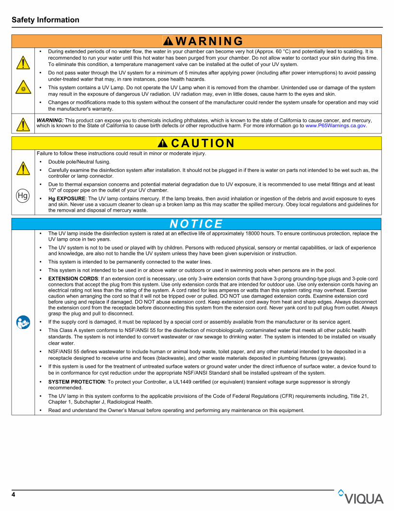
W A R N I N G • During extended periods of no water flow, the water in your chamber can become very hot (Approx. 60 °C) and potentially lead to scalding. It is
recommended to run your water until this hot water has been purged from your chamber. Do not allow water to contact your skin during this time. To eliminate this condition, a temperature management valve can be installed at the outlet of your UV system.
• Do not pass water through the UV system for a minimum of 5 minutes after applying power (including after power interruptions) to avoid passing under-treated water that may, in rare instances, pose health hazards.
• This system contains a UV Lamp. Do not operate the UV Lamp when it is removed from the chamber. Unintended use or damage of the system may result in the exposure of dangerous UV radiation. UV radiation may, even in little doses, cause harm to the eyes and skin.
• Changes or modifications made to this system without the consent of the manufacturer could render the system unsafe for operation and may void the manufacturer's warranty.
WARNING: This product can expose you to chemicals including phthalates, which is known to the state of California to cause cancer, and mercury, which is known to the State of California to cause birth defects or other reproductive harm. For more information go to www.P65Warnings.ca.gov.
C A U T I O NFailure to follow these instructions could result in minor or moderate injury. • Double pole/Neutral fusing. • Carefully examine the disinfection system after installation. It should not be plugged in if there is water on parts not intended to be wet such as, the
controller or lamp connector. • Due to thermal expansion concerns and potential material degradation due to UV exposure, it is recommended to use metal fittings and at least
10" of copper pipe on the outlet of your UV chamber. • Hg EXPOSURE: The UV lamp contains mercury. If the lamp breaks, then avoid inhalation or ingestion of the debris and avoid exposure to eyes
and skin. Never use a vacuum cleaner to clean up a broken lamp as this may scatter the spilled mercury. Obey local regulations and guidelines for the removal and disposal of mercury waste.
N O T I C E • The UV lamp inside the disinfection system is rated at an effective life of approximately 18000 hours. To ensure continuous protection, replace the
UV lamp once in two years. • The UV system is not to be used or played with by children. Persons with reduced physical, sensory or mental capabilities, or lack of experience
and knowledge, are also not to handle the UV system unless they have been given supervision or instruction. • This system is intended to be permanently connected to the water lines. • This system is not intended to be used in or above water or outdoors or used in swimming pools when persons are in the pool. • EXTENSION CORDS: If an extension cord is necessary, use only 3-wire extension cords that have 3-prong grounding-type plugs and 3-pole cord
connectors that accept the plug from this system. Use only extension cords that are intended for outdoor use. Use only extension cords having an electrical rating not less than the rating of the system. A cord rated for less amperes or watts than this system rating may overheat. Exercise caution when arranging the cord so that it will not be tripped over or pulled. DO NOT use damaged extension cords. Examine extension cord before using and replace if damaged. DO NOT abuse extension cord. Keep extension cord away from heat and sharp edges. Always disconnect the extension cord from the receptacle before disconnecting this system from the extension cord. Never yank cord to pull plug from outlet. Always grasp the plug and pull to disconnect.
• If the supply cord is damaged, it must be replaced by a special cord or assembly available from the manufacturer or its service agent. • This Class A system conforms to NSF/ANSI 55 for the disinfection of microbiologically contaminated water that meets all other public health
standards. The system is not intended to convert wastewater or raw sewage to drinking water. The system is intended to be installed on visually clear water.
• NSF/ANSI 55 defines wastewater to include human or animal body waste, toilet paper, and any other material intended to be deposited in a receptacle designed to receive urine and feces (blackwaste), and other waste materials deposited in plumbing fixtures (greywaste).
• If this system is used for the treatment of untreated surface waters or ground water under the direct influence of surface water, a device found to be in conformance for cyst reduction under the appropriate NSF/ANSI Standard shall be installed upstream of the system.
• SYSTEM PROTECTION: To protect your Controller, a UL1449 certified (or equivalent) transient voltage surge suppressor is strongly recommended.
• The UV lamp in this system conforms to the applicable provisions of the Code of Federal Regulations (CFR) requirements including, Title 21, Chapter 1, Subchapter J, Radiological Health.
• Read and understand the Owner’s Manual before operating and performing any maintenance on this equipment.
UV
Hg

General Information
5
1.3 Water ChemistryWater quality is extremely important for the optimum performance of your UV system. The following levels are recommended for installation:
* Where total hardness is less than 7 gpg, the UV unit should operate efficiently provided the quartz sleeve is cleaned periodically. If total hardness exceeds 7 gpg, the water should be softened. If your water chemistry contains levels in excess of those mentioned above, proper pre-treatment is recommended to correct these water problems prior to the installation of your UV disinfection system. These water quality parameters can be tested by your local dealer, or by most private analytical laboratories. Proper pre-treatment is essential for the UV disinfection system to operate as intended.
Section 2 General Information
Water Quality and Minerals Level
Iron < 0.3 ppm (0.3 mg/L)Hardness* < 7 gpg (120 mg/L)Turbidity < 1 NTUManganese < 0.05 ppm (0.05 mg/L)Tannins < 0.1 ppm (0.1 mg/L)UV Transmittance > 75% (call factory for recommendations on applications where UVT < 75%)
Figure 1 System Components
1
2
3
4
6
7
89
11
12
13
14
7
10
5

General Information
6
Item Description Part Number UV Systems
1 Controller
650709-003 PRO10
650709-006 PRO20
650709-009 PRO30
660020-R PRO50
650709-005 H+
660019-R K+
650709-004 H
660018-R K
2 Top Bolt and Wireform 602916 & 602896 Used for all systems
3 Lamp
602854 PRO10
602855 PRO20, H+, H
602856 PRO30/50, K+, K
4 Sleeve
602974 PRO10
602975 PRO20, H+, H
602976 PRO30/50, K+, K
5 CoolTouch Fan 650630 Used for all systems
6 Chamber - Used for all systems
7 O-ring 002233 Used for all systems
8 Bottom bolt (includes screw) 603053 Used for all systems
9 Sleeve Removal Tool 602988 Used for all systems
10 Flow Meter Sensor (PRO models only)
410982R-10 PRO10
410982R-20 PRO20
410982R-30 PRO30
11 Sensor 650580 PRO and Plus models
12 Plug - Basic models
13 Power cord602636 110V - Used for all systems
602637 220V - Used for all systems
14 Lamp cord - Used for all systems

General Information
7
2.1 Dimensions and Layout
Figure 2 System - Dimension and Layout
Item Description Function
1 Sample Valve Allows for sampling of raw water.
2 Shut-off Valve Allows for ease of maintenance of pre-treatment equipment.
3 Pre-Treatment Pre-treatment allows the UV system to operate effectively. The water should meet certain water quality parameters before entering UV System.
4 Bypass shut-off valve: Bypass line and valve are optional. Intended to provide emergency water supply in the event that the UV system is unavailable.
5 Shut-off valve Required to allow maintenance of UV system.
6 Solenoid valve
Allows water supply to be shut-off when proper disinfection cannot be assured.Note: If the ground from your electrical panel is tied to your copper water lines, and you are using a Plastic Body solenoid valve, installation of an approved ground strap is required. This ground strap will maintain continuity between the lines that have been cut to install the solenoid. Check your local electrical code for the correct clamp and cable size.
7 Sample valve Allows for sampling of water entering UV chamber; necessary in order to confirm water being treated is of adequate quality.
8 Plug A stopper provided and installed on Basic models.
9 Sensor Monitors UV output to ensure proper dose (UV exposure) is being provided.
10 UV chamber Provides disinfection of the water. MUST BE INSTALLED VERTICALLY.
11 CoolTouch™ fan Removes excess heat from water in chamber during periods without water flow.
12 Sample valve Allows for sampling of water immediately following UV treatment; necessary in order to confirm proper operation of UV system.
13 Shut-off valve Allows maintenance of UV system.
INLET
OUTLET
Clearancefor lampremoval
72” (183cm)
1”
A B
C
L
L
S
D
Ø
6
1
16
2
3
5
4
1311
12
7
15
98
10”
10
14
General Information
8
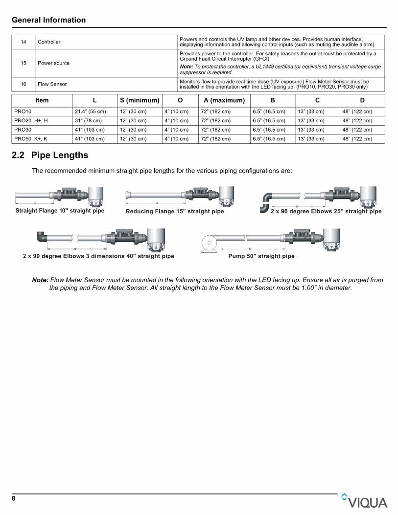
2.2 Pipe Lengths
The recommended minimum straight pipe lengths for the various piping configurations are:
Note: Flow Meter Sensor must be mounted in the following orientation with the LED facing up. Ensure all air is purged from the piping and Flow Meter Sensor. All straight length to the Flow Meter Sensor must be 1.00" in diameter.
14 Controller Powers and controls the UV lamp and other devices. Provides human interface, displaying information and allowing control inputs (such as muting the audible alarm).
15 Power source
Provides power to the controller. For safety reasons the outlet must be protected by a Ground Fault Circuit Interrupter (GFCI).Note: To protect the controller, a UL1449 certified (or equivalent) transient voltage surge suppressor is required.
16 Flow Sensor Monitors flow to provide real time dose (UV exposure) Flow Meter Sensor must be installed in this orientation with the LED facing up. (PRO10, PRO20, PRO30 only)
Item L S (minimum) O A (maximum) B C D
PRO10 21.4” (55 cm) 12” (30 cm) 4” (10 cm) 72” (182 cm) 6.5” (16.5 cm) 13” (33 cm) 48” (122 cm)
PRO20, H+, H 31" (78 cm) 12” (30 cm) 4” (10 cm) 72” (182 cm) 6.5” (16.5 cm) 13” (33 cm) 48” (122 cm)
PRO30 41" (103 cm) 12” (30 cm) 4” (10 cm) 72” (182 cm) 6.5” (16.5 cm) 13” (33 cm) 48” (122 cm)
PRO50, K+, K 41" (103 cm) 12” (30 cm) 4” (10 cm) 72” (182 cm) 6.5” (16.5 cm) 13” (33 cm) 48” (122 cm)
Straight Flange 10" straight pipe Reducing Flange 15" straight pipe 2 x 90 degree Elbows 25" straight pipe
2 x 90 degree Elbows 3 dimensions 40" straight pipe Pump 50" straight pipe

Installation
9
Section 3 Installation
3.1 Installing UV System
Prerequisites: • Determine appropriate indoor location of the controller and chamber, refer to Section 2.1.• Make sure that the controller is installed higher than the chamber and away from all water sources.• Ensure adequate clearance above chamber to allow for removal of the lamp and sleeve.• Make sure to turn off the main water supply.• Make all necessary plumbing connections refer to Section 2.1.
Procedure:
C A U T I O NElectronic controller must be connected to a Ground Fault Protected Circuit (GFCI) receptacle.
1
• Install the UV Chamber vertically with the following spacing on the wall using screws.• PRO10: 18.5"• H, PRO20: 27.5"• K, PRO30/50: 37.5"Note: Ensure chamber is installed with green arrows pointing upwards.
22
• Connect Flow Meter Sensor (PRO10,20,30 models only) to chamber using 1¼” unions supplied.Note: LED must face up. Ensure proper length of straight pipe 1.0" Diameter at inlet side of Flow Meter Sensor and use a 1¼” to 1" Reducing Coupler (not supplied).
3
• Install the sensor to the UV system (for PRO models only). Note: DO NOT use wrench to tighten the sensor.
4
21
• Connect the sleeve bolt at the bottom of the sleeve assembly. Ensure sleeve bolt is rotated full 1/4 turn until positive stop.
5
• Insert sleeve with arrow pointing up. Note: DO NOT rotate sleeve and touch glass with bare hands.
6
• Wet O-ring with water then place over top end of sleeve.
7
2
1
• Connect the sleeve bolt to the top of the sleeve assembly. Ensure sleeve bolt is rotated full 1/4 turn until positive stop.
8
1 2
• Remove the sleeve bolt at the bottom of the sleeve assembly.
Installation
10
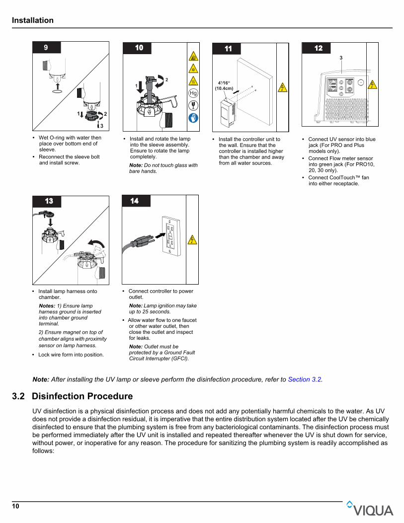
Note: After installing the UV lamp or sleeve perform the disinfection procedure, refer to Section 3.2.
3.2 Disinfection Procedure
UV disinfection is a physical disinfection process and does not add any potentially harmful chemicals to the water. As UV does not provide a disinfection residual, it is imperative that the entire distribution system located after the UV be chemically disinfected to ensure that the plumbing system is free from any bacteriological contaminants. The disinfection process must be performed immediately after the UV unit is installed and repeated thereafter whenever the UV is shut down for service, without power, or inoperative for any reason. The procedure for sanitizing the plumbing system is readily accomplished as follows:
9
3
21
• Wet O-ring with water then place over bottom end of sleeve.
• Reconnect the sleeve bolt and install screw.
1010
21
Hg
UV
• Install and rotate the lamp into the sleeve assembly. Ensure to rotate the lamp completely.Note: Do not touch glass with bare hands.
1111
4¹⁄16“(10.4cm)
• Install the controller unit to the wall. Ensure that the controller is installed higher than the chamber and away from all water sources.
12123
• Connect UV sensor into blue jack (For PRO and Plus models only).
• Connect Flow meter sensor into green jack (For PRO10, 20, 30 only).
• Connect CoolTouch™ fan into either receptacle.
1313
• Install lamp harness onto chamber.Notes: 1) Ensure lamp harness ground is inserted into chamber ground terminal.
2) Ensure magnet on top of chamber aligns with proximity sensor on lamp harness.
• Lock wire form into position.
1414
• Connect controller to power outlet. Note: Lamp ignition may take up to 25 seconds.
• Allow water flow to one faucet or other water outlet, then close the outlet and inspect for leaks.Note: Outlet must be protected by a Ground Fault Circuit Interrupter (GFCI).

Installation
11
Procedure:
1
2
3
1
• Disconnect the controller then disconnect the UV sensor from blue jack.
• Reconnect the controller with out UV sensor.
2
2
1
2
2
2
• Shut off the water supply.• Open an upstream faucet to
release line pressure
3
• Press the pressure button to release the pressure from the cartridges.
4
• Remove filter housing(s) using sump wrench.
5 Household 5.25% Bleach SolutionBLEACH
x221
• Remove cartridge(s) and pour 2 cups of household bleach solution into the filter housing(s).Note: DO NOT use Hydrogen Peroxide.
6
• Connect only the filter housing(s) to the unit.
7
• Open each faucets and turn on water supply.
• Allow water to fill the chamber.
8
0
30
1545
30 mins
• Turn on the cold water supply followed by hot water (if available) until you smell the bleach.
• Close all faucets and allow bleach to settle in the water lines for 30 minutes.
9
• With all faucets closed, remove filter housing(s) using sump wrench.
10101 2
• Reinstall the cartridge(s) into filter housing(s) and connect to the unit.
• Flush all water outlets until bleach can no longer be smelled (at least 5 minutes).
11
• Press the pressure button to purge air and to complete the disinfection procedure.
1212
2
3
1
• Disconnect the controller then connect the UV sensor from blue jack.
• Reconnect the controller.

Maintenance
12
Section 4 Maintenance
4.1 Replacing UV Lamp
UV lamp replacement is a quick and simple procedure requiring no special tools. The UV lamp must be replaced after 18000 hours of continuous operation (approximately two years) in order to ensure adequate disinfection.
Procedure:
W A R N I N G • Always disconnect power before performing any work on the disinfection system.
• Always shut-off water flow and release water pressure before servicing.
• Regularly inspect your disinfection system to ensure that the power indicators are on and no alarms are present.
• Replace the UV lamp biennially to ensure maximum disinfection.
• Always drain the chamber when closing a seasonal home or leaving the unit in an area subject to freezing temperatures.
N O T I C EDo not use water during replacement of UV lamp.
1
1 1
2
• Close all faucets and water supply.
• Press the pressure button to release the pressure from the cartridges.
2
0
30
1545
10 mins
• Disconnect main power source and allow the unit to power down for 10 minutes.
3
• Drain the water from the UV system.
• Close the water inlet after the water is drained.
4
• Pinch wire form to release the lamp connector.
5
• Remove the lamp connector.
6
Hg
UV
21
• Rotate and remove the UV lamp from the sleeve.
7
21
Hg
UV
• Install and rotate the lamp into the sleeve assembly. Ensure to rotate the lamp completely.Note: Do not touch glass with bare hands.
8
• Reinstall the lamp connector.

Maintenance
13
Note: After replacing the UV lamp perform the disinfection procedure, refer to Section 3.2.
4.2 Cleaning and Replacing Sleeve
Note: Minerals in the water slowly form a coating on the lamp sleeve. This coating must be removed because it reduces the amount of UV light reaching the water, thereby reducing disinfection performance. If the sleeve can not be cleaned, it must be replaced.
Prerequisites:
• Shut off water supply and drain all lines.
• Remove the UV lamp. Refer to Section 4.1.
Procedure:
9
1
2
Commercial Scale Remover
• Remove the UV sensor from the unit.
• Submerge the end of the sensor in the commercial scale remover for 30 minutes.
• Clean the sensor with a cotton swab and spray with water.
• For Basic model skip to step 10.
1010
• Lock the wire form into position.
11
• Restore Power.• Press and hold the “New
Lamp” button for 5 seconds till you hear a beep.Note: Lamp ignition may take up to 25 seconds.
1212
• Turn on the water supply.
1
21
• Remove the sleeve bolt from top of the sleeve assembly.
2
1
2 3
• Remove screw from the sleeve bolt.
• Remove the sleeve bolt at the bottom of the sleeve assembly.
3
• Insert the sleeve removal tool into the bottom of the sleeve.
44
• Pry sleeve upward until it come loose.
• Place bucket under UV chamber, water will escape.

Maintenance
14
Note: After replacing the UV lamp or sleeve perform the disinfection procedure, refer to Section 3.2.
5
• Remove the sleeve.
6
• Remove O-ring from top of the sleeve.
• Remove O-ring from bottom of the chamber (it may fall during sleeve removal process).
7
Mild Acid
• Clean the sleeve with a cloth soaked in CLR, vinegar or some other mild acid and then rinse with water.Note: If sleeve cannot be cleaned completely or it is scratched or cracked, then replace the sleeve.
8
3
1
2
• Connect the sleeve bolt at the bottom of the sleeve assembly.
9
• Reinstall the sleeve with arrow pointing up.Note: DO NOT rotate sleeve and touch glass with bare hands.
1010
• Reinstall the new lubricated O-rings over the top end of the sleeve.
1111
2
1
• Connect the sleeve bolt to the top of the sleeve assembly.
1212
1 2
• Remove the sleeve bolt at the bottom of the sleeve assembly.
1313
• Reinstall the O-ring at the bottom of the sleeve.
1414
3
21
• Connect the sleeve bolt at the bottom.
• When service is complete, assemble the prerequisites in the reverse order of disassembly.
Maintenance
15
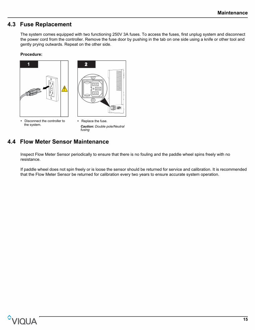
4.3 Fuse Replacement
The system comes equipped with two functioning 250V 3A fuses. To access the fuses, first unplug system and disconnect the power cord from the controller. Remove the fuse door by pushing in the tab on one side using a knife or other tool and gently prying outwards. Repeat on the other side.
Procedure:
4.4 Flow Meter Sensor Maintenance
Inspect Flow Meter Sensor periodically to ensure that there is no fouling and the paddle wheel spins freely with no resistance.
If paddle wheel does not spin freely or is loose the sensor should be returned for service and calibration. It is recommended that the Flow Meter Sensor be returned for calibration every two years to ensure accurate system operation.
1
• Disconnect the controller to the system.
22
• Replace the fuse.Caution: Double pole/Neutral fusing

Operation
16
Section 5 Operation
5.1 Control Panel
Figure 3 Control Panel
Buttons and Display
Feature Description Function
A Mute
Press to silence audible alarm.
When the alarm is due to the lamp's age, the mute button will silence the audible alarm for 7 days; this may be repeated up to a maximum of 4 times. After that, the button will silence for only 24 hours.When the alarm is due to any other issue, the mute button will silence the audible alarm for 24 hours.
B New Lamp After installing a new lamp, press and hold for five seconds to reset Lamp timer.
Indicator Lights
LED Green Yellow Flashing red Solid red
1 Solenoid valve open(If equipped with solenoid) Not applicable
Solenoid valve disconnected; reconnect.Solenoid coil damaged; replace coil (not entire solenoid).
Solenoid valve inactive (closed) due to failure of another component, in order to ensure safety of the water supply.
2
Operating normallyNote: For Pro 10, 20, 30 Models, indicator will be flashing when system is in power savings mode.
Not applicable
Lamp connector not installed properly. Ensure lamp harness ground is inserted into chamber ground terminal.Controller failure, replace controller.
Controller inactive due to lamp or sensor failure.
3 Operating normally Not applicable
Fan disconnected, reconnect.Fan turning slower than required; unplug system, clean blades using a Q-tip.Fan damaged, replace fan.
Not applicable.
4Operating normallyNote: During the lamp warm up, the indicator will flash
Warning: Lamp will require replacement shortly
Lamp disconnected; remove power, reconnect lamp and connect the controller.Lamp failure, replace lamp.End of lamp reset required. Refer to Feature B in the above table.
Lamp inactive due to controller or sensor failure.
5UV dose is adequate and sensor is operating normally (For Plus Models only)
UV dose is near the minimum required
Sensor disconnected; unplug system, reconnect sensor and plug-in system again.Sensor failure.UV dose is below minimum required, see Low UV Alarm section.
Sensor inactive due to lamp or controller failure.
6* Flow Meter operating normally Not applicable Flow meter sensor failure; service or replace sensor.
Low UV Alarm flow meter dose calculation not active.
* PRO10, PRO20, and PRO30 only
A
B
1
23
5
6
4

Troubleshooting
17
Section 6 Troubleshooting
6.1 LOW UV ALARMS (PRO and Plus Series Only)
Symptom Possible Cause Possible Solution
No power
GFCI and/or breaker tripped Reset GFCI and/or breaker
Controller fuse has blown Replace controller fuse - see Fuse Replacement section (Refer Section 4.3).
Transient voltage surge suppressor (TVSS) damaged Replace TVSSController damaged Replace controller and use a TVSS
GFCI or breaker repeatedly trips
Connection between lamp and lamp plug is wet Clean and dry lamp pins and lamp plug, check unit for leaks or condensation
Short-circuit in the electrical assembly Replace controllerLeak at inlet or outlet Threaded pipe fittings are leaking Clean threads, reseal with Teflon tape and retighten
Leak detected from area of UV chamber
Condensation of moist air on cold chamber (slow accumulation) Control humidity or relocate unit
O-ring damaged, deteriorated or incorrectly installed Inspect and replace if deteriorated
Lamp/sleeve assembly not properly installed (too tight or not tight enough) Ensure nut is turned completely
Alarm Refer to Section 5.1. Refer to Section 5.1.
System is operating but water tests reveal bacterial contamination
Equipment downstream of UV system is acting as a breeding ground for pathogens Ensure UV is the last piece of treatment equipment
Pathogens are residing in the distribution lines post-UV Ensure all distribution lines have been disinfected with chlorine. Refer to Section 3.2.
Recontamination from pipe dead-ends Remove any pipe dead-ends and flush with chlorine. Refer to Section 3.2.
Flow Meter Sensor red status LED
Detect Flow Sensor not detecting flow Increase Flow rate through meterFlow Meter Sensor not functioning Flow Meter requires maintenance or replacement
Figure 4 Low UV Alarms (PRO and Plus Series Only)
Low UVAlarms
Yes
Amber
Red
Green
Amber
<75%
<75%
<75%>75%
>75%
>75%
Green
Green
Green
Red
Red
Green
Green
Green
Green
Green
Green
Red
Red
Red
Red
Red
Red
Red
No
Is There aFlow Meter
Turn OffWater SupplyClean System
Run @75-100%rated flow
NormalOperation
NormalOperation
UV SensorLED
UV SensorLED
UV SensorLED
Clean System
Clean System
Run SystemDry
SensorLED
SensorLED
SensorLED
Check UVT UVT
IntroduceWater
ChangeSensor
ChangeLamp
ChangeLamp
ChangeSensor
SensorLED
UV SensorLED
NormalOperation
NormalOperation
NormalOperation
Address UVTIssue
Address UVTIssue
CleanSystem
NormalOperation
Flow water@ 75-100%rated flow
CheckUVT
CheckUVT
UVT
Address UVTIssue UVT
ChangeSensor
ChangeSensor
Run @75-100%rated flow
SensorLED
SensorLED
Change Lamp
ChangeLamp
UV Sensor LED

Specifications
18
1. In some cases, short-term flows of low ultraviolet transmittance (UVT) water can be created following and during the regeneration cycle of a water softener, resulting in a sensor alarm. Flushing the UV system alleviates this condition until the softener goes through another regeneration cycle. In the longer term, the softener's settings must be modified. To flush the UV system, unplug the sensor, then open a tap downstream and let water run for two (2) minutes. Disinfect the water lines following the procedures outlined under “Disinfecting The Water Lines” in the Installation section.
2. Refer to Sleeve Cleaning And Lamp Replacement section of the Owner's Manual.
3. Contact your water treatment dealer to inquire about testing the UVT of your water.
Section 7 Specifications
General (All Models)
Operating Parameters
Maximum operating pressure 125 PSI (861 kPa)
Minimum operating pressure 15 PSI (103 kPa)
Maximum ambient air temperature 104 ºF (40 ºC)
Minimum ambient air temperature 32 ºF (0 ºC)
Maximum humidity 100%
Maximum hardness 120 ppm (7 grains per gallon)
Maximum iron 0.3 ppm
Minimum UVT 75%*
Installation Vertical ONLY
Others
Chamber material 316L SST
Rated service life of lamp up to 2 years
* PRO50 has a minimum UVT rating of 85%
PRO10 PRO20 PRO30 PRO50 H, H+ K, K+
Rated flow for NSF Std 55, Class A
10 gpm (38 lpm) (2.2 m3/hr)
20 gpm (76 lpm) (4.5 m3/hr)
30 gpm (113 lpm)
(6.8 m3/hr)- - -
Rated flow dose of 30 mJ/cm2 @ 95% UVT - - - - 45 gpm (170 lpm)
(10 m3/hr)80 gpm (303 lpm)
(18 m3/hr)
Rated flow dose of 40 mJ/cm2 @ 95% UVT - - - -
37 gpm (140 lpm)
(8.4 m3/hr)
60 gpm (226 lpm)
(13.6 m3/hr)
Rated flow for USEPA UVDGM 2006 protocol - - -
50 gpm (189 lpm)
(11.3 m3/hr)- -
Electrical
Voltage 100-240V50/60Hz
100-240V50/60Hz
100-240V50/60Hz
100-240V50/60Hz
100-240V50/60Hz
100-240V50/60Hz
Max. current 2.5 Amp 2.5 Amp 2.5 Amp 2.5 Amp 2.5 Amp 2.5 Amp
Max. power consumption 120 Watts 160 Watts 230 Watts 230 Watts 160 Watts 230 Watts
Lamp power consumption 100 Watts 140 Watts 200 Watts 200 Watts 140 Watts 200 Watts
Port Size
Inlet and outletCombo
1¼” NPT,1" FNPT
Combo 1¼” NPT,1" FNPT
Combo 1¼” NPT,1" FNPT
2“ MNPTCombo
1¼” NPT,1" FNPT
2“ MNPT
Specifications
19
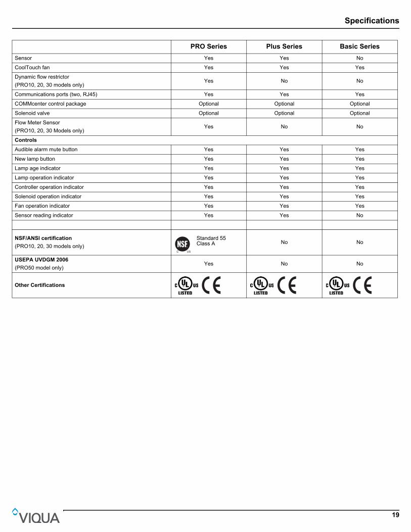
PRO Series Plus Series Basic Series
Sensor Yes Yes No
CoolTouch fan Yes Yes Yes
Dynamic flow restrictor(PRO10, 20, 30 models only)
Yes No No
Communications ports (two, RJ45) Yes Yes Yes
COMMcenter control package Optional Optional Optional
Solenoid valve Optional Optional Optional
Flow Meter Sensor(PRO10, 20, 30 Models only)
Yes No No
Controls
Audible alarm mute button Yes Yes Yes
New lamp button Yes Yes Yes
Lamp age indicator Yes Yes Yes
Lamp operation indicator Yes Yes Yes
Controller operation indicator Yes Yes Yes
Solenoid operation indicator Yes Yes Yes
Fan operation indicator Yes Yes Yes
Sensor reading indicator Yes Yes No
NSF/ANSI certification
(PRO10, 20, 30 models only)Standard 55 Class A No No
USEPA UVDGM 2006
(PRO50 model only)Yes No No
Other Certifications

Manufacturer’s Warranty
20
Section 8 Manufacturer’s Warranty
Our Commitment
VIQUA is committed to ensuring your experience with our products and organization exceeds your expectations. We have manufactured your UV disinfection system to the highest quality standards and value you as our customer. Should you need any support, or have questions about your system, please contact our Technical Support team at 1.800.265.7246 or [email protected] and we will be happy to assist you. We sincerely hope you enjoy the benefits of clean, safe drinking water after the installation of your VIQUA disinfection system.How to Make a Warranty Claim
Note: To maximise the disinfection performance and reliability of your VIQUA product, the system must be properly sized, installed and maintained. Guidance on the necessary water quality parameters and maintenance requirements can be found in your Owner’s Manual.
In the event that repair or replacement of parts covered by this warranty are required, the process will be handled by your dealer. If you are unsure whether an equipment problem or failure is covered by warranty, contact our Technical Support team at 1.800.265.7246 or e-mail [email protected]. Our fully trained technicians will help you troubleshoot the problem and identify a solution. Please have available the model number (system type), the date of purchase, the name of the dealer from whom you purchased your VIQUA product (“the source dealer”), as well as a description of the problem you are experiencing. To establish proof of purchase when making a warranty claim, you will either need your original invoice, or have previously completed and returned your product registration card via mail or online.Specific Warranty Coverage
Warranty coverage is specific to the VIQUA range of products. Warranty coverage is subject to the conditions and limitations outlined under “General Conditions and Limitations”.Ten-Year Limited Warranty for VIQUA UV Chamber
VIQUA warrants the UV chamber on the VIQUA product to be free from defects in material and workmanship for a period of ten (10) years from the date of purchase. During this time, VIQUA will repair or replace, at its option, any defective VIQUA UV chamber. Please return the defective part to your dealer who will process your claim.Five-Year Limited Warranty for Electrical and Hardware Components
VIQUA warrants the electrical (controller) and hardware components to be free from defects in material and workmanship for a period of five (5) years from the date of purchase. During this time, VIQUA will repair or replace, at its option, any defective parts covered by the warranty. Please return the defective part to your dealer who will process your claim.One-Year Limited Warranty for UV lamps, Sleeves, and UV Sensors
VIQUA warrants UV lamps, sleeves, and UV Sensors to be free from defects in material and workmanship for a period of one (1) year from the date of purchase. During this time, VIQUA will repair or replace, at its option, any defective parts covered by the warranty.Your dealer will process your claim and advise whether the defective item needs to be returned for failure analysis.Note: Use only genuine VIQUA replacement lamps and sleeves in your system. Failure to do so may seriously compromise disinfection performance and affect warranty coverage.
General Conditions and Limitations
None of the above warranties cover damage caused by improper use or maintenance, accidents, acts of God or minor scratches or imperfections that do not materially impair the operation of the product. The warranties also do not cover products that are not installed as outlined in the applicable Owner’s Manual.Parts repaired or replaced under these warranties will be covered under warranty up to the end of the warranty period applicable to the original part.The above warranties do not include the cost of shipping and handling of returned items.The limited warranties described above are the only warranties applicable to the VIQUA range of products. These limited warranties outline the exclusive remedy for all claims based on a failure of or defect in any of these products, whether the claim is based on contract, tort (including negligence), strict liability or otherwise. These warranties are in lieu of all other warranties whether written, oral, implied or statutory. Without limitation, no warranty of merchantability or of fitness for a particular purpose shall apply to any of these products.VIQUA does not assume any liability for personal injury or property damage caused by the use or misuse of any of the above products. VIQUA shall not in any event be liable for special, incidental, indirect or consequential damages. VIQUA’s liability shall, in all instances, be limited to repair or replacement of the defective product or part and this liability will terminate upon expiration of the applicable warranty period.

425 Clair Rd. W, Guelph, Ontario, Canada N1L 1R1t. (+1) 519.763.1032 • tf. (+1) 800.265.7246 (US and Canada only)
t. (+31) 73 747 0144 (Europe only) • f. (+1) 519.763.5069e-mail: [email protected]
www.viqua.com