owner’s manual - b2audio.com · high pass filter high pass multiplier ... the double sided pcb...
TRANSCRIPT

OWNER’S MANUAL
MODEL: M1 Product id:M108D

Foreword
The amplifier features a unique design, a variety of applications & highest possible effiency.
To obtain the full potential of the amplifier, it is crucial to upgrade the stock electrical system. Failure to doing so, limits the performance of the amplifier & may cause damage to the unit.In order to minimize errors & increase performance, read through the whole manual prior
Installation can preferably be carried out by an authorized dealer.
Better BassBetter Bass is our philosophy of adding something extra. Keep in mind that continious exposure to SPL above 100 dB can seriouslydamage your hearing. Today’s high power auto sound systems can easilyproduce SPL over 140 dB. Enjoy your music with sense.
Table of contents
1. Design features ....................... 3
2. Panel layout ............................ 4
3. Installation ............................. 5-9
3.1 Installation considerations ...... 5
3.2 Power / Speaker connectors .... 5 - 7
3.3 Daisy chain connection............ 7 - 8
4. Troubleshooting ...................... 9
2
to installing the M1.
We congratulate you with your decision to purchase the M1 amplifier.Every product developed by implements the keystones of our company philosophy; Optimum sound reproduction within its range, etter ass & high performance.These elements will enable you to reproduce music the way you prefer.
Feel free to visit us at: www.b2audio.com & www.facebook.com/sweetlikedanish
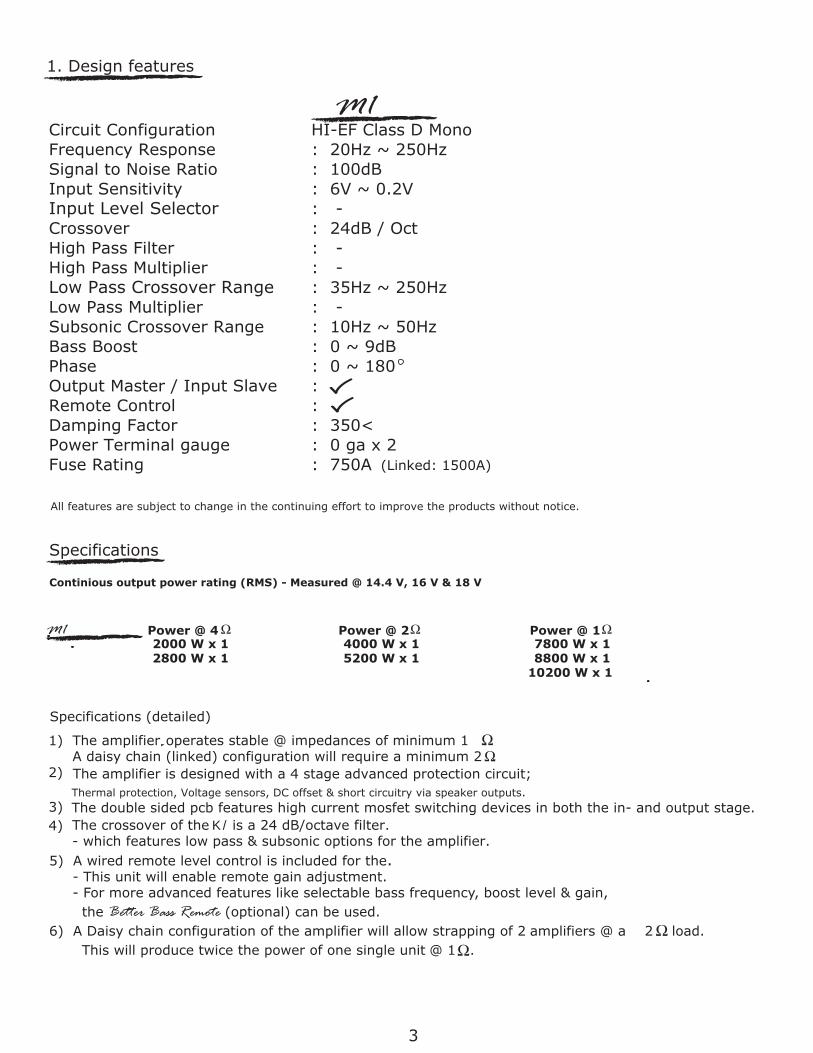
1. Design features
Circuit ConfigurationFrequency Response Signal to Noise Ratio Input Sensitivity Input Level SelectorCrossover High Pass Filter High Pass Multiplier Low Pass Crossover Range Low Pass MultiplierSubsonic Crossover Range Bass Boost PhaseOutput Master / Input Slave :Remote ControlDamping Factor Power Terminal gaugeFuse Rating
HI-EF Class D Mono: 20Hz ~ 250Hz: 100dB: 6V ~ 0.2V: -: 24dB / Oct: -: -: 35Hz ~ 250Hz: -: 10Hz ~ 50Hz : 0 ~ 9dB: 0 ~ 180
: : 350<: 0 ga x 2: 750A (Linked: 1500A)
All features are subject to change in the continuing effort to improve the products without notice.
Specifications (detailed)
2) The amplifier is designed with a 4 stage advanced protection circuit; Thermal protection, Voltage sensors, DC offset & short circuitry via speaker outputs.
The double sided pcb features high current mosfet switching devices in both the in- and output stage.
5) A wired remote level control is included for the. - This unit will enable remote gain adjustment. - For more advanced features like selectable bass frequency, boost level & gain,
This will produce twice the power of one single unit @ 1 .
Specifications
Continious output power rating (RMS) - Measured @ 14.4 V, 16 V & 18 V
1)
4)
3
3)
M1
M1 Power @ 4 Power @ 2 Power @ 1
The amplifier,operates stable @ impedances of minimum 1 .A daisy chain (linked) configuration will require a minimum 2 .
The crossover of the M1 is a 24 dB/octave filter.- which features low pass & subsonic options for the amplifier.
the Better Bass Remote (optional) can be used. 6) A Daisy chain configuration of the amplifier will allow strapping of 2 amplifiers @ a 2 load.
2000 W x 1 4000 W x 1 7800 W x 1 2800 W x 1 5200 W x 1 8800 W x 1 10200 W x 1

2. Panel layout
INPUTSignal input from the head unit. A minimum level input of 0.2V is essential for correct operation.
OUTPUTOutput RCA for signal routing to another amplifier.
POWER & PROTECTION INDICATORPower LED, Blue-lit shows correct operation. Protect LED, Red-lit shows general malfunction, faulty connection or thermal protection.
GAIN (6V ~ 0.2V)Matching of the output voltage from the head unit’sRCA line-outs to the input section.
SUBSONIC FILTER (10Hz ~ 50Hz @ 24dB/Oct)Adjusts the subsonic cut off point to eliminatefrequencies within the filter’s range.
BASS BOOST Variable bass boost with 0-9 dB @ 45 Hz.
REMOTE LEVEL CONTROL PORTConnection of external level control. (The Better Bass Remote can be connected for additional features).
LOW PASS FILTER (35Hz ~ 250Hz @ 24dB/Oct)Adjusts the cut off point for the low pass filterwithin the filter’s range.PHASE CONTROLVariable phase adjustment from 0-180 degrees.
OUTPUT MASTER / INPUT SLAVE For daisy chain connection of 2 amplifiers.Minimum impedance is 2 .
4
REM ( REMOTE )
SPEAKER OUTPUTS
Minimum speaker cable is 12 gauge. The minimum impedance is 1 ohm if used as a single unit.
GND ( GROUND CONNECTION )
For optimum performance 0 gauge cable isrecommended.
+12V ( POWER CONNECTION )For connection to the positive terminal of the battery (+12). For optimum performance 0 gauge cable is recommended.
For connection to the chassis' ground. Connect to switched +12V with trigger from head unit.
The ampli�er’ s connection to the loudspeakers.
Power connetors
M1
In linked mode the M1 o�ers stable opearation to a minimum of 2 ohms.

3. Installation
3.1 Installation considerations
If you choose to install the amplifier by yourself, please read the owner’s manual carefully. Before you start your installation, please take all steps into consideration.
configure your set up.
Preparation
Disconnect the negative (-) battery cable before mounting or making any connection. Check the battery and alternator ground (-) connection. Make sure they are properly connected and free of corrosion. Before selecting a mounting location for the amplifier, please take cooling and safety into consideration. Avoid areas with excessive vibration! The amplifiers have been designed with a good heat dissipation heatsink. In order to avoid excessive heat from the amplifier, it is recommended to find a mounting location that allows for vertical positioning of the heat sink fins.
For safety purposes, install the amplifier in a dry and well ventilated location and make sure no cables or other harness of the car is interfaced with the mounting location or will present a hazard to the car’s cable, control cables, fuel lines/tanks, hydraulic lines or other components of the vechicle.
3.2 Power connectors
12V (Power connection)Before mounting the amplifier, disconnect the negative (-) wire from the battery to protect any accidentaldamage to the amplifier or the audio system.The amplifier is equipped with dual 0 AWG power and ground terminals. Connect the power cables to power terminal labeled as +12V.
Make sure that the fuses and the fuse holder is adequate for the desired application.
GND (Ground connection)Locate a secure grounding connection as close as possible to the amplifier.Make sure the location is clean and provides a direct electrical connection to the chassis of the vehicle. Connect one end of an equal sized cable as the positive cable to the location of ground.It is important that the ground cable is as short as possible, but no longer than 75 cm at maximum.Run one end of the cable to the grounding point.Run the other end of the cable to the mounting location.Connect the ground cable to the terminal labeled as GND.
REM ( REMOTE CONNECTION )Run a remote turn on cable from the switched +12V source. This may be a toggle switch, a relay, the source unit's remote ouput cable or power antenna trigger cable.Connect the remote turn on cable to the power terminal labeled as REM.
5
The M1 is not equipped with fuses, so external fuses are required.Connect one end of the fuse holder to the power cable and the other end of the fuse holder to the positive battery terminal within 20 cm of the same cable.This fuse location will protect the system and the vehicle against the possibility of a short circuit in the power cable.
If in doubt, please contact authorized distributors / dealers that will be able to

+12V, GND, REM CONNECTION DIAGRAM
CAUTION
The minimum impedance is 1 ohm as a single unit.In linked mode the minimum impedance is 2 ohm.
Keep speaker cables away from power cables and the ampli�er’s RCA input cables. Use grommets anywhere the cables have to penetrate the vehicle’s chassis. Connect the speakers according to terminals on each speaker.Strip 3/8" of insulation from the end of each cable and twist the cables strands together tightly.Make sure there are no stray strands that might touch other cables or terminals which may cause a short.
8 ohm
~ 1ohms
FUSE
Ground
Remote turn on
Main Battery
12V
Headunit
750A
We recommend to use 12 gauge speaker cables for increased performance.Run 12 AWG speaker connecting cables from your speakers to the ampli�er's mounting location.
Crimp spade plugs over the cable ends or tin the ends with solder to provide a secure hold.Connect the cable ends to the ampli�er as shown on the speaker system diagram.
SPEAKER CONNECTION DIAGRAM
6
3.2 POWER / SPEAKER CONNECTIONS

8 ohm
~ 2ohms
3.3 DAISY CHAIN CONNECTION
Daisy chain connection allows linking of 2 mono ampli�ers to work as 1.
Step 1. Connect the master ampli�er to the head-unit and set its output master
Step 2. Connect the master and slave ampli�er in daisy chain Rca jack as shown in the diagram.
DAISY CHAIN CONNECTION DIAGRAM I
MASTER AMPLIFIER
HeadUnit
SLAVE AMPLIFIER
Please read the following connection diagram cautiously to ensure the correct connection.
and input slave switch to the output master position.
Step 3. Set the slave ampli�er output master & input slave switch to the slave input position.
7
SPEAKER CONNECTION DIAGRAM II
CAUTION
FUSE
Main Battery
12V
Headunit
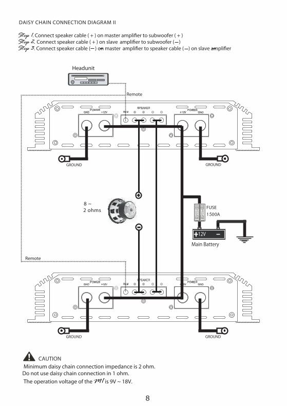
DAISY CHAIN CONNECTION DIAGRAM II
Step 1. Connect speaker cable ( + ) on master ampli�er to subwoofer ( + )Step 2. Connect speaker cable ( + ) on slave ampli�er to subwoofer ( )Step 3. Connect speaker cable ( ) on master ampli�er to speaker cable ( ) on slave ampli�er
GROUND GROUND
GROUNDGROUND
8 ~2 ohms
Remote
Remote
1500A
8
Minimum daisy chain connection impedance is 2 ohm.Do not use daisy chain connection in 1 ohm. The operation voltage of the M1 is 9V ~ 18V.
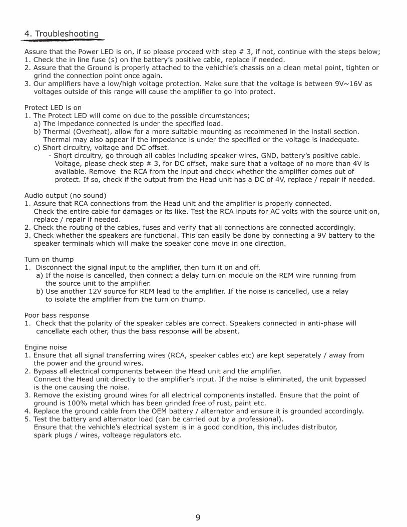
4. Troubleshooting
Assure that the Power LED is on, if so please proceed with step # 3, if not, continue with the steps below;1. Check the in line fuse (s) on the battery’s positive cable, replace if needed.2. Assure that the Ground is properly attached to the vehichle’s chassis on a clean metal point, tighten or grind the connection point once again.3. Our amplifiers have a low/high voltage protection. Make sure that the voltage is between 9V~16V as voltages outside of this range will cause the amplifier to go into protect.
Protect LED is on1. The Protect LED will come on due to the possible circumstances; a) The impedance connected is under the specified load. b) Thermal (Overheat), allow for a more suitable mounting as recommened in the install section. Thermal may also appear if the impedance is under the specified or the voltage is inadequate. c) Short circuitry, voltage and DC offset. - Short circuitry, go through all cables including speaker wires, GND, battery’s positive cable. Voltage, please check step # 3, for DC offset, make sure that a voltage of no more than 4V is available. Remove the RCA from the input and check whether the amplifier comes out of protect. If so, check if the output from the Head unit has a DC of 4V, replace / repair if needed.
Audio output (no sound) 1. Assure that RCA connections from the Head unit and the amplifier is properly connected. Check the entire cable for damages or its like. Test the RCA inputs for AC volts with the source unit on, replace / repair if needed.2. Check the routing of the cables, fuses and verify that all connections are connected accordingly.3. Check whether the speakers are functional. This can easily be done by connecting a 9V battery to the speaker terminals which will make the speaker cone move in one direction.
Turn on thump1. Disconnect the signal input to the amplifier, then turn it on and off. a) If the noise is cancelled, then connect a delay turn on module on the REM wire running from the source unit to the amplifier. b) Use another 12V source for REM lead to the amplifier. If the noise is cancelled, use a relay to isolate the amplifier from the turn on thump.
Poor bass response1. Check that the polarity of the speaker cables are correct. Speakers connected in anti-phase will cancellate each other, thus the bass response will be absent.
Engine noise1. Ensure that all signal transferring wires (RCA, speaker cables etc) are kept seperately / away from the power and the ground wires.2. Bypass all electrical components between the Head unit and the amplifier. Connect the Head unit directly to the amplifier’s input. If the noise is eliminated, the unit bypassed is the one causing the noise.3. Remove the existing ground wires for all electrical components installed. Ensure that the point of ground is 100% metal which has been grinded free of rust, paint etc.4. Replace the ground cable from the OEM battery / alternator and ensure it is grounded accordingly.5. Test the battery and alternator load (can be carried out by a professional). Ensure that the vehichle’s electrical system is in a good condition, this includes distributor, spark plugs / wires, volteage regulators etc.
.
9

M1