owners manual c f 2 0 - 1 5 0 - dramm corporation, 920.684 ... · other application procedures...
TRANSCRIPT

C O L D F O G G E R™
Owners Manual
C F 2 0 - 1 5 0

Coldfogger Manual 2CF2--150MAN1Printed in the U.S.A. Revised: 6/2011

Limited WarrantyDramm Corporation warrants to the extent of the purchase price, that the Coldfogger will be free
from defects in materials and workmanship to the original purchaser for a period of six months.Parts subject to wear are not covered under this limited warranty. Defects or damages due to themisuse, non-observance of safety standards, or non-observance of EPA chemical guidelines are notcovered under this limited warranty. Please read and follow the instructions and heed warningsstated in the operating manual and on the Coldfogger.
Dramm Corporation makes no other further warranty, expressed or implied, and all other orfurther warranties, including any warranties of merchantability or fitness for a particular purposeare expressly excluded.
In no event shall Dramm Corporation be liable for loss of product, profit or any other special,incidental or consequential damages including, but not limited to, plant damage, property orpersons.
This warranty begins on the date of original purchase. If warranty service is required, theequipment must be sent prepaid to:
Coldfogger ServiceDramm Corporation
2000 North 18th StreetManitowoc, WI 54220
Dramm Corporation makes no warranty, expressed or implied, in regard to the efficacy of anypesticide or other chemical which may be applied using the Coldfogger.
C O L D F O G G E R™
Coldfogger Manual 3
__________________ Date Passed Final Systems Test
By: ____________________________________________
––––––––––––––––––––––––––––––––––––––––––––––––
––––––––––––––––––––––––––––––––––––––––––––––––
––––––––––––––––––––––––––––––––––––––––––––––––
––––––––––––––––––––––––––––––––––––––––––––––––
Model: CF20-150120 volt 60 HZ
10 AMP Single-Phase
________________________________________Serial Number
Test Run & Final Inspection
Shipped To:

Coldfogger Manual 4
Table of Contents
Warranty ................................................................................4
Warning..................................................................................5
How Does My Coldfogger Work? ..........................................6
Greenhouse & Nursery Application Procedures................7-8
Pest Control & Vaccines Application Procedures ................8
Chemical Dilution Rate Chart ..............................................9
Starting Procedure ..............................................................10
Shut Down Procedures & Cleaning ....................................11
Cleaning & Maintenance ....................................................12
Plumbing Assembly Diagram ..............................................13
Plumbing Parts List ............................................................14
Hose Reel Guide Assembly..................................................15
Frame Parts List ..................................................................16
Pump Parts Diagram............................................................17
Pump Parts List ..................................................................18
Spray Gun Parts ..................................................................19
Coldfogger CF20-150 Specifications ..................................20
Troubleshooting ............................................................21-23
Notes ..............................................................................24-25

The Dramm CF20-150 Coldfogger operates at 2800 - 3000 PSI and applies toxicchemicals. Extreme caution must be used! Read all warnings. Serious injury ordeath can occur from misuse.
WARNING
Coldfogger Manual 5
• Do not operate machine without readingall warnings and instructions.
• Owners or Managers: It is yourresponsibility to inform and instruct anyemployee who uses this machine in regardsto safety and operational procedures.
When Spraying:
• Do not place your hand or fingers intothe spray pattern – vaccination or injectionof toxic chemicals will occur.
• Never aim the spray at yourself or anyperson.
• Always increase the pressure slowly.
• Always decrease the pressure beforeshutdown.
• Always release (squeeze the spray guntrigger) the pressure on the spray gunbefore removing or before shutdown.
• The spray hose is a high pressurereinforced hose with special couplings. Donot bend the hose or drag it over sharpobjects. If a leak develops do not use thehose or try to repair it. Send damagedhoses to the Dramm Corporation forinspection. No warranty will cover a hose ifit has been bent, kinked, abused or draggedover sharp objects.
• When mixing and spraying, always wearprotective clothing - Full face mask, spraysuit, cap, hood, boots, and gloves.
• If machine is used for insecticide,fungicide, or disinfectants - never use it forvaccines or any other application. If
purchased for vaccine application never useit for any other applications.
• Follow all E.P.A. guidelines for applyingchemicals, and apply chemicals at thelabeled rates.
• Ensure that the pump never exceeds themaximum operating pressure of 3200 PSI.
• Engage the safety lock on the spray gunwhen not spraying.
• When applying chemicals using the lowvolume method, (concentrated chemicalsolution) do not spray directly at plants.
• If injury occurs while spraying, see adoctor immediately with full labels ofproduct being used. Do not treat as a minorinjury!
• Check that all electrical connections andchemical piping connections are secure.
• Connect the electrical power cord to agrounded electrical outlet of the appropriatevoltage and frequency.
• Keep all electrical connections aw a yfrom liquids.
• Use only 12 gauge grounded extensioncords. (Fifty foot maximum).
• Do not leave chemicals or water in thetank, pump, suction lines, or dischargehose.
• Before servicing, unplug the Coldfoggerfrom the electrical source.

The motor has an 8.5 amp self-resettingthermal overload protection cut off. In the eventof an overload, voltage drop, or over heating– themotor automatically shuts down. After a periodof 3 - 4 minutes the pump can be turned onsafely. The 18 foot main power cord isgrounded. If you use extension cords, theyshould be #12 gauge grounded cords– andshould not exceed 50 feet.
A high quality hydraulic oil (H32) is used inthe machine. It should be changed after the first100 hours of use. Thereafter it can be changedafter every 500 hours of use, or every 6 months.See Cleaning & Maintenance on page 13.
A special discharge hose and spray gun havebeen chosen for the Coldfogger. Do not abuse,bend or drag hose over sharp objects. Do not tryto repair discharge hoses or use them when aleak has developed. A filter is built into the gunto help prevent clogging. See Cleaning &Maintenance on page 13 This should beremoved and cleaned after every 10 to 20 hoursof use. There is also a special filter built intothe chemical tank. The tank and filter should beflushed or rinsed after every use.
The CF20-150 Coldfogger is designed toapply chemicals in greenhouses, nurseries,poultry barns, livestock barns, and buildings. Itoperates at an average pressure of 2800-3000 PSIproducing a very small particle, 30-40µ (microns)average. It is designed to apply chemicals usingthe low-volume (LV) principle, but it can also beused to apply chemicals using the high volume(HV) principle. If you use the low volumemethod, application times will be approximately10 times faster then under the high volumemethod. This machine is designed to applyinsecticides, fungicides, growth retardants,disinfectants and vaccines. Do not use thismachine to apply viscus materials such asshading compounds or paints.
Low Volume Method: The application ofchemicals at the labeled rate prescribed for agiven area, but diluted into greatly reducedamounts of water or diluents. Low volumeapplication can only be accomplished withspecial equipment which produces very smallspray particles.
High Volume Method: The application ofchemicals at rates prescribed on the chemicallabel, diluted into the specified amount of water.Normally this is "X" ounces of chemical dilutedinto 100 gallons of water. Equipment whichapplies chemicals under the high volumeprinciple, generally produce spray particles inthe range of 100 to 150µ (microns) in diameter.
The CF20-150 Coldfogger operates from a120 volt– 60HZ 60HZ single-phase electric motorwhich drives a hydraulic diaphragm pump. Thishydraulic pump is designed to producepressures up to 3200 PSI.
CAUTION: Do not operate at pressures over3200 PSI and never force the Pressure Regulatorbeyond the stop position. The high performancepump produces an average discharge rate of 52liters (13.6 gallons) per hour. The spray ispropelled 20 to 25 feet. The machine isequipped with a 72 liter (20 gallon) tank. Whenapplying 10 liters (2.63 gallons) per 10,000square feet, you can treat 45,000 square feet in45 minutes using the low volume method.
How Does My Coldfogger Work?
Coldfogger Manual 6

Greenhouse & Nursery Application Procedures
A. Secure the treatment area and post hazardsigns b e f o r e spraying. No humans or petsshould be present.
B. Follow all EPA Guidelines regarding theapplication of chemicals.
C. Chemicals should only be applied bylicensed applicators.
The Dramm Coldfogger produces an averagedroplet size of 40µ. As explained previously, theColdfogger uses a reduced volume of water(diluent) to apply chemicals ( this means thatthe spray is highly concentrated). To apply-spray over and through the crop at distancesgreater than 7 feet, then down the aisle as yourotate your hand. The Coldfogger uses highpressure to produce small droplets. High sprayvelocities result, aiding the ability of the spray torustle the plant canopy and reach the undersideof the leaves. The small particles will allowexcellent coverage at distances up to 25 feetfrom the gun. Different plants tolerate thisvelocity better than others. Use caution whenfirst using the Coldfogger on a new crop.Determine the sensitivity to damage from thisvelocity before deciding on how closely you mayspray the plants.Do not spray plants to “Run-Off” or “Glisten” under the low volume methodof application. After spraying the plants, novisible residue should be seen on the foliage.
Growth regulator applications should bemade at conventional high volume rates to avoidany miscalculations and over-application. Note -when applying B-9 the foliage should be wet.
APPLICATION PROCEDURES
The Coldfogger is a low-volume applicator.The chemical solution will be highlyconcentrated and only 5 to 15 liters of solutionwill treat 10,000 square feet. We recommend arate of 10 liters per 10,000 square feet (or 1 literper 1,000 square feet for potted or beddingplants). Use more total solution for cut flowers,tomatoes,
...anything with more plant mass. Similarly, lesssolution can be used for plugs and seedlings.
The Coldfogger will apply emulsifiableconcentrate, wettable powder, and flowablechemical formulations.
CHEMICAL DILUTION CALCULATION
You will apply chemical at labeled rates persquare foot area, but with less water. To find thecorrect dosage of chemical for 10,000 squarefeet of treatment area multiply the labeled rateper 100 gallons by 0.4. Example:
16 ounces X 0.4 = 6.4 ounces
Mix this quantity of chemical into 10 liters ofwater and apply over 10,000 square feet. Foreasy reference, use the dilution rate chart onpage 9 for the correct dosage.
Adjust the amounts of chemical and waterfor the exact amount of area you wish to treat.The example calculations above are for 10,000square feet. This rate calculation is based onbedding and potted plants. In grower surveys,on average 40 gallons of spray solution was usedto treat 10,000 square feet. For different cropsthis amount may vary greatly. Rose or tomatogrowers may use as much as 200 - 300 gallonson 10,000 square feet. You may need to adjustyour spray solution accordingly.
MIXING CHEMICALS & FILLING TANK
FOR 10,000 SQUARE FEET
Add 5 liters of clear water to the tank andstart the agitator. Test your Coldfogger withclear water as described on page 10. Mix yourchemical into the remaining 5 liters of water andpour through a 40 mesh strainer into the tank.
When using wettable powders make a "lump-free" paste, then slowly dilute it with theremaining 5 liters of water.
GREENHOUSE & NURSERY APPLICATIONS
GREENHOUSE & NURSERY APPLICATIONS cont...TREATMENT AREA PRECAUTIONS
Coldfogger Manual 7

Other Application Procedures
Coldfogger Manual 8
If the Coldfogger is being used to spraydisinfectants, direct application is permitted.Spray directly into wall cracks, joints and inaccessible corners until covered with a moistresidue. Stand about 10 feet from the target.The larger 0.015" nozzle tip is recommended inorder to obtain a moist, heavy spray.
This application requires direct spraying oftarget surfaces for only a short time. Walls,cracks, joints and corners can be sprayeddirectly from a distance of about 10 feet until amoist residue appears on the treatment surface.
Vaccines can be applied using conventional(HIGH VOLUME) rates. Do not spray animalsdirectly. For effective applications– generate alarger spray droplet by using the 0.015" nozzletip.
SPRAYING/ FOGGING
Position the Coldfogger in the main middleaisle. Proceed to the end of the bench. Begin tospray the crop. Move rapidly back to theColdfogger while treating benches on both sidesof the aisle. See Figure 1. The fog will travel 20to 25 feet. Your walking speed should beadjusted to treat 1,000 square feet in 1 minuteor 10,000 square feet in 10 minutes. Itfacilitates application if an extra person is usedto reel up the hose as the applicator movestowards the sprayer.
Remember, DO NOT spray the plants tooclosely and DO NOT spray to "RUN OFF" or"GLISTEN".
GREENHOUSE & NURSERY APPLICATIONS cont...
PEST CONTROL
VACCINES
DISINFECTION
Greenhouse & Nursery Application Procedures continued...
Figure 1

USE THIS AMOUNT OF CHEMICAL IN100 GALLONS OF WATER
AT THE LABELED RATE
10 LITERS OF WATER AND FOGOVER 10,000 SQUARE FEET
1.0 ounces 0.4 ounces2.0 ounces 0.8 ounces3.0 ounces 1.2 ounces4.0 ounces 1.6 ounces5.0 ounces 2.0 ounces6.0 ounces 2.4 ounces7.0 ounces 2.8 ounces8.0 ounces 3.2 ounces9.0 ounces 3.6 ounces
10.0 ounces 4.0 ounces11.0 ounces 4.4 ounces12.0 ounces 4.8 ounces13.0 ounces 5.2 ounces14.0 ounces 5.6 ounces15.0 ounces 6.0 ounces16.0 ounces 6.4 ounces17.0 ounces 6.8 ounces18.0 ounces 7.2 ounces19.0 ounces 7.6 ounces20.0 ounces 8.0 ounces21.0 ounces 8.4 ounces22.0 ounces 8.8 ounces23.0 ounces 9.2 ounces24.0 ounces 9.6 ounces25.0 ounces 10.0 ounces26.0 ounces 10.4 ounces27.0 ounces 10.8 ounces28.0 ounces 11.2 ounces29.0 ounces 11.6 ounces30.0 ounces 12.0 ounces31.0 ounces 12.4 ounces32.0 ounces 12.8 ounces
HOW TO USE THIS CHART: Refer to the selected chemicals labeled rate instructions. Find the raterecommended for 100 gallons of water and match that amount with the number in the left handcolumn of the chart. Then read across to the right side of the chart to find the proper chemicalamount for use in the CF20-150 Coldfogger. If you are unable to make this calculation, pleasecontact the Dramm Corporation at 1-(800)-258-0848 for assistance.
Coldfogger Manual 9
Coldfogger Dilution Rate Chart

Coldfogger Starting Procedures
1. Plug the Coldfogger into a 120 volt 60 H Zgrounded outlet.
2. Turn the power switch to the A G I T A T I O Nposition. See Figure 2.
3. Turn the Priming Valve counter-clockwise tothe zero "0" marking.
4. Turn the Pressure Regulator counter-clockwise to the zero "0" marking.
5. Add clear water and proceed to steps 6through 11– t e s t i n g the Coldfogger with clearwater.
6. Turn power switch to the P U M P p o s i t i o n .See Figure 2.
7. Operate the machine for 2 minutes withoutpressure. This will vent the hydraulic system.
8. Turn the Pressure Regulator clockwise– thiswill prime the pump. Run for approximately 2minutes– until the by-pass hose vibrates and themotor sound changes pitch.
9. Turn the Pressure Regulator counter-clockwise– or back to its' original position zero"0".
10. Close the Priming Valve by turning itclockwise. The unit is now ready to increasepressure.
11. SLOWLY turn the Pressure Regulatorclockwise until the Pressure Gauge reads 3,000PSI.
12. Spray with clear water to test the Coldfogger.Add the remaining water and chemical mix.
13. Commence to spray. Remember that thehose and some of the plumbing is filled withclear water from the test procedures. There isapproximately 4 liters or 1 gallon to be foggedbefore the chemical solution is present.
In situations where the Coldfogger hasremained unused for a period of time, it may benecessary to plunge the intake valve. This maybe done by removing the solution line andpushing the valve open several times with theeraser of a pencil or similar tool. Replace thesolution line and proceed normally.
STARTING PROCEDURES
FIRST TIME OPERATION AFTER A PERIOD OF NO USE
Coldfogger Manual 10
Figure 2

IMPORTANTAFTER THE FIRST USE IT IS NECESSARY TO
TIGHTEN DOWN THE 4 CAP SCREWS ON THEPUMP HEAD. TORQUE THE PUMP HEAD DOWNDIAGONALLY WHEN THE PUMP IS COOL.TORQUE THE PUMP HEAD CAP SCREWS DOWNTO 50 NM (37 FT/LB).
GENERAL
1. Because it is possible that air may enter thehydraulic system during transport, the systemmust be "vented" or operated without solutionfor a few minutes. The hydraulic system ventsautomatically when the pump motor is operatedwhile the Priming Valve, (or Unloading Valve)and Pressure Regulator have been fully rotatedcounterclockwise. Follow standard operatingprocedures after venting the hydraulic systemfor 2 minutes.
2. The Intake Valve may stick and not allow thepump to prime. Prime the pump with thePush/Pull knob (Pg. 11 Fig. 3 Item #10) on rearof pump head. In the event that the pump doesnot prime, drain the solution tank of all materialand remove the Hose Coupling at the pumphead. The Hose Coupling secures the SuctionIntake Tube to the Intake Valve. Push the ValveSpindle down with a small rod (located insidethe Intake Valve). Turn the pump "ON" and poura small amount of water into the Intake Valve.The pump should draw the water in.Reassemble the suction intake assembly andfollow the Coldfogger Starting Procedures onPage 10.
3. Use the solution tank Drain Valve ( P g . 1 3 ,Item #49, located under the Solution Tank,beside the Agitator. This grey valve drains thesolution tank when the arrow on the lever pointsto the drain hose (turned clockwise). Drain therinse water into a pail or 5 gallon bucket.Remember to close the Drain Valve (turnedcounterclockwise) before filling the SolutionTank with water and chemicals. See Figure 4.Note: to drain, agitation pump must operate. This willalso clean the agitation pump.
Shut Down Procedures and Cleaning
Coldfogger Manual 11
STOPPING SPRAY – PUMP SHUT-DOWN
1. Release the spray gun trigger.
2. Lock the spray gun safety knob.
3. Turn the Pressure Regulatorcounterclockwise(Item #4) to the "0" setting.
4. Turn the Priming Valve counterclockwise(Item#3) to the "0" setting.
5. Turn Pressure Regulator clockwise again todrain solution from the pump.
6. After 1 minute turn the Pressure Regulatorcounterclockwise.
7. Turn the Power Switch to the "OFF" position.(Pg.10, Fig.2).
8. Unlock the spray gun and squeeze the triggerto relieve any remaining pressure.
9. Be sure to again lock the spray gun safetyknob.
10. Wind up the discharge hose on the hose reel.
11. Rinse the solution tank, solution tank filter,discharge hose and spray gun with warm clearwater. Drain the cleaning solution using theDrain Valve (Pg.11, Fig.3, Item #7. Dispose ofthe rinse water properly.
12. Coil up power cord.
13. Store the Coldfogger in a dry, dust-freelocation. Cover with plastic and keep fromfreezing temperatures.
BEFORE SERVICING THE PUMP:
1. Turn the power switch "OFF" and disconnectfrom the power source.
2. Relieve the pressure from the pump byrotating the Priming Valve counterclockwise.
3. Relieve pressure from the spray gun bysqueezing the trigger.
4. Lock the spray gun safety knob.
MAINTENANCE & CLEANING
Figure 4

Cleaning & Maintenance
4. SPRAY GUN FILTER : Inside the spray gun isa cylinder filter or strainer that should becleaned every 10 - 20 working hours. Use a stiffbrush, never use a steel brush. If the spray gunfilter gets dirty or worn it will not spray properlyand should be cleaned or replaced.
5. SOLUTION TANK FILTER: Inside thesolution tank is a suction filter that should becleaned after every use with a stiff brush. Whenthis filter becomes dirty the solution will not beable to be drawn solution into the pump and theunit will not spray.
HYDRAULIC SYSTEM
1. The hydraulic oil is subject to wear andaging, so it is necessary to change this oil atleast once a year or after every 500 hours ofoperation. However, the first oil change must becarried out after the first 100 hours of operation.Change the oil while it is still warm.
2. Run the motor for about 30 seconds toremove the remaining oil.
3. Next, fill the gear box with a good qualityhydraulic oil (H32).
4. Vent the hydraulic system by running theunit with no pressure for a few minutes torelease any trapped air.
PUMP HEAD
1. The pump head must be replaced if the outletvalve seating is eroded or if erosion has effectedthe seating of the pump membrane assembly.Remove the pump head by remove the 4 capscrews. Torque down the pump head afterservicing to 50 NM (37 Ft/Lb). Do this when themachine has cooled down.
2. The piston pump membrane assembly isseparate from the pump head and the hydraulichousing and is held down by the 4 cap screws.Each time that the oil is changed the pumpmembrane should also be replaced to preventany breakdown while spraying.
PRESSURE REGULATOR (PUMP HEAD)
1. If the pressure regulator is damaged, then itis generally beyond repair and a new PressureRegulator should be installed.
SPRAY GUN
NEVER AIM THE SPRAY AT YOURSELF OROTHER PEOPLE.
DURING WORK PAUSES LOCK THE SPRAYGUN SAFETY KNOB.
CALL A DOCTOR IMMEDIATELY UPONINJURY FROM THE SPRAY.
REMOVE THE SPRAY GUN FROM THEDISCHARGE HOSE BEFORE MAINTENANCE.
1. Flush the spray gun thoroughly after eachuse with warm water.
2. Inside the gun handle is a filter that shouldbe cleaned regularly. Remove the hand guardand unscrew the spray gun handle. Pull out thefilter, rinse the gun and clean the filter with astiff brush (never use a steel brush).
3. Place the filter back into the gun with thefilter hole visible at the top and screw the handleflush to the gun head. Replace the hand guard.
SPRAY GUN NOZZLE TIP ASSEMBLY 1. Unscrew and remove the Cap Nut (Item# 1),place the Spray Tip (Item #2) into the Cap Nutand place the Nozzle Sealing (Item #3) in back ofthe jet. Screw the Cap Nut Assembly back ontothe gun Screw Piece (Item # 4). See Figure 5.
Coldfogger Manual 12
Figure 5
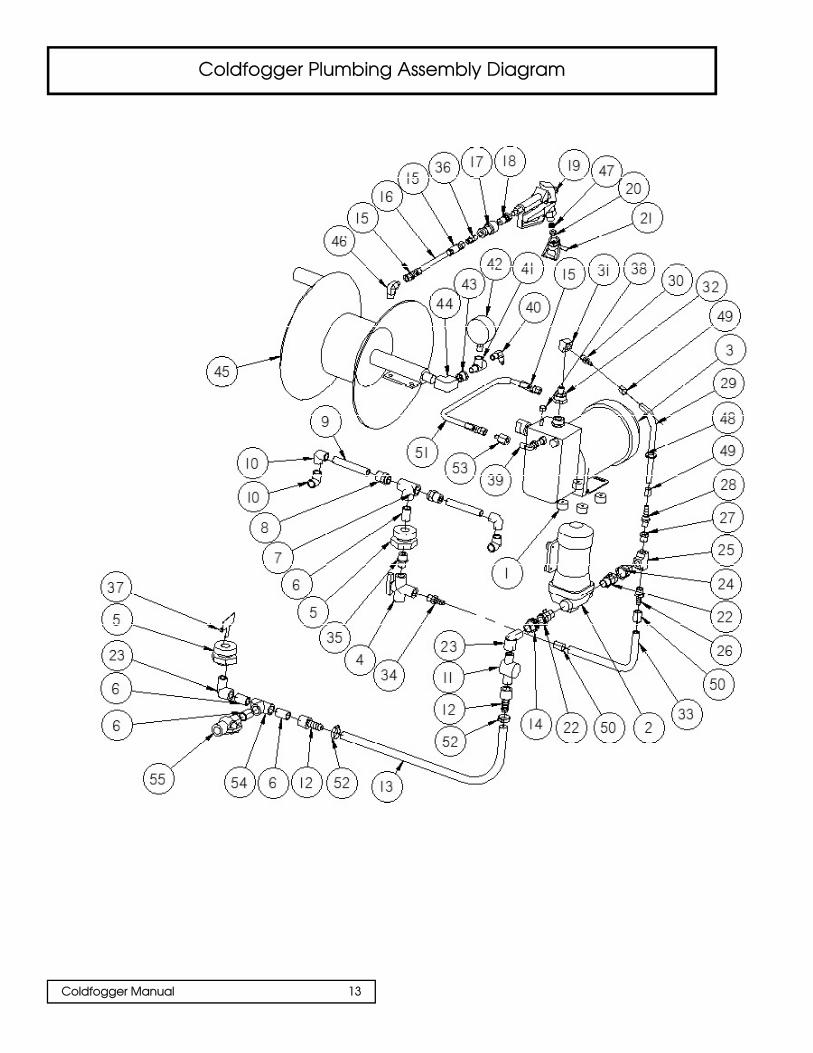
Coldfogger Plumbing Assembly Diagram
Coldfogger Manual 13

Coldfogger Manual 14
Plumbing Parts List

Coldfogger Manual 15
Coldfogger Hose Real Guide Assembly Diagram

Coldfogger Frame and Hose Reel Parts List
Coldfogger Manual 16

Coldfogger Pump Casing & Mechanism DiagramSECTION 1 & 3
Coldfogger Manual 17

Coldfogger Manual 18
PART #
AL116201AJ
MC014301AJ
MC014402AJ
AL045503AV
AL101500AV
AL072700AV
AL173000AV
AL172900AV
AL131501SV
AL045101AV
HP007118AV
AL013702AV
AL131401SV
AL133501SV
AL125900SV
AL129600SV
AL159500SV
ST070820AV
AL134400SV
AL134801SV
AL132100SV
AL147400SV
QTY.
1
1
1
1
1
1
1
1
1
8
1
1
1
1
1
1
1
4
1
1
1
Coldfogger Pump Casing & Mechanism Parts ListSECTION 1 & 3
# DESCRIPTION
1 Eccentric/Bearing
2 Motor (120V, 60HZ)
(240V, 60HZ)
3 Bearing with eccentric oil seal
5 Fan
6 Fan shroud
7 Cord
8 Switch
9 Piston kit
10 Faceplate
11 Faceplate screws
12 Faceplate gasket
13 Pressure valve
14 Replacement housing
15 Diaphragm
16 Outlet valve
17 Replacement block (120V, 60HZ)
(240V, /60HZ)
18 Prime button
19 Block bolts
20 Inlet Valve (120V, 60HZ)
(240V, 60HZ)
21 Prime/Spray valve
22 Hose adapter

Coldfogger Spray Gun Parts List & DiagramSECTION 8
ITEM # PART # COMPONENT # DESCRIPTION QUANTITY
Coldfogger Manual 19
-- AL245020LX -- Metal Spray Gun (Complete) 1
1 AL083000AV Gun diffuser 1
2 AL083700AV Trigger guard 1
3 AL083900AV Trigger 1
4 AL083800AV Ball, valve & plunger assembly 1
5 AL085800AV Trigger pin 1
6 AL086101AV Gun filter (100 mesh) 1
7 AL081300AV Gun swivel 1
8 AL083300AV Valve stem nut (3 pack) 1

Technical Data
Spray Droplet Size: 40µ (micron) average diameter (30 -60 micron spectrum)
Standard Nozzle Size: 0.013" (optional 0.015")Spray Pattern: 4 inch fan pattern Operating Pressure: 2,800 - 3,000 PSIDischarge Hose Burst Pressure: 9,000 PSIDischarge Hose Length: 150 feetOutput Rate: 1 liter (0.26 gallons) per minute 3,000 psiSolution Tank Volume: 45.6 liters (12 gallons)Power Requirements: 120 volt 60 HZ Auto 10 ampOverload Protection: Thermal overload / Auto resetShipping Weight: 255 lbsDimensions: Width: 21 inches
Length:39 inchesHeight: 43 inches
Standard equipment:
* Thermal overload protection* High pressure hand held spray gun with filter* Solution tank suction filter* Solution tank agitator* Solution tank drain valve* 150 foot high pressure discharge hose* Quick disconnect fitting on discharge hose for spray gun* Discharge hose reel with manual crank and hose guide* Power switch for agitator and pump motors* Mounted on a sturdy steel frame
Coldfogger CF20-150 Specifications
Coldfogger Manual 20

PROBLEM
Low spray pressure
Pump motor and agitator donot start.
Agitator works, but pumpmotor only hums.
CAUSE
Worn spray tip
No power or incorrectvoltage.
Thermal overload hastripped.
Clogged suction filter insolution tank.
Suction hose not securedtightly to pump head.
Closed or defective primervalve.
Hydraulic oil level too low.
Clogged intake valve (thevalve inside the inlet pass-age can be pushed down withcare).
Unit draws in air and notsolution.
Damaged intake valve.
Spray solution is too thick.
Open or defective pressureregulator allows solution backinto the solution tank.
REMEDY
Replace spray tip
Connect to 120 volt 60 Hzpowersource (10 amp fuse).
Auto reset - Wait for unit tocool off for restart
Clean or replace.
Clean wing nut coupling andtighten or replace wing nutcoupling gasket.
Open, clean or replace theprimer valve.
Top off the oil level in the pumphousing.
Unscrew wing nut coupling,turn the pressure regulatorclockwise and fill the inletpassage with water. Then pushdown the intake valve spindlewith a rod until the intake valveopens (an audible change willbe heard).
Check that all hoses are tightand not leaking.
Replace the intake valve.
Dilute the spraying solution.
Close or replace the pressureregulator.
Troubleshooting 1 of 3
Coldfogger Manual 21

Troubleshooting continued... 2 of 3
PROBLEM
Unit fails to draw solution.Pump draws in solution,but no pressure is created.
Pump draws in the solution,pressure builds up, but whenthe spray gun is opened thepressure drops.
Solution runs back into thetank when spray gun is closed.
Oil leaking between the pumphead and housing.
Unit shakes, motor does notrun.
CAUSE
Hydraulic oil level is low.
Air is in the hydraulic system.
Too much foam in the solutiontank. Spray solution is toothick.
No nozzle tip in the spray gun.
Orifice diameter is the nozzletip is clogged or worn.
Clogged suction filter.
Spray gun filter is clogged.
Spray solution is too thick.
Air is trapped in the suctionline.
Loose or defective pressureregulator.
Pump head bolts are loose.
Defective pump membrane.
Defective hydraulic control.
REMEDY
Top off the hydraulic oil.
Vent the hydraulic system.
Use an anti-foaming agent anddilute the spraying solution.
Insert a nozzle tip.
Clean or replace nozzle tip.
Clean or replace the suctionfilter.
Clean or replace the spray gunfilter.
Dilute the spraying solution.
Clean and tighten the wing nutcoupling and wing nut gasket.
Tighten or replace the pressureregulator.
Torque down pump head boltswith allen wrench.
Replace.
Qualified service is required.Contact Dramm Corporation service department at 1-800-258-0848.
Coldfogger Manual 22

Troubleshooting continued... 3 of 3
PROBLEM
Leaking nozzle tip on thespray gun.
Spray gun keeps on sprayingwhen the trigger is released.
Unit fails to draw solution.Pump draws in solution,but no pressure is created.
CAUSE
Damaged needle and valve seat.
Loose the retainer screw.
Damaged plastic gasket.
Defective pressure regulator.
Leaking intake valve.
REMEDY
Service the spray gun.
Pull the trigger and let it snapout a few times.
Tighten retainer screw.
Replace gasket.
Replace the pressure regulator.
Service or replace the valve.
Coldfogger Manual 23

Coldfogger Manual 24
Notes

Coldfogger Manual 25
Notes

Notes
2000 North 18th StreetP.O. Box 1960
Manitowoc, WI 54221-1960, USA920-684-0227 • 1-800-258-0848
FAX: [email protected]
CF20-150MAN16/2011