owner's manual and instructions - dragon agro
TRANSCRIPT

Available in eitherL.P. Gas VaporWithdrawal orNatural Gas
Configurations.
MODELS OUTPUT (Btuh) FUEL
HW220 220,000
Congratulations!
You have purchased the finest agricultural building heater available.
Your new L.B. White heater incorporates the benefits from the most experiencedmanufacturer of heating products using state-of-the-art technology.
We, at L.B. White, thank you for your confidence in our products andwelcome any suggestions or comments you may have...call us, toll-free,at (800) 345-7200.
Owner's Manual and InstructionsTherma Grow™ Greenhouse Heaters
150-27595
ATTENTION ALL USERS
This heater has been tested and evaluated by C.S.A. International, inaccordance with IAS U.S. Requirements for Gas-Fired Greenhouse Heaters,for use as a direct gas-fired circulating heater for the heating of greenhouses.If you are considering using this product for any application other than itsintended use, then please contact your fuel gas supplier, or the L.B. WhiteCo., Inc.


WARNINGFire and Explosion Hazard
■ Not for home or recreational vehicle use.■ Installation of this heater in a home or
recreational vehicle may result in a fire orexplosion.
■ Fire or explosions can cause propertydamage or loss of life.
FOR YOUR SAFETYIf you smell gas:1. Open windows.2. Don't touch electrical switches.3. Extinguish any open flame.4. Immediately call your gas supplier.
FOR YOUR SAFETYDo not store or use gasoline or otherflammable vapors and liquids in the vicinity ofthis or any other appliance.
WARNINGFire and Explosion Hazard
■ Keep solid combustibles a safe distanceaway from the heater.
■ Solid combustibles include wood or paperproducts, straw, and dust.
■ Do not use the heater in spaces whichcontain or may contain volatile or airbornecombustibles.
■ Volatile or airborne combustibles includegasoline, solvents, paint thinner, dustparticles or unknown chemicals.
■ Failure to follow these instructions mayresult in a fire or explosion.
■ Fire or explosions can lead to propertydamage, personal injury or loss of life.
GENERAL HAZARD WARNING
■ Failure to comply with the precautions and instructions provided with this heater, can result in:— Death— Serious bodily injury or burns— Property damage or loss from fire or explosion— Asphyxiation due to lack of adequate air supply or carbon monoxide poisoning— Electrical shock
■ Read this Owner’s Manual before installing or using this heater.
■ Only properly-trained service people should repair or install this heater.
■ Save this Owner’s Manual for future use and reference.
■ Owner’s Manuals and replacement labels are available at no charge. For assistance, contactL.B. White at 800-345-7200.
WARNING■ Proper gas supply pressure must be provided to the inlet of the heater.
■ Refer to dataplate for proper gas supply pressure.
■ Gas pressure in excess of the maximum inlet pressure specified at the heater inlet can causefires or explosions.
■ Fires or explosions can lead to serious injury, death, building damage, or loss of plant life.
■ Gas pressure below the minimum inlet pressure specified at the heater inlet may causeimproper combustion.
■ Improper combustion can lead to asphyxiation or carbon monoxide poisoning and thereforeserious injury or death to humans and plant life.
2
This Owner's Manual includes all options and accessoriescommonly used on this heater. However, depending on theconfiguration purchased, some options and accessoriesmay not be included.
When calling for technical service assistance, or for otherspecif ic information, always have model number,configuration number and serial number available. Thisinformation is contained on the dataplate. The dataplate islocated on the interior of either the burner end or motor enddoor.
This manual will instruct you in the operation and care ofyour unit. Have your qualified installer review this manualwith you so that you fully understand the heater and how itfunctions.
The gas supply line installation, installation of the heater,and repair and servicing of the heater requires continuingexpert training and knowledge of gas heaters and shouldnot be attempted by anyone who is not so qualified. Seepage 6 for definition of the necessary qualifications. Adetailed Installation and Service Guide is available, at nocharge, to qualified personnel by contacting the localL.B. White distributor, dealer or the L.B. White Company.
Contact your local L.B. White distributor or the L.B. WhiteCo., Inc. for assistance, or if you have any questions aboutthe use of the equipment or its application.
The L.B. White Co., Inc. has a policy of continuous productimprovement. It reserves the right to change specificationsand design without notice.
Table of Contents
3
General Information
SECTION PAGE
General Information . . . . . . . . . . . . . . . . . . . . . . . . . . . . . . . . . . . . . . . . . . . . . . . . . . . . . . . . . . . . . . . . . . .3Heater Specifications . . . . . . . . . . . . . . . . . . . . . . . . . . . . . . . . . . . . . . . . . . . . . . . . . . . . . . . . . . . . . . . . . .4Safety Precautions . . . . . . . . . . . . . . . . . . . . . . . . . . . . . . . . . . . . . . . . . . . . . . . . . . . . . . . . . . . . . . . . . . . .5Installation Instructions
General . . . . . . . . . . . . . . . . . . . . . . . . . . . . . . . . . . . . . . . . . . . . . . . . . . . . . . . . . . . . . . . . . . . . . . . . .7Air Discharge Diverter Duct . . . . . . . . . . . . . . . . . . . . . . . . . . . . . . . . . . . . . . . . . . . . . . . . . . . . . . . . .8Indoor Installation Requirements
Air Inlet . . . . . . . . . . . . . . . . . . . . . . . . . . . . . . . . . . . . . . . . . . . . . . . . . . . . . . . . . . . . . . . . . . . . . .9Exhaust Fan . . . . . . . . . . . . . . . . . . . . . . . . . . . . . . . . . . . . . . . . . . . . . . . . . . . . . . . . . . . . . . . . .10
Hanging the Heater . . . . . . . . . . . . . . . . . . . . . . . . . . . . . . . . . . . . . . . . . . . . . . . . . . . . . . . . . . . . . . .10Sediment Trap Assembly Instructions . . . . . . . . . . . . . . . . . . . . . . . . . . . . . . . . . . . . . . . . . . . . . . . .11Thermostat Installation . . . . . . . . . . . . . . . . . . . . . . . . . . . . . . . . . . . . . . . . . . . . . . . . . . . . . . . . . . .11Manual Shut-Off Valve, Hose and Regulator Assembly Instructions . . . . . . . . . . . . . . . . . . . . . . . .11
Start-Up Instructions . . . . . . . . . . . . . . . . . . . . . . . . . . . . . . . . . . . . . . . . . . . . . . . . . . . . . . . . . . . . . . . . .12Shut-Down Instructions . . . . . . . . . . . . . . . . . . . . . . . . . . . . . . . . . . . . . . . . . . . . . . . . . . . . . . . . . . . . . . .12Cleaning Instructions . . . . . . . . . . . . . . . . . . . . . . . . . . . . . . . . . . . . . . . . . . . . . . . . . . . . . . . . . . . . . . . . .13Maintenance Instructions . . . . . . . . . . . . . . . . . . . . . . . . . . . . . . . . . . . . . . . . . . . . . . . . . . . . . . . . . . . . .13Service Instructions
General . . . . . . . . . . . . . . . . . . . . . . . . . . . . . . . . . . . . . . . . . . . . . . . . . . . . . . . . . . . . . . . . . . . . . . . .14Motor & Fan Assembly . . . . . . . . . . . . . . . . . . . . . . . . . . . . . . . . . . . . . . . . . . . . . . . . . . . . . . . . . . . .14Air Proving Switch . . . . . . . . . . . . . . . . . . . . . . . . . . . . . . . . . . . . . . . . . . . . . . . . . . . . . . . . . . . . . . . .15Manual Reset High Limit Switch . . . . . . . . . . . . . . . . . . . . . . . . . . . . . . . . . . . . . . . . . . . . . . . . . . . .15Burner Orifice and Gas Control Valve . . . . . . . . . . . . . . . . . . . . . . . . . . . . . . . . . . . . . . . . . . . . . . . .15Gas Pressure Checks . . . . . . . . . . . . . . . . . . . . . . . . . . . . . . . . . . . . . . . . . . . . . . . . . . . . . . . . . . . . .16Igniter and Flame Sensor . . . . . . . . . . . . . . . . . . . . . . . . . . . . . . . . . . . . . . . . . . . . . . . . . . . . . . . . . .17
Troubleshooting Instructions . . . . . . . . . . . . . . . . . . . . . . . . . . . . . . . . . . . . . . . . . . . . . . . . . . . . . . . . . . .18Electrical Connection and Ladder Diagram
115 Volt Supply . . . . . . . . . . . . . . . . . . . . . . . . . . . . . . . . . . . . . . . . . . . . . . . . . . . . . . . . . . . . . . . . . .24230 Volt Supply . . . . . . . . . . . . . . . . . . . . . . . . . . . . . . . . . . . . . . . . . . . . . . . . . . . . . . . . . . . . . . . . . .25
Heater Component Function . . . . . . . . . . . . . . . . . . . . . . . . . . . . . . . . . . . . . . . . . . . . . . . . . . . . . . . . . . .26Parts Identification (Parts List & Schematic) . . . . . . . . . . . . . . . . . . . . . . . . . . . . . . . . . . . . . . . . .27 & 28Warranty Policy . . . . . . . . . . . . . . . . . . . . . . . . . . . . . . . . . . . . . . . . . . . . . . . . . . . . . . . . . . . . . . . . . . . . .29Replacement Parts and Service . . . . . . . . . . . . . . . . . . . . . . . . . . . . . . . . . . . . . . . . . . . . . . . . . . . . . . . .29
44
Heater Specifications
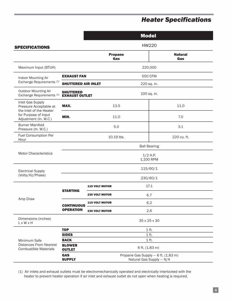
SPECIFICATIONS HW220
Propane NaturalGas Gas
Maximum Input (BTUH) 220,000
EXHAUST FAN 550 CFM
SHUTTERED AIR INLET 220 sq. in.
100 sq. in.
MAX. 13.5 11.0
MIN. 11.0 7.0
5.0 3.1
10.19 lbs. 220 cu. ft.
Ball Bearing
1/2 H.P.1,100 RPM
115/60/1
230/60/1
17.1
6.7
6.2
2.6
35 x 25 x 30
TOP 1 ft.SIDES 1 ft.BACK 1 ft.BLOWEROUTLET
GAS Propane Gas Supply — 6 ft. (1.83 m)SUPPLY Natural Gas Supply — N/A
(1) Air inlets and exhaust outlets must be electromechanically operated and electrically interlocked with theheater to prevent heater operation if air inlet and exhaust outlet do not open when heating is required.
Model
Indoor Mounting AirExchange Requirements (1)
Burner ManifoldPressure (In. W.C.)
Electrical Supply(Volts/Hz/Phase)
Amp Draw
Dimensions (inches)L x W x H
Minimum SafeDistances From NearestCombustible Materials
STARTING
CONTINUOUSOPERATION
Motor Characteristics
Fuel Consumption PerHour
Inlet Gas Supply Pressure Acceptable atthe Inlet of the Heater for Purpose of InputAdjustment (In. W.C.)
6 ft. (1.83 m)
Outdoor Mounting AirExchange Requirements (1)
SHUTTERED EXHAUST OUTLET
115 VOLT MOTOR
230 VOLT MOTOR
115 VOLT MOTOR
230 VOLT MOTOR
55
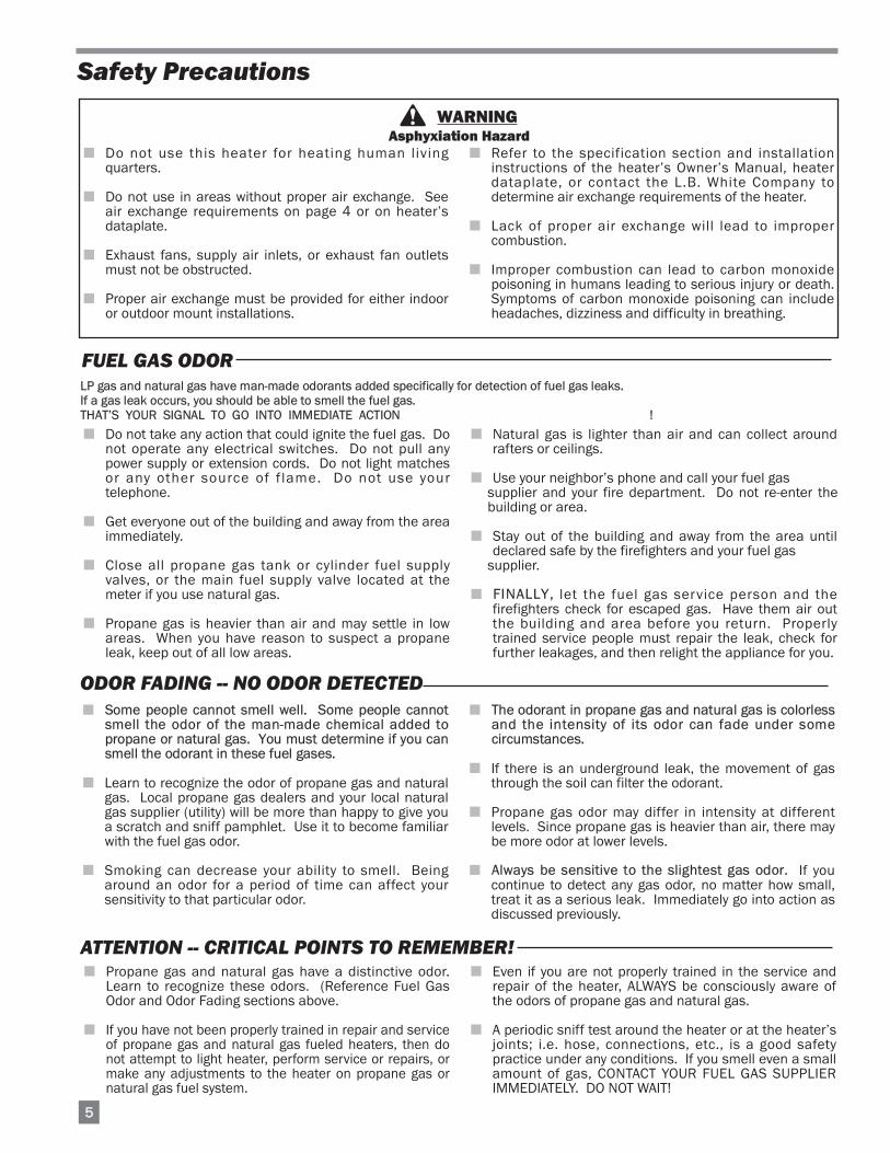
LP gas and natural gas have man-made odorants added specifically for detection of fuel gas leaks.If a gas leak occurs, you should be able to smell the fuel gas.THAT’S YOUR SIGNAL TO GO INTO IMMEDIATE ACTION !
■ Do not take any action that could ignite the fuel gas. Donot operate any electrical switches. Do not pull anypower supply or extension cords. Do not light matchesor any other source of f lame. Do not use yourtelephone.
■ Get everyone out of the building and away from the areaimmediately.
■ Close all propane gas tank or cylinder fuel supplyvalves, or the main fuel supply valve located at themeter if you use natural gas.
■ Propane gas is heavier than air and may settle in lowareas. When you have reason to suspect a propaneleak, keep out of all low areas.
■ Natural gas is lighter than air and can collect aroundrafters or ceilings.
■ Use your neighbor’s phone and call your fuel gas supplier and your fire department. Do not re-enter thebuilding or area.
■ Stay out of the building and away from the area untildeclared safe by the firefighters and your fuel gas
supplier.
■ FINALLY, let the fuel gas service person and thefirefighters check for escaped gas. Have them air outthe building and area before you return. Properlytrained service people must repair the leak, check forfurther leakages, and then relight the appliance for you.
WARNING
■ Do not use this heater for heating human livingquarters.
■ Do not use in areas without proper air exchange. Seeair exchange requirements on page 4 or on heater’sdataplate.
■ Exhaust fans, supply air inlets, or exhaust fan outletsmust not be obstructed.
■ Proper air exchange must be provided for either indooror outdoor mount installations.
■ Refer to the specification section and installationinstructions of the heater’s Owner’s Manual, heaterdataplate, or contact the L.B. White Company todetermine air exchange requirements of the heater.
■ Lack of proper air exchange will lead to impropercombustion.
■ Improper combustion can lead to carbon monoxidepoisoning in humans leading to serious injury or death.Symptoms of carbon monoxide poisoning can includeheadaches, dizziness and difficulty in breathing.
Asphyxiation Hazard
■ Some people cannot smell well. Some people cannotsmell the odor of the man-made chemical added topropane or natural gas. You must determine if you cansmell the odorant in these fuel gases.
■ Learn to recognize the odor of propane gas and naturalgas. Local propane gas dealers and your local naturalgas supplier (utility) will be more than happy to give youa scratch and sniff pamphlet. Use it to become familiarwith the fuel gas odor.
■ Smoking can decrease your ability to smell. Beingaround an odor for a period of time can affect yoursensitivity to that particular odor.
■ The odorant in propane gas and natural gas is colorlessand the intensity of its odor can fade under somecircumstances.
■ If there is an underground leak, the movement of gasthrough the soil can filter the odorant.
■ Propane gas odor may differ in intensity at differentlevels. Since propane gas is heavier than air, there maybe more odor at lower levels.
■ Always be sensitive to the slightest gas odor. If youcontinue to detect any gas odor, no matter how small,treat it as a serious leak. Immediately go into action asdiscussed previously.
Safety Precautions
FUEL GAS ODOR
ODOR FADING -- NO ODOR DETECTED
ATTENTION -- CRITICAL POINTS TO REMEMBER!
■ Propane gas and natural gas have a distinctive odor.Learn to recognize these odors. (Reference Fuel GasOdor and Odor Fading sections above.
■ If you have not been properly trained in repair and serviceof propane gas and natural gas fueled heaters, then donot attempt to light heater, perform service or repairs, ormake any adjustments to the heater on propane gas ornatural gas fuel system.
■ Even if you are not properly trained in the service andrepair of the heater, ALWAYS be consciously aware ofthe odors of propane gas and natural gas.
■ A periodic sniff test around the heater or at the heater’sjoints; i.e. hose, connections, etc., is a good safetypractice under any conditions. If you smell even a smallamount of gas, CONTACT YOUR FUEL GAS SUPPLIERIMMEDIATELY. DO NOT WAIT!

1. Do not attempt to install, repair, or service this heateror the gas supply line unless you have continuingexpert training and knowledge of gas heaters.
Qualifications for service and installation of thisequipment are as follows:
a. To be a qualified gas heater service person, youmust have sufficient training and experience tohandle all aspects of gas-fired heater installation,service and repair. This includes the task ofinstallation, troubleshooting, replacement ofdefective parts and testing of the heater. Youmust be able to place the heater into a continuingsafe and normal operating condition. You mustcompletely familiarize yourself with each modelheater by reading and complying with the safetyinstructions, labels, Owner’s Manual, etc., that isprovided with each heater.
b. To be a qualified gas installation person, you musthave sufficient training and experience to handleall aspects of installing, repairing and altering gaslines, including selecting and installing the properequipment, and selecting proper pipe and tanksize to be used. This must be done in accordancewith all local, state and national codes as well asthe manufacturer’s requirements.
2. All installations and applications of L.B. White heatersmust meet all relevant local, state and nationalcodes. Included are L.P. gas, natural gas, electrical,and safety codes. Your local fuel gas supplier, a locallicensed electrician, the local fire department orsimilar government agencies, or your insurance agentcan help you determine code requirements.Refer tothe following:
-- ANSI/NFPA 58, latest edition, Standard forStorage and Handling of Liquefied PetroleumGas and/or
-- ANSI Z223.1/NFPA 54, National Fuel GasCode
-- ANSI/NFPA 70, National Electrical Code.
3. Do not move, handle, or service heater while inoperation or connected to a power or fuel supply.
4. This heater may be installed in areas subject towashdown. This heater may only be washed on theexternal case assembly—see Cleaning Instructions.Do not wash the interior of the heater. Use onlycompressed air, soft brush or dry cloth to clean theinterior of the heater and it’s components. Afterexternal washdown, do not operate this heater until itis completely dry. In any event, do not operate theheater for at least one hour after external washdown.
5. For safety, this heater is equipped with a manualreset high-limit switch and an air proving switch.Never operate this heater with any safety device thathas been bypassed. Do not operate this heaterunless all of these features are fully functioning.
6. Do not operate the heater with its door open.
7. Do not locate fuel gas containers or fuel supplyhoses anywhere near the blower outlet of the heater.
8. Do not block air intakes or discharge outlets of theappliance. Doing so may cause improper combustionor damage to heater components leading to propertydamage or plant loss.
9. The hose assembly shall be visually inspected on anannual basis. If it is evident there is excessiveabrasion or wear, or if the hose is cut, it must bereplaced prior to the heater being put into operation.The hose assembly shall be protected from animals,building materials, and contact with hot surfacesduring use. The hose assembly shall be thatspecified by the manufacturer. See parts list.
10. Check for gas leaks and proper function upon heaterinstallation, before building repopulation or whenrelocating.
11. This heater should be inspected for proper operationby a qualif ied service person before buildingrepopulation and at least annually.
12. Always turn off the gas supply to the heater if theheater is not going to be used.
13. Heaters requiring 230 volts electrical supply musthave electrical wiring consisting of two hot leads, aneutral lead, and a ground lead. All GreenGroheaters, regardless of voltage, must be properlyconnected to a grounded electrical supply. Failureto use a grounded electrical supply can result inelectrical shock, serious injury, or death.
14. Direct ignition heaters will make up to three trials forignition. If ignition is not achieved, the control systemwill lock out the gas control valve. If gas is smelledafter system lock out has occurred, immediately closeall fuel supply valves. Do not relight until you are surethat all gas that may have accumulated has clearedaway. In any event, do not relight for at least 5minutes.
15. In a hanging type installation, rigid pipe or coppertubing coupled directly to the heater may cause gasleaks during movement, and therefore must not beused. Use only gas hose assemblies that are ratedand approved for L.P. gas and natural gas in ahanging type of installation.
16. Installations not using the gas hose supplied with thisappliance must connect dimensionally usingAmerican National Standard Wrought Steel andWrought Iron Pipe B36/10-1970. (Aluminum pipingor tubing shall not be used.) Copper tubing whenused for conveying natural gas, shall be internallytinned or equivalently treated to resist sulphur.
66
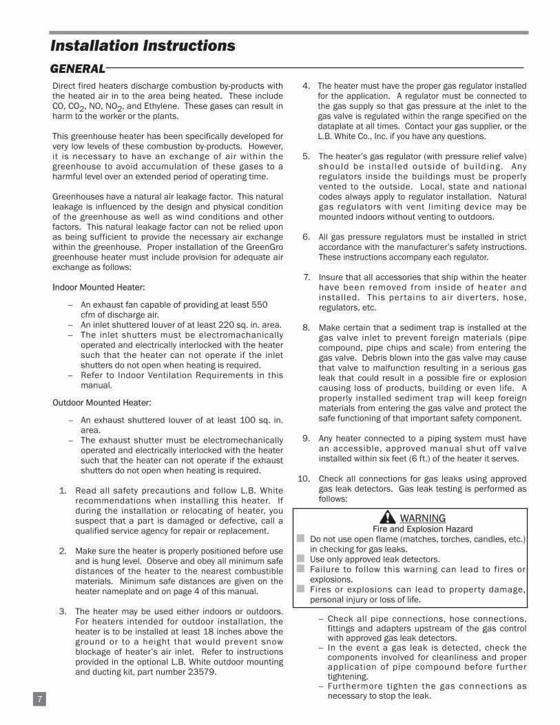
Direct fired heaters discharge combustion by-products withthe heated air in to the area being heated. These includeCO, CO2, NO, NO2, and Ethylene. These gases can result inharm to the worker or the plants.
This greenhouse heater has been specifically developed forvery low levels of these combustion by-products. However,it is necessary to have an exchange of air within thegreenhouse to avoid accumulation of these gases to aharmful level over an extended period of operating time.
Greenhouses have a natural air leakage factor. This naturalleakage is influenced by the design and physical conditionof the greenhouse as well as wind conditions and otherfactors. This natural leakage factor can not be relied uponas being sufficient to provide the necessary air exchangewithin the greenhouse. Proper installation of the GreenGrogreenhouse heater must include provision for adequate airexchange as follows:
IIndoor Mounted Heater:
-- An exhaust fan capable of providing at least 550 cfm of discharge air.
-- An inlet shuttered louver of at least 220 sq. in. area.-- The inlet shutters must be electromachanically
operated and electrically interlocked with the heatersuch that the heater can not operate if the inletshutters do not open when heating is required.
-- Refer to Indoor Ventilation Requirements in thismanual.
Outdoor Mounted Heater:
-- An exhaust shuttered louver of at least 100 sq. in.area.
-- The exhaust shutter must be electromechanicallyoperated and electrically interlocked with the heatersuch that the heater can not operate if the exhaustshutters do not open when heating is required.
1. Read all safety precautions and follow L.B. Whiterecommendations when installing this heater. Ifduring the installation or relocating of heater, yoususpect that a part is damaged or defective, call aqualified service agency for repair or replacement.
2. Make sure the heater is properly positioned before useand is hung level. Observe and obey all minimum safedistances of the heater to the nearest combustiblematerials. Minimum safe distances are given on theheater nameplate and on page 4 of this manual.
3. The heater may be used either indoors or outdoors.For heaters intended for outdoor installation, theheater is to be installed at least 18 inches above theground or to a height that would prevent snowblockage of heater’s air inlet. Refer to instructionsprovided in the optional L.B. White outdoor mountingand ducting kit, part number 23579.
4. The heater must have the proper gas regulator installedfor the application. A regulator must be connected tothe gas supply so that gas pressure at the inlet to thegas valve is regulated within the range specified on thedataplate at all times. Contact your gas supplier, or theL.B. White Co., Inc. if you have any questions.
5. The heater’s gas regulator (with pressure relief valve)should be instal led outside of bui lding. Anyregulators inside the buildings must be properlyvented to the outside. Local, state and nationalcodes always apply to regulator installation. Naturalgas regulators with vent limiting device may bemounted indoors without venting to outdoors.
6. All gas pressure regulators must be installed in strictaccordance with the manufacturer’s safety instructions.These instructions accompany each regulator.
7. Insure that all accessories that ship within the heaterhave been removed from inside of heater andinstalled. This pertains to air diverters, hose,regulators, etc.
8. Make certain that a sediment trap is installed at thegas valve inlet to prevent foreign materials (pipecompound, pipe chips and scale) from entering thegas valve. Debris blown into the gas valve may causethat valve to malfunction resulting in a serious gasleak that could result in a possible fire or explosioncausing loss of products, building or even life. Aproperly installed sediment trap will keep foreignmaterials from entering the gas valve and protect thesafe functioning of that important safety component.
9. Any heater connected to a piping system must havean accessible, approved manual shut off valveinstalled within six feet (6 ft.) of the heater it serves.
10. Check all connections for gas leaks using approvedgas leak detectors. Gas leak testing is performed asfollows:
-- Check all pipe connections, hose connections,fittings and adapters upstream of the gas controlwith approved gas leak detectors.
-- In the event a gas leak is detected, check thecomponents involved for cleanliness and properapplication of pipe compound before furthertightening.
-- Fur thermore tighten the gas connections asnecessary to stop the leak.7
Installation Instructions
GENERAL
WARNINGFire and Explosion Hazard
■ Do not use open flame (matches, torches, candles, etc.)in checking for gas leaks.
■ Use only approved leak detectors. ■ Failure to follow this warning can lead to fires or
explosions.■ Fires or explosions can lead to property damage,
personal injury or loss of life.

-- After all connections are checked and any leaksare stopped, turn on the main burner.
-- Stand clear while the main burner ignites toprevent injury caused from hidden leaks that couldcause flashback.
-- With the main burner in operation, check allconnections, hose connections, fittings and jointsas well as the gas control valve inlet and outletconnections with approved gas leak detectors.
-- If a leak is detected, check the componentsinvolved for cleanliness in the thread areas andproper application of pipe compound before furthertightening.
-- Tighten the gas connection as necessary to stopthe leak.
-- If necessary, replace the parts or componentsinvolved if the leak cannot be stopped.
-- Ensure all gas leaks have been identified andrepaired before proceeding.
11. A qualified service agency must check for properoperating gas pressure upon installation of theheater.
12. Light according to instructions on heater or withinowner's manual.
13. It is extremely important to use the proper size andtype of gas supply line to assure proper functioning ofthe heater. Contact your fuel gas supplier for properline sizing and installation.
14. This heater can be configured for use with either L.P.gas vapor withdrawal or natural gas. Consult the
dataplate for the gas configuration of the specificheater. Do not use the heater in an L.P. gas liquidwithdrawal system or application. If you are in doubt,contact the L.B. White Co., Inc.
15. Eventually, like all electrical/mechanical devices, thethermostat can fail. Thermostat failure may result ineither an underheating or overheating condition whichmay damage or ki l l plants. Plants should beprotected by a separate back-up control system thatlimits high and low temperatures and also activatesappropriate alarms.
16. Take time to understand how to operate and maintainthe heater by using this Owner’s Manual. Make sureyou know how to shut off the gas supply to thebuilding and also to the individual heater. Contactyour fuel gas supplier if you have any questions.
17. Any defects found in performing any of the service ormaintenance procedures must be eliminated anddefective parts replaced immediately. The heatermust be retested by properly qualif ied servicepersonnel before placing the heater back into use.
18. Do not exceed input rating stamped on the dataplateof the heater. Do not exceed the burner manifoldpressure stated on the dataplate. Do not use anorifice size different than specified for the specificinput rating of this heater, fuel type configuration andaltitude.
1. The air discharge diverter duct provides improveddirectional air flow and greater heat throw, beneficialin heating long houses. Use the duct oonly on indoormounted heaters. Do not use the diverter when theheater is mounted outside the green house. Thediverter duct requires hand forming prior to assembly.Make 90 degree bends utilizing the performationsprovided. Assemble as shown in Fig. 1.
FIG. 1
2. Remove the upper and lower screws at both sides ofthe blower outlet, and the two screws at outlet top.
3. Install flanges as shown in Fig. 2, using the samescrews. Tighten the screws securely.
4. Position the diverter over the flanges. Align holes indiverter to flange holes and to vacant holes at topand bottom of blower outlet.
5. Fasten the diverter to the flanges with the screwsprovided. See Fig. 3.
FIG. 2 FIG. 3
AIR DISCHARGE DIVERTER DUCTPart Number 25977
(Accessory)
UPPERSCREW
LOWERSCREW
SCREWS REMOVED AT OUTLET TOP
PERFORATIONS
PERFORATIONS
VANESMUST BEDIRECTED DOWNWARD
8
SCREWSFROM KIT
INDOOR VENTILATION REQUIREMENTS
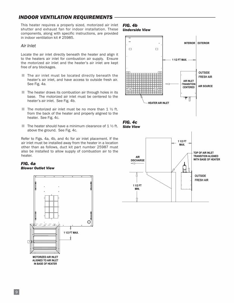
This heater requires a properly sized, motorized air inletshutter and exhaust fan for indoor installation. Thesecomponents, along with specific instructions, are providedin indoor ventilation kit # 25985.
Air Inlet
Locate the air inlet directly beneath the heater and align itto the heaters air inlet for combustion air supply. Ensurethe motorized air inlet and the heater’s air inlet are keptfree of any blockages.
■ The air inlet must be located directly beneath theheater’s air inlet, and have access to outside fresh air.See Fig. 4a.
■ The heater draws its combustion air through holes in itsbase. The motorized air inlet must be centered to theheater’s air inlet. See Fig. 4b.
■ The motorized air inlet must be no more than 1 ½ ft.from the back of the heater and properly aligned to theheater. See Fig. 4c.
■ The heater should have a minimum clearance of 1 ½ ft.above the ground. See Fig. 4c.
Refer to Figs. 4a, 4b, and 4c for air inlet placement. If theair inlet must be installed away from the heater in a locationother than as follows, duct kit part number 25987 mustalso be installed to allow supply of combustion air to theheater.
FIG. 4aBlower Outlet View
FIG. 4bUnderside View
FIG. 4cSide View
1 1/2 FT MAX.
MOTORIZED AIR INLETALIGNED TO AIR INLET
IN BASE OF HEATER
HEATER AIR INLET
AIR INLETTRANSITIONCENTERED
INTERIOR EXTERIOR
1 1/2 FT MAX.
OUTSIDEAIR SOURCE
1 1/2 FTMAX.
TOP OF AIR INLETTRANSITION ALIGNEDWITH BASE OF HEATER
OUTSIDEAIR SOURCE
AIRDISCHARGE
1 1/2 FTMIN.
OUTSIDEFRESH AIR
OUTSIDE FRESH AIR
9

As shipped, the heater is configured for mounting to anoptional mounting bracket kit, part number 23652, which isinstalled on freestanding supports or mounted directly tothe structure’s wall. Separate installation instructionsaccompany the kit.
The heater may also be suspended by chain to thegreenhouse’s overhead structure by using an optional chainhanging kit, part number 07802. Refer to the followinginstructions.and illustrations.
1. Remove case top hole plugs. See Fig. 6.
FIG. 6
2. Assemble eyebolts and chain according to theillustration and tighten all eyebolts securely.
FIG. 7
3. Ensure the heater is securely fastened to overheadsupports and is hanging level. (Check crosswise andlengthwise.)
4. See Fig. 5 for typical indoor installation. In anyinstallation, consideration must be given to makingsure the heater is located away from the peopleentering or exiting the greenhouse so they cannotaccidentally knock the heater or tamper with theheater and its gas supply line in any way. Additionally,the heater must be located so that it does not blockthe normal entryway or exit of the building. Observeand obey minimum clearance distances tocombustible materials as stated in the specificationsection of this owner’s manual and on the heater’sdataplate.
EExhaust Fan
The exhaust fan must be located at an upper area of theend wall opposite from the heater, preferably in an areahigher than the heater’s discharge. See Fig. 5. The fandoes not need to be directly in line to the heater. Ensure theexhaust fan is kept free of blockage.
FIG. 5
EYE BOLT
NUT 1/4-20
FLAT WASHER
FLAT WASHER
NUT 1/4-20
CHAIN
HEATER TOP
ENTRY / EXIT
AIR INLET LOCATEDDIRECTLY BENEATH HEATER
AIR INLET.
AIR FLOW
EXHAUST FAN IN UPPER AREA OFGREENHOUSE
CHAIN OR CABLE
10
HANGING THE HEATER
1. TTo Connect the Series Tap Plug Thermostat Kit:
a. Connect the power cord of the heater to thefemale side of the plug on the end of thethermostat cord.
b. Plug the male side of the series tap plug on thethermostat cord into a three-wire (grounded)electrical outlet within the building.
2. To Connect the Direct Wired Thermostat Kit to theControl Box on the Heater:
a. The installation and wiring of a thermostat mustbe done by an electrician or someone properlyqualified.
b. The thermostat may use 18 gauge, 2 wire cord tohandle the low voltage being supplied to thethermostat from the transformer.
c. Fol low al l instructions provided with thethermostat kit.
d. The heater must be tested for proper operationafter the thermostat has been connected.
WARNINGElectrical Shock Hazard
■ Disconnect the electrical supply before connecting thethermostat to the heater.
■ Failure to follow this warning can result in electricalshock, leading to personal injury or death.
11
THERMOSTAT INSTALLATION
MANUAL SHUT-OFF VALVE, HOSEAND REGULATOR ASSEMBLY
REGULATOR
NIPPLE
VALVE, MANUALSHUT-OFF
GAS HOSE
ADAPTER
SEDIMENT TRAPTO CONTROL
VALVE INLET
REGULATOR VENT
GAS
FLO
W
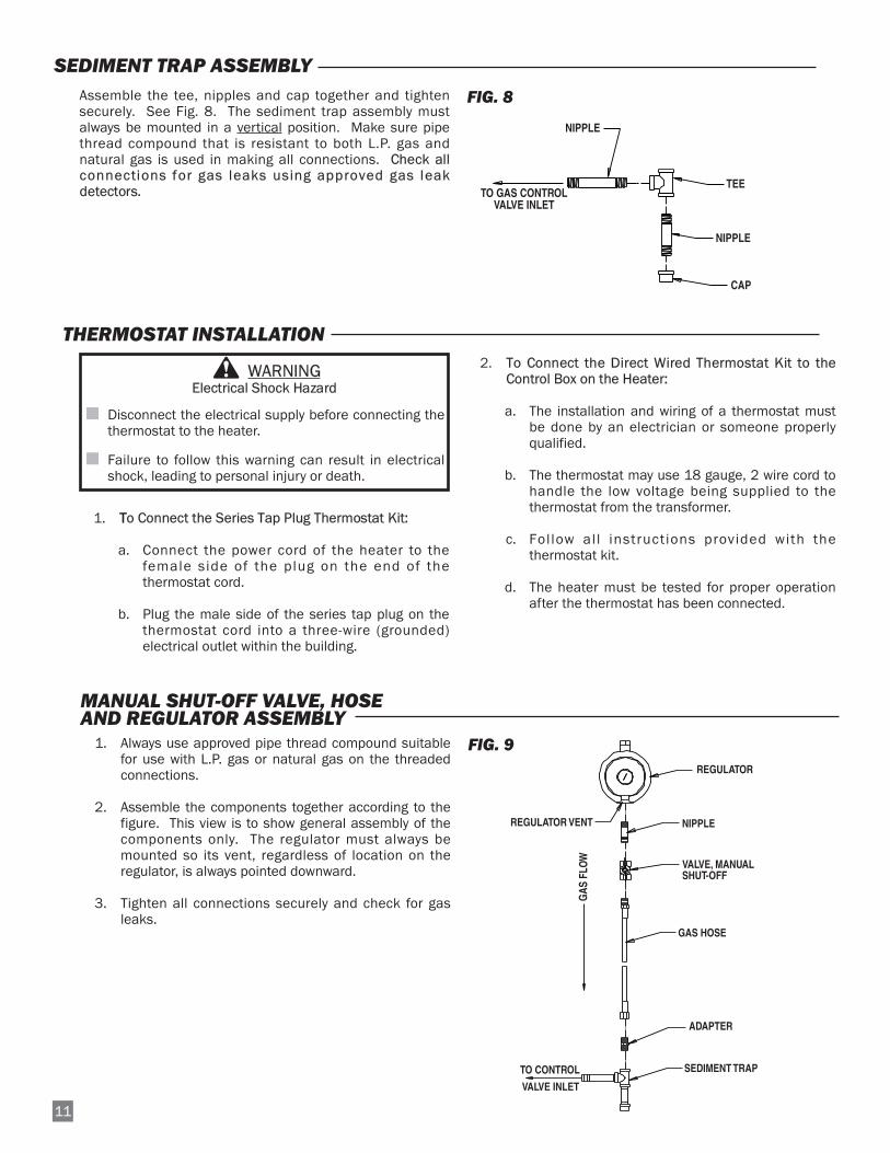
1. Always use approved pipe thread compound suitablefor use with L.P. gas or natural gas on the threadedconnections.
2. Assemble the components together according to thefigure. This view is to show general assembly of thecomponents only. The regulator must always bemounted so its vent, regardless of location on theregulator, is always pointed downward.
3. Tighten all connections securely and check for gasleaks.
FIG. 9
Assemble the tee, nipples and cap together and tightensecurely. See Fig. 8. The sediment trap assembly mustalways be mounted in a vertical position. Make sure pipethread compound that is resistant to both L.P. gas andnatural gas is used in making all connections. Check allconnections for gas leaks using approved gas leakdetectors.
FIG. 8
SEDIMENT TRAP ASSEMBLY
NIPPLEHOSE ADAPTER
TEE
NIPPLE
CAP
TO GAS CONTROLVALVE INLET

Follow steps 1 - 6 on initial start-up after heater installationby a qualified gas heater service person. For normal start-up, simply turn thermostat above room temperature. Theheater will start.
1. Open all manual fuel supply valves and check for gasleaks using approved leak detectors. The gas controlvalve on the heater has a manual shut-off featureincorporated into the valve assembly. Make sure theindicator on the valve is turned to the on position.See Fig. 10.
FIG. 10
2. Connect the electrical cord to an approved electricaloutlet.
3. Set the thermostat (if supplied) to desired roomtemperature.
4. This heater includes a hot surface ignition (HSI)control module for purposes of controlling the timingof the ignition process of the heater as well asmonitoring of the safety functions. The HSI module iscontained within the control enclosure. When the heater receives a call for heat, the red lightemitting diode (LED) on the ignition control will comeon. This LED indicates the status of the heater. The
LED is visible through the plastic window of thecontrol box. A constant light from the LED is anindicator that the heater is functioning correctly.
5. On a call for heat, the motor will start and run for five(5) seconds and then stop. This pre-purge is a safetyfeature and a normal operational characteristic priorto ignition taking place. After the motor has stopped,the igniter will heat up (approximately 17 seconds).After igniter warm up time has been achieved, themotor will start again and shortly thereafter ignitionwill occur.
NOTE: It is normal for air to be trapped in the gashose on new installations. The heater mayattempt more than one trial for ignition beforethe air is finally purged from the line andignition takes place.
6. The HSI control will make up to three trials forignition. Each trial for ignition will take approximately20 seconds. The first two trials for ignition will occurwithin 40 seconds if ignition is not achieved. A 15minute wait period will then begin after the secondtrial for ignition has taken place. After the 15 minutetime has passed, the third and final trial for ignitionwill take place. If ignition is not achieved at this finaltrial, the system will lock out, and a three flashpattern will be indicated by the LED.
7. Do not exceed input rating stamped on nameplate ormanufacturer’s recommended burner orifice pressurefor size orifice(s) used. Make certain that the primaryair supply to main burner is open and free of dust, dirtand debris for complete, proper combustion.
If the heater is to be shut down for cleaning, maintenance orrepair, follow steps 1 - 5. Otherwise, simply turn thermostatto off or no heat for standard shut down.
1. Close all manual fuel supply valves.
2. With the heater lit, allow heater to burn off excessfuel in gas supply hose.
3. Turn the indicator on the gas control to off.
4. Turn thermostat to off or no heat position.
5. Disconnect the heater from the electrical supply.
112
Start-Up Instructions
Shut-Down Instructions
ON
OFF

113
1. Before cleaning, shut off all gas supply valves anddisconnect electrical supply.
2. At least once a year give the heater a thoroughcleaning, preferably before the beginning of the fallheating season. At that time, remove the fan andmotor assembly and brush or blow off the fan wheel.Additionally, ensure the burner casting and orifice arefree of dust accumulation, insect nests, webs, etc.
WARNINGDo not use a pressure washer, water, or liquid cleaningsolution on any heater components. Use of a pressurewasher, water, or liquid cleaning solution on the controlcomponents can cause severe personal injury orproperty damage due to water and/or liquids:
■ In electrical components, and wires causing electricalshock or equipment failure.
■ On gas control valves causing corrosion which canresult in gas leaks and fire or explosion from the leak.
Clean all internal components of the heater with pressurized air, a dry brush, or a dry cloth.
Cleaning Instructions
WARNINGFire, Burn, and Explosion Hazard
■ This heater contains electrical and mechanical components in the gas management, and safety systems.
■ Such components may become inoperative or fail due to dust, dirt, wear and aging.
■ Periodic cleaning and inspection as well as proper maintenance are essential to avoid serious injury or propertydamage.
1. The area surrounding the heater shall be kept clearand free from combustible materials, gasoline, andother flammable vapors and liquids.
2. Have your gas supplier check all gas piping annuallyfor leaks or restrictions in gas lines.
3. Regulators must be periodically inspected to makesure the regulator vents are not blocked. Debris,insects, insect nests, snow, or ice on a regulator canblock vents and cause excess pressure at the heater.
4. Regulators can wear out and function improperly.Have your gas supplier check the date codes on allregulators installed and check delivery pressures tothe heater to make sure that the regulator is reliable.
5. Check all wiring associated terminals and electricalcomponents within the heater for corrosion, frayed orcut insulation, tight connections, etc. Repair orreplace as necessary.
6. Review all heater markings (i.e. wiring diagram,warnings, start-up, shut-down, troubleshooting, etc.)at the time of maintenance for legibility. Make surenone are cut, torn, or otherwise damaged. Anydamaged markings must be replaced immediately bycontacting the L.B. White Co., Inc. Dataplates, start-up and shut-down instructions and warnings areavailable at no cost. A nominal charge will be appliedfor wiring diagrams.
Maintenance Instructions

114
1. Remove the motor mounting plate screws and pullthe fan and motor assembly from the housing.
2. Loosen the square head set screw(s) on the fanwheel.
3. Pull the fan wheel from the motor shaft. Use a wheelpuller if necessary.
4. Remove the four (4) nuts securing the motor to themounting plate.
NOTES:a. Fan wheel to motor mount plate spacing must beadjusted to the clearance specified in the tablebelow before tightening the fan wheel to themotor shaft.
b. Make sure that set screw(s) of the fan are on theflats of motor shaft when tightening.
FIG. 11
MOTOR AND FAN WHEEL ASSEMBLY
MOTOR MOUNT PLATE FAN WHEEL
CLEARANCEMOTOR 1/8 IN.
Service InstructionsGENERAL
1. Close the fuel supply valve to the heater anddisconnect the electrical supply before servicingunless necessary for your service procedure.
2. Open end panels for access to heater components.
3 Disconnect the appropriate electrical leads for thecomponent being replaced.
4. The thermostat, and high limt switch can be tested byjumpering the suspect part out of the electricalcircuit.:
-- Reconnect the electrical supply and open fuelsupply valves.
-- If the heater lights, the component is defectiveand must be replaced.
-- Do not operate the heater with the componentjumpered. Replace the part immediately.
-- An alternate method for checking thecomponents is to perform a continuity check.
5. Do not jumper the air proving switch. If jumpered, theignition control will not allow heater operation. Testthe air proving switch for continuity. If defective,replace the switch
6. For reassembly, reverse the respective serviceprocedure. Ensure gas connections are tightenedsecurely.
7. After servicing, start the heater to ensure properoperation. Check for gas leaks with approved leakdetectors.
8. Clean the heater’s orifice with compressed air or asoft, dry rag. Do not use files, drills, broaches, etc. toclean the orifice. Doing so may enlarge the hole,causing combustion or ignition problems. Replacethe orifice if it cannot be cleaned properly.
WARNINGFire and Explosion Hazard
■ Do not disassemble or attempt to repair anycomponent part of the heater, including regulatorsand gas hoses.
■ All components must be replaced if defects arefound.
■ Failure to follow this warning will result in gas leaks.
■ Gas leaks cause fire or explosions, leading toproperty damage, injury, or death.
WARNINGBurn Hazard
■ Heater surfaces are hot for a period of time after theheater has been shut down.
■ Allow the heater to cool before performing service,maintenance, or cleaning.
■ Failure to follow this warning will result in burnscausing injury.

115
AIR PROVING SWITCH
SWITCH W/ PADDLE
LEADS
NUTS
PADDLE
OBLONG HOLE
HOUSING SIDE PANEL
1. Remove two sheet metal screws holding air provingswitch assembly to blower housing. Removeassembly by turning switch assembly 90 degrees sothe switch paddle can be pulled through oblong holeon side of fan housing. See Fig. 12.
3. Disconnect the leads from the air proving switch.
4. When installing replacement switch, use care in notbending the switch arm, otherwise ignition problemsmay occur. Replacement includes mounting bracket.
FIG. 12
The high limit switch should be tested a minimum of onceper year when the heater is given a thorough cleaning.
1. Remove the high l imit switch from the heatchamber.
2. Holding the switch by one of its mounting legs orelectrical terminals, apply a small flame only to thesensing surface on the back of the switch. Becareful not to melt the plastic housing of the switchwhen conducting this test.
3. Within a minute, you should hear a pop comingfrom the switch, which indicates the contacts of theswitch have opened.
4. Allow the switch cool down for about a minutebefore firmly pressing the red reset button on theswitch.
5. Check for electrical continuity across the switchterminals to make sure the contacts have closed.
6. Reinstall the switch back into the heater.
FIG. 13
TESTING THE MANUAL RESET HIGH LIMIT SWITCH
RESET BUTTON
SENSINGSURFACE
TERMINAL
FLAMEMOUNTINGLEG
WARNINGFire Hazard
■ Do not operate the heater with the high limit switchbypassed.
■ Operating the heater with a bypassed high limit switchmay lead to overheating, possibly resulting in a fire,with subsequent damage to the heater, buildingdamage, or loss of livestock.
1. Remove the following-- Hose and sediment trap from inlet of gas valve-- Screws securing valve bracket to heater base. -- Burner bolt from underside of base.-- Screws and spacers securing burner casting to
heat chamber.
2. Remove control valve with burner from heater. Rotatethe valve/manifold assembly as necessary so orificeand orifice block can exit the burner casting venturiport..
3. Replace components as needed.
FIG. 14
BURNER ORIFICE and GAS CONTROL VALVE
ORIFICEBLOCK
BURNERORIFICE
GAS CONTROLVALVE
OUTLET PRESSURE T
INLET PRESSURE TAP
ON
OFF
ATTENTION
■ The following explains a typical procedure to be followedin checking gas pressures.
■ The gas pressures will vary depending upon fuel type.
■ Consult the dataplate on the heater or page 4 in thismanual for specific pressures to be used in conjunctionwith this procedure.
■ Gas pressure measured at the inlet to the gas valve isInlet Pressure and gas pressure measured at the outletof the gas valve is Burner Manifold Pressure.
AA. Preparation
1. Obtain two pressure gauges capable of reading up to35 in. W.C.
2. Disconnect the heater from the electrical supply andclose the fuel supply valve to the heater inlet.
3. Open the burner access panel.
4. Brush or blow off any dust and dirt on or in the vicinityof the gas control valve.
B. Gauge Installation
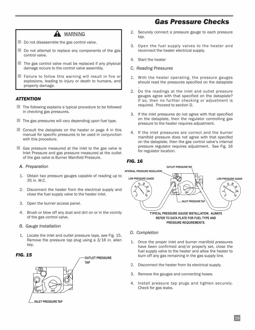
1. Locate the inlet and outlet pressure taps, see Fig. 15.Remove the pressure tap plug using a 3/16 in. allenkey.
FIG. 15
2. Securely connect a pressure gauge to each pressuretap.
3. Open the fuel supply valves to the heater andreconnect the heater electrical supply.
4. Start the heater
C. Reading Pressures
1. With the heater operating, the pressure gaugesshould read the pressures specified on the dataplate.
2. Do the readings at the inlet and outlet pressuregauges agree with that specified on the dataplate?If so, then no further checking or adjustment isrequired. Proceed to section D.
3. If the inlet pressures do not agree with that specifiedon the dataplate, then the regulator controlling gaspressure to the heater requires adjustment.
4. If the inlet pressures are correct and the burnermanifold pressure does not agree with that specifedon the dataplate, then the gas control valve’s internalpressure regulator requires adjustment. See Fig. 16for regulator location.
FIG. 16
D. Completion
1. Once the proper inlet and burner manifold pressureshave been confirmed and/or properly set, close thefuel supply valve to the heater and allow the heater toburn off any gas remaining in the gas supply line.
2. Disconnect the heater from its electrical supply.
3. Remove the gauges and connecting hoses.
4. Install pressure tap plugs and tighten securely.Check for gas leaks.
Gas Pressure Checks
WARNING
■ Do not disassemble the gas control valve.
■ Do not attempt to replace any components of the gascontrol valve.
■ The gas control valve must be replaced if any physicaldamage occurs to the control valve assembly.
■ Failure to follow this warning will result in fire orexplosions, leading to injury or death to humans, andproperty damage.
16
LOW PRESSURE GUAGE
OUTLET PRESSURE TAP
INLET PRESSURE TAP
LOW PRESSURE GUAGE
EXAMPLE SHOWS PRESSURE FOR PROPANE GASALWAYS REFER TO PRESSURE ON DATAPLATE
OFF
ON
INTERNAL PRESSURE REGULATOR
OUTLET PRESSURE TAP
TYPICAL PRESSURE GAUGE INSTALLATION. ALWAYSREFER TO DATA PLATE FOR FUEL TYPE AND
PRESSURE REQUIREMENTS.

117
1. Remove the sensor from its mounting bracket. Cleanthe sensor’s rod with emery cloth or steel wool tobuildup of dirt to help maintain proper flame sense.See Fig. 17.
2. Check the flame sensor’s insulative base for anycracks. If cracks are found, replace the sensor.
FIG. 17
■ For proper flame sense operation, the flame sensor tipmust be properly positioned within the burner flame.See Fig. 18.
FIG. 18
FLAME SENSOR
IGNITER
1. Disconnect the plastic male and female plugslocated at the end of the igniter leads. See Fig. 17.
2. Loosen the screw securing the igniter shield and theigniter to the mounting bracket. Remove the igniterand shield.
3. Ensure the igniter is located so the its lip on backside of igniter is resting on the edge of the mountingbracket and the mounting hole in the igniter alignswith the mounting hole in the bracket.
4. Slide the igniter shield over the igniter so hole inshield aligns with hole in igniter and bracket.
■ Handle the igniter by its ceramic base, or by its leads.
■ Center the igniter shield over the igniter element,making sure the shield does not touch the igniterelement, otherwise igniter damage will occur when theigniter is energized.
■ Do not over tighten the igniter mounting screw.Overtightening may crack the base of the igniter,leading to premature failure.
IGNITER
SHIELD
SCREW
WASHER
MALE CONNECTOR FEMALE CONNECTOR
SCREW
BRACKET
BURNER
SENSOR
BURNERFLAME
BURNERCASTING
FLAME SENSOR
3/8 TO 1/2 IN.1/2 in. to 3/4 in.
Troubleshooting Instructions
READ THIS ENTIRE SECTION BEFORE BEGINNING TOTROUBLESHOOT PROBLEMS.
The
fol lowing troubleshooting guide provides systematicprocedures for isolating equipment problems. This guide isintended for use by a QUALIFIED GAS HEATER SERVICEPERSON. DO NOT ATTEMPT TO SERVICE THESE HEATERSUNLESS YOU HAVE BEEN PROPERLY TRAINED.
TEST EQUIPMENT REQUIRED
The following pieces of test equipment will be required totroubleshoot this system with minimal time and effort.
• Digital Multimeter - for measuring voltage and resistance.
• Low Pressure Gauge - for checking inlet and outletpressures at the gas control valve against dataplate rating.
INITIAL PREPARATION
■ Visually inspect equipment for apparent damage.
■ Check al l wir ing for loose connections and worninsulation.
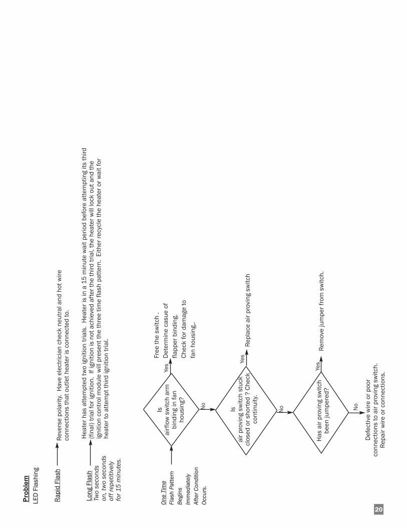
The ignition control module is self-diagnostic. The red lightlocated on the control will flash a specific pattern dependingupon the problem which is diagnosed. To use the flow charts, tidentify the problem by the light pattern of the L.E.D. (lightemitting code) diagnostic light. If the light is flashing, the flashpattern will be followed by a pause and then a repeat of theflash pattern until the problem is corrected. The light will onlybe on when the selector switch is positioned to HEAT and thethermostat or controller is calling for heat. The light will not beon when the selector switch is positioned to VENT.
Heating Mode Problems Page
L.E.D. light is not on during a call for heat. . . . . . . . . . . . . . . 19
L.E.D. diagnostic light is flashing:A. Rapid flash . . . . . . . . . . . . . . . . . . . . . . . . . . . . 20B. Long flash ( 2 seconds on-2 seconds off) . . . 20C. One time . . . . . . . . . . . . . . . . . . . . . . . . . . . . . . 20D. Two times . . . . . . . . . . . . . . . . . . . . . . . . . . . . . 21E. Three times. . . . . . . . . . . . . . . . . . . . . . . . . . . . 22F. Four times . . . . . . . . . . . . . . . . . . . . . . . . . . . . . 23G.Five times . . . . . . . . . . . . . . . . . . . . . . . . . . . . . 23H.Six times . . . . . . . . . . . . . . . . . . . . . . . . . . . . . . 23
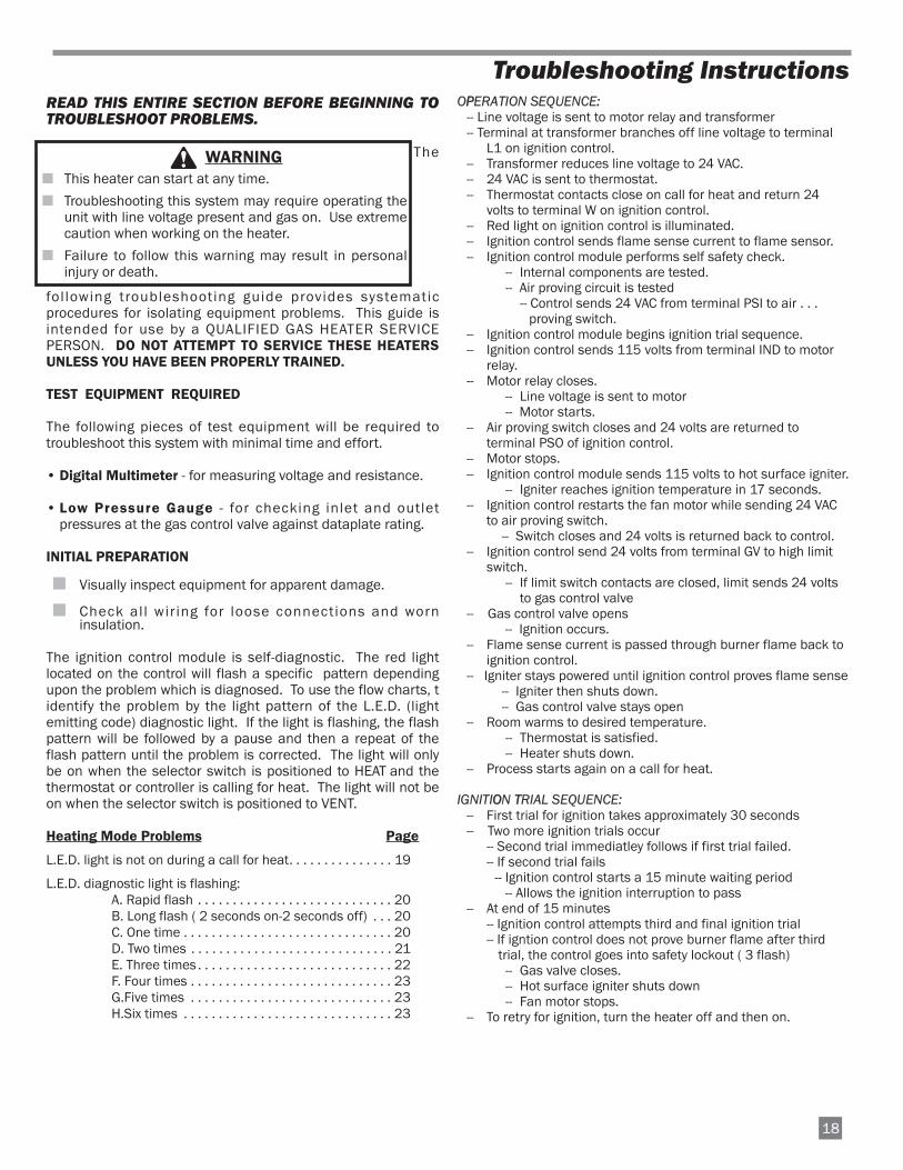
OPPERATION SEQUENCE:-- Line voltage is sent to motor relay and transformer-- Terminal at transformer branches off line voltage to terminal
L1 on ignition control.-- Transformer reduces line voltage to 24 VAC.-- 24 VAC is sent to thermostat.-- Thermostat contacts close on call for heat and return 24
volts to terminal W on ignition control.-- Red light on ignition control is illuminated.-- Ignition control sends flame sense current to flame sensor.-- Ignition control module performs self safety check.
-- Internal components are tested.-- Air proving circuit is tested
-- Control sends 24 VAC from terminal PSI to air . . . proving switch.
-- Ignition control module begins ignition trial sequence.-- Ignition control sends 115 volts from terminal IND to motor
relay.-- Motor relay closes.
-- Line voltage is sent to motor-- Motor starts.
-- Air proving switch closes and 24 volts are returned toterminal PSO of ignition control.
-- Motor stops.-- Ignition control module sends 115 volts to hot surface igniter.
-- Igniter reaches ignition temperature in 17 seconds.-- Ignition control restarts the fan motor while sending 24 VAC
to air proving switch.-- Switch closes and 24 volts is returned back to control.
-- Ignition control send 24 volts from terminal GV to high limitswitch.
-- If limit switch contacts are closed, limit sends 24 voltsto gas control valve
-- Gas control valve opens-- Ignition occurs.
-- Flame sense current is passed through burner flame back toignition control.
-- Igniter stays powered until ignition control proves flame sense -- Igniter then shuts down.-- Gas control valve stays open
-- Room warms to desired temperature.-- Thermostat is satisfied.-- Heater shuts down.
-- Process starts again on a call for heat.
IGNITIOON TTRIAL SEQUENCE:-- First trial for ignition takes approximately 30 seconds-- Two more ignition trials occur
-- Second trial immediatley follows if first trial failed.-- If second trial fails
-- Ignition control starts a 15 minute waiting period -- Allows the ignition interruption to pass
-- At end of 15 minutes-- Ignition control attempts third and final ignition trial-- If igntion control does not prove burner flame after third
trial, the control goes into safety lockout ( 3 flash)-- Gas valve closes.-- Hot surface igniter shuts down-- Fan motor stops.
-- To retry for ignition, turn the heater off and then on.
WARNING■ This heater can start at any time.
■ Troubleshooting this system may require operating theunit with line voltage present and gas on. Use extremecaution when working on the heater.
■ Failure to follow this warning may result in personalinjury or death.
18

19
Problem
LED
Con
stan
t On
LED
Ligh
tN
ot O
n
Nor
mal
Ope
ratio
n
Is p
rope
r vol
tage
supp
lied
to h
eate
r?
Chec
k da
ta p
late
for
elec
tric
al s
uppl
yre
quirm
ents
.Pr
ovid
e pr
oper
volta
ge, c
onta
ctel
ectr
icia
n.
Yes
No
Yes
Yes
Yes
Def
ectiv
e w
ire o
rel
ectr
ical
con
nect
ion.
Rea
pir o
r rep
lace
.
Is
ther
mos
tat
defe
ctiv
e? C
heck
for
cont
inui
ty.
Are
24 v
olts
supp
lied
to ig
nitio
nco
ntro
l ter
min
al W
from
ther
mos
tat?
Rep
lace
ther
mos
tat
Is h
eate
rco
nnec
ted
topo
wer
sup
ply?
No No
No
Yes
Ensu
re h
eate
r is
conn
ecte
d to
pow
ersu
pply
. Che
ckbr
eake
rs
Is tr
ansf
orm
erre
ceiv
ing
prop
ervo
ltage
?
Chec
k w
iring
for
cont
inui
ty b
etw
een
tran
sfor
mer
and
pow
ersu
pply
. Rep
air o
r rep
lace
No
Yes
Doe
str
ansf
orm
erre
duce
inco
min
gvo
ltage
to 2
4vo
lts?
Def
ectiv
e tr
ansf
orm
er.
Rel
ace
tran
sfor
mer
.
No
Is 2
4 v
olts
deliv
ered
toth
erm
osta
t?
Chec
k w
iring
bet
wee
ntr
ansf
orm
er a
ndth
erm
osta
t. Ch
eck
cont
inui
ty. R
epai
r as
need
ed.
No
Yes
Yes
Is
ther
mos
tat s
etab
ove
room
tem
pera
ture
?
Set t
herm
osta
tab
ove
room
tem
pera
ture
.
No
Def
ectiv
eig
nitio
n co
ntro
l.
20
Problem
LED
Fla
shin
g
One
Tim
eFl
ash
Patte
rnBe
gins
Imm
edia
tely
Afte
r Con
ditio
nOc
curs
.
Is
air p
rovi
ng s
witc
h st
uck
clos
ed o
r sho
rted
? C
heck
co
ntin
uity
.
Is
airf
low
sw
itch
arm
bind
ing
in fa
nho
usin
g?
Free
the
switc
h .
Det
erm
ine
casu
e of
flapp
er b
indi
ng.
Chec
k fo
r dam
age
tofa
n ho
usin
g,.
Yes
Yes
NoNo
Rep
lace
air
prov
ing
switc
h
Def
ectiv
e w
ire o
r poo
rco
nnec
tions
to a
ir pr
ovin
g sw
itch.
Rep
air w
ire o
r con
nect
ions
.
Has
air
prov
ing
switc
hbe
en ju
mpe
red?
Yes
No
Rem
ove
jum
per f
rom
sw
itch.
Rap
id F
lash
Rev
erse
pol
arity
. H
ave
elec
tric
ian
chec
k ne
utra
l and
hot
wire
conn
ectio
ns th
at o
utle
t hea
ter i
s co
nnec
ted
to.
Long
Fla
shTw
o se
cond
son
, tw
o se
cond
sof
f rep
etiti
vely
fo
r 15
min
utes
.
Hea
ter h
as a
ttem
pted
two
igni
tion
tria
ls.
Hea
ter i
s in
a 1
5 m
inut
e w
ait p
erio
d be
fore
att
empt
ing
its th
ird(f
inal
) tria
l for
igni
tion.
If i
gniti
on is
not
ach
ieve
d af
ter t
he th
ird tr
ial,
the
heat
er w
ill lo
ck o
ut a
nd th
eig
nitio
n co
ntro
l mod
ule
will
pre
sent
the
thre
e tim
e fla
sh p
atte
rn.
Eith
er re
cycl
e th
e he
ater
or w
ait f
orhe
ater
to a
ttem
pt th
ird ig
nitio
n tr
ial.
221
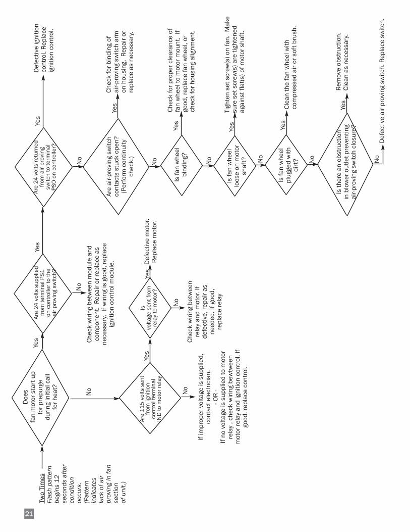
Two
Tim
esFl
ash
patte
rnbe
gins
12
seco
nds
afte
rco
nditi
onoc
curs
.(P
atte
rnin
dica
tes
lack
of a
irpr
ovin
g in
fan
sect
ion
of u
nit.)
Are
air-p
rovi
ng s
witc
hco
ntac
ts s
tuck
ope
n?(P
erfo
rm c
ontin
uity
chec
k.)
Doe
s fa
n m
otor
sta
rt u
pfo
r pre
purg
edu
ring
initi
al c
all
for h
eat?
Is fa
n w
heel
bind
ing?
Is fa
n w
heel
loos
e on
mot
orsh
aft?
Yes
Yes
Yes
No
Chec
k fo
r bin
ding
of
air-p
rovi
ng s
witc
h ar
mon
hou
sing
, R
epai
r or
repl
ace
as n
eces
sary
.
Yes
Yes
Chec
k fo
r pro
per c
lear
ance
of
fan
whe
el to
mot
or m
ount
. If
good
, rep
lace
fan
whe
el, o
rch
eck
for h
ousi
ng a
lignm
ent.
Tigh
ten
set s
crew
(s) o
n fa
n. M
ake
sure
set
scr
ew(s
) are
tigh
tene
dag
ains
t fla
t(s)
of m
otor
sha
ft.
Yes
Clea
n th
e fa
n w
heel
with
co
mpr
esse
d ai
r or s
oft b
rush
.
Yes
Rem
ove
obst
ruct
ion.
Cl
ean
as n
eces
sary
.
No
Is fa
n w
heel
plug
ged
with
dirt
?
Is th
ere
an o
bstr
uctio
n in
blo
wer
out
let p
reve
ntin
gai
r-pro
ving
sw
itch
clos
ure?
No
Are
115
vol
ts s
ent
from
igni
tion
cont
rol t
erm
inal
IND
to m
otor
rela
y
No
If im
prop
er v
olta
ge is
sup
plie
d,co
ntac
t ele
ctric
ian.
- OR
-If
no v
olta
ge is
sup
plie
d to
mot
orre
lay
, che
ck w
iring
bew
twee
nm
otor
rela
y an
d ig
nitio
n co
ntro
l. If
good
, rep
lace
con
trol
.
No
Yes
Are
24 v
olts
sup
plie
dfr
om te
rmin
al P
S1on
con
trol
ler t
o th
eai
r pro
ving
sw
itch?
Chec
k w
iring
bet
wee
n m
odul
e an
dco
mpo
nent
. R
epai
r or r
epla
ce a
sne
cess
ary.
If w
iring
is g
ood,
repl
ace
igni
tion
cont
rol m
odul
e.
No
Is
volta
ge s
ent f
rom
rela
y to
mot
or?
Chec
k w
iring
bet
wee
nre
lay
and
mot
or. I
fde
fect
ive,
repa
ir as
need
ed. I
f goo
d,re
plac
e re
lay
No
Yes
Def
ectiv
e m
otor
.R
epla
ce m
otor
.
Yes
Are
24 v
olts
retu
rned
from
air
prov
ing
switc
h to
term
inal
PSO
on
cont
rolle
r?
No
Def
ectiv
e ig
nitio
nco
ntro
l. R
epla
ceig
nitio
n co
ntro
l.
No
No
Def
ectiv
e ai
r pro
ving
sw
itch.
Rep
lace
sw
itch.

222Thre
e Ti
mes
Igni
tion
failu
re H
eate
rdo
es n
ot li
ght
or s
tay
lit.
Is
LP ta
nkfu
ll an
d pr
oper
ly
size
d an
d ar
e al
l gas
su
pply
val
ves
to
heat
er o
pen?
Fill
tank
or r
esiz
e if
nece
ssar
y. O
pen
all
gas
supp
ly v
alve
s
Yes
No
Is p
rope
r gas
pres
sure
sup
plie
dto
hea
ter?
Yes
Are
24 v
olts
sen
tfr
om te
rmin
al G
Vof
con
trol
ler t
ohi
gh li
mit
switc
haf
ter i
gnite
r war
mup
and
fan
mot
orre
star
ts?
Hav
e th
e bu
rner
or
ifice
, bur
ner
cast
ing
and
man
ifold
been
che
cked
for
bloc
kage
?
Yes
Yes
Is p
rope
r bu
rner
man
ifold
pres
sure
read
at
outle
t of g
as
valv
e?
Doe
s ig
nite
rgl
ow?
Is fl
ame
sens
or c
lean
?
Is ig
nite
rpr
oper
lyco
nnec
ted?
Are
115
vol
tssu
pplie
d fr
omte
rmin
al H
SI o
nig
nitio
n co
ntro
lm
odul
e to
ig
nite
r?
Yes
Yes
Are
high
lim
itsw
itch
cont
acts
clos
ed?
Yes
Yes
Yes
(A)
If lo
w o
r hig
h pr
essu
reis
read
, adj
ust o
utle
tpr
essu
re.
(B)
If ga
s pr
essu
re is
not
read
, rep
lace
the
gas
cont
rol v
alve
.D
efec
tive
igni
ter.
Perf
orm
con
tinui
tych
eck
and
repl
ace
igni
ter I
f nec
essa
ry.
Clea
n fla
me
sens
orw
ith e
mer
y cl
oth
orst
eel w
ool.
Conn
ect i
gnite
rto
igni
ter p
ower
supp
ly w
iring
.
Chec
k w
iring
bet
wee
n m
odul
e an
dco
mpo
nent
. R
epai
r or r
epla
ce a
sne
cess
ary
or re
plac
e ig
nitio
n co
ntro
l .
Prov
ide
prop
erpr
essu
re to
hea
ter
and
chec
k w
ith a
gaug
e.
Chec
k fo
r vol
tage
tosw
itch.
Che
ck w
iring
and
repa
ir if
defe
ctiv
eIf
wiri
ng is
goo
d an
dvo
ltage
is n
ot p
rese
nt,
repl
ace
igni
tion
cont
rol.
No
Rem
ove
orifi
ce a
ndbu
rner
cas
ting.
Blo
wou
t with
com
pres
sed
air o
r cle
an w
ith a
soft
bru
sh.
No
No
No
No
No
No
No
No
Has
wiri
ng b
een
chec
ked
betw
een
igni
tion
cont
rol a
ndse
nsor
?
Yes
Chec
k w
iring
bet
wee
nm
odul
e an
dco
mpo
nent
. R
epai
ror
repl
ace
.
No
Is
flam
e se
nsor
insu
lato
rcr
acke
d?
Yes
Rep
lace
sens
or.
No
Is
flam
e se
nsor
prop
erly
posi
tione
d?
Yes
Posi
tion
flam
ese
nsor
so
1/2
- 3
/4 in
. of t
ip is
inbu
rner
flam
e.
No
Is h
eate
rpr
oper
lygr
ound
ed?
Cont
act e
lect
ricia
n.Sy
stem
mus
t be
grou
nded
for
prop
er o
pera
tion.
No
Are
24 v
olts
supp
lied
from
the
high
lim
itsw
itch
to th
e ga
sco
ntro
l val
ve?
Yes
Chec
k fo
r vol
tage
tova
lve.
Che
ck w
iring
and
repa
ir if
defe
ctiv
e.If
wiri
ng is
goo
d an
dvo
ltage
is n
ot p
rese
nt,
repl
ace
limit
switc
h.
No
Perf
orm
con
tinui
ty c
heck
. If
switc
h is
ope
n re
set t
he s
witc
h.
Chec
k th
e fo
llow
ing:
--
Conf
irm c
orre
ct fu
el fo
r hea
ter.
-- Pr
oper
vol
tage
to m
otor
--
Dus
t and
dir
t bu
ild-u
p --
Plug
ged
fan
asse
mbl
y --
Fan
not t
ight
ened
to m
otor
--
Obs
truc
tions
in a
ir in
lets
or
disc
harg
e ou
tlet o
f hea
ter.
Yes

223
Five
Tim
esRa
pid
On/O
ffcy
clin
g of
the
burn
er.
See
flam
e se
nsor
rela
ted
prob
lem
s in
thre
e tim
e fla
sh p
atte
rn.
Six
Tim
es
Low
mic
roam
p ou
tput
from
flam
e se
nsor
. The
hea
ter w
illco
ntin
ue to
ope
rate
as
norm
al.
Flam
e se
nse
is lo
w a
nd th
atfla
me
failu
re o
r im
prop
er o
pera
tion
can
occu
r at a
ny ti
me.
See
flam
e se
nsor
rela
ted
prob
lem
s in
thre
e tim
e fla
sh p
atte
rn.
Four
Tim
esIf
HSI
boa
rd d
oes
not r
eset
, the
n re
plac
e th
e bo
ard.
(In
tern
al b
oard
faul
t.)If
HSI
boa
rd re
sets
, the
n ha
ve q
ualif
ied
elec
tric
ian
chec
k po
wer
sou
rce
for
pow
er q
ualit
y pr
oble
ms.
(Fre
quen
cy, l
ine
nois
e, li
ne s
pike
s, lo
ose
conn
ectio
ns,
too
smal
l wire
gau
ge.)

224
Electrical Connection and Ladder Diagram
115 Volt Supply
120 V
OLT

225
230 Volt Supply
120 V
OLT

226
Heater Component Function
Air Proving Switch
Safety device used to insure that the proper air flow is beingachieved before the gas valve is opened.
Burner
Cast iron component used to channel gas and provide anarea at which the fuel may ignite.
Burner Orifice
Brass metering device used to feed gas to burner at aspecific rate.
Fan Housing
Chamber used for delivering air for efficient air movement.
Fan Wheel
Component used in conjunction with the motor and fanhousing to pull the hot air from heater and blow it into roomfor heating (also known as a squirrel cage).
Gas Control Valve
A device which consists of a low pressure regulator andelectrical solenoids which are used for the control of gasflow to the burner assembly. A feature of the control is abuilt in gas shut off which is used to isolate the heater fromits gas supply when servicing.
Gas Hose
Flexible connector used to convey gas from supply line inbuilding to heater.
Heat Chamber
Metal “fire box” within the appliance that provides an areawhere burner flame mixes with combustion air, therebyproviding heat.
High Limit Switch
Safety device wired into the control system which is used tobreak an electrical circuit to the gas control valve in event ofoverheat situation.
Hot Surface Igniter
Ignition device used on automatic ignition control systems.Ignites gas by surface temperature rather than spark orflame.
Ignition Control Module
Electronic printed circuit board which sends and receivesvoltages to various controls in an automatic ignition system.An important safety feature of the control board is that it willshut down the entire heater, thereby stopping the flow offuel gas if burner flame goes out.
Motor
Electric device used to force preheated air through theheater and to circulate heat within a certain area. Convertselectrical energy into mechanical energy.
Motor Relay
Electrical component wired between ignition control andmotor. Used to feed voltage to motor upon receipt of voltagefrom ignition control.
Regulator
Mechanical device used in L.P. and natural gas distributionsystems to reduce a higher inlet pressure to a preset lowerpressure. The regulator is responsible to supply a steadyoutlet pressure to the heater(s) despite changes in inletpressure, heater demand and weather conditions.
Thermostat (Accessory)
Electrical device used as an automatic “on/off” switchwhich will respond to changes in temperature in a certainarea. Can be wired so contacts in the thermostat open orclose on temperature increase or decrease.
Transformer
Electrical control used to accept line power supply primaryvoltage and reduce it to lower secondary voltage to operatecertain control systems.

227
28
30
37
38
3921
20
19
16
17
6
5
7
89
10
11
12
4
3
2
1
14
31
32
33
34
35
26
27
29
36
22 25
13
18
15
24
23
Parts Identification
PARTS SCHEMATIC
228
Parts Identification
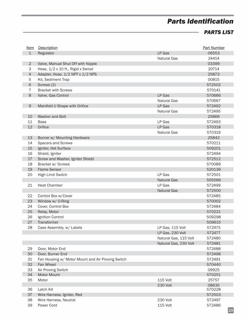
PARTS LIST
Item Description Part Number1 Regulator LP Gas 06553
Natural Gas 244142 Valve, Manual Shut Off with Nipple 033993 Hose, 1/2 x 10 ft., Rigid x Swivel 207144 Adapter, Hose, 1/2 NPT x 1/2 NPS 258735 Kit, Sediment Trap 008156 Screws (2) 5725027 Bracket with Screws 5701418 Valve, Gas Control LP Gas 570666
Natural Gas 5706679 Manifold U Shape with Orifice LP Gas 572492
Natural Gas 57249510 Washer and Bolt 2586611 Base LP Gas 57249312 Orifice LP Gas 570318
Natural Gas 57031913 Burner w/ Mounting Hardware 2584214 Spacers and Screws 57021115 Igniter, Hot Surface 50920116 Shield, Igniter 57249417 Screw and Washer, Igniter Shield 57251218 Bracket w/ Screws 57008919 Flame Sensor 52013920 High Limit Switch LP Gas 572501
Natural Gas 50556621 Heat Chamber LP Gas 572499
Natural Gas 57250022 Control Box w/Cover 57248523 Window w/ O-Ring 57000224 Cover, Control Box 57248425 Relay, Motor 57022126 Ignition Control 50929827 Transformer 50961528 Case Assembly, w/ Labels LP Gas, 115 Volt 572475
LP Gas, 230 Volt 572477Natural Gas, 115 Volt 572480Natural Gas, 230 Volt 572481
29 Door, Motor End 57248830 Door, Burner End 57249831 Fan Housing w/ Motor Mount and Air Proving Switch 57249132 Fan Wheel 57044033 Air Proving Switch 0992534 Motor Mount 57025135 Motor 115 Volt 25757
230 Volt 0863536 Latch Kit 57022837 Wire Harness, Igniter, Red 57250338 Wire Harness, Neutral 230 Volt 57249739 Power Cord 115 Volt 572486
Contact your local L.B. White dealer for replacement partsand service or call the L.B. White Co., Inc. at (800) 345-7200for assistance. Be sure that you have your heater modelnumber and configuration number when calling.
L.B. White Co., Inc. warrants that the component parts of itsheater are free from defects in material and workmanship,when properly installed, operated, and maintained inaccordance with the Instal lation and MaintenanceInstructions, safety guides and labels contained with eachunit. If, within 12 months from the date of purchase bythe end user, any component is found to be defective,L.B. White Co., Inc. will at its option, repair or replace thedefective part or heater, with a new part or heater, F.O.B.,Onalaska, Wisconsin.
A warranty card on file at L.B. White will automaticallyqualify a unit and its component par ts for warrantyconsideration. If a warranty card is not on file, a copy of thebil l of sale wil l be required to establish warrantyqualification. If neither is available, the warranty period willbe 12 months from date of shipment from L.B. White.
Warranty Policy
Replacement Parts and Service
HEATER
PARTS
L.B. White Co., Inc. warrants that replacement partspurchased from the company and used on the appropriateL. B. White equipment are free from defects both in materialand workmanship for 12 months from the date ofpurchase by the end user. Warranty is automatic if acomponent is found defective within 12 months of the datecode marked on the part. If the defect occurs more than 12months later than the date code but within 12 months fromthe date of purchase by the end user, a copy of a bill of salewill be required to establish warranty qualification.
The warranty set forth above is the exclusive warrantyprovided by L.B. White, and all other warranties, includingany implied warranties or merchantability or fitness for aparticular purpose, are expressly disclaimed. In the eventany implied warranty is not hereby effectively disclaimeddue to operation of law, such implied warranty is limited in
duration to the duration of the applicable warranty statedabove. The remedies set forth above are the sole andexclusive remedies available hereunder. L.B. White will notbe liable for any incidental or consequential damagesdirectly or indirectly related to the sale, handling or use ofthe equipment, and in any event L.B. White's liability inconnection with the equipment, including for claims basedon negligence or strict liability, is limited to the purchaseprice.
Some states do not allow limitations on how long an impliedwarranty lasts, so the above limitation may not apply to you.Some states do not allow the exclusion or limitation ofincidental or consequential damages, so the abovelimitation or exclusion may not apply to you. This warrantygives you specific legal rights, and you may also have otherrights which vary from state to state.
29