owner’s manual air compressor 3-gallon 1 hp oil ... s manual air compressor 3-gallon 1 hp oil...
TRANSCRIPT
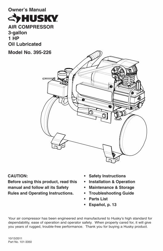
Owner’s Manual
AIR COMPRESSOR3-gallon1 HPOil Lubricated
Model No. 395-226
Your air compressor has been engineered and manufactured to Huskyʼs high standard for dependability, ease of operation and operator safety. When properly cared for, it will give you years of rugged, trouble-free performance. Thank you for buying a Husky product.
10/13/2011Part No. 101-3350
CAUTION: Before using this product, read this manual and follow all its Safety Rules and Operating Instructions.
• Safety Instructions• Installation & Operation• Maintenance & Storage• Troubleshooting Guide• Parts List• Español, p. 13

TABLE OF CONTENTSPage
Safety Instructions . . . . . . . . . . . . . . . . . . . . . . . . . . . . . . . . . . . . . . . . . . . . . . . . . . . . . . . . . . . . . . . . .1
Important Safety Instructions & Guidelines . . . . . . . . . . . . . . . . . . . . . . . . . . . . . . . . . . . . . . . . . . . . . .1
Specifications . . . . . . . . . . . . . . . . . . . . . . . . . . . . . . . . . . . . . . . . . . . . . . . . . . . . . . . . . . . . . . . . . . . .2
Glossary . . . . . . . . . . . . . . . . . . . . . . . . . . . . . . . . . . . . . . . . . . . . . . . . . . . . . . . . . . . . . . . . . . . . . . . .2
Duty Cycle . . . . . . . . . . . . . . . . . . . . . . . . . . . . . . . . . . . . . . . . . . . . . . . . . . . . . . . . . . . . . . . . . . . . . . .2
Parts & Features . . . . . . . . . . . . . . . . . . . . . . . . . . . . . . . . . . . . . . . . . . . . . . . . . . . . . . . . . . . . . . . . .3
Installation & Assembly . . . . . . . . . . . . . . . . . . . . . . . . . . . . . . . . . . . . . . . . . . . . . . . . . . . . . . . . . . . . .4
Operating Procedures . . . . . . . . . . . . . . . . . . . . . . . . . . . . . . . . . . . . . . . . . . . . . . . . . . . . . . . . . . . . .6
Maintenance . . . . . . . . . . . . . . . . . . . . . . . . . . . . . . . . . . . . . . . . . . . . . . . . . . . . . . . . . . . . . . . . . . . . .7
Storage . . . . . . . . . . . . . . . . . . . . . . . . . . . . . . . . . . . . . . . . . . . . . . . . . . . . . . . . . . . . . . . . . . . . . . . . .7
Troubleshooting Guide . . . . . . . . . . . . . . . . . . . . . . . . . . . . . . . . . . . . . . . . . . . . . . . . . . . . . . . . . . . . .8
Exploded View . . . . . . . . . . . . . . . . . . . . . . . . . . . . . . . . . . . . . . . . . . . . . . . . . . . . . . . . . . . . . . . . . . . .9
Parts List . . . . . . . . . . . . . . . . . . . . . . . . . . . . . . . . . . . . . . . . . . . . . . . . . . . . . . . . . . . . . . . . . . . . . . .10
Warranty . . . . . . . . . . . . . . . . . . . . . . . . . . . . . . . . . . . . . . . . . . . . . . . . . . . . . . . . . . . . . . . . . . . . . . .12

1
Safety InstructionsThe information listed below should be read and understood by the operator. This information is given to protect the user while operating and stor-
ing the air compressor. We utilize the symbols below to allow the reader to recognize important information about their safety.
Indicates an imminently hazardous situation which, if not avoided, will result in death or seri-
ous injury.
CAUTIONIndicates a potentially hazardous situation
which, if not avoided, may result in minor or moderate injury.
WARNINGIndicates a potentially hazardous situation
which, if not avoided, could result in death or serious injury.
CAUTIONWhen used without the safety alert symbol indi-cates a potentially hazardous situation which, if
not avoided, may result in property damage.
Important Safety Instructions and Guidelines • Save all instructions
WARNINGImproper operation or maintenance of this product could result in serious injury and/or property damage. Read and understand all of the warnings and safety instructions provided before using this equipment.
CALIFORNIA PROPOSITION 65 WARNING: This product contains chemicals known to the State of California to cause cancer, birth defects and/or reproductive harm.
CAUTION
The air compressor should be operated on a dedicated 15 amp circuit. If the circuit does not have 15 free amps available, a larger circuit must be used. Always use more air hose before utilizing extension cords. All exten-sion cords used must be 12 gauge with a maximum length of 25 ft. The circuit fuse type must be a time delay. Low voltage could cause damage to the motor.
Risk of Moving Parts If the air compressor is in operation, all guards and covers should be attached or installed correctly. If any guard or cover has been damaged, do not operate the equipment until the proper personnel has correctly re-paired the equipment. The power cord should be free of any moving parts, twisting and/or crimping while in use and while in storage.
Risk of Burns There are surfaces on your air compressor that while in operation and thereafter can cause serious burns if touched. The equipment should be allowed time to cool before any maintenance is attempted. Items such as the compressor pump and the outlet tube are normally hot during and after operation.
Risk of Falling Operation of the air compressor should always be in a position that is stable. Never use the air compressor on a rooftop or elevated position that could allow the unit to fall or be tipped over. Use additional air hose for elevated jobs.
Risk from Flying Objects Always wear ANSI Z87.1 approved safety glasses with side shields when the air compressor is in use. Turn off the air compressor and drain the air tank before performing any type of maintenance or disassembly of the hoses or fi ttings. Never point any nozzle or sprayer toward any part of the body or at other people or animals.
DANGER

2
Important Safety Instructions & Guidelines
Risk to Breathing Avoid using the air compressor in confi ned areas. Always have adequate space (12 inches) on all sides of the air compressor. Also keep children, pets, and others out of the area of operation. This air compressor does not provide breathable air for anyone or any auxiliary breathing device. Spraying material will always need to be in another area away from the air compressor to not allow intake air to damage the air compressor fi lter.
Risk of Electrical Shock Never utilize the air compressor in the rain or wet conditions. Any electrical issues or repairs should be performed by authorized personnel such as an electrician and should comply with all national and local electrical codes. The air compressor should also have the proper three prong grounding plug, correct voltage, and adequate fuse protection.
Risk of Explosion or Fire
Never operate the compressor near combustible materials, gasoline or solvent vapors. If spraying fl ammable materials, locate the air compressor at least 20 feet away from the spray area. Never operate the air compres-sor indoors or in a confi ned area.
Risk of Bursting Always drain the air compressor tank daily or after each use. If the tank develops a leak, then replace the air compressor. Never use the air com-pressor after a leak has been found or try to make any modifi cations to the tank. Never modify the air compressorʼs factory settings which control the tank pressure or any other function.
SpecificationsPump . . . . . . . . . . . . . . . . . .Oil-lube, direct driveMotor Induction. . . . . . . . . . . . . . . . . . . . . . .1 HPBore . . . . . . . . . . . . . . . . . . . . . . . . . . . . . . .1.65”Stroke . . . . . . . . . . . . . . . . . . . . . . . . . . . . . .1.26”Voltage Single Phase . . . . . . . . . . . . . . .120 VAC
Minimum Circuit Requirement . . . . . . . .15 AmpsAir Tank Capacity . . . . . . . . . . . . . . . . . 3 GallonsCut-in Pressure . . . . . . . . . . . . . . . . . . . . 95 PSICut-out Pressure . . . . . . . . . . . . . . . . . . 125 PSISCFM @ 90 PSI. . . . . . . . . . . . . . . . . . . . . . . 2.4
GlossaryCFM: Cubic feet per minute.SCFM: Standard cubic feet per minute; a unit of measure for air delivery.PSIG: Pounds per square inch gauge; a unit of measure for pressure.ASME: American Society of Mechanical Engineers.California Code: Unit may comply with California Code 462 (l) (2)/ (M) (2).Cut-In Pressure: The air compressor will automatically start to refill the tank when the pressure drops below the prescribed minimum.
Cut-Out Pressure: The point at which the motor stops when the tank has reached maximum air pressure.Code Certification: Products that bear one or more of the following marks: UL, CUL, ETL, CSA, have been evaluated by OSHA-certified independent safety laboratories and meet the applicable Underwriters Laboratories Standards for Safety.
Duty CycleThis is a 50% duty cycle air compressor. Do not run the air compressor more than 30 minutes of one hour. Doing so could damage the air compressor.

3
PressureRelief Tube
Outlet Tube
Oil Fill Cap
Oil Sight Gauge
Parts & FeaturesSee figures below for reference
Air Intake Filter Provides clean air to the pump and must always be kept free of debris. Check on a daily basis or before each use.
Regulator Gauge Indicates the outgoing air pressure to the tool and is controlled by the regulator.
Tank Pressure Gauge Indicates the reserve air pressure in the tank.
Pressure Switch This controls the power to the motor and also the cut-in/cut-out pressure settings. This switch serves as the Auto-On/Off posi-tions for the unit.
Tank Drain ValveUsed to drain condensation from the air tank. Located at bottom of tank.
Quick ConnectOffers a quick release feature for attaching and removing the air hose.
RegulatorThe air pressure coming from the air tank is controlled by the regulator. To increase the pres-sure, turn the knob clockwise, and to decrease the pressure, turn the knob counterclockwise.
Tank Safety ValveUsed to allow excess tank pressure to escape into the atmosphere. This valve should only open when the tank pressure is above the maximum rated pressure.
Check Valve When the pump is not in operation, the valve closes to retain air pressure inside the tank. An internal component.

4
To Install the Air Intake FilterRemove the plastic plug from the compressor head. Remove the air intake fi lter from the poly bag and thread it onto the head of the compressor as shown.
CAUTIONDo not attempt to start the air compressor without fi rst adding oil to the crankcase. Serious damage can result unless fi lled with oil. The pump is shipped without oil from the factory. Only use non-detergent oils since multi-viscos-ity motor oils leave carbon deposits on pump components, thus reducing performance and compressor life.
WARNINGDrain the tank to release all tank air pressure before removing the oil fi ll cap. Be sure the air vent in the oil fi ll cap (see fi gure to the right) is free from debris. If air vent is blocked, pressure can build in crankcase causing damage to the compressor and possible personal injury.
Lubrication and OilRemove the oil fi ll cap by turning it counter-clockwise by hand. Fill the compressor pump with an air compressor oil such as SAE-30 non-detergent (API CG/CD Heavy Duty) oil at slow intervals until the oil reaches the center of the red circle in the sight glass (see fi gure above). Use SAE-10 during extreme winter conditions.
Location of the Air CompressorThe air compressor should always be located in a clean, dry, and well ventilated environment. The unit should have at minimum, 12 inches of space on each side. The air fi lter intake should be free of any debris or obstructions. Check the air fi lter on a daily basis to be sure it is clean and in working order.
Installation & Assembly
WARNINGThe air compressor should be turned off and unplugged from the power source before any mainte-nance is performed as well as the air bled from the tank and the unit allowed time to cool. Personal injuries could occur from moving parts, electrical sources, compressed air or hot surfaces. The regu-lator assembly must be attached before use. Failure to assemble correctly could result in leaks and possible injury. If unsure of assembly instructions or you experience diffi culty in the assembly please call your local service department for further instruction.
Grounding InstructionsThis product should be grounded. In the event of an electrical short circuit, grounding reduces the risk of electric shock by providing an escape wire for the electric current. This product is equipped with a cord having a grounding wire with an ap-propriate grounding plug. (See the fi gure below.) The plug must be plugged into an outlet that is properly installed and grounded in accordance with all local codes and ordinances. Check with a qualifi ed electrician or service personnel if these instructions are not completely understood or if in doubt as to whether the tool is properly grounded.
Grounded Outlet
Grounding Pin
Plug

5
WARNINGImproper installation of the grounding plug will result in a risk of electric shock. If repair or replace-ment of the cord or plug is necessary, do not connect the grounding wire to either fl at blade terminal. The wire with insulation having an outer surface that is green with or without yellow stripes is the grounding wire. Check with a qualifi ed electrician or serviceman if the grounding instructions are not completely understood, or if in doubt as to whether the product is properly grounded. Do not modify the plug provided; if it will not fi t the outlet, have the proper outlet installed by a qualifi ed electrician.
This product is for use on a circuit having a nominal rating of 120 volts and is factory-equipped with a specifi c electric cord and plug to permit connection to a proper electric circuit. Make sure that the product is connected to an outlet having the same confi guration as the plug. No adapter should be used with this product. If the product must be reconnected for use on a different type of electric circuit, qualifi ed service personnel should make the reconnection.
Extension CordsUse only a 3-wire extension cord that has a 3-blade grounding plug, and a 3-slot receptacle that will accept the plug on the product. Make sure your extension cord is in good condition. When using an extension cord, be sure to use one heavy enough to carry the current your product will draw. Cords must not exceed 25 feet and No. 12 AWG size must be used. An undersized cord will cause a drop in line voltage resulting in loss of power and overheating.
Break In ProceduresNo break in procedure is required by the user. This product is factory tested to ensure proper opera-tion and performance.
Installation & Assembly
NOTES

6
Daily Start-Up Procedures➀ Set the Auto-On/Off lever to the Off position.
➁ Check the air compressor visually for any damage or obstruction.
➂ Close the drain valve.
➃ Check the oil level of the pump.
➄ Connect the air hose to the quick connect socket on the regulator assembly by inserting the quick connect plug on the air hose into the quick connect socket. The quick connect socket collar will snap forward and lock the plug into place providing an air tight seal between the socket and plug. To release the air hose, push the collar back on the quick connect socket.
➅ Plug the power cord into the proper receptacle.➆ Turn the Auto-On/Off lever to the On-Auto
Operating Procedures position, and the compressor will start and build air pressure in the tank to cut-out pressure and then shut off automatically.
➇ Adjust the regulator to a PSI setting that is needed for your application, and be sure it is within the safety standards required to perform the task. If using a pneumatic tool, the manufacturer should have recommendations in the manual for that particular tool on operating PSI settings.
Note: The air compressor is now ready for use. The following infl ation and cleaning accessories packaged with this unit should only be oper-ated at maximum pressure of 20-30 PSI: blow gun, tapered nozzle, infl ation needles, blow gun adapter.
!
147
5
6
3
8
Daily Shut-Down Procedures1. Set the Auto-On/Off lever to the Off position.2. Unplug the power cord from the receptacle.3. Set the outlet pressure to zero on the regulator.4. Remove any air tools or accessories. When draining the tank, always use ear and eye protection. Drain the tank in a suitable location; condensation will be present in most cases of draining.5. Open the drain valve allowing air to bleed from the tank. After all of the air has bled from the tank, close the drain valve to prevent debris buildup in the valve.
CAUTIONWhen draining the tank, always use ear and eye protection. Drain the tank in a suitable location; condensation will be present in most cases of draining.
WARNINGWater that remains in the tank during storage will corrode and weaken the air tank which could cause the tank to rupture. To avoid serious injury, be sure to drain the tank after each use or daily.

7
NOTE: Any service procedure not covered in the maintenance schedule below should be performed by qualifi ed service personnel.
Maintenance
Items to Check/Change Before each use or daily
After fi rst 10 hours
Every 100 hours
Check Tank Safety Valve X
Overall Unit Visual Check X
Check Oil Level X
Change Oil X X
Check Air Filter (more frequently in dusty or humid environments)
X
Drain Tank (after each use or daily) X
CAUTIONTo ensure effi cient operation and longer life of the air compressor unit, a routine maintenance schedule should be followed. The following schedule is geared toward a consumer whose compressor is used in a normal working environ-ment on a daily basis. If necessary, the schedule should be modifi ed to suit the conditions under which your compressor is used. The modifi ca-tions will depend upon the hours of operation and the working environment. Air compressors used in an extremely dirty and/or hostile envi-ronment will require a greater frequency of all maintenance checks.
WARNINGThe air compressor should be turned off and unplugged from the power source before any maintenance is performed as well as the air bled from the tank and the unit allowed time to cool. Personal injuries could occur from moving parts, electrical sources, compressed air or hot surfaces.
1. Turn the unit off and unplug the power cord from the receptacle.2. Allow the compressor time to cool if it has been in operation.3. Open the drain valve to bleed all air from the tank.4. Close the drain valve. 5. Remove the oil fi ll cap on the pump.6. Remove the sight glass with a box end wrench or socket. Drain the oil into a suitable container and dispose of properly. The compressor may need to be tipped slightly towards the drain hole to allow all of the oil to drain.
7. Reattach the sight glass. Note: Torque the sight glass 10-12 inch lbs. when re-assembling. Be sure the gasket is between the sight glass and the pump crankcase. 8. Refi ll the compressor pump with an air compressor oil such as SAE-30 non-detergent (API CG/CD Heavy Duty) oil at slow intervals until the oil reaches the center of the red circle in the sight glass. Use a SAE-10 during extreme winter conditions.
Oil ChangingFor changing the pump oil, be sure to do the following:
StorageFor storing the air compressor, be sure to do the following:
1. Turn the unit off and unplug the power cord from the receptacle.2. Remove all air hoses, accessories, and air tools from the air compressor.3. Perform the daily maintenance schedule.
4. Open the drain valve to bleed all air from the tank.5. Close the drain valve. 6. Store the air compressor in a clean and dry location.
8
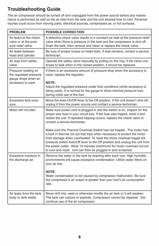
The air compressor should be turned off and unplugged from the power source before any mainte-nance is performed as well as the air bled from the tank and the unit allowed time to cool. Personal injuries could occur from moving parts, electrical sources, compressed air, or hot surfaces.
Troubleshooting Guide
PROBLEM POSSIBLE CORRECTION
Air leaks at the check valve or at the pres-sure relief valve.
A defective check valve results in a constant air leak at the pressure relief valve when there is pressure in the tank and the compressor is shut off. Drain the tank, then remove and clean or replace the check valve.
Air leaks between head and cylinder.
Be sure of proper torque on head bolts. If leak remains, contact a service technician.
Air leak from safety valve.
Operate the safety valve manually by pulling on the ring. If the valve con-tinues to leak when in the closed position, it should be replaced.
Pressure reading on the regulated pressure gauge drops when an accessory is used.
If there is an excessive amount of pressure drop when the accessory is used, replace the regulator.
NOTE: Adjust the regulated pressure under fl ow conditions (while accessory is being used). It is normal for the gauge to show minimal pressure loss during initial use of the tool.
Excessive tank pres-sure.
Move the Auto-On/Off lever to the Off position. If the unit doesnʼt shut off, unplug it from the power source and contact a service technician.
Motor will not start. Make sure power cord is plugged in and the switch is on. Inspect for the proper size fuse in your circuit box. If the fuse was tripped, reset it and restart the unit. If repeated tripping occurs, replace the check valve or contact a service technician.
Make sure the Thermal Overload Switch has not tripped. The motor has a built in thermal cut out that trips when necessary to protect the motor from damage when overheated. To reset the motor overload toggle the pressure switch Auto/Off lever to the Off position and unplug the unit from the power outlet. Allow 10 minutes (minimum) for motor overload cut-out to cool and reset. Unit can then be plugged in and re-started.
Excessive moisture in the discharge air.
Remove the water in the tank by draining after each use. High humidity environments will cause excessive condensation. Utilize water fi lters on your air line.
NOTE:Water condensation is not caused by compressor malfunction. Be sure the compressorʼs air output is greater than your toolʼs air consumption rate.
Air leaks from the tank body or tank welds.
Never drill into, weld or otherwise modify the air tank or it will weaken. The tank can rupture or explode. Compressor cannot be repaired. Dis-continue use of the air compressor.

9
Husky Air Compressor Model 395-226 Exploded View
1
2
3
4
5
6
7
8
9
102
11
1213
141516
17
18
19
20
21
22
23
24
2526
27
33
3635
34
37
4243
4445
48
4746
28
40
41 4950
51
52
53
54 49
40
41
55
56
5758
59
60
61 62
63
394041
2838
10
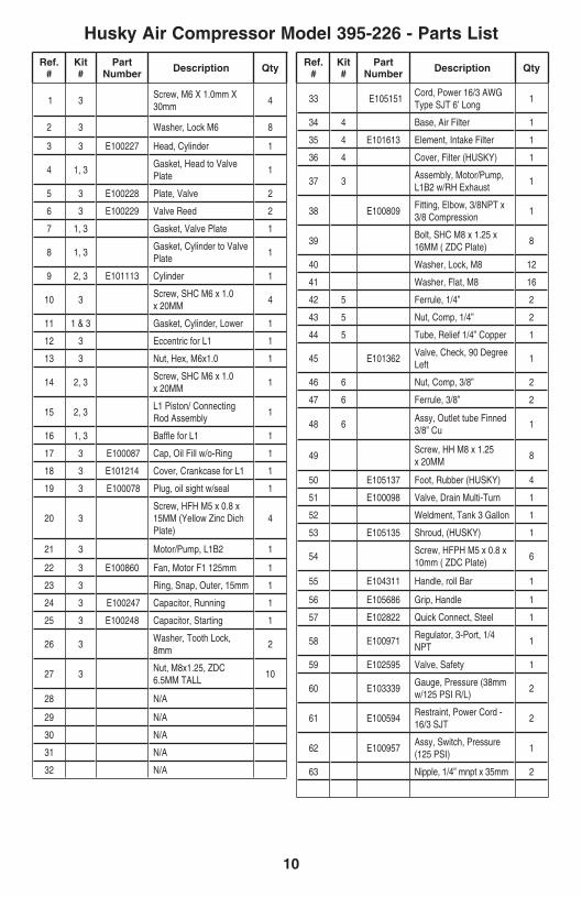
Husky Air Compressor Model 395-226 - Parts List
Ref. #
Kit #
Part Number Description Qty
1 3Screw, M6 X 1.0mm X 30mm
4
2 3 Washer, Lock M6 8
3 3 E100227 Head, Cylinder 1
4 1, 3Gasket, Head to Valve Plate
1
5 3 E100228 Plate, Valve 2
6 3 E100229 Valve Reed 2
7 1, 3 Gasket, Valve Plate 1
8 1, 3Gasket, Cylinder to Valve Plate
1
9 2, 3 E101113 Cylinder 1
10 3 Screw, SHC M6 x 1.0 x 20MM
4
11 1 & 3 Gasket, Cylinder, Lower 1
12 3 Eccentric for L1 1
13 3 Nut, Hex, M6x1.0 1
14 2, 3 Screw, SHC M6 x 1.0 x 20MM
1
15 2, 3 L1 Piston/ Connecting Rod Assembly
1
16 1, 3 Baffle for L1 1
17 3 E100087 Cap, Oil Fill w/o-Ring 1
18 3 E101214 Cover, Crankcase for L1 1
19 3 E100078 Plug, oil sight w/seal 1
20 3 Screw, HFH M5 x 0.8 x 15MM (Yellow Zinc Dich Plate)
4
21 3 Motor/Pump, L1B2 1
22 3 E100860 Fan, Motor F1 125mm 1
23 3 Ring, Snap, Outer, 15mm 1
24 3 E100247 Capacitor, Running 1
25 3 E100248 Capacitor, Starting 1
26 3 Washer, Tooth Lock, 8mm
2
27 3 Nut, M8x1.25, ZDC 6.5MM TALL
10
28 N/A
29 N/A
30 N/A
31 N/A
32 N/A
Ref. #
Kit #
Part Number Description Qty
33 E105151Cord, Power 16/3 AWG Type SJT 6’ Long
1
34 4 Base, Air Filter 1
35 4 E101613 Element, Intake Filter 1
36 4 Cover, Filter (HUSKY) 1
37 3Assembly, Motor/Pump, L1B2 w/RH Exhaust
1
38 E100809Fitting, Elbow, 3/8NPT x 3/8 Compression
1
39Bolt, SHC M8 x 1.25 x 16MM ( ZDC Plate)
8
40 Washer, Lock, M8 12
41 Washer, Flat, M8 16
42 5 Ferrule, 1/4” 2
43 5 Nut, Comp, 1/4” 2
44 5 Tube, Relief 1/4” Copper 1
45 E101362Valve, Check, 90 Degree Left
1
46 6 Nut, Comp, 3/8” 2
47 6 Ferrule, 3/8” 2
48 6Assy, Outlet tube Finned 3/8” Cu
1
49Screw, HH M8 x 1.25 x 20MM
8
50 E105137 Foot, Rubber (HUSKY) 4
51 E100098 Valve, Drain Multi-Turn 1
52 Weldment, Tank 3 Gallon 1
53 E105135 Shroud, (HUSKY) 1
54Screw, HFPH M5 x 0.8 x 10mm ( ZDC Plate)
6
55 E104311 Handle, roll Bar 1
56 E105686 Grip, Handle 1
57 E102822 Quick Connect, Steel 1
58 E100971Regulator, 3-Port, 1/4 NPT
1
59 E102595 Valve, Safety 1
60 E103339Gauge, Pressure (38mm w/125 PSI R/L)
2
61 E100594Restraint, Power Cord - 16/3 SJT
2
62 E100957Assy, Switch, Pressure (125 PSI)
1
63 Nipple, 1/4” mnpt x 35mm 2

11
Husky Air Compressor Model 395-226 - Parts List
Note: Any part/kit number field without a number is not available. Descriptions are provided for reference only. Kit numbers, descrip-tions, and included components are listed below:
Kit No. Part No. Description Reference No.
1 E100959 Kit, Gasket 4,7,8,11 & 16
2 E100251 Kit, Piston - (Note: Order Gasket Kit #1, as well, when ordering this kit) 9,14,15
3 E105154 Kit, L1B2 Motor/Pump Assy. w/RH Exhaust 1 - 27, 37
4 E105153 Kit, Air Filter 34-36
5 E104308 Kit, 1/4” Copper Pressure Relief Tube 42-44
6 E101334 Kit, Finned Cu 3/8” Outlet Tube 46-48
NOTES

WARRANTYLIMITED WARRANTY STATEMENT
MAT Holdings, Inc. warrants to the original retail purchaser that this MAT Holdings, Inc. product is free from defect in material and workmanship and agrees to repair or replace, at MAT Holdings, Inc.ʼs discretion, any defective product free of charge within these time periods from the date of purchase.
■ Two year if the product is used for personal, family or household use;■ 90 days, if used for any other purpose, such as commercial or rental.
This warranty extends to the original retail pur-chaser only and commences on the date of the original retail purchase.
Any part of the MAT Holdings, Inc. product.manu-factured or supplied by MAT Holdings, Inc. and found in the reasonable judgment of MAT Hold-ings, Inc. to be defective in material or workman-ship will be repaired or replaced by an authorized MAT Holdings, Inc. service dealer without charge for parts and labor.
The product, including any defective part, must be returned to an authorized service dealer within the warranty period. The expense of delivering the MAT Holdings, Inc. product to the dealer for war-ranty work and the expense of returning it back to the owner after repair or replacement will be paid by the owner. MAT Holdings, Inc.ʼs responsi-bility in respect to claims is limited to making the required repairs or replacements and no claim of breach of warranty shall be cause for cancellation or rescission of the contract of sale of any MAT Holdings, Inc. product. Proof of purchase will be required by the dealer to substantiate any warran-ty claim. All warranty work must be performed by an authorized MAT Holdings, Inc. service dealer.
This warranty is limited to ninety (90) days from the date of original retail purchase for any MAT Holdings, Inc. product that is used for rental or commercial purposes, or any other income-pro-ducing purpose.
This warranty does not cover any MAT Hold-ings, Inc. product that has been subject to mis-use, neglect, negligence, or accident, or that has been operated in any way contrary to the operating instructions as specifi ed in this op-eratorʼs manual. This warranty does not apply to any damage to the MAT Holdings, Inc. product that is the result of improper maintenance or to any MAT Holdings, Inc. product that has been altered or modifi ed. The warranty does not ex-tend to repairs made necessary by normal wear
or by the use of parts or accessories which are either INCOMPATIBLE WITH THE MAT HOLD-INGS, INC. product or adversely affect its operation, performance, or durability.
MAT Holdings, Inc. reserves the right to change or improve the design of any MAT Holdings, Inc. product without assuming any obligation to mod-ify any product previously manufactured.
ALL IMPLIED WARRANTIES ARE LIMITED IN DURATION TO THE STATED WARRANTY PE-RIOD. ACCORDINGLY, ANY SUCH IMPLIED WARRANTIES INCLUDING MERCHANTABIL-ITY, FITNESS FOR A PARTICULAR PURPOSE, OR OTHERWISE, ARE DISCLAIMED IN THEIR ENTIRETY AFTER THE EXPIRATION OF THE APPROPRIATE TWO-YEAR OR NINETY DAY WARRANTY PERIOD. MAT Holdings, Inc.ʼs OBLIGATION UNDER THIS WARRANTY IS STRICTLY AND EXCLUSIVELY LIMITED TO THE REPAIR OR REPLACEMENT OF DEFEC-TIVE PARTS AND MAT Holdings, Inc. DOES NOT ASSUME OR AUTHORIZE ANYONE TO AS-SUME FOR THEM ANY OTHER OBLIGATION. SOME STATES DO NOT ALLOW LIMITATIONS ON HOW LONG AN IMPLIED WARRANTY LASTS, SO THE ABOVE LIMITATION MAY NOT APPLY TO YOU. MAT Holdings, Inc. ASSUMES NO RESPONSIBILITY FOR INCIDENTAL, CON-SEQUENTIAL, OR OTHER DAMAGES INCLUD-ING, BUT NOT LIMITED TO, EXPENSE OF RE-TURNING THE MAT Holdings, Inc. PRODUCT TO AN AUTHORIZED SERVICE DEALER AND EXPENSE OF DELIVERING IT BACK TO THE OWNER, MECHANICʼS TRAVEL TIME, TELE-PHONE OR TELEGRAM CHARGES, RENTAL OF A LIKE PRODUCT DURING THE TIME WAR-RANTY SERVICE IS BEING PERFORMED, TRAVEL, LOSS OR DAMAGE TO PERSONAL PROPERTY, LOSS OF REVENUE, LOSS OF USE OF THE PRODUCT, LOSS OF TIME, OR INCONVENIENCE. SOME STATES DO NOT AL-LOW THE EXCLUSION OR LIMITATION OF IN-CIDENTAL OR CONSEQUENTIAL DAMAGES, SO THE ABOVE LIMITATION OR EXCLUSION MAY NOT APPLY TO YOU.
This warranty gives you specifi c legal rights, and you may also have other rights which vary from state to state.
This warranty applies to all MAT Holdings, Inc. products manufactured or supplied by MAT Holdings, Inc. and sold in the United States and Canada.
To locate your nearest service dealer, dial 1-888-859-4549.

Manual de
COMPRESOR DE AIRE11.36 litros1 HPLubricada con aceite# de Modelo 395-226
10/13/2011Part No. 101-3350
PRECAUCIÓN: Antes de usar el producto, lea este manual y siga sus reglas e instruc-ciones de seguridad.
• Instrucciones y pautas de seguridad importantes• Instalación y ensamblaje• Procedimientos de operación• Mantenimiento y Almacenamiento• Diagnóstico y corrección de fallas • Lista de las piezas
Su compresor de aire ha sido diseñado y fabricado de conformidad con las estrictas normas de Husky para brindar fi abilidad, facilidad de uso y seguridad para el operador. Con el debido cuidado, le brindará muchos años de sólido y efi ciente funcionamiento. Le agradecemos la compra de un producto Husky.

CONTENIDOPágina
Instrucciones de seguridad . . . . . . . . . . . . . . . . . . . . . . . . . . . . . . . . . . . . . . . . . . . . . . . . . . . . . . . . .15
Instrucciones y pautas de seguridad importantes . . . . . . . . . . . . . . . . . . . . . . . . . . . . . . . . . . . . . . . .15
Especificaciones . . . . . . . . . . . . . . . . . . . . . . . . . . . . . . . . . . . . . . . . . . . . . . . . . . . . . . . . . . . . . . . . .16
Glosario . . . . . . . . . . . . . . . . . . . . . . . . . . . . . . . . . . . . . . . . . . . . . . . . . . . . . . . . . . . . . . . . . . . . . . . .16
Ciclo de trabajo . . . . . . . . . . . . . . . . . . . . . . . . . . . . . . . . . . . . . . . . . . . . . . . . . . . . . . . . . . . . . . . . . .16
Partes y características . . . . . . . . . . . . . . . . . . . . . . . . . . . . . . . . . . . . . . . . . . . . . . . . . . . . . . . . . . . .17
Instalación y ensamblaje . . . . . . . . . . . . . . . . . . . . . . . . . . . . . . . . . . . . . . . . . . . . . . . . . . . . . . . . . . .18
Procedimientos de operación . . . . . . . . . . . . . . . . . . . . . . . . . . . . . . . . . . . . . . . . . . . . . . . . . . . . . . .20
Mantenimiento . . . . . . . . . . . . . . . . . . . . . . . . . . . . . . . . . . . . . . . . . . . . . . . . . . . . . . . . . . . . . . . . . . .21
Almacenamiento . . . . . . . . . . . . . . . . . . . . . . . . . . . . . . . . . . . . . . . . . . . . . . . . . . . . . . . . . . . . . . . . .21
Diagnóstico y corrección de fallas. . . . . . . . . . . . . . . . . . . . . . . . . . . . . . . . . . . . . . . . . . . . . . . . . . . .22
Vista esquemática . . . . . . . . . . . . . . . . . . . . . . . . . . . . . . . . . . . . . . . . . . . . . . . . . . . . . . . . . . . . . . . 23
Lista de partes . . . . . . . . . . . . . . . . . . . . . . . . . . . . . . . . . . . . . . . . . . . . . . . . . . . . . . . . . . . . . . . . . . .24
Garantía. . . . . . . . . . . . . . . . . . . . . . . . . . . . . . . . . . . . . . . . . . . . . . . . . . . . . . . . . . . . . . . . . . . . . . . 26

15
El operador debe leer y entender la información si-guiente. Esta información se ofrece para proteger al usuario durante la operación y el almacenaje
del compresor. Los símbolos siguientes son los que se utilizan para indicar al lector información que es importante para su seguridad.
PELIGROIndica una situación de riesgo inminente que,
de no evitarse, provocaría lesiones graves o la muerte.
PRECAUCIÓNIndica una situación potencialmente peligrosa que, de no evitarse, podría provocar lesiones
menores o moderadas.
ADVERTENCIAIndica una situación potencialmente peligrosa que, de no evitarse, podría provocar lesiones
graves o la muerte.
PRECAUCIÓNAl aparecer sin el símbolo de alerta de se-
guridad, indica una situación potencialmente peligrosa que, de no evitarse, podría causar
daños materiales.
Instrucciones y pautas de seguridad importantes• Guarde todas las instrucciones
ADVERTENCIALa operación y el mantenimiento inadecuados de este producto pueden provocar lesiones graves y daños materiales. Antes de utilizar este equipo, lea y entienda las advertencias e instrucciones de seguridad aquí contenidas.
ADVERTENCIA DE LA PROPUESTA DE LEY 65 DE CALIFORNIA: Este producto contiene substancias químicas que, consta al Estado de California, producen cáncer, malformaciones congénitas o daños reproductivos.
PRECAUCIÓN
El compresor de aire se debe operar desde un circuito dedicado de 15 amperes. Si el circuito no dispone de una capacidad de 15 amperes, se debe usar un circuito de mayor capacidad. Si es necesario, antes de emplear una extensión eléctrica, añada una manguera de aire más larga. Las extensiones eléctricas deben ser de calibre 12 y tener una longitud máxima de 7.6 metros. El fusible del circuito debe ser de acción retardada. Un voltaje demasiado bajo puede dañar el motor.
Riesgo por partes en movimiento
Antes de operar el compresor, todos los protectores y cubiertas deben estar instalados correctamente. Si alguno de los protectores o cubiertas está dañado, no opere el equipo sino hasta que personal califi cado repare el problema. El cable de corriente se debe mantener alejado de las partes móviles del equipo y no debe torcerse ni prensarse durante su empleo ni al ser almacenado.
Riesgo de quemaduras En su compresor hay superfi cies que, de ser tocadas durante y después de su operación, pueden causar quemaduras graves. Antes de darle mantenimiento al equipo, se le debe dejar enfriar. Por lo normal, durante y después de su operación, ciertas partes como la bomba del compresor y el tubo de salida estarán calientes.
Riesgo de caída El compresor siempre se debe operar en una posición estable. Nunca utilice el compresor sobre un techo o en una posición elevada desde donde podría caer o volcarse. Al trabajar en posiciones elevadas, utilice una manguera de aire más larga.
Riesgo de lanzamiento de objetos
Al emplear el compresor, siempre utilice anteojos de seguridad con protectores laterales que cumplan con la norma ANSI Z87.1. Antes de llevar a cabo cualquier clase de mantenimiento y antes de desconectar las mangueras y acopladores, apague el compresor y drene el tanque de aire. Nunca apunte la boquilla o rociador hacia ninguna parte de su cuerpo ni del de otros seres.

16
Instrucciones y pautas de seguridad importantes
Riesgo para la respiración
Evite utilizar el compresor de aire en áreas encerradas. Siempre tenga un espacio libre adecuado (30 cm.) en todos los lados del compresor. También mantenga fuera del área de operación a mascotas, niños y otras personas. Este compresor de aire no provee aire que pueda ser respirado ni empleado con un dispositivo respiratorio auxiliar. El material de rociado siempre deberá estar en otra zona, alejado del compresor de aire, para evitar que el aire aspirado dañe el fi ltro del compresor.
Riesgo de descargas eléctricas
Nunca utilice el compresor de aire bajo lluvia o en lugares mojados. Los problemas eléctricos deben ser reparados por personal autorizado, tal como sería un electricista, y deben cumplir con las normas eléctricas nacionales y locales. El compresor también debe tener la clavija apropiada de tres terminales y contar con un suministro eléctrico que sea del voltaje correcto y con un fusible de protección adecuado.
Riesgo de explosión y fuego
Nunca opere el compresor cerca de materiales combustibles, gasolina ni vapores de solventes. Si está rociando materiales infl amables, coloque el compresor a una distancia de cuando menos 6 metros del área de rocia-do. Nunca opere el compresor de aire en interiores o en lugares cerrados.
Riesgo de estallido Drene el compresor diariamente o después de cada utilización. Si el tanque tiene una fuga, reemplace el compresor. No utilice el compresor si se ha detectado una fuga, ni trate de modifi car el tanque. Nunca modifi que los ajustes de fábrica del compresor que controlan la presión del tanque y demás funciones.
EspecificacionesBomb De impulsión directa, lubricada con aceiteInducción del motor . . . . . . . . . . . . . . . . . . .1 HP Diámetro. . . . . . . . . . . . . . . . . . . . . . . . . . . .1.65”Carrera . . . . . . . . . . . . . . . . . . . . . . . . . . . . .1.26”Voltaje monofásico . . . . . . . . . . . . . . . . .120 VAC
Capacidad mínima del circuito . . . . . . . . . . . 15 APies cúbicos x min. (SCFM) a 90 LPPC . . . . 2.4Capacidad del tanque de aire . . . . . . 11.36 litros . . . . . . . . . . . . . . . . . . . . . . . . . . . . . .(3 galones)Presión de arranque. . . . . . . . . . . 95 LPPC (PSI)Presión de parada . . . . . . . . . . . 125 LPPC (PSI)Pies cúbicos x min. (SCFM) a 90 LPPC . . . . 2.4
GlosarioCFM: Pies cúbicos por minuto.SCFM: Pies cúbicos estándar por minuto; unidad de medición de suministro de aire. PSIG: Libras por pulgada cuadrada sobre la pre-sión atmosférica; unidad de medición de presión.ASME: Sociedad estadounidense de ingenieros mecánicos.Código de California: La unidad puede cumplir con el código de California 462 (l) (2)/ (M) (2).Presión de arranque: El compresor arranca
automáticamente cuando la presión baja a menos del mínimo prescrito.Presión de parada: Presión de aire que tiene que alcanzarse en el tanque para que se detenga el motor.Certificación de código: Los productos que tienen alguna o varias de las siguientes marcas han sido evaluados por laboratorios de seguridad indepen-dientes certificados por OSHA, y cumplen con las normas de seguridad de Underwriters Laboratories: UL, CUL, ETL, CSA.
Ciclo de trabajoEste compresor tiene un ciclo de trabajo de 50%. Nunca opere el compresor por más de 30 minutos cada hora. De hacerlo, podría dañarlo.

17
Tubo de salida
Tapón de llenado de aceite
Visor de aceite
Partes y característicasComo referencia, vea las figuras de abajo.
Filtro de aire Suministra aire limpio a la bomba. Siempre se le debe tener libre de suciedad. Revíselo diariamente o antes de cada uso. (Véase la imagen en la sección de ensamblaje.
Manómetro de presión de salida Indica la presión de salida del aire que se entrega a la herramienta, presión que es controlada por el regulador.
Manómetro de presión del tanque Indica la presión de la reserva de aire del tanque.
Pressure Switch Controla el suministro eléctrico al motor y también los ajustes de presión de arranque y presión de parada. Este interruptor sirve como posición de autoencendido y apaga-do (Auto-On/Off) de la unidad.
Válvula de drenadoSirve para drenar la condensación acumulada en el fondo del tanque. Se encuentra en la parte inferior del tanque.
Conector de acoplamiento rápido Permite conectar y desconectar rápidamente la manguera de aire.
ReguladorLa presión del aire que sal del tanque es controlada por el regulador. Para aumentar la pre-sión, gire la perilla en dirección de las manecillas; para disminu-irla, gire la perilla en dirección contraria a las manecillas.
Válvula de alivio de presiónEsta válvula, que se encuentra en el costado del interruptor de presión, está diseñada para lib-erar aire comprimido de manera automática cuando el compresor llegue a la presión de parada. El aire sólo deberá escapar durante un instante, cerrándose la válvula en seguida.
Válvula de retención Cuando la bomba no está en operación, esta válvula se cierra para retener la presión de aire dentro del tanque. Es un componente interno.
Tubo de alivio de presión
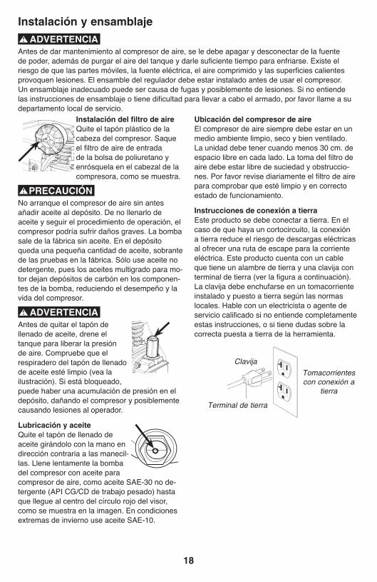
18
Instalación del filtro de aireQuite el tapón plástico de la cabeza del compresor. Saque el fi ltro de aire de entrada de la bolsa de poliuretano y enrósquela en el cabezal de la compresora, como se muestra.
PRECAUCIÓNNo arranque el compresor de aire sin antes añadir aceite al depósito. De no llenarlo de aceite y seguir el procedimiento de operación, el compresor podría sufrir daños graves. La bomba sale de la fábrica sin aceite. En el depósito queda una pequeña cantidad de aceite, sobrante de las pruebas en la fábrica. Sólo use aceite no detergente, pues los aceites multigrado para mo-tor dejan depósitos de carbón en los componen-tes de la bomba, reduciendo el desempeño y la vida del compresor.
ADVERTENCIAAntes de quitar el tapón de llenado de aceite, drene el tanque para liberar la presión de aire. Compruebe que el respiradero del tapón de llenado de aceite esté limpio (vea la ilustración). Si está bloqueado, puede haber una acumulación de presión en el depósito, dañando el compresor y posiblemente causando lesiones al operador.
Lubricación y aceiteQuite el tapón de llenado de aceite girándolo con la mano en dirección contraria a las manecil-las. Llene lentamente la bomba del compresor con aceite para compresor de aire, como aceite SAE-30 no de-tergente (API CG/CD de trabajo pesado) hasta que llegue al centro del círculo rojo del visor, como se muestra en la imagen. En condiciones extremas de invierno use aceite SAE-10.
Instalación y ensamblaje
ADVERTENCIAAntes de dar mantenimiento al compresor de aire, se le debe apagar y desconectar de la fuente de poder, además de purgar el aire del tanque y darle sufi ciente tiempo para enfriarse. Existe el riesgo de que las partes móviles, la fuente eléctrica, el aire comprimido y las superfi cies calientes provoquen lesiones. El ensamble del regulador debe estar instalado antes de usar el compresor. Un ensamblaje inadecuado puede ser causa de fugas y posiblemente de lesiones. Si no entiende las instrucciones de ensamblaje o tiene difi cultad para llevar a cabo el armado, por favor llame a su departamento local de servicio.
Ubicación del compresor de aireEl compresor de aire siempre debe estar en un medio ambiente limpio, seco y bien ventilado. La unidad debe tener cuando menos 30 cm. de espacio libre en cada lado. La toma del fi ltro de aire debe estar libre de suciedad y obstruccio-nes. Por favor revise diariamente el fi ltro de aire para comprobar que esté limpio y en correcto estado de funcionamiento.
Instrucciones de conexión a tierraEste producto se debe conectar a tierra. En el caso de que haya un cortocircuito, la conexión a tierra reduce el riesgo de descargas eléctricas al ofrecer una ruta de escape para la corriente eléctrica. Este producto cuenta con un cable que tiene un alambre de tierra y una clavija con terminal de tierra (ver la fi gura a continuación). La clavija debe enchufarse en un tomacorriente instalado y puesto a tierra según las normas locales. Hable con un electricista o agente de servicio califi cado si no entiende completamente estas instrucciones, o si tiene dudas sobre la correcta puesta a tierra de la herramienta.
Tomacorrientes con conexión a
tierra
Terminal de tierra
Clavija

19
ADVERTENCIAUna conexión a tierra inadecuada puede provocar una descarga eléctrica. Si necesita reparar o cambiar el cable o la clavija, no conecte el alambre de tierra a ninguna de las terminales planas. El alambre de tierra es el de color verde, con o sin franjas amarillas. Si no entiende completamente las instrucciones de conexión a tierra, o si tiene dudas sobre la correcta puesta a tierra de la her-ramienta, hable con un electricista o agente de servicio califi cado. No modifi que la clavija que viene con el equipo; si no puede enchufarla en el tomacorriente, llame a un electricista para que cambie el tomacorriente.
Este producto está diseñado para trabajar en un circuito con un voltaje nominal de 120 volts y está dotado de fábrica con un cable y clavija que permiten su conexión a un circuito eléctrico apropiado. Asegúrese de que el producto esté conectado a un tomacorriente con la misma confi guración que la clavija. No se debe usar un adaptador con este equipo. Si se debe conectar el equipo a un circuito eléctrico de diferente tipo, consiga la ayuda de personal califi cado.
Extensiones eléctricasSólo utilice una extensión eléctrica de tres alambres con una clavija aterrizada de tres terminales que pueda enchufarse en un tomacorriente de tres orifi cios. Asegúrese de que su extensión eléctrica esté en buenas condiciones. Si utiliza una extensión, compruebe que sea de la capacidad de corriente que requiere su equipo. Las product is factory tested to ensure proper operation and performance.
Procedimiento inicial de preparaciónNo se requiere un procedimiento inicial de preparación. Este producto ha sido probado en la fábrica para asegurar su operación y desempeño adecuados.
Instalación y ensamblaje
NOTAS

20
Procedimiento diario de arranque➀ Ponga el interruptor Auto-On/Off en la posición de apagado (Off).
➁ Compruebe visualmente que el compresor no tenga daños ni obstrucciones.
➂ Cierre la válvula de drenado.
➃ Revise el nivel de aceite de la bomba.
➄ Enchufe la manguera de aire al conector de acoplamiento rápido de la unidad del regulador. El collarín del conector de acoplamiento rápido saltará para adelante, sujetando el enchufe y efectuando un sello entre el conector y el enchufe. Para desconectar la manguera de aire, empuje hacia atrás el collarín del conector de acoplamiento rápido.
➅ Enchufe el cable de corriente en un tomacorriente apropiado.
Procedimientos de operación➆ Mueva el interruptor Auto-On/Off a la posición de encendido (Auto-On); el compresor deberá arrancar, acumulando presión de aire en el tanque hasta llegar a la presión de apagado, momento en el cual se apagará de manera automática.
➇ Ajuste el regulador a la presión de aire recomen dada para su aplicación, cerciorándose de que está dentro de las normas de seguridad para llevar a cabo la tarea. En el caso de herramientas neumáticas, el manual del fabricante debe tener recomendaciones sobre su presión de operación.
Nota: Ahora el compresor de aire está listo para serusado. Los siguientes accesorios de infl ado y limpieza, los cuales vienen con esta unidad, sólo se deben operar a una presión máxima de 20-30 PSI: soplete (y su adaptador), boquilla cónica, agujas de infl ado.
!
147
5
6
3
8
Procedimiento diario de apagado1. Ponga el interruptor en la posición de apagado (Off).2. Desconecte el cable del tomacorriente. 3. Ponga en cero el regulador de presión de salida. 4. Desconecte las herramientas y accesorios. Siempre use protección para oídos y ojos al drenar el tanque. Drene el tanque en un lugar adecuado; en casi todos los casos habrá presencia de condensación en el drenaje. 5. Abra la válvula de drenado permitiendo que escape el aire del tanque. Cuando haya salido del tanque todo el aire, cierre la válvula de drenado para evitar que le entre suciedad.
PRECAUCIÓNAl drenar el tanque utilice protección para oídos y ojos. Drene el tanque en un lugar apropiado; en la mayoría de las ocasiones al drenar saldrá conden-sación.
ADVERTENCIASi no drena el tanque, en su interior quedará agua que lo corroerá y debilitará, lo cual puede provocar su ruptura. Siempre drene el tanque diariamente o después de cada uso.

21
NOTA: Cualquier procedimiento de servicio que no esté cubierto en el programa de manten-imiento que sigue deberá ser efectuado por personal de servicio calificado.
Mantenimiento
Puntos a revisar o cambiar Antes de cada uso o diariamente
Tras las primeras 10
horas
Cada 100 horas
Revisar la válvula de seguridad del tanque
Revisar visualmente el aspecto general de la unidad
Revisar el nivel de aceite
Cambiar el aceite X X
Revisar el fi ltro de aceite (con mayor frecuencia si se trabaja en ambientes polvosos o húmedos
X
Drene el tanque (cada vez que sea usado o diariamente) X
PRECAUCIÓNA fi n de asegurar una operación efi ciente y una larga vida del compresor, debe seguirse un pro-grama de mantenimiento de rutina. El siguiente programa de mantenimiento está enfocado al consumidor cuyo compresor es usado en un medio ambiente normal y con una periodicidad diaria. De ser necesario, el programa se debe modifi car para adecuarlo a las condiciones bajo las cuales se usará su compresor. Los compre-sores em pleados en medios ambientes muy sucios u hostiles requerirán mantenimiento más frecuente.
ADVERTENCIAAntes de dar mantenimiento al equipo, se le debe apagar y desconectar del tomacorriente, así como purgar el aire del tanque y permitir que la unidad se enfríe. Las partes en movimiento, las fuentes eléctricas, el aire comprimido y las superfi cies calientes pueden provocar lesiones.
1. Apague el compresor y desenchufe el cable de corriente. 2. Si el compresor ha estado en operación, permita que se enfríe.3. Abra la válvula de drenado para vaciar el aire del tanque.4. Cierre la válvula de drenado. 5. Quite el tapón de llenado de aceite que se encuentra en la bomba. 6. Quite el visor con una llave de tuercas o de cubo. Deje que drene el aceite en un recipiente adecuado y deseche este contenedor de man
era apropiada. Tal vez haya que inclinar el compresor ligeramente hacia adelante para que salga todo el aceite.7. Vuelva a colocar el visor. NOTA: apriete el visor a un par de apriete de 10 a 12 libras-pulgada. Revise también la colocación del empaque entre el visor y el cárter del compresor. 8. Llene lentamente la bomba del compresor con aceite para compresor de aire, como aceite SAE-30 no detergente (API CG/CD de trabajo pesado) hasta que llegue al centro del círculo rojo del visor. En condiciones de invierno extremas use aceite SAE-10.
Cambio de aceiteEl procedimiento para cambiar el aceite de la compresora es el siguiente:
AlmacenamientoPara almacenar el compresor, asegúrese de hacer lo siguiente:
1. Lleve a cabo el programa de mantenimiento de rutina.2. Apague la unidad y desconecte del tomacorriente la clavija.3. Quite del compresor las mangueras, accesorios y herramientas de aire.
4. Abra la válvula de drenado para drenar el aire del tanque. 5. Cierre la válvula de drenado.6. Guarde el compresor en un lugar limpio y seco.

22
Antes de dar mantenimiento al equipo, se le debe apagar y desconectar del tomacorriente, así como purgar el aire del tanque y permitir que la unidad se enfríe. Las partes en movimiento, las fuentes eléctricas, el aire comprimido y las superfi cies calientes pueden provocar lesiones.
Diagnóstico y corrección de fallas
PROBLEMA POSIBLE CORRECCIÓN
Fuga de aire en la vál-vula de retención o en la válvula de alivio.
Una válvula de retención defectuosa provoca una fuga de aire constante en la válvula de alivio cuando está apagado el compresor teniendo presión de aire. Drene el tanque y quite y limpie o cambie la válvula de retención.
Fugas de aire entre la cabeza y el cilindro.
Compruebe el apriete de los pernos de la cabeza. Si continúa la fuga, llame a un técnico de servicio.
Fuga de aire en la válvula de seguridad.
Opere manualmente la válvula de seguridad tirando del anillo. Si el tanque continúa teniendo una fuga estando la válvula en posición cer-rada, ésta deberá ser cambiada.
La presión indicada en el manómetro de presión.
Si al usar un accesorio hay una caída excesiva de presión, cambie el regulador. regulada cae al usar un accesorio.
NOTA: Ajuste la presión regulada bajo condiciones de fl ujo (mientras se utiliza un accesorio). Es normal que el manómetro indique una caída de presión mínima al comenzar a utilizar la herramienta.
Presión excesiva en el tanque.
Apague el interruptor de encendido. Si la unidad no se apaga, desconéctela del tomacorriente y comuníquese con un técnico de servi-cio.
El motor no arranca. Compruebe que el cable de corriente está enchufado y que el interruptor está encendido. Compruebe que el fusible de la caja de circuitos sea de la capacidad adecuada. Si se ha disparado, restablézcalo y rearranque la unidad. Si el fusible se dispara con frecuencia, revise la válvula de retención o llame a un técnico de servicio.
Asegúrese de que el interruptor de sobrecarga térmica no esté dis-parado. El motor tiene un cortacircuitos térmico integrado que se dispara cuando es necesario para proteger el motor contra los daños debidos alsobrecalentamiento. Fusible fundido o disyuntorDisparado. Para reinicializar la palanca de sobrecarga del motor, coloque el interruptor de presión “ON /OFF” en posición “OFF” y desenchufe la unidad del tomacorriente. Espere 10 minutos (mínimo) para que se enfríe y se reinicialice el cortacircuitos desobrecarga del motor. Después, puede enchufar y arrancar la unidad nuevamente.
Humedad excesiva en el aire de salida.
Saque el agua del tanque drenándolo después de cada vez que se use. En los medios ambientes de alta humedad habrá un exceso de conden-sación; instale fi ltros de agua en su línea de aire.
NOTA:La condensación no es provocada por una falla en el compresor. Com-pruebe que la salida de aire del compresor sea mayor que el consumo de aire de su herramienta.
Fugas de aire en el cuerpo o la soldadura del tanque.
Nunca taladre, suelde o modifi que de ninguna manera el tanque, pues se debilitará. El tanque podría romperse o explotar. El tanque no puede ser reparado. Ya no utilice el compresor de aire.

23
Husky Air Compressor Model 395-226 Parts List
1
2
3
4
5
6
7
8
9
102
11
1213
141516
17
18
19
20
21
22
23
24
2526
27
33
3635
34
37
4243
4445
48
4746
28
40
41 4950
51
52
53
54 49
40
41
55
56
5758
59
60
61 62
63
394041
2838

24
Compresor de aire – Modelo 395-226 - Lista de las piezas# de ref.
# de kit
# de parte Descripción cant.
1 3Tornillo, M6 X 1.0mm X 30mm
4
2 3 Arandela, Cerradura M6 8
3 3 E100227 Cabeza, Cilindro 1
4 1, 3Empaque, Cabeza a placa de válvula
1
5 3 E100228 Placa, Válvula 2
6 3 E100229 Lengüeta de válvula 2
7 1, 3 Empaque, Placa de válvula
1
8 1, 3Empaque, Cilindro a placa de válvula
1
9 2, 3 E101113 Cilindro 1
10 3 Tornillo, SHC M6 x 1.0 x 20MM
4
11 3 Empaque, Cilindro, inferior
1
12 3 Excéntrica para L1 1
13 3 Tuerca, Hexag, M6x1.0 1
14 2, 3 Tornillo, SHC M6 x 1.0 x 20MM
1
15 2, 3 Pistón L1 / Ensamble de biela
1
16 1, 3 Deflector para L1 1
17 3 E100087Tapa, Llenado de Aceite con anillo en o
1
18 3 E100566 Cubierta, Cárter para L1 1
19 3 E100078Conector, Visor trasnpar-ente de aceite c/sello
1
20 3 Tornillo, HFH M5 x 0.8 x 15MM (placa dich amarillo zinc)
4
21 3 Motor/Bomba, L1B2 1
22 3 E100860 Ventilador, Motor F1 125mm
1
23 3Anillo, A presión, Exterior, 15mm
1
24 3 E100247 Condensador, Marcha 1
25 3 E100248 Condensador, Arranque 1
26 3 Arandela, Cerradura dentada, 8mm
2
27 3 Tuerca, M8x1.25, ZDC 6.5MM TALL
10
28 N/A
29 N/A
30 N/A
31 N/A
32 N/A
# de ref.
# de kit
# de parte Descripción cant.
33 E105151Cable, Poder 16/3 tipo AWG SJT 6’ de largo
1
34 4 Base, Filtro de aire 1
35 4 E101613Elemento, Filtro de succión
1
36 4 Cubierta, Filtro, (HUSKY) 1
37 3Ensamble, Motor/Bomba, L1B2 c/Escape RH
1
38 E100809Conexión, Codo, 3/8NPT x 3/8 compresión
1
39Perno, SHC M8 x 1.25 x 16MM (Placa ZDC)
8
40 Arandela, Cerradura, M8 12
41 Arandela, Plana, M8 16
42 5 Férula, 1/4” 2
43 5 Tuerca, Comp, 1/4” 2
44 5Tubo, Despresurizador 1/4” de cobre
1
45 E101362Válvula, Retención, 90 grados a la Izquierda
1
46 6 Tuerca, Comp, 3/8” 2
47 6 Férula, 3/8” 2
48 6Ensamble, Tubo de escape aletado de cobre de 3/8”
1
49Tornillo, HH M8 x 1.25 x 20MM
8
50 E105137 Pie, Caucho, (HUSKY) 4
51 E100098Válvula, Drenaje multivuelta
1
52Soldadura, Tanque 3 galones
1
53 E105135 Velo, (HUSKY) 1
54Tornillo, HFPH M5 x 0.8 x 10mm (Placa ZDC)
6
55 E104311 Asa, barra estabilizadora 1
56 E105139Adherencia, Asa, (HUSKY)
1
57 E102822 Conexión rápida, Acero 1
58 E100971Regulador, 3-Puertos,1/4 NPT
1
59 E102595 Válvula, Seguridad 1
60 E103339Calibrador, Presión, (38mm c/125 PSI R/L)
2
61 E100594Restricción, Cable de poder - 16/3 SJT
2
62 E100957Ensamble, Interruptor, presión (125 PSI)
1
63Alemite, 1/4” mnpt x 35mm
2

25
Compresor de aire – Modelo 395-226 - Lista de las piezas
Nota: Cualquier campo para los números/juegos de piezas que no tengan un número específico de pieza, indica que no está disponible. Las descripciones se proveen solamente como referencias. La columna con el número de juego indica que la pieza ofrecida está disponible como parte de un juego. Una de cada una de las piezas está ofrecida.
Los números de los juegos y las piezas que están incluidos se describen a continuación:
NOTAS
# de kit # de parte Descripción # de
referencia
1 E100959 Juego, Empaque 4,7,8,16
2 E100251 Juego, Pistón - (Nota: ordene el juego de empaque #1, también, cuando ordene este juego) 9,14,15
3 E105154 Juego, Motor/Bomba ensamblado L1B2 c/Escape RH 1 - 27, 37
4 E105153 Juego, Filtro de aire 34-36
5 E104308 Juego, Tubo despresurizador de dobre de 1/4” 42-44
6 E101334 Juego, Tubo de escape aletado de dobre de 3/8" 46-48

GARANTÍADECLARACIÓN DE LA GARANTÍA LIMITADA
MAT Holdings, Inc. garantiza al comprador origi-nal al menudeo que este producto de MAT Hold-ings, Inc. carece de defectos en los materiales y mano de obra y acuerda reparar o reemplazar, a la sola discreción de MAT Holdings, Inc., cual-quier producto defectuoso sin cargo alguno den-tro del plazo establecido después de la fecha de compra:
Dos años si el producto se emplea para uso personal, familiar o doméstico;
90 días si el producto se emplea para cualquier otro propósito, como el uso comercial o el de alquiler.
Esta garantía únicamente se ofrece al comprador original al menudeo y comienza en la fecha de la compra original al menudeo.
Cualquier parte del producto MAT Holdings, Inc. manufacturado o suministrado por MAT Holdings, Inc. que, a juicio razonable de MAT Holdings, Inc. tenga defectos en los materiales o en la mano de obra, será reparado o remplazado por un esta-blecimiento de servicio autorizado de productos MAT Holdings, Inc. , sin cargo alguno al compra-dor por concepto de piezas y mano de obra.
El producto, incluida toda pieza defectuosa, debe enviarse a un establecimiento de servicio autorizado dentro del período de la garantía. El propietario es responsable de pagar los gastos de entrega del producto MAT Holdings, Inc. al establecimiento para cualquier trabajo garan-tizado y también los gastos de devolución de la pieza al propietario después de la reparación o reemplazo. La responsabilidad de MAT Holdings, Inc.ʼs con respecto a todo reclamo se limita a las reparaciones o remplazo del producto, y ningún reclamo de incumplimiento de la garantía será causante de la cancelación o rescisión del con-trato de venta de ningún producto de MAT Hold-ings, Inc. En el establecimiento se requerirá el re-cibo de compra para respaldar cualquier reclamo al amparo de la garantía. Todo trabajo cubierto en la garantía debe ser realizado por un concesion-ario de servicio autorizado de MAT Holdings, Inc.
Esta garantía se limita a noventa (90) días a
partir de la fecha original de la compra de cual-quier producto MAT Holdings, Inc. empleado para propósitos comerciales o de alquiler, o cualquier otro propósito generador de ingresos.
Esta garantía no cubre ningún producto de MAT Holdings, Inc. que haya estado sujeto a abuso,
abandono, negligencia o accidente, o que se haya utilizado en alguna manera de forma con-traria a las instrucciones de funcionamiento según se especifi ca en este manual del opera-dor . Esta garantía no aplica a los daños en el producto de MAT Holdings, Inc. que resulten de un mantenimiento indebido ni a producto alguno de MAT Holdings, Inc. que haya sido alterado o modifi cado. La garantía no cubre las reparacio-nes que resulten necesarias por el desgaste nor-mal o por el uso de piezas o accesorios que sean incompatibles con el producto de Mat Holdings, Inc. o que afecten adversamente su funciona-miento, desempeño o durabilidad.
MAT Holdings, Inc. se reserva el derecho a cam-biar o mejorar el diseño de cualquier producto de MAT Holdings, Inc. sin asumir ninguna obligación de modifi car ningún producto fabricado previa-mente.
TODAS LAS GARANTÍAS IMPLÍCITAS ESTÁN LIMITADAS EN DURACIÓN SEGÚN EL PERÍO-DO DE GARANTÍA DECLARADA. POR CON-SIGUIENTE, CUALQUIER GARANTÍA IMPLÍCI-TA, INCLUSO LAS DE COMERCIABILIDAD, IDONEIDAD PARA UN PROPÓSITO EN PAR-TICULAR, O DE CUALQUIER TIPO, PIERDEN TOTALMENTE SU VALIDEZ DESPUÉS DEL VENCIMIENTO DEL PERÍODO DE GARANTÍA CORRESPONDIENTE DE DOS AÑOS O NO-VENTA DÍAS. DE CONFORMIDAD CON ESTA GARANTÍA, LA OBLIGACIÓN DE MAT Hold-ings, Inc., SE LIMITA ESTRICTA Y EXCLUSIVA-MENTE A LA REPARACIÓN O REMPLAZO DE LAS PIEZAS DEFECTUOSAS, Y MAT Holdings, Inc., NO ASUME NINGUNA OTRA OBLIGACIÓN, NI AUTORIZA A NADIE ASUMIRLA A NOMBRE DE DICHA COMPAÑÍA. ALGUNOS ESTADOS NO PERMITEN LIMITACIONES EN CUANTO A LA DURACIÓN DE UNA GARANTÍA IMPLÍCITA, POR LO CUAL ES POSIBLE QUE LA LIMITACIÓN ANTERIOR NO SE APLIQUE EN EL CASO DE USTED. MAT Holdings, Inc. NO ASUME NINGU-NA RESPONSABILIDAD POR DAÑOS DIREC-TOS, INDIRECTOS O DE NINGÚN OTRO TIPO, COMO EL GASTO DE ENVIAR EL PRODUCTO DE MAT Holdings, Inc. A UN ESTABLECIMIEN-TO DE SERVICIO AUTORIZADO Y EL GASTO DE ENVIARLO DE ALLÍ AL PROPIETARIO, EL TIEMPO DE VIAJE DEL MECÁNICO, CARGOS TELEFÓNICOS O TELEGRÁFICOS, ALQUILER DE UN PRODUCTO SUSTITUTO DURANTE EL TIEMPO DE REALIZACIÓN DEL SERVICIO DE LA GARANTÍA, VIAJES, PÉRDIDA O DAÑOS A OBJETOS DE PROPIEDAD PERSONAL, PÉR-DIDA DE INGRESOS, PÉRDIDA DEL USO DEL
26

PRODUCTO, PÉRDIDA DE TIEMPO O INCON-VENIENTES. EN ALGUNOS ESTADOS NO SE PERMITE LA EXCLUSIÓN O LIMITACIÓN DE DAÑOS DIRECTOS O INDIRECTOS, POR LO CUAL ES POSIBLE QUE LA LIMITACIÓN O EX-CLUSIÓN DESCRITA ARRIBA NO SE APLIQUE EN SU CASO.
Esta garantía le confi ere derechos legales es-pecífi cos, y es posible que usted goce de otros derechos, los cuales pueden variar de estado a estado.
Esta garantía se aplica a todos los productos de MAT Holdings, Inc. fabricados o vendidos por di-cha compañía en Estados Unidos y Canadá.
Para encontrar el concesionario de servicio autor-izado más cercano a used, llame al 1-888-859-4549.
27