owner's manual - · pdf file1. introduction ... regulations and laid down by the colreg....
TRANSCRIPT

w w w . c a t a - l a g o o n . c o m
L A G O O N 6 2 0EN
O W N E R ' S M A N U A L

2

3
1. INTRODUCTION ................................................................................................................................................ 4
2. SPECIFICATIONS .............................................................................................................................................. 6
2.1. Identifi cation sheet of your boat ....................................................................................................................... 6
2.2. Dimensions ................................................................................................................................................................ 6
2.3. Load ............................................................................................................................................................................. 7
2.4. Rigging & sails .......................................................................................................................................................... 9
3. SAFETY................................................................................................................................................................. 12
3.1. Fire ................................................................................................................................................................................ 12
3.2. Visibility ...................................................................................................................................................................... 15
3.3. Stability, danger of infi ltration ............................................................................................................................ 15
3.4. Prevention of man overboard ............................................................................................................................ 16
3.5. Liferaft (not provided) ........................................................................................................................................... 17
4. EQUIPMENT ....................................................................................................................................................... 18
4.1. Motorization ............................................................................................................................................................. 18
4.2. Steering system ....................................................................................................................................................... 19
4.3. Electrical system ...................................................................................................................................................... 20
4.4. Gas and fresh water system ................................................................................................................................. 26
4.5. Waste holding tanks ............................................................................................................................................... 28
4.6. Pumps, valves and sea-cock fi ttings ................................................................................................................. 30
5. ANCHORING, MOORING AND TOWING ................................................................................................ 32
6. HOISTING AND TRANSPORT ..................................................................................................................... 33
7. REFERENCES AND STANDARDS ............................................................................................................... 34
Updated 12.2015
OWNER'S MANUAL
CO N T E N T S

4
Dear Sir / Madam,
You have just taken delivery of your new LAGOON and, fi rst of all, we thank you for the trust you have shown in buying a boat of our brand.
A LAGOON is made to last. From its design to its construction and eventually to its launching, every boat, including the smallest details, is considered with the very care it deserves in order to ensure you the years of joy you expect.
This manual is intended to help you enjoy your boat in safety. It includes many details about the boat specifi cations, the provided or installed equipment and also information on how to use it. Read it carefully and familiarize yourself with the boat before sailing.
This Owner's manual is not a course on safety at sea or good sailing sense. If this is your fi rst boat, or if you are changing to a new type of boat with which you are not familiar with, both for your comfort and your safety, we would advise you to obtain some training before taking the helm of your new boat. Your retailer, your national sailing or motor boat federation or your yacht club would be delighted to inform you about the local sailing schools or skilled instructors in the area.
Make sure that the forecast wind and sea conditions match with the build category of your boat, and that you and your crew are capable of sailing safely your boat in such conditions. Even when your boat is suited, the sea and wind conditions corresponding to the build categories A, B and C may vary from heavy storm for the A category to severe conditions for the C category. These situations, during which may occur exceptional waves and gusts, are therefore dangerous and only an experienced crew, well trained and prepared is able to sail a boat, provided it is properly maintained.
This Owner's manual is not a course in maintenance and repair. In case of diffi culty, do not hesitate to ask your builder or representative. If a maintenance manual is provided, do not hesitate to
use it. Always ask an experienced professional for the maintenance or your boat, for the installation of further accessories or for any modifi cation. Any modifi cation which may alter the safety specifi cations of the boat have to be estimated, carried out and documented by qualifi ed people. The builder can not be liable for modifi cation that would not have been approved.
Please note that, in some countries, a sailing license or authorization is required or specifi c regulation has to be observed.
Always keep your boat correctly maintained and take into account the damages due to time or, if applicable, due to an intensive or inappropriate usage of the boat. Any boat, as solid as it can be, may be severely damaged if not sailed properly. This is not compatible with a safe sailing experience. Always adapt the speed and the direction of the boat to the sea conditions.
If your boat is fi tted with a life raft, read carefully its user's guide. It is necessary that the crew can fi nd on board all the safety equipment (life jacket, harness, etc.) corresponding to the boat, to the weather conditions, etc. This equipment has been made mandatory by some countries. It is necessary for the crew to be familiarized with the use of all the safety equipment and with the emergency safety procedures (MOB, towing, etc.). Sailing schools and yacht clubs often off er training sessions.
It is recommended that everybody wears appropriate safety equipment (life jacket, individual buoyancy aids) when they are on the deck. Please note that, in some countries, always wearing a buoyancy aid in conformity with the local standards has been made compulsory.
1

5
The users of this boat are informed that:
All the crew members have to be properly trained.Do not sail at maximum speed in areas of dense traffi c or in case of reduced visibility, strong winds or high waves. Reduce the speed and the wake of the boat, by respect to others but also as a measure of safety, both for them and for yourself. Respect the speed and wake limits when zones are defi ned. Respect the priority rules set by the navigation regulations and laid down by the COLREG.Make sure that you always have a suffi cient distance to stop or steer the boat in order to avoid a collision.
The diff erent warning used throughout this guide are as follow :
x DANGER
Warns you about the existence of an extreme hazard that is very likely to induce serious or fatal consequences if the appropriate precautions are not taken.
WARNING
Warns you about the existence of a hazard that may have serious or fatal consequences if the appropriate precautions are not taken.
! ATTENTION
Warns you about safety practices or draw your attention to dangerous practices that may hurt people or caused damages to the boat, its components or to the environment.
KEEP THIS MANUAL IN A SAFE PLACE AND PASS IT TO THE NEW OWNER SHOULD YOU SELL THE BOAT.
I N T R O D U C T I O N

6
2.1 . Identifi cation sheet of your boat :
Number of people recommended per build category
WARNING
Do not overcome the recommended maximum number of people. Regardless of the number of people on board, the total weight of the people and of the equipment should not exceed the maximum recommended load. Always use the seating provided.
* according to ISO 8666
NAME OF THE BUILDER CONSTRUCTION NAVALE BORDEAUX
BUILD CATEGORY A
MAXIMUM RECOMMENDED POWER
2 X 110CV (2 X 81 KW)
CERTIFYING ORGANISATION NUMBER CE0607
2. SPECIFICATIONS
CategoryMaximum number
of people
A 14
B 14
C 16
D 30
CategoryWave height
(m)Wind force (Beaufort)
A > 4 > 8
B < 4 ≤ 8
C < 2 ≤ 6
D < 0.5 ≤ 4
LENGTH OF THE HULL 18,20 m*
HULL BEAM 10,00 m*
MAXIMUM LENGTH 18,90 m
MAXIMUM BEAM 10,00 m
KEEL DRAUGHT 1,55 m
MAXIMUM HEIGHT 31,00 m
Builder's plate: certain information is given on the builder's plate fi xed to the boat.
You will fi nd an extensive explanation of this information in the dedicated chapter of this manual.
REMINDER OF THE CATEGORIES
Category A: the boat is designed for sailing in winds that may exceed force 8 on the Beaufort Scale and in waves of a signifi cant height of 4 m or more and the boat is to a large extent self - suffi cient. Unusual conditions such as hurricanes are excluded. You may meet with such conditions when sailing long crossings, for instance across the oceans, or close to the shore when you are not protected from the winds and waves over several hundreds of nautical miles.
Category B: the boat is designed for sailing in winds that may not exceed force 4 on the Beaufort Scale and in corresponding waves (waves of a signifi cant height of 4 m or less (see Note 1 below). You may meet with such conditions when sailing at open sea during quite a suffi cient time, or close to the shore when you are not protected from the winds and waves over several dozens of nautical miles. You may also meet with such conditions when sailing quite important inland seas which could produce waves of this height.
Category C: the boat is designed for sailing in winds that may not exceed force 6 on the Beaufort Scale and in corresponding waves (waves of a signifi cant height of 2 m or less (see Note 1 below). You may meet such conditions when sailing exposed inland waters, estuaries and inshore waters with moderate weather conditions.
Category D: the boat is designed for sailing in winds that may not exceed force 8 on the Beaufort Scale and in corresponding waves (occasional waves of 0.5 m maximum (see Note 1 below). You may meet such conditions when sailing non exposed inland waters and inshore waters under good weather conditions.
NOTE 1 - The signifi cant height of a wave is the average height of the upper third of the waves, which corresponds more or less to the height an experienced observer can assess. Some waves will be twice as high as this value.
The sails are the principal means of propulsion of the Lagoon 620.
The Lagoon 620 is in conformity with the Directive 2003 44 CE .
2.1 . Dimensions
2

7
2.3 . Charge
NAVIGATION CATEGORIES A B C D
Light boat: 29 960 29 960 29 960 29 960
Safety equipment 50
Sail 410
Light displacement 30 520
Life-raft: (2) 160
Crew 1 050 1 050 1 200 2 250
Water 960
Fuel 1 040
Supplies and personal belongings:
ICNN instruction : 30kg minimum Cat
A, 20kg Cat B, 10kg Cat C, 5kg
Cat D
420 280 160 200
Optional equipment A B C D
Anchoring (anchors + chain + anchor
chain)500
Spinnaker rigging + spinnaker 60
Gennaker rigging + spinnaker 60
Electric genoa sheet winch x2 64
Electric genoa sheet winch x2 52
Lazy bag + Lazy jack 13
Canvas surround with windows 18
Supplementary swimming ladder 7
Davits 350
Tenderlift 350
Teck option 235
Sunbathing cushion 7
Forward and aft cockpit cushion 35
2nd cockpit deck shower 2
Inlet valve for shore freshwater 2
Microwave oven 17
Dishwasher 28
Replacement with coolbox or supple-
mentary fridge15
Watermaker ( x2) 130
Icemaker 18
Replacement with coolbox or supple-
mentary fridge75
Ventilators in the saloon 2
Ventilators in the cabins 2
Heating (not compatible with air
conditionning)56
Air conditionning 250
S P E C I F I C AT I O N S

8
NAVIGATION CATEGORIES A B C D
Berth cabin in port bow 60
Berth cabin or bathroom in starboard
bow50
Entry door curtain 3
2 battery chargers 100 A 18
Inverter 12 V / 220 V 8
Genset + cocon 17 KVA - 220 V 450
Dual engine controls 12
Antifouling 88
Laser loader radio + 2 speakers 3
Cockpit watertight loudspeaker (x4) 2
VHF 1
GPS 2
Electronics:
Speedometer/depth sounder/plotter5
Autopilot 10
Radar 3
Mooring lines and fender 50
Tenders + engine 450
Diving equipment 120
Others 450
MAXIMUM LOAD DISPLACEMENT (kg) 38 290 38 150 38 180 40 020
MAXIMUM LOAD (kg) 7 770 7 630 7 660 9 500
MAXIMUM LOAD = maximum load displacement - light boat
The recommended maximum load includes the weight of all people on board, of the supplies and personal belongings, of all the equipments which are not included in the weight of the light boat, of the freight (if applicable) and of all the consumable liquids (water, fuel, etc. ).
WARNING
When loading the boat, you should never exceed the recommended maximal load. You should always load the boat with caution and distribute the loads thoroughly in order to preserve the theoretical trim (approximately horizontal). Avoid placing heavy loads in the upper storage space.
2

9
VOILE SURFACE Dimensions
MAIN SAIL 146 m2 I 25.36 m
GENOA (MAXI) 97 m2 J 6,289 m
STAYSAIL 51 m2 P 24,7 m
GENNAKER 175 m2 E 8,26 m
SPINNAKER 300 m2
P
LP
PI
J
E
2.4 . Rigging & sails
2.4.2 . Maintenance of the rigging:
Regularly check the standing and running rigging, at least once a year.
Considering the metal cables:Have them changed as soon as the fi rst rust-spot appears. Check for corrosion, particularly at connections with the turnbuckles. Check that the end fi ttings and the turnbuckles are in good condition.
Considering the synthetic ropes of the backstays, halyards, sheets, mooring lines, etc.: Have them changed as soon as the fi rst signs of wear and tear or chafi ng appear.Regularly check the other parts of the rigging, sheets, mooring lines, etc. and have them replaced if worn.
2.4.1 . Sails specifi cations:
S P E C I F I C AT I O N S

10
2.4.3 . Mast handling diagram
1 - Spinnaker / gennaker halyard (option)2 - Mainsheet3 - Reef pendant 34 - Luff pendant - reef 35 - Mainsail topping lift6 - Reef pendant 17 - Reef pendant 28 - Main halyard
9 - Luff pendant - reef 110 - Luff pendant - reef 211 - Staysail sheet12 - Genoa sheet13a-b - Spinnaker / gennaker sheet + spinnaker guy14a - Portside control lines for mainsheet traveller14b - Starboard control lines for mainsheet traveller
2

11
SAIL REDUCTION
ATTENTION
Any adjustment diff ering from these instructions may cause the rupture of the mast. In particular, the 100% genoa with 2 reefs in the mainsail must be absolutely avoided.
MAX. TRUE WIND
WIND KNOTS SAILS
FORCE 1 - 4 20 MAINSAIL 100 %
GENOA 100%
WIND KNOTS SAILS
FORCE 5 25 MAINSAIL 1 REEF
GENOA 85%
WIND KNOTS SAILS
FORCE 6 30 MAINSAIL 1 REEF
GENOA 70 %
OR STAYSAIL 100%
WIND KNOTS SAILS
FORCE 7 35 MAINSAIL 2 REEFS
STAYSAIL 85 %
WIND KNOTS SAILS
FORCE 8 40 MAINSAIL 3 REEFS
GENOA 40%
WIND KNOTS SAILS
FORCE 9 45 MAINSAIL 3 REEFS
GENOA 30%
!
S P E C I F I C AT I O N S

12
1
1 2 3
Version cuisine / coque
1 2 3
Version cuisine / carré
1 - Fixed extinguishing system for the engine bilge.
1 - Cut off device of generator tank fuel supply (portside).
2 - Release mechanism of portside engine bilge extinguisher.
3 - Cut off device of portside tank fuel supply.
1 - Cut off device of portsidetank fuel supply.
2 - Release mechanism of portside engine bilge extinguisher.
3 - Cut off device of generator tank fuel supply (portside).
Access by the pull handles under the hob in the gallery in the portside hull aft
Access by the pull handles behind the hatch under the bedside storage at the aft end of the port hull.
4 5
4 - Release mechanism of starboard engine bilge extinguisher.
5 - Cut off device of starboard tank fuel supply.
Access through the hole behind the WC in the starboard hull aft.
Access in the engine bilges.
3.1 . Fire
3.1.1 . Risks
3.1.2 . Fire fi ghting equipment
Portable extinguishers: to be provided by the owner. The enforcement of the national regulation under the fl ag of which you are sailing is your responsibility. The boat, when sailing, must be fi tted with portable extinguishers.
We advise you to provide at least 1 extinguisher within a 5 meter distance to each berth, within a 2 meter distance of the extinguisher access hole to the engine compartment, within a 2 meter distance to every appliance using a naked fl ame and, eventually, 1 extinguisher within 1 meter of the steering wheel.
We advise a total capacity of at least 8A / 68B for all the portable extinguishers, each of them with a least a capacity of 5A / 34B. The CO2 extinguishers have to be used for the kitchen or electrical fi res.
The boat is delivered with 1 CO2 extinguisher in every engine compartment.The location is defi ned in the diagram below. This location is the same for any of the 3 versions.
3. SAFETY
The main risks are related to the motorization (§4.1), to the electrical system (§4.3) and to the gas system (§4.4).
Please refer to the appropriate sections.
Galley / hull version Galley / saloon version
3

13
1
4
3
4
3
2
1
2
3
1
1 - Emergency exit.2 - Extinguisher.3 - Release pull handle of engine extinguisher.4 - Engine extinguisher. 5 - Distress fl ares.6 - First aid kit.7 - VHF (optional).8 - ...........................................................................9 - ...........................................................................10 - .........................................................................11 - .........................................................................12 - .........................................................................13 - .........................................................................14 - .........................................................................15 - .........................................................................16 - .........................................................................
Version cuisine / coque
Version cuisine / carré
3.1.3 . EMERGENCY EXITS
The recommended emergency exits are indicated on the opposite diagram:
RECOMMENDATIONS
Some elements do not have pre-determined location.Fill-in this diagram with your own safety equipment.
Galley / hull version
Galley / saloon version
S A F E T Y

14
General points
WARNING
Do not install free hanging curtains or any other textile next to or over the cooking appliances or any other naked fl ame devices.Ensure the bilges remain clean and check regularly there is no vapor or leaks of fuel and gas.
Do not store fl ammable products in the engine compartment.
Do not leave the boat unsupervised when using cooking and or heating devices.Do not smoke while handling fuel or gas.
Make sure the fi re fi ghting equipment can be reached easily when people are on board. Inform the crew of:• the location and functioning of the fi re fi ghting
equipment.• the location of discharge valves in the engine
compartment.• the location of routes and exits.In case you had to replace some elements of the fi re fi ghting equipment, only use appropriate appliances, bearing the same reference or having similar technical specifi cations and fi re resistance.
If non fl ammable products are stored in the engine compartment, they must be stored in order not to fall on the machinery and they should not prevent neither the entrance nor the exit of the engine compartment.■ Do not block the way out nor the hatchways.■ Do not block the safety control such as: fuel
valves, gas valves, electrical system switches.■ Do not block the access to the portable
extinguishers fi tted in the cupboards.
■ Do not use gas lamp in the boat.■ Do not alter any equipment on board (especially
the electrical, fuel and gas systems) nor allow non qualifi ed people to alter any equipment of the boat.
■ Do not fi ll up the fuel tanks nor the gas cartridges when the engine is running or when cooking or heating devices are in use.
Fire fi ghting equipment maintenance
It falls to the owner / user: To have the fi re fi ghting equipment regularly checked, respecting the frequency indicated on the equipment■ If the portable fi re fi ghting equipment has passed
its use-by date or if it is discharged, to replace it with devices of same or superior extinguishing capacity.
■ If the fi xed extinguishing systems have passed their use - by date or if they are discharged, to have them fi lled up or replaced.
3

15
3.2 . Visibility
Visibility from the command post may be hindered because of extreme leaning due to the boat's trim or because of other factors linked to one or several of the following conditions:
• Load and load distribution• Speed• Sea conditions• Rain and spray• Obscurity and fog• Light in the boat• Position of the upper or lateral awnings• People or removable equipment in the helmsman's
fi eld of view • In motor-driven boats, rapid acceleration or
transition from drive-limit to hydroplaning• Angle of the trim regulator with regard to the
engine (for the boats equipped)
• Angle of the trim regulator with regard to the hull (for the boats equipped)
• Sailing heel, the sails reducing the visibility leeward.
The international regulation to prevent collisions at sea (COLREG) and course regulations make mandatory a permanent and proper supervision and the observance of priority. To observe these rules is essential.
3.3 . Stability, danger of infi ltration
Reduce your speed before making tight bends in
order to avoid losing control.
While sailing, keep every porthole, window and removable door closed.Stability is reduced when upper storage spaces are loaded.Stability may be reduced when another boat is towed or when heavy weights are lifted with the davits or the boom. Breaking waves are serious dangers both for stability and water infi ltration. Fasten the doors and hatchways in case of rough seas.Never sail a boat with a negative trim adjustment (low stem) when sailing high speed.
This can induce the boat to heel over and therefore cause an instability in the turns. Use a negative trim when going from limit speed to hydroplaning and at lower speed in the chop.The compartment marked as being air pockets should not be pierced.If your boat is certifi ed as unsinkable, it is capable of bearing its passengers, even in case of infi ltration.On boats where a bilge pump is not required, it is the responsibility of the user / owner to have on board at least a bucket / bailer equipped with a mean to prevent its loss overboard.
S A F E T Y

16
3
3.4 . Prevention of man overboard
The swimming ladder is removable. It is stored in the aft cockpit locker. The deck areas which are not considered as being
part of the working deck and which should not be used when sailing are hatched on the diagram below.
Regularly check the lifelines:Considering the metal lifelines, check the appearance of rust-spots and corrosion, particularly at connection points.
Considering the synthetic lifelines, have them changed as soon as the fi rst signs of wear and tear appear because of chafi ng or of UV.

17
1 - Location for life buoy.2 - Deck eye for life line fastening.3 - Emergency tiller.4 - Emergency tiller cover.5 - Location for life raft.6 - Manual bilge pump.
7 - Extinguisher.8 - .........................................9 - .........................................10 - .......................................11 - .......................................12 - .......................................
5
3
2
222
2
222
2
6
6
6
6
4
1
1
4
5
S A F E T Y
3.5 . Life raft (not provided) Carefully read its user's guide.
Security equipment location (to complete with your own safety equipment if necessary).
18
4
For more information on the fi tted devices, read the provided manuals attached to the boat documentation.
4.1 . Motorization
4.1.1 . Directions for use
Do not install on this boat a heavier or more powerful engine than what has been recommended: this may induce a risk for the stability.Stop the engine. Do not smoke when fi lling up the fuel tank.For outboard engines fi tted with a jerrican, fi ll up the portable tank outside the boat in a well ventilated area, far from any fi re risk.Fuel stored somewhere else than in the tanks (jerricans, feed tanks...) must be kept in a ventilated place.Before starting, ensure that the engine hold is clean and dry. Any trace of fuel in the bilges should make you postpone your departure.Avoid any contact between fl ammable products and hot parts of the engine.Locate the extinguisher access hole which would allow you to knock down a fi re in the engine hold. For boats equipped with a petrol engine, ventilate the engine compartment using the engine blower during 4 minutes in order to evacuate any possible petrol vapors.For certain models, a fi xed extinguisher system, allowing knocking down a fi re in the engine hold, is provided. Learn where to fi nd its activation switch and how it works (see 3.1.2). It is necessary to ventilate the engine hold after having used it.Check that the apertures for ventilation are clear of any obstruction.Do not block nor modify the ventilation system.
Before starting, ensure that: - the engine control is not engaged,- the water control intake valve of the cooling
system is open and check that there is some water actually coming out of the exhaust when the engine has started (water may be mixed with exhaust gas in case of wet exhaust).
It is not recommended to work on moving parts or next to them (engine, line shaft, etc.).
If an intervention is made necessary:- stop the engine and or the rotation of the line
shaft before working on one of their parts.- beware of loose - fi tting clothing, hair, rings which
may get caught up. Wear appropriate clothes (gloves, hat, etc.).
If equipped with a petrol engine, beware of the danger of falling asleep because of carbon dioxides fumes.In case of fuel spillage on the deck when fi lling up, have it cleaned before starting.Anticipate the deterioration of fuel pipes.Fuel hoses have to be replaced by hoses bearing the same markings.
4. EQUIPMENT

19
1
4
6
3
5
2
7
8
1 - Fuel tanks.2 - Fuel closing pull handle.3 - Sea water fi lter.4 - Fuel fi lter.5 - Engine water inlet valve .6 - Engine.7 - Expansion tank.8 - Diesel oil tank fi llers.
Each hull has the same components.
Nota : each valve in the boat is identifi ed.
E Q U I P M E N T
4.1.2 . Fuel tanks: 2x650 liters DIESEL
4.2 . Steering systemThe steering system is hydraulic.
A BC
D
FLY
COQUEHULL
20
2
1
3
4
4
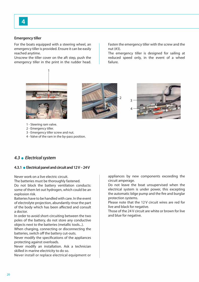
Emergency tiller
For the boats equipped with a steering wheel, an emergency tiller is provided. Ensure it can be easily reached anytime. Unscrew the tiller cover on the aft step, push the emergency tiller in the print in the rudder head.
Fasten the emergency tiller with the screw and the nut (#3).The emergency tiller is designed for sailing at reduced speed only, in the event of a wheel failure.
4.3.1 . Electrical panel and circuit and 12 V – 24 V
Never work on a live electric circuit.The batteries must be thoroughly fastened.Do not block the battery ventilation conducts: some of them let out hydrogen, which could be an explosion risk.Batteries have to be handled with care. In the event of electrolyte projection, abundantly rinse the part of the body which has been aff ected and consult a doctor.In order to avoid short-circuiting between the two poles of the battery, do not store any conductive objects next to the batteries (metallic tools...).When charging, connecting or disconnecting the batteries, switch off the battery cut-outs.Never modify the specifi cations of the appliances protecting against overloads.Never modify an installation. Ask a technician skilled in marine electricity to do so.Never install or replace electrical equipment or
appliances by new components exceeding the circuit amperage.Do not leave the boat unsupervised when the electrical system is under power, this excepting the automatic bilge pump and the fi re and burglar protection systems.Please note that the 12 V circuit wires are red for live and black for negative.Those of the 24 V circuit are white or brown for live and blue for negative.
4.3 . Electrical system
1 - Steering ram valve.2 - Emergency tiller.3 - Emergency tiller screw and nut.4 - Valve of the ram in the by-pass position.

21
24 V PANEL GENERAL BOARD CUT OUT
E Q U I P M E N T
24 V CIRCUIT

22
4
12 V CIRCUIT

23
12
3
4 5
6
6
E Q U I P M E N T
4.3.2 . 110 V - 220 V Electrical system
Some boats are fi tted with a 110 V or 220 V circuit (in their standard version or as an option according to the model).It is necessary to observe the following rules in order to avoid electric shocks and fi re: Never work on the live electric circuit.
Connect the boat shore supply cable in the boat
before plugging it to the shore supply socket.
Never let the end of the boat shore supply cable
fall into the water.
When the shore supply socket is plugged, there
could be a diff erence between the "earth" on the
boat and the one of the power grid. This could
create a danger of electrical cross - currents and
therefore electrocution (particularly for nearby
swimmers).
Turn off the shore power with the cut off device
fi tted on board before plugging or unplugging
the boat shore supply cable.
Unplug the boat shore supply cable fi rst on the
shore side.
If the reverse polarity indicator is on,
immediately unplug the cable. Solve the
polarity problem before using the electrical
system of the boat.
Thoroughly close the shore socket cover.
Do not modify the connections of the boat / shore
supply cable; only use compatible connections.
Do not modify the boat electrical system nor the relevant diagrams. It is necessary that any modifi cation and maintenance are carried out by a technician skilled in marine electricity. Have the system checked at least twice a year.Unplug the boat's supply when not in use, in order to avoid any fi re risk.Connect the electrical appliances metallic covers or boxes to the protective conductor of the boat (green conductor with yellow stripes).Only use electrical devices with double insulation or earth.Please note that live wires are blue, neutral wires are brown and earth wires are green and yellow.
1 - 110 V - 220 V protection panel.2 - 110 V - 220 V selection panel.3 - Starting / stop control of the converter.4 - Starting / stop control of the watermaker (optional).5 - Starting / stop control of the generator.6 - Household appliances circuit breakers.

24
1 2
4
4.3.3 . Emergency starting
If the engine batteries are not available, a coupling system of the port and starboard 12 V starting batteries is available (in the engine compartment port side).
To select the battery coupling:- Activate (ON position) the general cutout, the
starboard and port side engine cut outs and then the coupling cut out located in the engine compartment port side.
- Start the engines, both port and starboard sides.- When both engines have started, switch off (OFF
position) the coupling cut out.
Please note: in a normal confi guration, the 12 V engine starting batteries would then be charged by the engine 12 V alternators.
CONTROL OF THE 110 - 220 V CONSUMING APPLIANCES
110 V - 220 V SELECTION PANEL
This selection panel is composed of 3 switches allowing choosing the supply source for the diff erent 110 V - 220 V consuming appliances on board.
COMFORT - UTILITY SELECTOR
- Allows using the appliances grouped together on the COMFORT - UTILITY bus, using 110 V - 220 V current from the generator, shore or converter (automatic start of the converter when selected).
PUISSANCE AC - AC HIGH LOAD SELECTOR:
- Allows using the appliances grouped together on the PUISSANCE AC HIGH LOAD bus using 110 V - 220 V current from the generator or shore.
AIR CONDITIONING SELECTOR:
- Allows to use air conditioning on the AIR CONDITIONING bus using 110 V - 220 V current from the shore power socket #2 or generator.
1 - Battery coupling (12 V) cut out.2 - Port side engine (12 V) cut out.

25
11
8
17
1516
13
1434
5
2
10
98
6
7
121
Version cuisine / carré
Version cuisine / coque
9
1 - Generator start battery.2 - Generator.3 - Separator drain valve.4 - Air extractor of service room.5A - Generator sea water fi lter.5B - Generator sea water inlet valve.6 - Generator fuel fi lter.7 - Water / gas separator.8 - Fuel tanks.9 - Fuel / generator stop pull handle.10 - Circuit breakers of the shore power sockets + shore
power sockets.11 - 24 V / 220 V inverter.12 - 12 V / 220 V inverter.13 - 220 V / 12 V battery charger.14 - 220 V / 24 V battery chargers.15 - Generator exhaust pipe.16 - 24 V - 12 V inverter (access behind bilge pump
panel).17 - Diesel oil transfer pump (Starboard tank to port
tank).
3 - 24 V / 220 V - 2000 W inverter as standard.4 - Battery bank.5 - 24 V / 220 V - 2500 W or 4500 W inverter
(optional extra).6 - 220 V / 12 V - 35 Ah charger.7 - 220 V / 12 V - 100 Ah charger.
3 54 6 7
GENERATOR - SHORE POWER SUPPLY - CHARGERS - INVERTERS
SERVICE ROOM
E Q U I P M E N T
4.3.4 . Location of the battery cut outs, electrical panels and appliances.
Before replacing a fuse, switch off the cut outs.Some equipment appearing on the panel below may be optional.
Galley / hull version
Galley / saloon version

26
4
4.4 . Gas and fresh water system
4.4.1 . Stove unit
Never put fl ammable products over the stove unit (curtains, papers, towel...).Do not leave the boat unsupervised when gas or alcohol devices are in use.In the case you smell an odour of gas or if the fl ames are extinguished accidentally (even though gas supplying is automatically cut in case of extinction), close the taps and create a draft to evacuate remaining gas. Find the cause of the problem.Do not smoke or use a naked fl ame when looking for a gas leak or changing a gas cartridge or during any other intervention the gas system.
Close the supplying pipe valve and the taps on the gas cartridges when the devices are not in use.For stove units with fi tted cartridge, the cartridge must be changed outside the boat. Test the stove before bringing it back in the galley. Carefully lock the stove brackets into position when reinstalling them.
Never use cooking devices as heating devices.Never obstruct the air vents.Check that the tap burners are closed before opening the supplying pipe valve and cartridge tap.Close the taps before changing the cartridge and immediately in case of emergency.Store the spare bottles in the ventilated spaces on the deck or in the lockers intended to this purpose, being gas tight and ventilated to the outside.Do not obstruct the access to the components of the gas system, particularly to the taps (cartridges and stove unit).The gas hoses connecting the cartridge and the stove unit must be changed according to the local regulations. Only use hoses complying with your local regulations.Never use gas cartridge spaces to store other equipment.Be careful not to damage the cartridge thread to which you will connect the pressure-regulator. Check the pressure-regulator every year and have it replaced if necessary. Use the same pressure-regulators as those already fi tted.Ensure the taps of empty cartridges are closed and disconnected. Keep all protection devices, covers and plugs.Do not use ammoniac-based solvents for cleaning or fi nding a leak.
WARNING:
Naked fl ame devices using fuel use the oxygen of the cabin and let out combustion products in the boat. It is necessary to ventilate when these devices are in use. Do not block air vents and check that devices with smoke conducts function properly.
WARNING
Naked fl ame devices using fuel use the oxygen of the cabin and let out combustion products in the boat. It is necessary to ventilate when these devices are in use. Do not block air vents and check that devices with smoke conducts function properly.

27
2
1
2
1
1 2Version cuisine / coque
Version cuisine / carré
E Q U I P M E N T
4.4.2 . Gas system layout
The gas cartridge locker is located in the aft cockpit beam.
4.4.3 . Alcohol stove
WARNING
Do not smoke while handling fuel.Keep the fuel in a container dedicated to this purpose, away from the stove unit and from any other heat sources.Follow the builder's instructions for fi lling up the burners. Do not pour alcohol directly in the burner over the stove.
Only use denatured alcohol. Gasoline, petrol,
propane, fuel oil or any other fuel or fl ammable
product should not be used.
Immediately wipe up any spill out of the burner tank.
Galley / hull version
Galley / saloon version
1 - Gas valves.(access in the cupboard on the left under the hob - Galley / hull version)(access in the cupboard on the right under the hob - Galley / saloon version)
2 - Regulator. (access in the portside locker of the cockpit settee)

28
1
2
3
45
7
6
8
10
9
5
116
3
4
12
1 - Port forward tank.2 - Port aft tank.3 - Deck fi ller.4 - Water heater.5 - Pressure water pump.6 - Water unit stop valve.7 - Valve for shore fresh water supply.8 - Shore fresh water supply.9 - Starboard forward tank.10 - Starboard aft tank.11 - Transfer valve.12 - Deck shower valves.
5
11
12 6 4
4
4.4.4 . Fresh water circuit
4.5 . Waste holding tanks
4.5.1 . Specifi cations
1 waste holding tank (73 liters) per toilet.These capacities may not be completely usable depending on the trim, the load and the position of the possible fi lling and drainage point(s).
Do not empty toilets near the coasts.
Keep yourself informed of the local regulations about the respect of the environment and always follow rules of best practice.Follow the international rules concerning marine pollution (Marpol).

29
1
1
1
1
1
2
3
5 64
6
E Q U I P M E N T
4.5.2 . Functioning of the black waters retention systemThe system functions as described on the diagram below.
The toilets are only drained in the waste holding tanks which are then drained either:by pumping: cover on the deck (2) or by drainage in the sea: valve (6)
After each use, rinse the whole system: fi ll in the tank with fresh or sea water then empty it.Use domestic products for cleaning. The whole system has to be drained when the boat is halted and the temperature is negative.
For the respect of the environment:
Do not unload the retention tanks close to the coasts, use the pumping systems provided by harbours or marinas to empty the tanks before leaving.Please check that the outlet valve is closed in order to avoid any accidental unloading.
1 - Black water tank.2 - Drain bung hole on deck.3 - Vent.4 - Fresh water tank inlet.
5 - Electrovalve / fresh water inlet.
6 - Drain valve on hull.
BLACK WATER TANK SYSTEM

30
3
21
45
78
9
6
2 7 9
1 - Forward compartment manual bilge pump.2 - Outlet valve of forward compartment.3 - Grey water tank.4 - Automatic start mechanisms of the electric bilge pump.5 - Electric bilge pump / sump.6 - Hull sump.7 - Drain valve of engine bilge.8 - Electric bilge pump / engine bilge.9 - Rear manual bilge pump.
Each hull has the same components.
Nota : each valve in the boat is identifi ed.
1
4
4.6. Pumps, valves and sea-cocks fi ttings
4.6.1 . Pumps
The bilge pump system is not designed to ensure buoyancy for the boat in case of damages.Do not let the pump turn empty. This may cause damages to the pumps.The water in the bilges must be kept at a minimum. Check visually and regularly the correct functioning of each bilge pump.
4.6.2 . Valves, sea-cocks and drainage
DRAINAGE
WARNING
The bilge pump is not designed to control water entering the boat through breaches in the hull.
Check regularly the correct functioning of each bilge pump. Clean the strainers or suction pumps from any debris which may obstruct them. If there are watertight partitions separating the forward and aft valve points, these should be closed under normal conditions and opened only in order to drain off water from the main bilge.
! ATTENTION
Capacity of an electrical bilge pump: 2640 liters / hour Capacity of a manual bilge pump: 0,9 liter / cycle or 40,5 liters / minute
OPEN SEA-COCK
CLOSED SEA-COCK

31
E Q U I P M E N T

32
Keep the hatch or the well door sea tight.Always tow at low speed.Secure the tow line in such a way that it can be released under tension.The owner must ensure that mooring and towing ropes as well as fastening points and chains correspond to the condition of use of the boat.
A N C H O R I N G , M O O R I N G A N D TO W I N G5
Towing cleat
Swimming ladder
Anchor bridle fastening
33
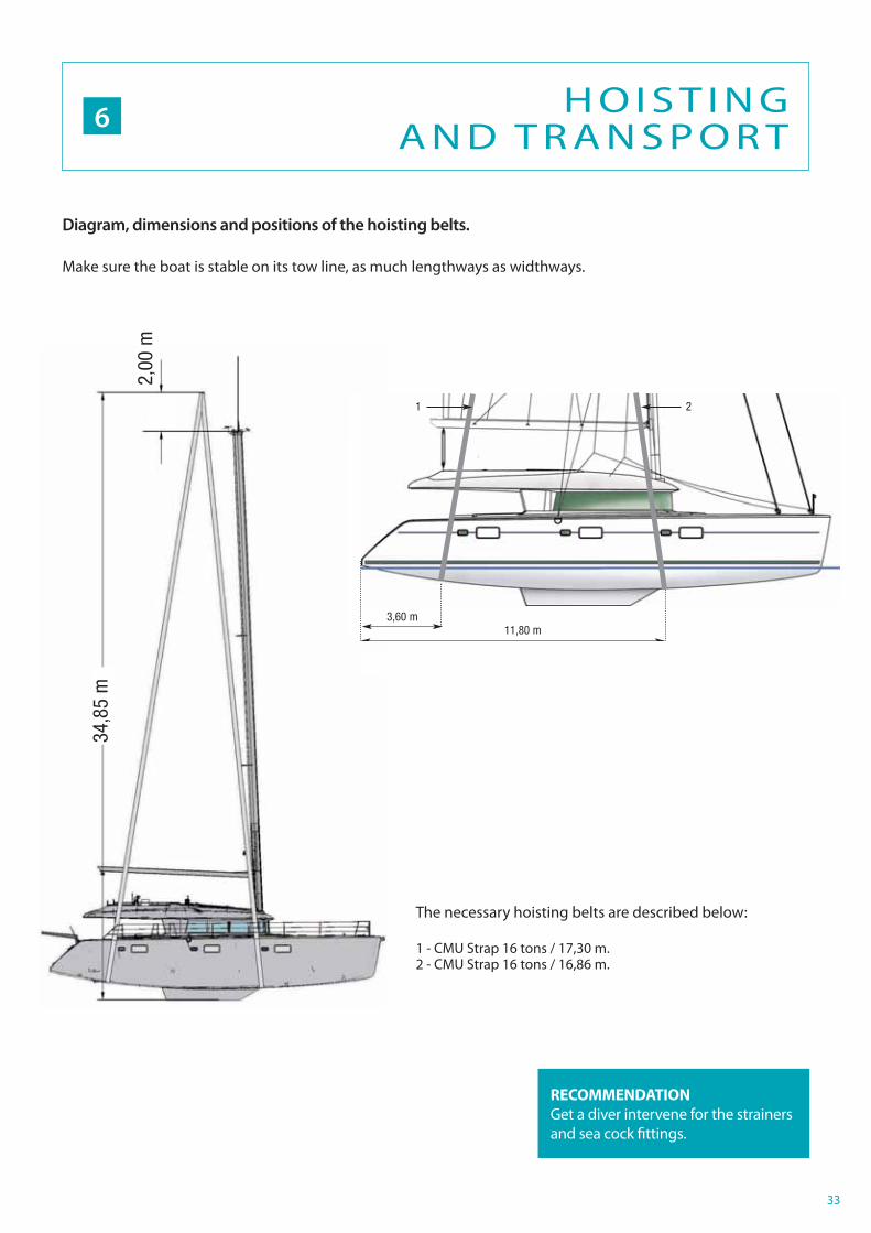
The necessary hoisting belts are described below:
1 - CMU Strap 16 tons / 17,30 m.2 - CMU Strap 16 tons / 16,86 m.
34,8
5 m
2,00
m
11,80 m3,60 m
1 2
6H O I S T I N G
A N D T R A N S P O R T
Diagram, dimensions and positions of the hoisting belts.
Make sure the boat is stable on its tow line, as much lengthways as widthways.
RECOMMENDATION
Get a diver intervene for the strainers and sea cock fi ttings.

34
ISOFDIS 8099 Art.12EN / NF - ISO 9094 - 2 annex BEN / NF - ISO 14895 annex BEN / NF - ISO 15083 annex A
R E F E R E N C E S A N D S TA N DA R D S7

35

162, quai de BrazzaCS 8121733072 Bordeaux Cedex - FranceTél.33 + (0) 557 80 92 80E-mail : [email protected]
www.cata-lagoon.com