owner’s m a n ua l and o p e r at i n g i n s t ru c t i o n s · pdf fileowner’s...
TRANSCRIPT

OWNER’S M A N UA L
AND O P E R AT I N G
I N S T RU C T I O N S
ProudlyManufactured in the U.S.A. by
Pyro Industries, Inc. Burlington, WA 98233

Congratulations on the purchase of your Whitfield Quest Pellet Stove!
When you purchased your Whitfield stove, you joined the ranks of thousands of concernedindividuals whose answer to their home heating system reflects their concern for aesthetics,efficiency and our environment.
We extend our continued support to help you achieve the maximum benefit and enjoymentavailable from your pellet stove.
This manual covers, in detail, the steps required to assemble and install your Whitfield pelletstove safely. Please familiarize yourself with this Owner's Manual before installing yourWhitfield stove.
We at Pyro Industries, Inc., manufacturer of the “Original Pellet Stove”, thank you forselecting a Whitfield as the answer to your home heating needs.
Sincerely,
All of us at Pyro Industries, Inc.
NOTE TO THE INSTALLER:Do not throw these instructions away. These instructions
must be left with the homeowner.
NOTE TO THE STOVE OWNER:Please view the “Operation & Maintenance” video included with the stove.

Safety Information 1Safety Notice . . . . . . . . . . . . . . . . . . . . . . . . . . . . . . . . . . . . . . . . . . . . . . . . 1
Stove Safety Label . . . . . . . . . . . . . . . . . . . . . . . . . . . . . . . . . . . . . . . . . . . . 1
Safety Precautions . . . . . . . . . . . . . . . . . . . . . . . . . . . . . . . . . . . . . . . . . . . . . 2
Safety Testing . . . . . . . . . . . . . . . . . . . . . . . . . . . . . . . . . . . . . . . . . . . . . . . 3
Automatic Safety Features . . . . . . . . . . . . . . . . . . . . . . . . . . . . . . . . . . . . . . . . 4
Power Outage . . . . . . . . . . . . . . . . . . 4
Overheating . . . . . . . . . . . . . . . . . . . 4
Safe Shut Down of Your Stove . . . . . . . . 4
Pellet Fuel Information 5General Information . . . . . . . . . . . . . . . . . . . . . . . . . . . . . . . . . . . . . . . . . . . 5
Clinkering . . . . . . . . . . . . . . . . . . . . . . . . . . . . . . . . . . . . . . . . . . . . . . . . . 5
Ash . . . . . . . . . . . . . . . . . . . . . . . . . . . . . . . . . . . . . . . . . . . . . . . . . . . . . 5
Fuel Feed Rates . . . . . . . . . . . . . . . . . . . . . . . . . . . . . . . . . . . . . . . . . . . . . . 6
Stove Operation 7Control Board Features . . . . . . . . . . . . . . . . . . . . . . . . . . . . . . . . . . . . . . . . . 7
Pre-Lighting Instructions . . . . . . . . . . . . . . . . . . . . . . . . . . . . . . . . . . . . . . . . 8
Lighting Stove With Optional FASTFIRE™ Self-lgniter . . . . . . . . . . . . . . . . . . . . . 8
Lighting Stove Without Optional FASTFIRE™ Self-lgniter . . . . . . . . . . . . . . . . . . . 9
Turning Off the Stove . . . . . . . . . . . . . . . . . . . . . . . . . . . . . . . . . . . . . . . . . . 9
General Operating information . . . . . . . . . . . . . . . . . . . . . . . . . . . . . . . . . . . . 10
Proper Burn Characteristics . . . . . . . . 10
Pellet Feed/Pellet Size . . . . . . . . . . . . 10
Long Burn Time . . . . . . . . . . . . . . . 10
Routine Cleaning & Maintenance 11Burn Grate ("UltraGrate") . . . . . . . . . . . . . . . . . . . . . . . . . . . . . . . . . . . . . . . 12
Heat Exchanger Tubes . . . . . . . . . . . . . . . . . . . . . . . . . . . . . . . . . . . . . . . . . 12
Heat Exchanger Baffle . . . . . . . . . . . . . . . . . . . . . . . . . . . . . . . . . . . . . . . . . 12
Ash Pan(s) . . . . . . . . . . . . . . . . . . . . . . . . . . . . . . . . . . . . . . . . . . . . . . . . 13
Freestanding model . . . . . . . . . . . . . 13
Insert model . . . . . . . . . . . . . . . . . 13
Exhaust Ducts . . . . . . . . . . . . . . . . . . . . . . . . . . . . . . . . . . . . . . . . . . . . . . 14
Rope Gasket . . . . . . . . . . . . . . . . . . . . . . . . . . . . . . . . . . . . . . . . . . . . . . . 15
Fan Motors Combustion and Convection . . . . . . . . . . . . . . . . . . . . . . . . . . . . . . 15
Table Of Contents

Stove & Hearth Preparation 16Stove Preparation . . . . . . . . . . . . . . . . . . . . . . . . . . . . . . . . . . . . . . . . . . . . 16
Freestanding Model . . . . . . . . . . . . . 16
Insert Model . . . . . . . . . . . . . . . . . 17
Floor Protection . . . . . . . . . . . . . . . . . . . . . . . . . . . . . . . . . . . . . . . . . . . . 17
Clearances to Combustibles . . . . . . . . . . . . . . . . . . . . . . . . . . . . . . . . . . . . . 18
Installation Guidelines 19Installation Disclaimer . . . . . . . . . . . . . . . . . . . . . . . . . . . . . . . . . . . . . . . . . 19
Stove Installation Check List . . . . . . . . . . . . . . . . . . . . . . . . . . . . . . . . . . . . . 19
Determining Equivalent Pipe Length . . . . . . . . . . . . . . . . . . . . . . . . . . . . . . . . 20
Venting Requirements 21Freestanding Stove Venting . . . . . . . . . . . . . . . . . . . . . . . . . . . . . . . . . . . . . . 21
Insert Stove Venting . . . . . . . . . . . . . . . . . . . . . . . . . . . . . . . . . . . . . . . . . 22-24
Typical Installations - Freestanding Stove 25Standard Horizontal Exhaust . . . . . . . . . . . . . . . . . . . . . . . . . . . . . . . . . . . 25-26
Vented Into Masonry Chimney . . . . . . . . . . . . . . . . . . . . . . . . . . . . . . . . . . . . 27
Vertically Vented Through Ceiling & Roof . . . . . . . . . . . . . . . . . . . . . . . . . . . . . 28
Vented Through Exterior Wall & Up-Through Roof . . . . . . . . . . . . . . . . . . . . . . . . 29
Connected to Metal (Class 'A') Chimney . . . . . . . . . . . . . . . . . . . . . . . . . . . . . . 30
Mobile Home Installation . . . . . . . . . . . . . . . . . . . . . . . . . . . . . . . . . . . . . . . 31
Typical installation Insert Stove 32Vented Into Existing Chimney . . . . . . . . . . . . . . . . . . . . . . . . . . . . . . . . . . . . 32
Trouble-Shooting Guide 33 -36
Optional Accessories 37
Warranty 38 -39
Table Of Contents (Cont.)
PLEASE NOTE:The drawings in this manual are not drawn to architectural scale and should beused for reference only. Actual dimensions as printed in the text, pictures and
drawings of this manual are accurate. Refer to this manual for detailed installationdimensions, instructions, specifications and other requirements.

SAFETY NOTICEThis stove must be installed and operated properly in order to prevent the possibility of a housefire. Please read this entire Owner's Manual BEFORE installing and using your Whitfieldpellet stove. Failure to follow these instructions could result in property damage, bodilyinjury or even death. Contact your local building or fire officials to obtain a permit and information on any installation restrictions and inspection requirements in your area.
STOVE SAFETY LABELA copy of the safety label for a Quest pellet stove is shown in Figure 1 below. The safety labelis located on the underside of the hopper lid on all Quest stoves. This label contains importantinformation about the installation and operation of your stove. In addition, your stove's serialnumber is located on this label (preceded by "WH-Q"). This manual is provided as a supple-ment to the information on the safety label. Please read the safety label carefully.
(Figure 1) Quest Safety Label
Safety Information
1
SAFETY PRECAUTIONS
Fuel - With advanced UltraGrate technology, the Whitfield Quest is designed and approved forthe burning of wood residue pellets with up to 3% ash content. The burning of agriculturalresidues (such as corn and alfalfa), waste paper, or cardboard in pellet form is not permitted.Failure to comply with this restriction will void all warranties and the safety listing of the stove.Confer with your dealer for more information on approved pellet fuels.
Continuous Operation - When operated correctly, the Whitfield Quest cannot be over-fired.Continuous operation at a maximum burn can, however, shorten the life of the electrical com-ponents (fans, auger motor, and electronic controls) and is not recommended.
Liquid Flammables - Gasoline or other flammable liquids must never be used to start or"freshen up" the fire. Keep all such liquids well away from the stove at all times.
Ashes - Any ashes removed from the Whitfield Quest must be deposited in a metal containerwith a tight-fitting lid. The closed container of ashes should be placed on a non-combustiblesurface or on the ground, well away from all combustible materials, pending final disposal. Ifthe ashes are disposed of by burial in soil or otherwise locally dispersed, they should beretained in the closed container until all cinders have thoroughly cooled.
Power - The appliance is provided with a grounded electrical cord. This cord should be con-nected to a standard, 115 volt, 60 Hz grounded electrical outlet. The approximate continuouspower requirement is 200 Watts. The power supply cord must be routed to avoid contact withany of the hot or sharp exterior surface areas of the stove. The stove will not operate without apower source for the fans and fuel feed system.
Auger - Pellet fuel is fed to the burn grate by an auger. This auger is driven by a high torquemotor. The auger is capable of doing serious harm to fingers. Keep pellets in the hopper at alltimes and keep fingers away from the auger. The auger can start and stop automatically at anytime while the stove is running.
Soot Formation - Burning with insufficient combustion air will result in the formation of soot.This soot may be deposited on the windows, in the flue, and in the heat exchangers. If theappliance has been vented through the wall and terminated, this soot may stain the outside ofthe house. This is a hazardous situation, in addition to being an inefficient use of pellet fuel.Check your stove frequently, and adjust combustion air as required.
Cleaning - There will be some build-up of dust and smaller quantities of soot or creosote in theexhaust system over the burn season. This will vary due to the ash content of the fuel beingburned. Conduct frequent inspections, initially, to determine appropriate cleaning intervals.
Safety Information (cont.)
2

SAFETY PRECAUTIONS-continued
Smoke Detector - Depending on your local codes, a smoke detector may be required in theroom where the stove is installed. We recommend that smoke detectors be installed in all homes and maintained in an operational condition at all times, no matter whether you are using a heating appliance or not.
Exhaust Pipe - The appliance is provided with an exhaust connector for a listed 3-inch, type "L", double-wall pellet vent pipe with a stainless steel inner liner. Single wall, stainless steel pipe (rigid or flexible) is acceptable for insert installations.
Mobile Home Installation - Any Whitfield Quest stove installed in a mobile home must beconnected to a source of outside air, electrically grounded to the steel chassis, and bolted to thefloor (unless otherwise specified by state or local authorities) to meet H.U.D. requirements.
SAFETY TESTINGWhitfield Pellet Stoves and Fireplace Inserts are safety tested and listed by Warnock HerseyProfessional Services, Ltd., an accredited testing laboratory. Tests were conducted in accordancewith the specifications and procedures listed in ASTM E-1509 for Pellet Heaters and UL 1482for solid fuel room heaters, as well as CSA and ULC standards. UL 1482 states requirements forinstallation as a Freestanding room heater, or hearth insert for masonry or metal (zero clearance)fireplaces. This appliance is designed specifically for use with approved pelletized fuels. It istested and listed for residential installation, according to current national and local buildingcodes, as either:
• Freestanding Room Heater
• A Hearth Insert (when installed into a masonry or factory built fireplace)
• A Mobile Home Heater
Safety Information (cont.)
3
PLEASE NOTE:This stove is not intended for use in commercial installations, other than
the dealership where the stove is being sold, without prior writtenapproval from Pyro Industries, Inc.

AUTOMATIC SAFETY FEATURES
Power Outage - During a power outage, the stove will shut down safely. It will not automaticallyrestart when the power is restored. However, a momentary power interruption may not shut yourstove down. A small amount of smoke will likely leak from the top of the window glass, the hopper and from the combustion air intake, if the stove is vented horizontally. This will not persist for more than 3 to 5 minutes and will not be a safety hazard. Your smoke alarm could beactivated.
To re-light the stove, follow the normal procedure for starting your stove.
Overheating - A high temperature switch will automatically shut down the stove if it overheats.The stove will need to be manually re-lit. Allow up to 45 minutes cooling time before re-lighting.If the overheating continues, contact your dealer for more information.
Safe Shut Down - While the stove is operating press the auger ''on'' button on the controlboard to turn the fuel feed off. Pellets will stop feeding and the red auger "on" light will stopblinking. Both fans will continue to operate. The fans will automatically turn off after 15 to 40minutes. The low temperature switch will also shut the stove down safely if it runs out of fuel.
Safety Information (cont.)
4
IMPORTANT: If the area in which you live is prone to frequent power outages,it is recommended that a minimum of 8 feet (2.5 m) of vertical vent pipe beincluded in a freestanding installation. In the event of a power failure, this willcreate a natural draft and minimize any spillage of exhaust gases into the room.

GENERAL INFORMATION
The Whitfield Quest, with its UltraGrate burn system, has been designed to burn wood residuepellets with up to 3% ash content. Only Pellet Fuel Institute (P.F.I.) approved fuels should beused in this stove. Wood Pellets manufactured to the P.F.I. Certification Standards are availablein two grades: STANDARD and PREMIUM. The premium grade pellets have a lower ash con-tent than the standard grade. The P.F.I. specification for standard and premium grade residentialpellet fuel follows:
CHLORIDES (Salt): Less than 300 p.p.m.BULK DENSITY: 40 lb./ cu. ft. minimumMOISTURE CONTENT: 8% maximumASH CONTENT: 3% maximum(Standard Grade)
1% maximum (Premium Grade)FINES: 0.5% maximum through a 1/8” screen
CLINKERINGSilica (or sand) in the fuel, along with other impurities, can cause clinkering. A clinker is a hardmass of silica formed in the burning process. Clinkering is a function of the fuel (not the stove),and adversely affects the performance of the stove by blocking off the air passages in the grate.Even a P.F.I. approved pellet fuel may tend to clinker. A clinker can be removed from the burngrate and placed in the ash pan with the use of the grate scraper/ash pan tool furnished withyour stove. See Routine Cleaning & Maintenance for more information.
ASHThe frequency of ash removal and other maintenance performed on the stove is directly propor-tional to the ash content of the fuel and how frequently you use your Whitfield stove. Low ashfuel may allow longer intervals between cleaning, however, a stove burning high ash fuel mayneed to be cleaned everyday.
PLEASE NOTE: Pyro Industries, Inc., has no control over the manufacturing of pellet fuel andwill not be held responsible for poor stove performance or any damage caused by inferior pelletfuels.
Pellet Fuel Information
5

FUEL FEED RATES
Different brands of pellets will feed at varying rates due to their size (length and diameter), anddensity. This may require a slight adjustment in the damper control or the pellet feed control tocompensate (see Stove Operation which begins on page 7).
CAUTION: This product is not designed to burn agricultural pellets (such ascorn and alfalfa) or pelletized fuels from waste paper, cardboard, etc. The useof unapproved, dirty, wet and/or high salt content fuel will void the stove'swarranty!
Contact your authorized Whitfield dealer for more information, if needed.
Pellet Fuel Information (cont.)
6

CONTROL BOARD FEATURES
"Start" Button - The push-button "Start" buttonactivates the convection fan and the combustion (exhaust) fan. If theexhaust does not reach proper operating temperature within 30 min-utes, the stove will automatically shut down. The fans can be restartedby pushing the "Start" button again after the 30 minute cycle.
"Auger On" Button - The push-button "Auger On"button activates the fuel feed (auger) motor only. The start buttonmust be activated first to send power to the auger "on" button. If theauger "on" button is pushed again, the fuel feed will stop and the fanswill continue to operate until the stove has cooled down sufficiently(this may take up to 45 minutes); then both of the fans will automatically turn off.
"Auger On" Light - The red "Auger On" light (L.E.D.) on the control panel indicates when there is power to the auger motor.When the auger motor is activated, this light will blink as the augermotor cycles on and off.
"Pellet Feed" Knob - The "Pellet Feed" knob allows you adjust theheat output of your stove by controlling the rate at which pellets arefed to the burn grate. Turning this knob counter clockwise lowers thefuel feed rate; turning the knob clockwise increases the fuel feed rate.
"Damper Control" Knob - This knob allows you to adjust thedamper, which controls the amount of combustion air that reaches theburn grate. For an efficient flame, the damper control knob should beadjusted whenever the "Pellet Feed" knob setting (fuel feed rate) is changed. This knob islocated on the upper third of the control board (see Figure2). When the damper has been cor-rectly adjusted, you will observe a brisk, yellow-to-whitish flame (refer to video for properflame appearance).
NOTE: The proper air settings will vary from stove to stove due to installation altitude, andthe fuel being burned. The LOW, MEDIUM, and HIGH marks should be used only as aguide for matching pellet feed settings to damper settings. Choose a setting that does notallow fuel to "pile up" in the grate. Adjust damper to get an active, bright yellow-white flame.
"Fan High/Low" Button - The "Fan High/Low" button sets the speed of the convection fanmotor to either a high or low setting. Choose the high setting to extract the most heat from yourstove; choose the low setting when feeding pellets at lower rates.
Stove Operation
7
(Figure 2) Stove Control Board

PRELIGHTING INSTRUCTIONS
When lighting your Whitfield stove for the first time, the auger feed tube must be "primed"(filled with pellets). Also, if the stove ever runs completely out of fuel, the auger system willneed to be primed again. To prime the auger feed tube:1. Fill the hopper with an approved pellet fuel and plug the stove into the wall outlet.
2. Press the "START" button on the control panel to activate both fans. Push the "Auger On"button on the control panel (this starts the auger motor). Next, turn the "Pellet Feed" knob to"HIGH" (the maximum feed rate).
3. Look through the stove’s window. The auger is fully primed when you can see the first pellets dropping into the grate. This will take 10 to 15 minutes.
4. Once the auger is primed, unplug the powercord and wait for a minimum of 30 seconds toturn off the fans and auger. [Note: This step is followed only when priming the auger and willnot need to be performed every time you start the stove, if fuel is in the hopper.] Once the stovehas shut down, plug the powercord back into the wall outlet.
LIGHTING STOVE WITH THE OPTIONAL FASTFIRE™ SELF-IGNITER
If you have purchased the optional FASTFIRE™ Self-Igniter from your dealer, you will need toperform the following start-up procedure:
1. Make sure the auger is primed (see Pre-Lighting Instructions above), then simply push the"START" button on the control board to activate the igniter.
2. Set the "Damper Control" knob in the "MEDIUM" range to obtain: proper air flow forcombustion.
3. Set the "Pellet Feed" control knob to the desired position.
4. Push the "Auger On" button to supply power to the auger motor. Pellets will start feedingintothe grate and should begin to ignite within three to seven minutes. The self-igniter will automat-ically shut off after 15 minutes.
5. It may be necessary to adjust the damper control knob after pellets have ignited and the stovehas had a few minutes to warm up.
Stove Operation (cont.)
8

LIGHTING STOVE WITHOUT THE OPTIONAL FASTFIRE™ SELF-IGNITER
1. If lighting your stove for first time, first follow Pre-lighting Instructions on page 8. Place arecommended fire starter (see your dealer for an appropriate fire starter) in the burn grate andput a handful of pellets on top of the starter (if using a gel starter, put the pellets in the gratefirst).
WARNING: DO NOT USE FLAMMABLE LIQUIDS TO START YOUR STOVE.WARNING: DO NOT OPERATE STOVE WITHOUT BURN GRATE IN PLACE
2. Light the fire starter in the burn grate with a match, and close the door. Turn the pellet feedknob to the "MEDIUM" setting.
3. Turn the "Damper Control" knob to the "MEDIUM" setting .
4. After approximately 10 seconds, press the "Start" button. You will notice that the fire willbecome active, and air will flow out of the heat exchanger tubes.
5. Once the pellets in the grate are burning sufficiently (red hot coals), press the "Auger On"button to activate the auger motor. If the auger is "primed" (see Pre-Lighting Instructions on page 8), pellets will now begin to feed into the burn grate.
6. After the fire is burning well, adjust the "Pellet Feed" knob to the desired setting. The red "Auger On" light will blink on and off. Adjust the damper control knob into the same range asthe pellet feed knob, or as necessary for proper combustion. Look for an active, bright yellow-white flame.
7. Push the "Fan High/Low" button to set the convection fan to the “HIGH” (or “LOW”) set-ting. Each time the button is pushed, the convection fan speed switches to the alternate setting.The stove can be safely operated at either the “HIGH” or “LOW” convection air setting for anyfuel feed rate.
TURNING OFF THE STOVE
To turn off the stove, simply push the "Auger On" button once, which will turn off the augermotor, and stop the fuel feed. Both fans will run until the stove has cooled down sufficiently.At this point, a low-limit snap switch will activate to automatically shut off the stove.
Stove Operation (cont.)
9

GENERAL OPERATING INFORMATION
Proper Burn Characteristics - The flame in your stove should be bright yellow during normaloperation. If the flame becomes lazy with a reddish/orange color, the damper control knob willneed to be turned clockwise (set higher) to provide more combustion air.
Excessive amounts of fly-ash built up in the grate, clinkers in the grate, or leakage of air (if thegrate is not properly seated) will starve the fire for air and pellets will pile up in the grate.Follow the grate cleaning procedure outlined in the Routine Cleaning & Maintenance section.If the grate blockage problem persists review the trouble-shooting section at the end of thismanual.
NOTE: If the flame is smoky red/orange with evidence of soot at the top of the flame, yourstove needs more combustion air; adjust the damper until the flame begins to ‘dance’. If theflame is 'short' at the higher burn rates or if the pellets are burning up in the grate beforenew pellets are fed into the fire, adjust the damper for slightly less combustion air. Thedamper position will probably need to be changed whenever the pellet feed setting is changed.The damper setting should be increased slightly when switching from a premium grade pelletto a standard grade or other higher ash pellet.
Pellet Feed/ Pellet Size - The pellet feed system is designed to handle a wide range of pelletsizes up to a maximum of 5/16" diameter. You may notice a difference in the burn if youchange pellet fuel sizes. Different pellets may feed at considerably different rates. The longerthe pellet, the slower it will feed and vice versa.
If the stove will not stay burning at the minimum fuel feed setting, that pellet type may not befeeding fast enough. If this happens, reduce the amount of combustion air using the "DamperControl" knob, or increase the fuel feed rate by using the "Fuel Feed" knob .
Long Burn Time - The stove may be safely operated on a continuous basis. A 40 pound bag ofpellets should last approximately 12 hours on the "HIGH" fuel feed setting and up to 40 hourson "LOW," depending on the pellet fuel burned.
Ash Release Slide Plates - See boxed statement below:
Stove Operation (cont.)
10
IMPORTANT: When operating the freestanding stove, it is important to makesure that the ash release slide plates are completely closed. Air leakagearound even partially open plates will negatively affect the stove's performanceand may cause pellets to pile up in the grate.
ROUTINE CLEANING & MAINTENANCE
The following areas need to be routinely inspected for ash build-up, and cleaned when necessary:
1 Burn Grate (“UltraGrate™”)
2 Heat Exchanger Tubes
3 Heat Exchanger Baffle
4 Ash Pan(s)
5 Exhaust Vent
6 Rope Gasket (around door, ash pan, and window areas)
7 Fan Motors - Combustion and Convection
The amount of ash build-up in your stove is directly proportional to the ash content of the fuelyou are burning (see Pellet Fuel Information, page 5). After a period of time (a week, or so)inspect the burn grate and heat exchanger tubes, heat exchanger baffle, ash pan and exhaustvent areas. Set an appropriate maintenance schedule for each area based on the amount of ashyou find. Your stove’s performance will be affected if enough ash accumulates to restrict airflow in any area. These items should also be checked periodically, and may require cleaningand/or maintenance:
The seven topics listed above are discussed in more detail on the following pages. In addition,windows and plated accessories may be cleaned, once cool, using a soft cloth and an appro-priate commercial all-purpose cleaner suitable for glass. Do not use products that may leave aflammable residue.
Routine Cleaning & Maintenance
11
NOTE: The stove will need to be shut off and cooled down before routinecleaning is performed. ALWAYS DISCONNECT POWER before doing anyroutine cleaning or repair work on the stove.

BURN GRATE
The burn grate should be inspected periodical-ly to ensure that the airflow has not becomeblocked with ash or clinkers. The burn gratecan easily be cleaned with the gratescraper/ash pan tool (see Figure 3), or it can beremoved for more extensive cleaning. Whenburning "Standard" grade pellets, it will benecessary to clean the ash pan more often thanwhen burning "premium" grade pellets. Onthe insert model, it is very important to moni-tor the ash build-up under the burn grate, toprevent restriction of combustion air flowthrough the burn grate. Check the center ashpan regularly. Empty before the ash builds upto the bottom of the grate.
HEAT EXCHANGER TUBES
A rod located above the convection air louvers is used for cleaning the heat exchanger tubes. Besure the door is closed while you are scraping these tubes. By pulling this rod up and down afew times, you will clean the fly ash off the heat exchanger tubes (see Figure 4). A hole is provided in the handle of your grate scraper tool for pulling this rod.NOTE: If your stove was recently turned off, the rod will still be hot.
Routine Cleaning & Maintenance (cont.)
12
(Figure 3) - Cleaning Burn Grate
(Figure 4) Cleaning Heat Exchanger Tubes (Figure 5) Heat Exchanger Baffle Installed
HeatExchangerBaffle
TubeScraperRod

ASH PAN(S)
Freestanding Model - The ash pan will have to be emptied periodically. The ash pan on thefree-standing model is located in the pedestal tower. It can be removed by turning the T-Barlatch fully counter-clockwise. Then pull ash pan away from stove. Ash that accumulates aroundthe grate can be “dropped” into the ash pan without opening the firebox door. Simply pull openthe ash release slide plates (show in Figures 6 and 7) using the grate scraper tool provided.Remove the ash pan as shown in (Figure 8). NOTE: Make sure to fully close the plates whenfinished. Failure to close the ash release slide plates completely may cause the fuel to burnpoorly (due to reduced air flow through the grate, which may then cause pellets to "pile up"in the grate.
Insert Model - There are two separate ash pans to empty on the insert model: (1) a small pandirectly beneath the burn grate, and (2) a larger pan that covers the left and right sides of thefirebox. Open the firebox door to access the ash pans. Scrape the accumulated ash into the ashpans using the grate scraper tool, pay special attention to the grate itself. Next, remove the center, smaller pan using the grate scraper tool (see Figure 9). Be sure to dump the ashes into anon-combustible container. Return the small ash pan to the stove. Repeat this procedure for thelarger ash pan (see Figure 10). Close the firebox door and latch it.
Note: Dispose of the ash in accordance with the instructions found on page 2 of this manual!
Routine Cleaning & Maintenance (cont.)
13
(Figure 6) - Locating AshRelease Slide Plates
(Figure 7) - Opening AshRelease Slide Plates
(Figure 8) - Emptying AshPan on Freestanding Stove
(Figure 9) - Emptying Small Ash Pan on Insert Stove
(Figure 10) - Emptying upper Ash Pan on Insert Stove
Ash SlidesIn Fully
Closed Position
Ash Slides Fully Open
Ash drops through these openings

EXHAUST DUCTS
Inspect the exhaust ducts periodically andclean when necessary. Fly ash will accu-mulate at all bends in the exhaust system.Based on this inspection, determine howoften, and to what extent, the exhaust sys-tem will need to be cleaned. Note: Largeamounts of fly ash build-up will restrictc o m bustion air fl ow and reduce thestove's efficiency.
On insert models, To access the clean outcup, open the right-hand shroud panel(when the stove is cold), and remove thetee clean-out cup (shown in Figure 11) toinspect the ash build-up in the exhaust system. Twist the clean-out cup to the leftto release it.
Routine Cleaning & Maintenance (cont.)
14
(Figure 11)Clean-Out Cup Connected to Tee

ROPE GASKET
The rope gasket should be checked periodically and replaced or repaired if necessary. This gas-ket is located around the firebox door and windows (plus the ash pan on freestanding models).
A one-inch strip of paper may be used to test the integrity of the door seal. Close the door onthe paper in several different locations and pull. A slight amount of friction is normal. The doorgasket does not need to be "tight" in all areas, since a small amount of air drawn into the stovearound the gasket is not hazardous or detrimental to the stove's performance.
FAN MOTORS: COMBUSTION AND CONVECTION
The two fan motors require lubrication annually with not more than two drops of a high quali-ty, non-detergent oil (your dealer can make a recommendation) at the lubrication points shownbelow. Do not over-oil the motors! Too much oil can shorten motor life.
The combustion fan, (exhaust Fan) located on the right side of the stove, has two black rubberplugs that must be removed. To access the exhaust fan, the right side panel may be opened byremoving the top screw (between the louvers) and popping open the "bulb" latch at the bottom.
To gain access to the convection fan, open the left side panel (follow the above procedure foropening the right side panel ). On the convection fan, the oiling ports are the “half-moon” open-ings in the motor housing.
Note: The orientation of the motors may vary from fan to fan. The oiling ports, therefore,may not be in exactly the same location as shown in these photos.
Routine Cleaning & Maintenance (cont.)
15
(Figure 13) - Convection Fan Oiling Ports (Failure 14) - Combustion Fan Oiling Ports
Oil Port
Oil Port
Oil Port(Plugs in Place)

STOVE PREPARATION
Remove any external packaging from the stove. Lift the hopper lid and remove any pre-pack-aged items that were shipped in the hopper. Also open the firebox door and remove any pre-packaged items. Use a 7/16" socket or open end wrench, to remove the two bolts that secure the stove to the wood shipping pallet (see Figure 16)
Freestanding Model:
1. Remove the pedestal from its box and place it beside the stove.
2. With a helper, lift the stove onto its pedestal base. The stud on the front of the stove must fitinto the front mounting hole on the pedestal.
3. Place one 1/4" nut over the front stud and two 1/4" bolts into the two holes at the rear, wherethe stove was originally secured to the pallet (see Figure 17).
4. The rear panel of the pedestal must be secured to the bottom plate of the stove with the othertwo 1/4" bolts.
5. Tighten all five fasteners with a properly sized wrench or socket.
NOTE: Ensure that the stove sits evenly on the pedestal. Excessive air leakage will causepoor stove performance.
Stove & Hearth Preparation
16
Remove the two 1/4" bolts from theunderside of the pallet
BOTTOM VIEW OF PALLET
Attach stove to the pedestal using one1/4" nut in the front, two 1/4" boltsin the back corners and two in the
rear panel (not shown)
TOP VIEW OF STOVE PEDESTAL
(Figure 16) Removing Pallet Bolts (Figure 17) Pedestal Mounting

STOVE PREPARATION continued
Insert Model:1. Refer to the shroud installation instructions included in the
shroud box.2. Installing the control board- the damper adjustment is
controlled by a cable mechanism. On insert stoves, the control board assembly (see Figures 2 and 18) will need to be removed from the side of the stove and attached to the back of the shroud side panel. After attaching the left side shroud panel to the stove, follow this procedure:
a) Remove the four lock-nuts from the back of the shroud left panel and set them close by.
b) Use a 1/4" nut driver or socket to remove the two screws that hold the control board assembly to the bottom side of the stove. Without turning the control board assembly, slip it over the four studs on the back of the left side panel (see Figure 18).
c) Place the four lock-nuts back on the studs, and tighten them with a 3/8" socket or nut driver.
d) With the damper control knob set to the lowest position of the “LOW” Range (damper fully closed), look under the auger tube, and verify that the cable is still hooked into the damper control arm. Turn the Damper Control knob through its full range to check for proper function.
FLOOR PROTECTION
Your Whitfield pellet stove must be installedon a non-combustible protective floor pad(3/8" minimum thickness material), or on amasonry hearth. The hearth or floor padmust extend a minimum of 6" from the frontand both sides of the stove (as shown inFigure 19), or to the nearest permitted corm-bustible material if less than 6".
Stove & Hearth Preparation (cont.)
17
(Figure 19) Floor Protection Requirements
(Figure 18) Control board on Shroud Panel
Non-combustibleFloor protector
TOP VIEW OF STOVE ON FLOOR PADFloor protector must extend at least 6"from the front and sides of the stove.
6”
6”
6”

CLEARANCES TO COMBUSTIBLES
Figure 20 shows the minimum clearances to combustible materials that must be maintained.Keep all combustibles at least 18" away (measured horizontally) from the glass windows.Maximum alcove depth allowed is 24", minimum alcove height allowed is 47-1/2".
Stove & Hearth Preparation (cont.)
18
(Figure 20) - Clearances to Combustible Materials
Min. 1”
Min. 1”
Min. 1”
Min. 4”
Min. 18”
Min. 4”Min. 4”
Max. 24”

Your Whitfield Quest may be installed as:• A freestanding stove with a pedestal placed on a non-combustible floor pad.• A mobile home heater placed on a non-combustible floor pad, provided with a source of outside air, bolted down and electrically grounded to the chassis of the home (see page 31) .• A fireplace insert set into a masonry or factory built fireplace.
INSTALLATION DISCLAIMER
This stove's exhaust system works with negative combustion chamber pressure and a slightlypositive chimney pressure. Therefore, it is imperative that the exhaust system be gas-tight andinstalled correctly. Since Pyro Industries, Inc., has no control over the installation of your stove,Pyro Industries grants no warranty, implied or stated, for the installation or maintenance of yourstove, and assumes no responsibility for any consequential damage(s).It is strongly recommended that you have an Authorized Whitfield Dealer install your stove.If you install the stove yourself, you should review your installation plan with the AuthorizedWhitfield Dealership that sold you the stove.
STOVE INSTALLATION CHECKLIST
The following check list should be used when your Quest stove is installed. Check off eachitem as it is completed.
❑ If you haven't done so already, read the Stove & Hearth Preparation section, and follow the instructions outlined there.
❑ Determine the appropriate measurements and location for your installation.❑ Read this entire Installation Guidelines section.❑ Read the appropriate Venting Requirements sub-section: Insert or Freestanding.❑ Refer to either Typical Installations - Freestanding or Typical Installation - Insert Stove
(depending on your stove type) to find the appropriate installation.❑ Pre-fit all items before you install, fasten, cut holes or set up the stove permanently.❑ Prior to lighting your stove read the entire Safety Information Pellet Fuel Information,
andStove Operation sections.❑ Follow the Pre-Lighting Instructions outlined in the Stove Operation section.❑ Follow the appropriate lighting instructions section: see Lighting the Stove With (or
Without) FASTFIRE™ Self-Igniter (located on pages 8 and 9).❑ After you have begun operation of your stove, review the Routine Cleaning &
Maintenance section.
Enjoy the warmth from your new Whitfield Quest Pellet Stove!
Installation Guidelines
19

DETERMINING EQUIVALENT PIPE LENGTH
Installation Guidelines (cont.)
To determine whether a 3” or 4” exhaust system is required for your installation, review thesample installation below. Fill out the top chart, and calculate your total equivalent pipe length.After you have the total equivalent pipe length, use the chart at the bottom of the page to deter-mine if your installation requires 3” or 4” exhaust pipe.
Type of Pipe # of Elbows or Equivalent Feet Total Equivalent FeetFeet of pipe
90o Elbows/Tee(A &F) 2 x 5 ft. (1.5m) 10 (3m)
45o Elbows(C) 1 x 3 ft. (1m) 3 (1m)
Horizontal Pipe(B&E) 3 x 1 ft. (.3m) 3 (1m)
Vertical Pipe(D) 8 x .5 ft. (.15m) 4 (1.2m)
Sample Installation Chart
TOTAL: 20
A- 90 Deg. Elbow
B- 1’ Horizontal Pipe
C- 45 Degree Elbow
D- Standoff Braces
30
20
10
0 1 2 3 4 5 6 7 8 9 1 0
4 INCH DIAMETER ONLY
3 OR 4 INCH DIAMETER
Pipe Selection Chart
Type of Pipe # of Elbows or Feet of pipe Equivalent Feet Total Equivalent Feet
90o Elbows x 5(1.5m)
45o Elbows x 3(1m)
Horizontal Pipe x 1(.3m)
Vertical Pipe x 5(.15m)
Altitude in Thousands of Feet
20
A
E
F
H
G
B
C
D
(Figure 22)-Equivalent Length versus Altitude Chart
(Figure 21)-Sample Pipe Configuration
NOTE: For the example installationsabove, 4 inch diameter pipe would be usedfor installations at altitudes above 3,000feet; 3 or 4 inch pipe would be suitablebelow 3,000 feet.
E- 8’ Vertical Pipe
F- 2’ Horizontal Pipe
G- 90 Degree Tee
H- Wall Thimble

IMPORTANT: It is recommended that only an authorized dealer install yourpellet stove. The following installation guidelines must be followed to ensureconformity with both the safety listing of the stove and local building codes.
WARNING: Do not vent into a flue serving another appliance. Do not install adamper in the exhaust pipe.
CAUTION: On all direct vent installations (short, horizontal runs), care shouldbe taken when choosing a location for terminating the vent. It is not recom-mended to directly vent the exhaust pipe on the prevailing wind side of the house.
FREESTANDING STOVE VENTING
Venting Requirements
21
A listed 3 or 4 inch type "L" pellet vent exhaust system must be used for freestanding installa-tions and attached (and sealed) to the pipe connector provided on the back of the stove. Use a 3-to-4 inch adapter or a 3-to-4 inch "tee" in order to run 4 inch pipe. The vent termination mustbe located no less than 48" (1.2m) from any opening through which flue gases could re-enterthe building (such as windows and doors), not less than 24" (0.6m) from an adjacent building,and not less than 7' (2.2m) above grade when located near public walk-ways. The final termina-tion of the exhaust system must be configured so that flue gases do not jeopardize the safety ofpeople passing by, overheat combustible portions of nearby structures, or enter the building.Keep brush, plants and shrubs at least 36" (0.9m) away from the vent termination. Since sparksmay escape from the exhaust pipe of any stove, always use caution when positioning the ventpipe. NOTE: Refer to the pipe manufacturer's instructions when installing and terminat-ing the exhaust.
RIGHT SIDE VIEW
Dimensional Tolerance +/-1/4”Pipe Locations measured to Centerline
REAR VIEW
(Figure 23) Freestanding Stove Dimensions
21 3/8”
291/2”
111/2”
5 7/8”
3 1/2”
9”10”
21”

FREESTANDING STOVE VENTING continued
Ninety-degree elbows accumulate fly ash and soot, reducing the exhaust flow and lowering theperformance of the stove. Horizontal runs of pipe will collect fly ash as well. It is recommendedthat a single or double clean-out tee be installed at every 90 degree turn so that fly ash canaccumulate at the bottom of the tee. Total length of horizontal vent must not exceed 25 feet(7.7m; see Determining Equivalent Pipe Length on page 20).
If a 90 degree turn connects a vertical run of pipe to a horizontal run (as you follow the exhaustaway from the stove), a tee is not required. At any other 90 degree turn, installation of a clean-out tee is recommended to permit periodic cleaning of both the horizontal and vertical runs ofpipe.
INSERT STOVE VENTING
A 3" single-wall, stainless steel flexible or rigid exhaust pipe may be used for insert installa-tions in place of double-wall, type "L" vent. The pipe should be connected to the suppliedclean-out tee. High-temperature silicone sealant should be used at the vent pipe connections toensure a “gas-tight” seal.
When venting through an existing chimney (masonry or factory built) the chimney must becleaned. All creosote, dust and ash must be removed (see page 32 for more information onpreparing the fireplace for the insert installation).
The "L" vent or single wall stainless exhaust system must be installed so as to be gas-tight!The vent manufacturer's installation procedures must be followed. In addition, pipe connections,joints and all pipe seams within the home should be sealed with high-temperature, vulcanizedsilicone sealer (RTV).
If an insert is to be installed into an unlined masonry chimney, the 3" or 4" rigid or flex pipemust be extended to the top of the existing chimney. All insert installations must be linedto the top of the chimney (10 feet minimum length above the stove) with stainless flex pipeor a pellet vent system.
After the chimney has been lined to the top of the existing flue, any opening between the exist-ing chimney and the pipe/vent liner should be sealed with a metal plate. Use a clamp or otherfixture above the sealing plate to support the weight of the vent system.
Venting Requirements (cont.)
22

INSERT STOVE VENTING - continued
Venting Requirements (cont.)
23
(Figure 24)-Insert Pipe Adapter Connection
(Figure 25)-Front View of Insert
Contact your dealer for further assistance or information on installing your Whitfield Quest Insert.
DISCRIPTION W H
STD SHROUD ASSY 40 1/2” 28”
LRG SHROUD ASSY 44” 31”
H
W
21”
10”
21”
RemovableClean-outCup
Clean-out “tee”
“Tee” branch
Cast exhaust duct

INSERT STOVE VENTING - continued
Venting Requirements (cont.)
24
(Figure 26) Left Side View of Insert
(Figure 27) Back View of Insert
30 1/2”
15 1/2”
24 1/4”
20”
24 1/4”

STANDARD HORIZONTAL EXHAUST
1. Locate the proper position for the type "L" Wall Thimble (refer to Figure 28 for types ofpipes mentioned in this section). Avoid cutting wall studs when installing your pipe. Use a sabersaw or key hole saw to cut the proper diameter hole through the wall to accommodate the WallThimble. Use extreme caution to avoid cutting into power lines within the wall of the home. Thehole size will depend on the brand of pellet vent that you are using. Install the Wall Thimble inthe hole according to the pipe manufacturer's instructions. A standard horizontal installation isshown in (Figure 29).
2. Position the stove approximately 12" (0.3m) from the wall on the floor pad. Push type "L-vent" pipe through Wall Thimble. Squeeze a bead of RTV high-temperature silicone sealeraround the end of the machined portion of the 3" (76 mm) pipe connector on the back of thestove. Firmly push on a section of type "L-vent" pipe until the inner pipe liner pushes into theRTV bead.
3. Push the stove (with pipe attached) towards wall. The pipe will go through the Wall Thimble.Do not position the back of the stove closer than 1" (25 mm) from the wall. Note: 6 to 8 inchesof back clearance will provide easier access for servicing the stove, however, a larger hearthpad may be required.
4. Install type "L-vent" 45 degree elbow with rodent screen or cap (optional) on outside end ofpipe. The rodent screen should be no less than 1/2" (13 mm) mesh and may clog with soot andash if left unattended during the burn season. NOTE: The end of the exhaust pipe must extend aminimum of 12'' (0.3m) from the outside wall of the building.
5. If the installation requires a source of outside combustion air; cut a separate hole through thewall for the fresh air tube. This tube should be 1-5/8” (42mm) minimum diameter non-com-bustible pipe. Connect outside air pipe to air inlet on stove. This tube must be terminated with a90 degree elbow or hood. NOTE: Air may also be drawn from a crawl space under the home.
Typical Installations – Freestanding Stove
25
(Figure 28) - Horizontal Installation Components
ExhaustPort
QuickDisconnect
Straight “L-vent”Pipe
Inlet-AirPort
Metal FreshAir Pipe
LythermGasket
WallThimble
WallThimble
Holes throughthe Wall for the
Thimble &Fresh Air Pipe
45o DegreeElbow Jointfor Fresh Air Pipe
BACK SIDE OF STOVE

STANDARD HORIZONTAL EXHAUST - continued
Typical Installations – Freestanding Stove
26
(Figure 29) Standard Horizontal Installation
6” Minimum
Noncombustible floor protection
1” Min.
12” Min.
1” Minimumclearance from back of stove to combustible material
6” Minimumfrom front ofstove to edge ofnon-com-bustible floorprotection
Pipe mustextend aminimum of12 inchesfrom outsidewall.
IMPORTANT:We recommend at least2” to 3” min. between the stove and wall,to allow room for servicing, power cordand the hopper lid.

VENTED INTO MASONRY CHIMNEYA freestanding Quest may be vented into an existing flue. If a liner is run all the way to the topof the existing chimney, the top should be sealed with a metal plate (aluminum, or galvanizedorstainless steel). Start the vertical run with a "tee" at the back of the stove. Other options are
Typical Installations – Freestanding Stove (cont.)
27
(Figure 30) Freestanding Vented Into Masonry Chimney
1” Minimumclearance from back of stove to combustible material
6” Minimumfrom front ofstove to edge ofnon-com-bustible floorprotection
Option: Clean-out doorto access “tee”
OptionalComplete
Liner
All vertical piperuns shouldbegin with a 3” or 4”clean-out “tee”
6” Min.
IMPORTANT:We recommend at least2” to 3” min. between the stove and wall,to allow room for servicing, power cordand the hopper lid.

VERTICALLY VENTED THROUGH CEILING & ROOF
Typical Installations – Freestanding Stove (cont.)
28
(Figure 31) Vertically Vented Through Ceiling & Roof
VENT CAP
6” Min.
3” Min.
Use ceiling support orfirestop when ventingthrough a floor or ceiling
Maintain 3 inchminimum pipe clearance tocombustible surfaces.
IMPORTANT:We recommend at least2” to 3” min. between the stove and wall,to allow room for servicing, power cordand the hopper lid.
Follow the vent manufacturer'srecommendation for minimumtermination height above roof
STORM COLLAR
ROOF FLASHING
VERTICALLY VENTED THROUGH CEILING & ROOF
Typical Installations – Freestanding Stove cont.)
29
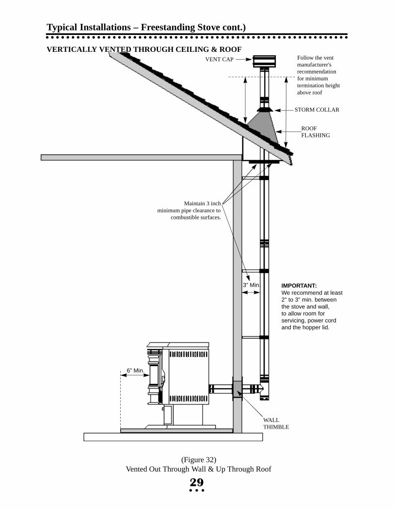
(Figure 32) Vented Out Through Wall & Up Through Roof
Maintain 3 inchminimum pipe clearance to
combustible surfaces.
Follow the vent manufacturer'srecommendation for minimumtermination height above roof
VENT CAP
STORM COLLAR
ROOF FLASHING
WALLTHIMBLE
6” Min.
3” Min. IMPORTANT:We recommend at least2” to 3” min. between the stove and wall,to allow room for servicing, power cordand the hopper lid.

VENTED OUT THROUGH EXTERIOR WALL & UP THROUGH ROOFCONNECTED TO A METAL (CLASS 'A') CHIMNEY
An existing metal (Class 'A') chimney (used for wood stoves) may be used to terminate a verti-cally vented stove. The pellet vent may be directly connected to the chimney or run all the way
Typical Installations – Freestanding Stove (cont.)
30
(Figure 33) Connected to a Class 'A' Chimney
Existingchimneyor “Class A”wood stovechimney
Pipe may passthrough existingchimney or beconnected to apipe reducer
It is not required to extend the“L-vent” pipe up through theexisting class “A” chimney.However, a “gas tight” sealmust be made at the transition point.
RAIN CAP
6” Min.
1” Min. IMPORTANT:We recommend at least2” to 3” min. between the stove and wall,to allow room for servicing, power cordand the hopper lid.

through. It is a good idea to extend the vertical pellet vent to the top of an oversized chimney.MOBILE HOME INSTALLATION
For mobile home installations, the following items are recommended and may be required (in addition to the standard installation instructions) by local, state or federal building codes:
• Stove must be permanently bolted to the floor
• Stove must have a permanent outside air source
• Stove must be permanently electrically grounded to the steel chassis of the home
CAUTION: The structural integrity of the manufactured home floor, wall andceiling/roof must be maintained.
Typical Installations – Freestanding Stove (cont.)
(Figure 34) Standard Mobile Home Installation
6” Min.
Noncombustiblefloor protection
Steel chassis of mobile home
Electrical ground to chassis
Bolt stove down
Outside air Intake and exhaustmust terminate a minimum of12” away from each otherFloor
1” Min.
12” Min.
1” Minimumclearance from back of stove to combustible material
6” Minimumfrom front ofstove to edge ofnon-com-bustible floorprotection
Pipe mustextend aminimum of12 inchesfrom outsidewall.
31
IMPORTANT:We recommend at least2” to 3” min. between the stove and wall,to allow room for servicing, power cordand the hopper lid.

Typical Installations – Insert Stove
32
8” Minimumclearance
6” Minimumclearance
Seal chimney top with steel plateand/or pipe support
RAIN CAP
OptionalmetalPlate
RemovableClean-outcup
Clean-out Tee
INSERT STOVE VENTED INTOEXISTING CHIMNEY
The Quest insert may be installed in a masonryor factory built fireplace as shown below. Wheninstalling into the existing chimney, the exhaustventing system should be extended to the top ofthe chimney as shown below. However, if thevent pipe cannot be run to the top of the chim-ney, the pipe must extend a minimum of 10feet (3m) above the exhaust connection on thestove and be sealed with a steel plate in thedamper area. Ensure that the end of any flexpipe used in this type of installation is notblocked, when terminated inside the existingflue. Note: Any installation that does not runall the way to the top of the chimney is notrecommended.
We also recommend that the fireplace cavity bethoroughly cleaned and sealed with latex paint ormasonry sealer. The paint will seal in old sootand creosote and help prevent fine dust frombeing pulled into the stove's convection fan andblown into the house.
IMPORTANT NOTE:Make sure the chimneyand fireplace are cleanand free of soot and ashesBEFORE installationbegins. Failure to do somay result in the transferof soot into the room.

Trouble Shooting
33
PROBLEM CAUSE(S) SOLUTIONS
Fire burns with a lazy orangeflame. Pellets build up in thegrate and soot forms on thewindow.
Fire goes out or stove shutsdown automatically
There is insufficient combustion air.
The hopper is empty
Pellets are not feeding.
The high limit temperatureswitch has tripped.
Remove any clinkers or ash from thebottom of the grate that might beobstructing the primary air passages(between the rods).
Change to a better grade of fuel ifnecessary.
Check that the damper has beenopened enough for the amount of fuel feed.
Check that the heat exchange tubesare not coated with ash.
Clean internal exhaust ducts.
Check gasket seal around the fireboxdoor (and ash pan areas on the free-standing stove). Use a thin strip ofpaper, 1 in. wide, open the door andclose it on the paper strip. A slightfriction should be felt when the paperstrip is pulled. Repeat this process atvarious locations around the door gasket. Replace the door gasket if necessary.
Check for blockage in the air inletduct or exhaust pipe. Clean as necessary; empty the ash pan.
Close ash slide plates.
Have your Whitfield dealer checkyour combustion blower.
Refill hopper.
See (Pellets will not feed) below.
Allow stove to cool for 1 hour and re-light. If the stove has been operatingat a medium to high burn rate and theconvection fan has been turned down“LOW” then the fan should be
WARNING: Unplug stove from wall outlet before performing service work!

Trouble Shooting (cont.)
34
PROBLEM CAUSE(S) SOLUTIONS
Fire goes out or stove shutsdown automatically
Pellets will not feed.
Stove runs for 30 minutesthen shuts down.
Fans will not shut off afterfuel has been switched off andthe stove has cooled down.
Fans will not operate whenthe start switch is depressed.
The high limit temperatureswitch has tripped.
There is too much combustionair for the amount of fuel.
The hopper is empty.
The auger motor or circuitboard may be defective. Thepressure switch tap or hose maybe blocked.
Auger jam
The exhaust gases are not up totemperature.
The low limit snap switch is notoperating correctly.
The wires to the low limit snapswitch are loose ordisconnected.
The low limit snap switch hasfailed in the closed position.
There is no power to the stove.
turned up higher. If this problem per-sists (particularly at lower burn rates)then the high-limit snap switch shouldbe replaced by your certified Whitfield dealer.
Adjust the damper to reduce combus-tion air flow.
Refill hopper.
Check to be sure that there is noblockage in the pressure tap or hose.Have your certified Whitfield dealerdiagnose the problem and clean orreplace any necessary parts.
Check hopper or feed tube for foreignobject. Gently rock the auger motorback and forth to release jammed pel-lets
Press start switch and re-light stove if necessary.
Have your certified Whitfield dealerreplace the low limit snap switch.
Check wires between the snap switchand the wiring harness. Make sure thatthere are good connections betweenthe wires and their terminals.
Have your certified Whitfield dealerreplace the low limit snap switch.
Check that the stove is plugged in tothe wall outlet.
Check to see if your circuit breakerhas tripped.

Trouble Shooting (cont.)
35
PROBLEM CAUSE(S) SOLUTIONS
Fans will not operate whenthe start switch is depressed.
There is soot or fly ash in thehouse.
With optional FASTFIRE™Self-Igniter, pellets do notignite within 15 minute timercycle; igniter probe glows red.
There is no power to the controlboard.
The window is being cleanedwhen the stove is operating.
There is leakage at the jointsbetween the combustion fan,exhaust pipe, and “L” vent. Thiswill be evidenced by dust on theimpeller of the convection fan,and inside the heat exchangertubes.
For a fireplace insert installation,if existing fireplace opening wasnot thoroughly cleaned andsealed (painted) before the insertwas installed, the convection fanmay be picking up dust, soot orash and blowing it into thehouse.
The stove is being cleaned withan unapproved vacuum.
No fuel supply.
Insufficient combustion air flow.
Check the connections between thehigh-limit snap switch and the harness. Call your Whitfield Dealerfor a diagnosis.
Turn down the convection fan or turnoff stove before cleaning to preventdispersion of ash and soot into theroom.
Seal up any leaks in the exhaust sys-tem with room temperature vulcanizing silicone sealer (RTV).
Pull the insert away from the fireplaceopening. Thoroughly clean the open-ing and paint the inside opening withlatex paint or masonry sealer to holddown the finer particles of dust.
DO NOT use a standard householdvacuum or “shop vac” as the filterswill leak the fine particles of ash.Clean the stove with an approved AshVacuum ONLY.
Check to see that hopper contains fueland that auger is primed (full of fuel),and fuel is feeding into the burn grate(auger “on” light is blinking).
Check to see that burn grate is firmlyin place, and that firebox door and ashrelease slide plates are completelyclosed. On freestanding model, ashdoor must be latched. Fuel feed rateand damper knobs should be set to the“MEDIUM” and “HIGH” ranges.

Trouble Shooting (cont.)
36
PROBLEM CAUSE(S) SOLUTIONS
Stove has optional FASTFIRE™ Self-Igniter, butigniter probe does not heat up(glow red) and ignite pellets.
Ash or pellet dust is blocking theend of the igniter tube.
No power to probe.
Clean igniter tube.
Check to see that the power cord isplugged in. Contact your authorizedwhitfield dealer if this is not thesource of the problem.
With optional FASTFIRE™Self-Igniter, pellets do notignite within 15 minute timercycle; igniter probe glows red.

Optional Accessories
37
● SHROUDS AND MAGNETIC SHROUD TRIM - Two sizes of shrouds and magnetic shroud trim are available for the Quest insert stove:Small: 28 1/2 inches(72.4 cm) high by 40 3/4 inches(l03.5 cm) wideLarge: 32 inches(81.3 cm) high by 44 inches(111.75 cm) wide
● INSERT PEDESTAL SUPPORT KIT - A pedestal support kit is available to provide support for the front of the Quest insert. This kit is often used when the fireplace hearth extension is lower than the floor of the firebox. The insert pedestal support attaches to and supports the bottom front of the insert stove.
● GOLD-PLATED LOUVERS - are available to replace the standard painted louvers, which cover the convection air outlet on factory model Quest stoves.
● INSERT CENTERING ADAPTER - An adapter for centering exhaust pipe on insert installations.
● LOG SET - A two piece decorative log set is available.
● FASTFIRE™ SELF-IGNITER kits are available. This option allows you to light pellets with push-button ease.
TO ORDER: Complete kits (including installation instructions) for any of the optional accessories listed above may be ordered from your authorized Whitfield Pellet Stove dealer.

This Owner’s Manual and its contents are ©1995-97 Pyro Industries, Inc.You may not reproduce this manual in any form
without written permission from Pyro Industries, Inc.
Contact us on our Website www.whitfield.com
Pyro Industries, Inc.Whitfield Quest Owner’s Manual
WP4PYROG97 Part No. 13627518Serial Number 12140+