owner’s handbook speed triple s and speed triple r · this owner’s handbook contains...
TRANSCRIPT
Owner’s Handbook
Speed Triple S and Speed Triple R
1
This Owner’s Handbook contains information on the Triumph Speed Triple S andSpeed Triple R motorcycles. Always store this Owner's Handbook with the motorcycleand refer to it for information whenever necessary. The information contained in thispublication is based on the latest information available at the time of printing.Triumph reserves the right to make changes at any time without prior notice, orobligation.
Not to be reproduced wholly or in part without the written permission ofTriumph Motorcycles Limited.© Copyright 07.2016 Triumph Motorcycles Limited, Hinckley, Leicestershire, England.Publication part number 3851528-EN issue 1.

2
Table of ContentsThis Owner’s Handbook contains a number of different sections. The table ofcontents below will help you find the beginning of each section where, in the case ofthe major sections, a further table of contents will help you find the specific subjectrequired.
Foreword . . . . . . . . . . . . . . . . . . . . . . . . . . . . . . . . . . . . . . . . . . . . . . . . . . . . . . . . . . . . . . . . . 3
Warning Labels . . . . . . . . . . . . . . . . . . . . . . . . . . . . . . . . . . . . . . . . . . . . . . . . . . . . . . . . . . . .12
Parts Identification. . . . . . . . . . . . . . . . . . . . . . . . . . . . . . . . . . . . . . . . . . . . . . . . . . . . . . . . 14
Serial Numbers . . . . . . . . . . . . . . . . . . . . . . . . . . . . . . . . . . . . . . . . . . . . . . . . . . . . . . . . . . . .17
General Information . . . . . . . . . . . . . . . . . . . . . . . . . . . . . . . . . . . . . . . . . . . . . . . . . . . . . . . 19
How to Ride the Motorcycle . . . . . . . . . . . . . . . . . . . . . . . . . . . . . . . . . . . . . . . . . . . . . . . . 67
Accessories, Loading and Passengers . . . . . . . . . . . . . . . . . . . . . . . . . . . . . . . . . . . . . . . 79
Maintenance and Adjustment . . . . . . . . . . . . . . . . . . . . . . . . . . . . . . . . . . . . . . . . . . . . . . 83
Storage . . . . . . . . . . . . . . . . . . . . . . . . . . . . . . . . . . . . . . . . . . . . . . . . . . . . . . . . . . . . . . . . . .137
Specifications . . . . . . . . . . . . . . . . . . . . . . . . . . . . . . . . . . . . . . . . . . . . . . . . . . . . . . . . . . . 139

Foreword
3
FOREWORD
Owner's HandbookThank you for choosing a Triumphmotorcycle. This motorcycle is theproduct of Triumph's use of provenengineering, exhaustive testing, andcontinuous striving for superiorreliability, safety and performance.Please read this Owner's Handbookbefore riding in order to becomethoroughly familiar with the correctoperation of your motorcycle's controls,its features, capabilities and limitations.This Owner's Handbook includes saferiding tips, but does not contain all thetechniques and skills necessary to ride amotorcycle safely.Triumph strongly recommends that allriders undertake the necessary trainingto ensure safe operation of thismotorcycle.An electronic version of this Owner'sHandbook is available to download onthe internet at www.triumph.co.uk.This Owner's Handbook is also availablein the following languages:• Brazilian• Dutch• French• German• Italian• Japanese• Spanish• Swedish• US English.
Talk to TriumphOur relationship with you does not endwith the purchase of your Triumph. Yourfeedback on the buying and ownershipexperience is very important in helpingus develop our products and services foryou. Please help us by ensuring yourdealership has your E-mail address andregisters this with us. You will thenreceive an online customer satisfactionsurvey invitation to your E-mail addresswhere you can give us this feedback. Your Triumph Team.
Warning
This Owner's Handbook, and all otherinstructions that are supplied withyour motorcycle, should be considereda permanent part of your motorcycleand should remain with it even if yourmotorcycle is subsequently sold.All riders must read this Owner'sHandbook and all other instructionswhich are supplied with yourmotorcycle, before riding, in order tobecome thoroughly familiar with thecorrect operation of your motorcycle'scontrols, its features, capabilities andlimitations. Do not lend your motorcycle to othersas riding when not familiar with yourmotorcycle's controls, features,capabilities and limitations can lead toan accident.

Foreword
4
Warnings, Cautions and NotesThroughout this Owner's Handbookparticularly important information ispresented in the following form:
Note:
• This note symbol indicates points ofparticular interest for more efficientand convenient operation.
Warning LabelsAt certain areas of themotorcycle, the symbol(left) can be seen. Thesymbol means 'CAUTION:REFER TO THE HANDBOOK'and will be followed by apictorial representation ofthe subject concerned.Never attempt to ride the
motorcycle or make any adjustmentswithout reference to the relevantinstructions contained in this Owner’sHandbook.See pages 12 and 13 for the location of alllabels bearing this symbol. Wherenecessary, this symbol will also appearon the pages containing the relevantinformation.
MaintenanceTo ensure a long, safe and trouble freelife for your motorcycle, maintenanceshould only be carried out by anauthorised Triumph dealer.Only an authorised Triumph dealer willhave the necessary knowledge,equipment and skills to maintain yourTriumph motorcycle correctly.To locate your nearest Triumph dealer,visit the Triumph web site atwww.triumph.co.uk or telephone theauthorised distributor in your country.Their address is given in the servicerecord book that accompanies thisOwner’s Handbook.
Warning
This warning symbol identifies specialinstructions or procedures, which, ifnot correctly followed, could result inpersonal injury, or loss of life.
Caution
This caution symbol identifies specialinstructions or procedures, which, ifnot strictly observed, could result indamage to, or destruction of,equipment.

Foreword
5
Noise Control SystemTampering with the Noise ControlSystem is Prohibited.Owners are warned that the law mayprohibit:• The removal or rendering
inoperative by any person otherthan for purposes of maintenance,repair or replacement, of any deviceor element of design incorporatedinto any new vehicle for the purposeof noise control prior to its sale ordelivery to the ultimate purchaser orwhile it is in use and,
• the use of the vehicle after suchdevice or element of design has beenremoved or rendered inoperative byany person.
Immobiliser and Tyre Pressure Monitoring SystemThis device complies with part 15 of theFCC Rules. Operation is subject to the following twoconditions:• This device may not cause harmful
interference;• This device must accept any
interference received, includinginterference that may causeundesired operation.
Changes or modifications to the devicecould void the user's authority tooperate the equipment.
TyresWith reference to the Pneumatic Tyresand Tubes for Automotive Vehicles(Quality Control) Order, 2009, Cl. No. 3 (c),it is declared by M/s. TriumphMotorcycles Ltd. that the tyres fitted onthis motorcycle meet the requirementsof IS 15627: 2005 and comply with therequirements under Central MotorVehicle Rules (CMVR), 1989.

Foreword - Safety First
6
FOREWORD - SAFETY FIRST
The Motorcycle Fuel and Exhaust Fumes
Warning
This motorcycle is designed for on-road use only. It is not suitable for off-road use.Off-road operation could lead to lossof control of the motorcycle resultingin an accident causing injury or loss oflife.
Warning
This motorcycle is not designed to towa trailer or be fitted with a sidecar.Fitting a sidecar and/or a trailer mayresult in loss of control and anaccident.
Warning
This motorcycle is designed for use asa two-wheeled vehicle capable ofcarrying a rider on his/her own, or arider and one passenger.The total weight of the rider, and anypassenger, accessories and luggagemust not exceed the maximum loadlimit of 198 kg.
Warning
PETROL IS HIGHLY FLAMMABLE:Always turn off the engine whenrefuelling.Do not refuel or open the fuel filler capwhile smoking or in the vicinity of anyopen (naked) flame.Take care not to spill any petrol on theengine, exhaust pipes or silencerswhen refuelling.If petrol is swallowed, inhaled orallowed to get into the eyes, seekimmediate medical attention.Spillage on the skin should beimmediately washed off with soap andwater and clothing contaminated withpetrol should immediately be removed.Burns and other serious skinconditions may result from contactwith petrol.
Warning
Never start your engine or let it runfor any length of time in a closed area.The exhaust fumes are poisonous andmay cause loss of consciousness anddeath within a short time. Always operate your motorcycle in theopen-air or in an area with adequateventilation.

Foreword - Safety First
7
Helmet and Clothing
Warning
When riding the motorcycle, both riderand passenger must always wear amotorcycle helmet, boots, eyeprotection, gloves, trousers (closefitting around the knee and ankle) anda brightly coloured jacket. Brightly coloured clothing willconsiderably increase a rider's (orpassenger's) visibility to otheroperators of road vehicles. Althoughfull protection is not possible, wearingcorrect protective clothing can reducethe risk of injury when riding.
Warning
A helmet is one of the most importantpieces of riding gear as it offersprotection against head injuries. Youand your passenger's helmet shouldbe carefully chosen and should fit youor your passenger's head comfortablyand securely. A brightly coloured helmet willincrease a rider's (or passenger's)visibility to other operators of roadvehicles. An open face helmet offerssome protection in an accident thougha full face helmet will offer more. Always wear a visor or approvedgoggles to help vision and to protectyour eyes.
cbma

Foreword - Safety First
8
Riding
Warning
Never ride the motorcycle whenfatigued or under the influence ofalcohol or other drugs.Riding when under the influence ofalcohol or other drugs is illegal.Riding when fatigued or under theinfluence of alcohol or other drugsreduces the rider's ability to maintaincontrol of the motorcycle and maylead to loss of control and an accident.
Warning
All riders must be licenced to operatethe motorcycle. Operation of themotorcycle without a licence is illegaland could lead to prosecution.Operation of the motorcycle withoutformal training in the correct ridingtechniques that are necessary tobecome licenced is dangerous andmay lead to loss of motorcycle controland an accident.
Warning
Always ride defensively and wear theprotective equipment mentionedelsewhere in this foreword. Remember, in an accident, amotorcycle does not give the sameimpact protection as a car.
Warning
This Triumph motorcycle should beoperated within the legal speed limitsfor the particular road travelled.Operating a motorcycle at high speedscan be potentially dangerous since thetime available to react to given trafficsituations is greatly reduced as roadspeed increases. Always reduce speedin potentially hazardous drivingconditions such as bad weather orheavy traffic.
Warning
Continually observe and react tochanges in road surface, traffic andwind conditions. All two-wheeledvehicles are subject to external forceswhich may cause an accident. Theseforces include but are not limited to:• Wind draft from passing vehicles;• Potholes, uneven or damaged road
surfaces;• Bad weather;• Rider error.Always operate the motorcycle atmoderate speed and away from heavytraffic until you have becomethoroughly familiar with its handlingand operating characteristics. Neverexceed the legal speed limit.

Foreword - Safety First
9
Handlebars and Footrests
Warning
The rider must maintain control of thevehicle by keeping hands on thehandlebars at all times.The handling and stability of amotorcycle will be adversely affected ifthe rider removes his hands from thehandlebars, resulting in loss ofmotorcycle control and an accident.
Warning
The rider and passenger must alwaysuse the footrests provided, duringoperation of the vehicle.By using the footrests, both rider andpassenger will reduce the risk ofinadvertent contact with anymotorcycle components and will alsoreduce the risk of injury fromentrapment of clothing.
Warning
The bank angle indicators must not beused as a guide to how far themotorcycle may be safely banked. This depends on many variousconditions including, but not limited to,road surface, tyre condition andweather. Banking to an unsafe angle may causeinstability, loss of motorcycle controland an accident.
Warning
Use of a motorcycle with the bankangle indicator worn beyond themaximum limit (when 5 mm of thebank indicator remains) will allow themotorcycle to be banked to an unsafeangle.Banking to an unsafe angle may causeinstability, loss of motorcycle controland an accident.
1. Bank angle indicator
1

Foreword - Safety First
10
Parking Parts and Accessories
Triumph does not accept any liabilitywhatsoever for defects caused by thefitting of non-approved parts,accessories or conversions or the fittingof any approved parts, accessories orconversions by non-approved personnel.
Warning
Always turn off the engine andremove the ignition key before leavingthe motorcycle unattended. Byremoving the key, the risk of use ofthe motorcycle by unauthorised oruntrained persons is reduced.When parking the motorcycle, alwaysremember the following:• Engage first gear to help prevent
the motorcycle from rolling off thestand.
• The engine and exhaust systemwill be hot after riding. DO NOTpark where pedestrians, animalsand/or children are likely to touchthe motorcycle.
• Do not park on soft ground or on asteeply inclined surface. Parkingunder these conditions may causethe motorcycle to fall over.
For further details, please refer to the'How to Ride the Motorcycle' sectionof this Owner’s Handbook.
Warning
Owners should be aware that the onlyapproved parts, accessories andconversions for any Triumph motor-cycle are those which carry officialTriumph approval and are fitted to themotorcycle by an authorised dealer.In particular, it is extremely hazardousto fit or replace parts or accessorieswhose fitting requires the dismantlingof, or addition to, either the electricalor fuel systems and any suchmodification could cause a safetyhazard.The fitting of any non-approved parts,accessories or conversions mayadversely affect the handling, stabilityor other aspect of the motorcycleoperation that may result in anaccident causing injury or death.

Foreword - Safety First
11
Maintenance/Equipment
Warning
Consult your authorised Triumphdealer whenever there is doubt as tothe correct or safe operation of thisTriumph motorcycle.Remember that continued operationof an incorrectly performing motor-cycle may aggravate a fault and mayalso compromise safety.
Warning
Make sure all equipment that isrequired by law is installed andfunctioning correctly. The removal oralteration of the motorcycle's lights,silencers, emission or noise controlsystems can violate the law. Incorrect or improper modificationmay adversely affect the handling,stability or other aspect of themotorcycle operation, which mayresult in an accident causing injury ordeath.
Warning
If the motorcycle is involved in anaccident, collision or fall, it must betaken to an authorised Triumph dealerfor inspection and repair. Any accident can cause damage tothe motorcycle that, if not correctlyrepaired, may cause a second accidentthat may result in injury or death.

12
Warning Labels
WARNING LABELSThe labels detailed on this and the following pages draw your attention to importantsafety information in this Owner’s Handbook. Before riding, make sure that all ridershave understood and complied with all the information to which these labels relate.
Warning Label Locations
65432N1
R.P.M.
Running-In(page 64)
Gear Position(page 70)
Tyres(page 118)
Drive Chain(page 100)
Tyre Pressure Monitoring (if fitted)
(page 50)Mirrors
(page 107)

13
Warning Labels
Warning Label Locations (continued)
CautionAll warning labels and decals, with the exception of the Running-in label, are fittedto the motorcycle using a strong adhesive. In some cases, labels are installed priorto an application of paint lacquer. Therefore, any attempt to remove the warninglabels will cause damage to the paintwork or bodywork.
Helmet(page 7)
Unleaded Fuel(page 58)
Daily SafetyChecks (page 65)
Coolant(page 94)
Engine Oil(page 90)

Parts Identification
14
PARTS IDENTIFICATION
1. Headlight2. Radiator/Coolant pressure cap3. Fuel filler cap4. Fuel tank5. Coolant expansion tank6. Seat lock7. Silencer8. Rear light
9. Front brake disc10. Front brake caliper11. Front indicator12. Oil cooler13. Side stand14. Gear change pedal15. Drive chain
2 3 4 6 7 8
11 12 13 14 159 10
1 5

Parts Identification
15
PARTS IDENTIFICATION
16. Silencer17. Tool kit18. Rear brake fluid reservoir19. Battery20. Front fork21. Rear brake disc
22. Rear brake caliper23. Rear suspension unit24. Rear brake pedal25. Oil filler cap/Dipstick26. Clutch cable
17 18 19 20
23 24 25 2621 22
16

Parts Identification
16
Parts Identification (continued)
1. Clutch lever2. High beam button3. SCROLL button4. Daytime Running Lights (DRL) switch
(if fitted)5. Speedometer6. Trip computer display7. Tachometer8. Warning lights
9. Front brake fluid reservoir10. Engine start/stop switch11. Front brake lever12. Horn button13. Direction indicator switch14. MODE button15. Ignition switch16. Hazard button
432 5 6 7 8 9 10
13 1512
1
14
11
16
Serial Numbers
17
SERIAL NUMBERS
Vehicle Identification Number (VIN)
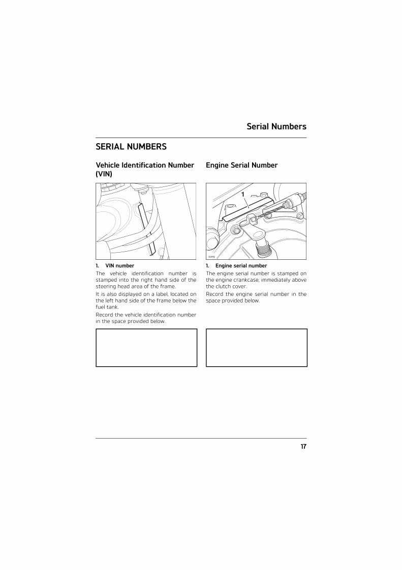
1. VIN numberThe vehicle identification number isstamped into the right hand side of thesteering head area of the frame. It is also displayed on a label, located onthe left hand side of the frame below thefuel tank.Record the vehicle identification numberin the space provided below.
Engine Serial Number
1. Engine serial numberThe engine serial number is stamped onthe engine crankcase, immediately abovethe clutch cover.Record the engine serial number in thespace provided below.
ccmy
1

Serial Numbers
18
This page intentionally left blank

General Information
19
GENERAL INFORMATION
Table of ContentsInstrument Panel Layout . . . . . . . . . . . . . . . . . . . . . . . . . . . . . . . . . . . . . . . . . . . . . . . . . . 22
Warning Lights . . . . . . . . . . . . . . . . . . . . . . . . . . . . . . . . . . . . . . . . . . . . . . . . . . . . . . . . . . . 23Engine Management System Malfunction Indicator Light . . . . . . . . . . . . . . . . . . . 23Low Oil Pressure Warning Light . . . . . . . . . . . . . . . . . . . . . . . . . . . . . . . . . . . . . . . . . 23High Coolant Temperature Warning Light . . . . . . . . . . . . . . . . . . . . . . . . . . . . . . . . . 24Alarm/Immobiliser Indicator Light. . . . . . . . . . . . . . . . . . . . . . . . . . . . . . . . . . . . . . . . 24ABS (Anti-Lock Brake System) Indicator Light . . . . . . . . . . . . . . . . . . . . . . . . . . . . . 25Traction Control (TC) Indicator Light . . . . . . . . . . . . . . . . . . . . . . . . . . . . . . . . . . . . . . 25Traction Control (TC) Disabled Warning Light . . . . . . . . . . . . . . . . . . . . . . . . . . . . . . 26Direction Indicators . . . . . . . . . . . . . . . . . . . . . . . . . . . . . . . . . . . . . . . . . . . . . . . . . . . . 26High Beam. . . . . . . . . . . . . . . . . . . . . . . . . . . . . . . . . . . . . . . . . . . . . . . . . . . . . . . . . . . . 26Daytime Running Lights (if fitted) . . . . . . . . . . . . . . . . . . . . . . . . . . . . . . . . . . . . . . . . 26Low Fuel . . . . . . . . . . . . . . . . . . . . . . . . . . . . . . . . . . . . . . . . . . . . . . . . . . . . . . . . . . . . . 26Neutral. . . . . . . . . . . . . . . . . . . . . . . . . . . . . . . . . . . . . . . . . . . . . . . . . . . . . . . . . . . . . . . 26Tyre Pressure Monitoring System (TPMS) Warning Light . . . . . . . . . . . . . . . . . . . . 27
Speedometer and Odometer . . . . . . . . . . . . . . . . . . . . . . . . . . . . . . . . . . . . . . . . . . . . . . . . 27
Tachometer . . . . . . . . . . . . . . . . . . . . . . . . . . . . . . . . . . . . . . . . . . . . . . . . . . . . . . . . . . . . . . 28
Trip Meter. . . . . . . . . . . . . . . . . . . . . . . . . . . . . . . . . . . . . . . . . . . . . . . . . . . . . . . . . . . . . . . . 28Trip Meter Reset . . . . . . . . . . . . . . . . . . . . . . . . . . . . . . . . . . . . . . . . . . . . . . . . . . . . . . 29
Clock Adjustment . . . . . . . . . . . . . . . . . . . . . . . . . . . . . . . . . . . . . . . . . . . . . . . . . . . . . . . . . 30
Changing Units (Imperial, US or Metric). . . . . . . . . . . . . . . . . . . . . . . . . . . . . . . . . . . . . . . 31
Service Interval Announcement (SIA) . . . . . . . . . . . . . . . . . . . . . . . . . . . . . . . . . . . . . . . . 32
Gear Change Lights . . . . . . . . . . . . . . . . . . . . . . . . . . . . . . . . . . . . . . . . . . . . . . . . . . . . . . . 33Gear Change Light Modes . . . . . . . . . . . . . . . . . . . . . . . . . . . . . . . . . . . . . . . . . . . . . . 33Setting Gear Change Light Limits . . . . . . . . . . . . . . . . . . . . . . . . . . . . . . . . . . . . . . . . 34Changing the Set Speed . . . . . . . . . . . . . . . . . . . . . . . . . . . . . . . . . . . . . . . . . . . . . . . . 35Setting Gear Change Lights to Off . . . . . . . . . . . . . . . . . . . . . . . . . . . . . . . . . . . . . . . 35
Riding Modes . . . . . . . . . . . . . . . . . . . . . . . . . . . . . . . . . . . . . . . . . . . . . . . . . . . . . . . . . . . . . 35RAIN Mode . . . . . . . . . . . . . . . . . . . . . . . . . . . . . . . . . . . . . . . . . . . . . . . . . . . . . . . . . . . 36ROAD Mode . . . . . . . . . . . . . . . . . . . . . . . . . . . . . . . . . . . . . . . . . . . . . . . . . . . . . . . . . . . 36SPORT Mode . . . . . . . . . . . . . . . . . . . . . . . . . . . . . . . . . . . . . . . . . . . . . . . . . . . . . . . . . . 36TRACK Mode . . . . . . . . . . . . . . . . . . . . . . . . . . . . . . . . . . . . . . . . . . . . . . . . . . . . . . . . . . 37RIDER Mode . . . . . . . . . . . . . . . . . . . . . . . . . . . . . . . . . . . . . . . . . . . . . . . . . . . . . . . . . . 37

General Information
20
Riding Mode Selection. . . . . . . . . . . . . . . . . . . . . . . . . . . . . . . . . . . . . . . . . . . . . . . . . . 38Selecting a Riding Mode – with the Motorcycle Stationary . . . . . . . . . . . . . . . . . . 39Selecting a Riding Mode – when Riding the Motorcycle . . . . . . . . . . . . . . . . . . . . . 40Setting the RIDER Mode Options. . . . . . . . . . . . . . . . . . . . . . . . . . . . . . . . . . . . . . . . . 43
Lap Timer . . . . . . . . . . . . . . . . . . . . . . . . . . . . . . . . . . . . . . . . . . . . . . . . . . . . . . . . . . . . . . . . 46Data Recording Mode . . . . . . . . . . . . . . . . . . . . . . . . . . . . . . . . . . . . . . . . . . . . . . . . . . 47New Lap Recording . . . . . . . . . . . . . . . . . . . . . . . . . . . . . . . . . . . . . . . . . . . . . . . . . . . . 48Data Retrieval Mode . . . . . . . . . . . . . . . . . . . . . . . . . . . . . . . . . . . . . . . . . . . . . . . . . . . 48
Coolant Temperature Gauge . . . . . . . . . . . . . . . . . . . . . . . . . . . . . . . . . . . . . . . . . . . . . . . . 49
Fuel Gauge. . . . . . . . . . . . . . . . . . . . . . . . . . . . . . . . . . . . . . . . . . . . . . . . . . . . . . . . . . . . . . . 49
Tyre Pressure Monitoring System (TPMS) . . . . . . . . . . . . . . . . . . . . . . . . . . . . . . . . . . . . 50Function . . . . . . . . . . . . . . . . . . . . . . . . . . . . . . . . . . . . . . . . . . . . . . . . . . . . . . . . . . . . . 50Tyre Pressure Sensor Serial Number . . . . . . . . . . . . . . . . . . . . . . . . . . . . . . . . . . . . . 50System Display . . . . . . . . . . . . . . . . . . . . . . . . . . . . . . . . . . . . . . . . . . . . . . . . . . . . . . . . .51Sensor Batteries . . . . . . . . . . . . . . . . . . . . . . . . . . . . . . . . . . . . . . . . . . . . . . . . . . . . . . .51Tyre Pressures . . . . . . . . . . . . . . . . . . . . . . . . . . . . . . . . . . . . . . . . . . . . . . . . . . . . . . . . 52Replacement Tyres . . . . . . . . . . . . . . . . . . . . . . . . . . . . . . . . . . . . . . . . . . . . . . . . . . . . 52
Ignition Key . . . . . . . . . . . . . . . . . . . . . . . . . . . . . . . . . . . . . . . . . . . . . . . . . . . . . . . . . . . . . . 53
Ignition Switch/Steering Lock. . . . . . . . . . . . . . . . . . . . . . . . . . . . . . . . . . . . . . . . . . . . . . . 54Engine Immobiliser. . . . . . . . . . . . . . . . . . . . . . . . . . . . . . . . . . . . . . . . . . . . . . . . . . . . . 54Ignition Switch Positions . . . . . . . . . . . . . . . . . . . . . . . . . . . . . . . . . . . . . . . . . . . . . . . 54
Brake and Clutch Lever Adjusters . . . . . . . . . . . . . . . . . . . . . . . . . . . . . . . . . . . . . . . . . . . 55Clutch Lever . . . . . . . . . . . . . . . . . . . . . . . . . . . . . . . . . . . . . . . . . . . . . . . . . . . . . . . . . . 55Brake Lever. . . . . . . . . . . . . . . . . . . . . . . . . . . . . . . . . . . . . . . . . . . . . . . . . . . . . . . . . . . 55
Right Handlebar Switches . . . . . . . . . . . . . . . . . . . . . . . . . . . . . . . . . . . . . . . . . . . . . . . . . . 56STOP Position . . . . . . . . . . . . . . . . . . . . . . . . . . . . . . . . . . . . . . . . . . . . . . . . . . . . . . . . . 56RUN Position. . . . . . . . . . . . . . . . . . . . . . . . . . . . . . . . . . . . . . . . . . . . . . . . . . . . . . . . . . 56START Position . . . . . . . . . . . . . . . . . . . . . . . . . . . . . . . . . . . . . . . . . . . . . . . . . . . . . . . . 56Hazard Warning Lights. . . . . . . . . . . . . . . . . . . . . . . . . . . . . . . . . . . . . . . . . . . . . . . . . 56
Left Handlebar Switches . . . . . . . . . . . . . . . . . . . . . . . . . . . . . . . . . . . . . . . . . . . . . . . . . . . 57SCROLL Button. . . . . . . . . . . . . . . . . . . . . . . . . . . . . . . . . . . . . . . . . . . . . . . . . . . . . . . . 57Horn Button . . . . . . . . . . . . . . . . . . . . . . . . . . . . . . . . . . . . . . . . . . . . . . . . . . . . . . . . . . 57Direction Indicator Switch . . . . . . . . . . . . . . . . . . . . . . . . . . . . . . . . . . . . . . . . . . . . . . 57MODE Button . . . . . . . . . . . . . . . . . . . . . . . . . . . . . . . . . . . . . . . . . . . . . . . . . . . . . . . . . 57Daytime Running Lights (DRL) Switch (if fitted) . . . . . . . . . . . . . . . . . . . . . . . . . . . . 57High Beam Button . . . . . . . . . . . . . . . . . . . . . . . . . . . . . . . . . . . . . . . . . . . . . . . . . . . . . 58

General Information
21
Fuel Requirement/Refuelling . . . . . . . . . . . . . . . . . . . . . . . . . . . . . . . . . . . . . . . . . . . . . . . 58Fuel Grade. . . . . . . . . . . . . . . . . . . . . . . . . . . . . . . . . . . . . . . . . . . . . . . . . . . . . . . . . . . . 58
Fuel Tank Cap . . . . . . . . . . . . . . . . . . . . . . . . . . . . . . . . . . . . . . . . . . . . . . . . . . . . . . . . . . . . 59
Filling the Fuel Tank . . . . . . . . . . . . . . . . . . . . . . . . . . . . . . . . . . . . . . . . . . . . . . . . . . . . . . . 60
Stand . . . . . . . . . . . . . . . . . . . . . . . . . . . . . . . . . . . . . . . . . . . . . . . . . . . . . . . . . . . . . . . . . . . 61Side Stand . . . . . . . . . . . . . . . . . . . . . . . . . . . . . . . . . . . . . . . . . . . . . . . . . . . . . . . . . . . . 61
Tool Kit and Owner’s Handbook . . . . . . . . . . . . . . . . . . . . . . . . . . . . . . . . . . . . . . . . . . . . . 61
Seats . . . . . . . . . . . . . . . . . . . . . . . . . . . . . . . . . . . . . . . . . . . . . . . . . . . . . . . . . . . . . . . . . . . . 62Seat Lock. . . . . . . . . . . . . . . . . . . . . . . . . . . . . . . . . . . . . . . . . . . . . . . . . . . . . . . . . . . . . 62Passenger Seat Removal . . . . . . . . . . . . . . . . . . . . . . . . . . . . . . . . . . . . . . . . . . . . . . . 62Passenger Seat Installation . . . . . . . . . . . . . . . . . . . . . . . . . . . . . . . . . . . . . . . . . . . . . 62Rider’s Seat Removal. . . . . . . . . . . . . . . . . . . . . . . . . . . . . . . . . . . . . . . . . . . . . . . . . . . 63Rider’s Seat Installation . . . . . . . . . . . . . . . . . . . . . . . . . . . . . . . . . . . . . . . . . . . . . . . . 63Seat Care. . . . . . . . . . . . . . . . . . . . . . . . . . . . . . . . . . . . . . . . . . . . . . . . . . . . . . . . . . . . . 63
Running-In. . . . . . . . . . . . . . . . . . . . . . . . . . . . . . . . . . . . . . . . . . . . . . . . . . . . . . . . . . . . . . . 64
Safe Operation. . . . . . . . . . . . . . . . . . . . . . . . . . . . . . . . . . . . . . . . . . . . . . . . . . . . . . . . . . . . 65Daily Safety Checks . . . . . . . . . . . . . . . . . . . . . . . . . . . . . . . . . . . . . . . . . . . . . . . . . . . . 65

General Information
22
Instrument Panel Layout
1. Clock2. Service interval indicator3. Speedometer4. Stop watch icon5. Fuel gauge6. Engine management Malfunction
Indicator Light (MIL)7. Gear change lights8. Left hand direction indicator light9. ABS warning light10. Tachometer 'red zone'11. Tyre pressure warning light (if Tyre
Pressure Monitoring System (TPMS) is fitted)
12. Right hand direction indicator light13. Neutral indicator light14. High beam indicator light15. Low fuel level indicator light
16. Daytime Running Lights (DRL) (if fitted)
17. Alarm/Immobiliser status indicator light (alarm is an accessory fit)
18. Traction Control (TC) disabled warning light
19. Traction Control (TC) indicator light20. Tachometer21. High coolant temperature warning
light22. Low oil pressure warning light23. Rider mode indicator light24. Trip meter indicator25. Tyre pressure display (if fitted)26. Gear position symbol27. Coolant temperature display28. Button B29. Button A
TCTC
2122 20 19 18 17
15
16
14
132 3 4 5 6 7 8 9 10 11 12
2324252627
28
29
1
General Information
23
Warning Lights
Engine Management System Malfunction Indicator Light
The Malfunction IndicatorLight (MIL) for the enginemanagement system illumi-nates when the ignition is
switched on (to indicate that it isworking) but should not becomeilluminated when the engine is running.If the malfunction indicator lightbecomes illuminated when the engine isrunning, this indicates that a fault hasoccurred in one or more of the systemscontrolled by the engine managementsystem. In such circumstances, theengine management system will switchto 'limp-home' mode, so that the journeymay be completed, if the fault is not sosevere that the engine will not run.
Note:
• If the malfunction indicator lightflashes when the ignition is switchedon, contact an authorised Triumphdealer as soon as possible to havethe situation rectified. In thesecircumstances the engine will notstart.
Low Oil Pressure Warning LightWith the engine running, if theengine oil pressure becomesdangerously low, the low oil
pressure warning light in thetachometer will illuminate.
The low oil pressure warning light in thetachometer will illuminate if the ignitionis switched on without running theengine.
Warning
Reduce speed and do not continue toride for longer than is necessary withthe malfunction indicator lightilluminated. The fault may adverselyaffect engine performance, exhaustemissions and fuel consumption.Reduced engine performance couldcause a dangerous riding condition,leading to loss of control and anaccident. Contact an authorisedTriumph dealer as soon as possible tohave the fault checked and rectified.
Caution
Stop the engine immediately if the lowoil pressure warning light illuminates.Do not restart the engine until thefault has been rectified.Severe engine damage will result fromrunning the engine when the low oilpressure warning light is illuminated.

General Information
24
High Coolant Temperature Warning Light
With the engine running, if theengine coolant temperaturebecomes dangerously high,the high coolant temperature
warning light in the tachometer willilluminate.
The high coolant temperature warninglight in the tachometer will illuminate ifthe ignition is switched on withoutrunning the engine.
Alarm/Immobiliser Indicator LightThis Triumph model is fittedwith an engine immobiliserwhich is activated when theignition switch is turned to
the OFF position. If the motorcycle isfitted with the accessory alarm, theimmobiliser will operate as normal butthe alarm/immobiliser light will operateas described below.
With Alarm FittedThe alarm/immobiliser light will onlyilluminate when the conditions describedin the accessory alarm instructions aremet.
Without Alarm FittedWhen the ignition switch is turned tothe OFF position, the alarm/immobiliserlight will flash on and off for 24 hours toshow that the engine immobiliser is on.When the ignition switch is turned tothe ON position the immobiliser and theindicator light will be off.
Caution
Stop the engine immediately if thehigh coolant temperature warninglight illuminates. Do not restart theengine until the fault has beenrectified.Severe engine damage will result fromrunning the engine when the highcoolant temperature warning light isilluminated.

General Information
25
ABS (Anti-Lock Brake System) Indicator Light
When the ignition switch isturned to the ON position, it isnormal that the ABS warninglight will flash on and off. The
light will continue to flash after enginestart-up until the motorcycle firstreaches a speed exceeding 6 mph(10 km/h) when it will go off.Unless the ABS system is disabled, orthere is a fault, it should not illuminateagain until the engine is restarted.If the indicator light becomes illuminatedat any other time while riding it indicatesthat the ABS has a malfunction thatrequires investigation.
See also Braking on page 71.
Traction Control (TC) Indicator LightThe TC indicator light is usedto indicate that the tractioncontrol system is active and isworking to limit rear wheel slip
during periods of hard acceleration orunder wet or slippery road conditions.
TC Indicator Light Operation:
TC Switched On:• Under normal riding conditions the
indicator light will remain off.• The indicator light will flash rapidly
when the traction control system isworking to limit rear wheel slipduring periods of hard accelerationor under wet or slippery roadconditions.
TC Switched Off:The indicator light will not illuminate.Instead the TC disabled warning light willbe illuminated (see page 26).
Note:
• Traction control will not function ifthere is a malfunction with the ABSsystem. The warning lights for theABS, traction control and the MIL willbe illuminated.
Warning
If the ABS is not functioning, the brakesystem will continue to function as anon-ABS braking system. Do not continue to ride for longerthan is necessary with the indicatorlight illuminated. Contact an authorised Triumph dealeras soon as possible to have the faultchecked and rectified. In this situationbraking too hard will cause the wheelsto lock resulting in loss of control andan accident.
TC

General Information
26
Traction Control (TC) Disabled Warning Light
The TC disabled warning lightshould not illuminate unlesstraction control is switched offor there is a malfunction,
If the warning light becomes illuminatedat any other time while riding, itindicates that the traction control has amalfunction that requires investigation.
Direction IndicatorsWhen the direction indicatorswitch is pushed to the left orright, the direction indicator
light will flash on and off at the samespeed as the direction indicators.
High BeamWhen the ignition is switchedon and the high beam buttonis pressed, the high beamwarning light will illuminate.
Daytime Running Lights (if fitted)When the ignition is switchedON and the daytime runninglights switch is set to ’daytime
running lights’, the daytime runninglights warning light will illuminate.
Low FuelThe low fuel indicator willilluminate when there areapproximately 3.5 litres of fuelremaining in the tank.
NeutralThe neutral warning lightindicates when thetransmission is in neutral (nogear selected). The warning
light will illuminate when thetransmission is in neutral with theignition switch in the ON position.
Warning
If the traction control is notfunctioning, care must be taken whenaccelerating and cornering onwet/slippery road surfaces to avoidrear wheel spin. Do not continue toride for longer than is necessary withthe Engine Management SystemMalfunction Indicator Light (MIL) andtraction control warning lightsilluminated. Contact an authorisedTriumph dealer as soon as possible tohave the fault checked.Hard acceleration and cornering inthis situation may cause the rearwheel to spin resulting in loss ofmotorcycle control and an accident.
TC

General Information
27
Tyre Pressure Monitoring System (TPMS) Warning Light
(Only on models fitted with TPMS)The tyre pressure warninglight works in conjunction withthe tyre pressure monitoringsystem (see page 50).
The warning light will only illuminatewhen the front or rear tyre pressure isbelow the recommended pressure. It willnot illuminate if the tyre is over inflated.When the warning light is illuminated,the TPMS symbol indicating which is thedeflated tyre and its pressure willautomatically be shown in the displayarea.
1. TPMS symbol2. Rear tyre, identified3. Tyre pressure
The tyre pressure at which the warninglight illuminates is temperaturecompensated to 20°C but the numericpressure display associated with it is not(see page 52). Even if the numeric displayseems at or close to the standard tyrepressure when the warning light is on, alow tyre pressure is indicated and apuncture is the most likely cause.
1 2
3
Warning
Stop the motorcycle if the tyrepressure warning light illuminates. Donot ride the motorcycle until the tyreshave been checked and the tyrepressures are at their recommendedpressure when cold.
General Information
28
Speedometer and OdometerThe digital speedometer indicates theroad speed of the motorcycle. The read-out displays the motorcycle road speedin increments of one kilometre (or mile)per hour.The odometer shows the total distancethat the motorcycle has travelled. Theelectronic odometer and trip meter arein the display screen.
TachometerThe tachometer shows the engine speedin revolutions per minute - rpm (r/min).At the end of the tachometer rangethere is the 'red zone'. Engine rpm (r/min) in the red zone isabove maximum recommended enginespeed and is also above the range forbest performance.
Trip Meter
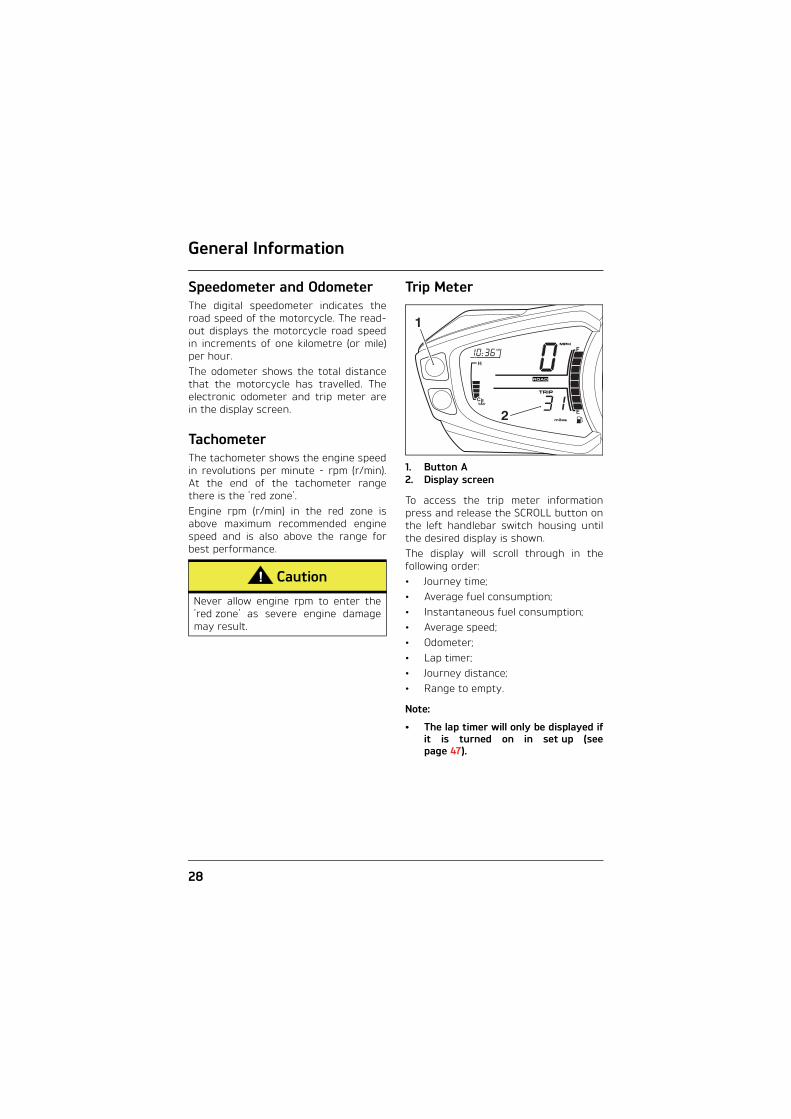
1. Button A2. Display screen
To access the trip meter informationpress and release the SCROLL button onthe left handlebar switch housing untilthe desired display is shown. The display will scroll through in thefollowing order:• Journey time;• Average fuel consumption;• Instantaneous fuel consumption;• Average speed;• Odometer;• Lap timer;• Journey distance;• Range to empty.
Note:
• The lap timer will only be displayed ifit is turned on in set up (seepage 47).
Caution
Never allow engine rpm to enter the'red zone' as severe engine damagemay result.
2
1

General Information
29
Each display provides the followinginformation all calculated since the tripmeter was last reset to zero:
Journey TimeThe total time elapsed.
Average Fuel ConsumptionAn indication of the average fuelconsumption. After being reset thedisplay will show dashes until0.1 miles/km has been covered.
Instantaneous Fuel ConsumptionAn indication of the fuel consumption atan instant in time.
Average SpeedThe average speed is calculated fromwhen the trip computer was last reset.After being reset the display will showdashes until 1 mile/km has been covered.
OdometerThe odometer shows the total distancethat the motorcycle has travelled.
Lap TimerThe lap timer shows the lap time,number of laps, average speed,maximum speed and distance travelled,depending if in recording or reviewingmode.
Journey DistanceThe total journey distance travelled.
Range to EmptyThis is an indication of the probabledistance that can be travelled on theremaining fuel in the tank.
Trip Meter ResetTo reset the trip meter, select anddisplay the trip meter then press theSCROLL button for one second. Afterone second, the trip meter will reset tozero.
Note:
• When the trip meter is reset to zero,the journey time, average fuelconsumption and average speed willalso be set to zero for the trip meter.
To exit the trip meter, press and releasethe SCROLL button until the desireddisplay is shown.
Warning
Do not attempt to switch betweenodometer and trip meter displaymodes or reset the trip meter with themotorcycle in motion as this may leadto loss of motorcycle control and anaccident.

General Information
30
Clock Adjustment
To reset the clock, with the motorcyclestationary and in neutral turn theignition to the ON position. Press andrelease button 'A' until SEtUP is shown inthe display screen. Press button 'B’ untilt-SEt will be shown.Press button 'B' again and either 24 Hror 12 Hr clock will be shown. Pressbutton 'A' to select the desired clockdisplay and then press button 'B'. Thehour display will start to flash and theword Hour is shown in the displayscreen.To reset the hour display, make surethat the hour display is still flashing andthe word Hour is shown. Press button 'A'to change the setting. Each individualbutton press will change the setting byone digit. If the button is held, thedisplay will continuously scroll throughin single digit increments.When the correct hour display is shown,press button 'B'. The minutes display willbegin to flash and the word Min isshown in the display screen. Theminutes display is adjusted in the sameway as for the hours.
Once both hours and minutes arecorrectly set, press button 'B' to confirmand t-SEt will be shown in the displayscreen. Press and release button 'A' untilREtURn is shown then press button 'B'.
1. Hours read-out2. Minutes read-out3. Display screen (Hour selected for
adjustment)4. Button B5. Button A
Warning
Do not attempt to adjust the clockwith the motorcycle in motion as thismay lead to loss of motorcycle controland an accident.
3
4
5 1 2

General Information
31
Changing Units (Imperial, US or Metric)Units has four selectable display modes.Each display provides the followinginformation:
mpg (Imperial gallons)The speedometer and odometer will readin miles. The fuel consumption will bemeasured in imperial gallons.
mpg US (US gallons) The speedometer and odometer will readin miles. The fuel consumption will bemeasured in US gallons.
L/100 km (Metric)The speedometer and odometer will readin kilometres. The fuel consumption willbe measured in litres of fuel per 100 km.
km/L (Metric)The speedometer and odometer will readin kilometres. The fuel consumption willbe measured in kilometers per litre offuel.
To access the units display, with themotorcycle stationary and in neutralturn the ignition to the ON position.Press and release button 'A' until SEtUPis shown in the display screen thenpress button 'B'.Press and release button 'A' until UnitSis shown then press button 'B'.
1. Button A2. Button B3. Display screen
Press and release button 'A' until thedesired display is shown. The display willscroll through in the following order: • mpg - Imperial gallons;• mpg US - US gallons;• L/100 km - Metric;• km/L - Metric.
Warning
Do not attempt to change the unitsdisplay with the motorcycle in motionas this may lead to loss of motorcyclecontrol and an accident.
3
1
2

General Information
32
Models without TPMS: Press button 'B'and do not touch buttons 'A' or 'B' againuntil UnitS is shown in the displayscreen. When UnitS is shown in thedisplay screen, press and releasebutton 'A' until REtURn is shown thenpress button 'B'. Trip will be shown in thedisplay screen.Models with TPMS: Press button 'B' anddo not touch buttons 'A' or 'B' again untilPSI or bAr is displayed. Press andrelease button 'A' until the desired tyrepressure units are shown. Press button 'B' and wait until UnitS isdisplayed, then press button ’A’ andwhen REtURn is displayed pressbutton ’B’. Trip will be shown in thedisplay screen.
ReturnSelect REtURn to return to the maindisplay.
Service Interval Announcement (SIA)The Service Interval Announcement (SIA)shows the total distance that themotorcycle has remaining before aservice is required. If the service isoverdue, the distance will be displayedas a negative number.
1. Service indicator2. Remaining distance
When the ignition is switched on and thedistance to the next service is 500 miles(800 km) or less, the service symbol willbe displayed for three seconds and theclock will show the distance remainingbefore the next service. When the remaining distance is 0 miles(0 km) the service symbol will remain onuntil the service has been carried outand the system has been reset by yourauthorised Triumph dealer.
1
2

General Information
33
To access the SIA display, with themotorcycle stationary and in neutral,turn the ignition to the ON position.Press and release button 'A' until SEtUPis shown in the display screen thenpress button 'B'. Press and release button 'A' until SIA isshown.To exit the SIA display, press and releasebutton ’A’ until REtURn is shown in thedisplay screen, then press button B.
Gear Change LightsThe gear change lights provide a visualindication of when to change gear. Thegear change lights are all coloured blue.
1. Gear change lights2. Display screen3. Button A4. Button B
Gear Change Light ModesThe gear change lights have fourprogrammable operating modes asdescribed below:• 3 LED mode: The first three lights
illuminate when the set limit isreached, and remain illuminated untilthe engine speed drops below theset limit.
• 6 LED mode: All six lights illuminatewhen the set limit is reached, andremain illuminated until the enginespeed drops below the set limit.
• SE mode: The lights will progressivelyilluminate in 250 rpm incrementsuntil the set limit is reached. At theset limit all six lights will beilluminated.
• OFF mode: The gear change lightsare turned OFF.
TCTC
1
4 2
3

General Information
34
Setting Gear Change Light LimitsThe gear change lights will not operatebelow 3,500 rpm to avoid the lightsoperating at idle.To change the gear change light modes,with the motorcycle stationary and inneutral turn the ignition to the ONposition.Press and release button 'A' until SEtUPis shown in the display screen thenpress button 'B'. Press and release button 'A' until SHIFtis shown then press button 'B'. Thecurrent mode will be displayed and thecorresponding gear change lights willilluminate.Press and release button 'A' until thedesired gear change light mode is shownthen press button 'B'. The display willscroll through in the following order:• 6 (6 LED mode);• 3 (3 LED mode);• SE (Sequential mode);• OFF (Gear change lights off).
Note:
• The motorcycle is delivered from thefactory with the gear change lightset to the 6 LED mode at 3,500 rpm.
1. Gear change lights2. Display screen (6 mode shown)3. Button A4. Button B
When the gear change light mode hasbeen selected, the tachometer needlewill move round to the last set position.The rpm will be shown in the displayscreen with the 1,000 units flashing.
1. RPM 1,000 units2. Button A3. Button B
TCTC
1
4 2
3
TCTC
2
3 1

General Information
35
Changing the Set SpeedTo change the setting in increments of500 rpm, press button 'A'. Eachindividual press of button 'A' will thenincrease the setting in increments of500 rpm, up to the maximum rpm limit.When the maximum rpm limit is reached,the setting will return to 3,500 rpm.
Note:
• If the rpm 1,000 units is set to themaximum rpm limit, SHIFt will beshown.
When the correct setting is shown,pressing button 'B' will confirm thesetting, SHIFt will be shown in thedisplay screen and all the gear changelights will flash. Press and releasebutton 'A' until REtURn is shown in thedisplay screen then press button 'B'.
Setting Gear Change Lights to OffTo select the OFF mode, make sure OFFis shown in the display screen. Press button 'B' and SHIFt will be shownin the display screen. Press and releasebutton 'A' until REtURn is shown in thedisplay screen then press button 'B'.
1. Gear change lights2. Display screen (OFF mode shown)
Riding ModesThe riding mode system allowsadjustment of the throttle response(MAP), Anti-lock Brake System (ABS) andTriumph Traction Control (TTC) settingsto suit differing road conditions andrider preferences.Riding modes can be convenientlyselected using the MODE button on theleft handlebar switch housing, whilst themotorcycle is stationary or moving.
1. MODE buttonPress and release the MODE button toselect one of the following riding modes(see page 38).• RAIN mode – non-adjustable• ROAD mode – non-adjustable• SPORT mode – non-adjustable• TRACK mode – non-adjustable• RIDER mode – adjustable.
Press and hold the MODE button showsthe RIDER mode set up menu (seepage 43).
TCTC
1
2
MODE
i
cixb2
1

General Information
36
RAIN ModeThe RAIN mode provides optimal MAP,ABS and TTC settings for normal roaduse in rain conditions.
ROAD ModeThe ROAD mode provides optimal MAP,ABS and TTC settings for normal roaduse.
SPORT ModeThe SPORT mode provides optimal MAP,ABS and TTC settings for normal sportuse.
System Settings
MAP Rain – Reduced throttle response when compared to the Road setting, for wet or slippery conditions.
ABS Road – Optimal ABS setting for road use.
TTC Rain – Optimal TTC setting for road use in rain conditions, allows minimal rear wheel slip.
System Settings
MAP Road – Standard throttle response.
ABS Road – Optimal ABS setting for road use.
TTC Road – Optimal TTC setting for road use.
System Settings
MAP Sport – Increased throttle response when compared to the Road setting.
ABS Road – Optimal ABS setting for road use.
TTC Road – Optimal TTC setting for road use, allows minimal rear wheel slip.

General Information
37
TRACK ModeThe TRACK mode provides optimal MAP,ABS and TTC settings for light trackriding.
RIDER ModeThe RIDER mode is fully adjustable andallows the rider to select MAP, ABS andTTC options to suit road conditions orpersonal preferences.The MAP, ABS and TTC options availablefor selection are as follows:
System Settings
MAP Sport – Optimal throttle response setting for off-road use.
ABS Track – Optimal ABS setting for track use.Front Wheel – The ABS system allows increased front wheel slip when compared to the Road setting.Rear Wheel – The ABS system is disabled for the rear wheel, allowing it to lock under heavy braking.The ABS warning light will flash slowly (see page 25).
TTC Track – TTC is set up for track use, allowing increased rear wheel slip when compared to the Road setting.
Warning
The TRACK mode is not intended fornormal, on-road riding.Riding on-road with the TRACK modeactivated can produce instability whenbraking if the ABS cuts in and underacceleration if the TTC intervenes,leading to loss of motorcycle controland an accident.
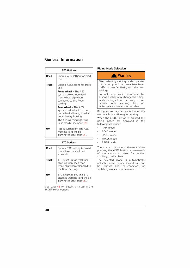
MAP Options
Rain Reduced throttle response when compared to the Road setting, for wet or slippery conditions.
Road Standard throttle response.
Sport Increased throttle response when compared to the Road setting.
Warning
The TRACK ABS and TTC options arenot intended for normal, on-roadriding.Riding on-road with the TRACK ABSand TTC options activated canproduce instability when braking if theABS cuts in and under acceleration ifthe TTC intervenes, leading to loss ofmotorcycle control and an accident.
General Information
38
See page 43 for details on setting theRIDER Mode options.
Riding Mode Selection
Riding modes may be selected when themotorcycle is stationary or moving.When the MODE button is pressed theriding modes are displayed in thefollowing sequence:• RAIN mode• ROAD mode• SPORT mode• TRACK mode• RIDER mode.
There is a one second time-out whenpressing the MODE button between eachof the modes to allow for furtherscrolling to take place.The selected mode is automaticallyactivated once the one second time-outhas elapsed, and the conditions forswitching modes have been met.
ABS Options
Road Optimal ABS setting for road use.
Track Optimal ABS setting for track use:Front Wheel – The ABS system allows increased front wheel slip when compared to the Road setting.Rear Wheel – The ABS system is disabled for the rear wheel, allowing it to lock under heavy braking.The ABS warning light will flash slowly (see page 25).
Off ABS is turned off. The ABS warning light will be illuminated (see page 25).
TTC Options
Road Optimal TTC setting for road use, allows minimal rear wheel slip.
Track TTC is set up for track use, allowing increased rear wheel slip when compared to the Road setting.
Off TTC is turned off. The TTC disabled warning light will be illuminated (see page 26).
Warning
After selecting a riding mode, operatethe motorcycle in an area free fromtraffic to gain familiarity with the newsettings. Do not loan your motorcycle toanyone as they may change the ridingmode settings from the one you arefamiliar with, causing loss ofmotorcycle control and an accident.

General Information
39
Note:
• The riding mode will default to ROADwhen the ignition is switched ON if:The TRACK mode was active the lasttime the ignition was switched off; orThe RIDER mode was active the lasttime the ignition was switched offwith ABS and/or TTC set to TRACKor Off.
• Otherwise, the last selected ridingmode will be remembered andactivated when the ignition isswitched ON.
Selecting a Riding Mode – with the Motorcycle Stationary
Note:
• If the ignition is switched on and theengine not started, the instrumentswill display the odometer for fiveseconds.
Press and release the MODE button onthe left handlebar switch housing untilthe desired riding mode is flashing in thedisplay.
1. Selected riding mode (flashing)2. Current (active) riding mode
Note:
• The selected riding mode isautomatically activated one secondafter the MODE button is pressed, ifthe following conditions are met:
With the Engine Off• The ignition is switched ON• The engine stop switch is in the RUN
position.
21

General Information
40
With the Engine Running• Neutral gear is selected or the clutch
is pulled in.
Once the MAP, ABS and TTC settingshave changed, the selected riding modewill be displayed and the previous modewill no longer be shown.
1. Selected riding mode
Selecting a Riding Mode – when Riding the Motorcycle
1
Warning
The selection of riding modes whilstthe motorcycle is in motion requiresthe rider to allow the motorcycle tocoast (motorcycle moving, enginerunning, throttle closed, clutch leverpulled in and no brakes applied) for abrief period of time.Riding mode selection whilst themotorcycle is in motion should only beattempted:• At low speed• In traffic free areas• On straight and level roads or
surfaces• In good road and weather
conditions• Where it is safe to allow the
motorcycle to briefly coast.
Riding mode selection whilst themotorcycle is in motion MUST NOT beattempted:• At high speeds• Whilst riding in traffic• During cornering or on winding
roads or surfaces• On steeply inclined roads or
surfaces• In poor road/weather conditions• Where it is unsafe to allow the
motorcycle to coast.
Failure to observe this importantwarning will lead to loss of motorcyclecontrol and an accident.
General Information
41
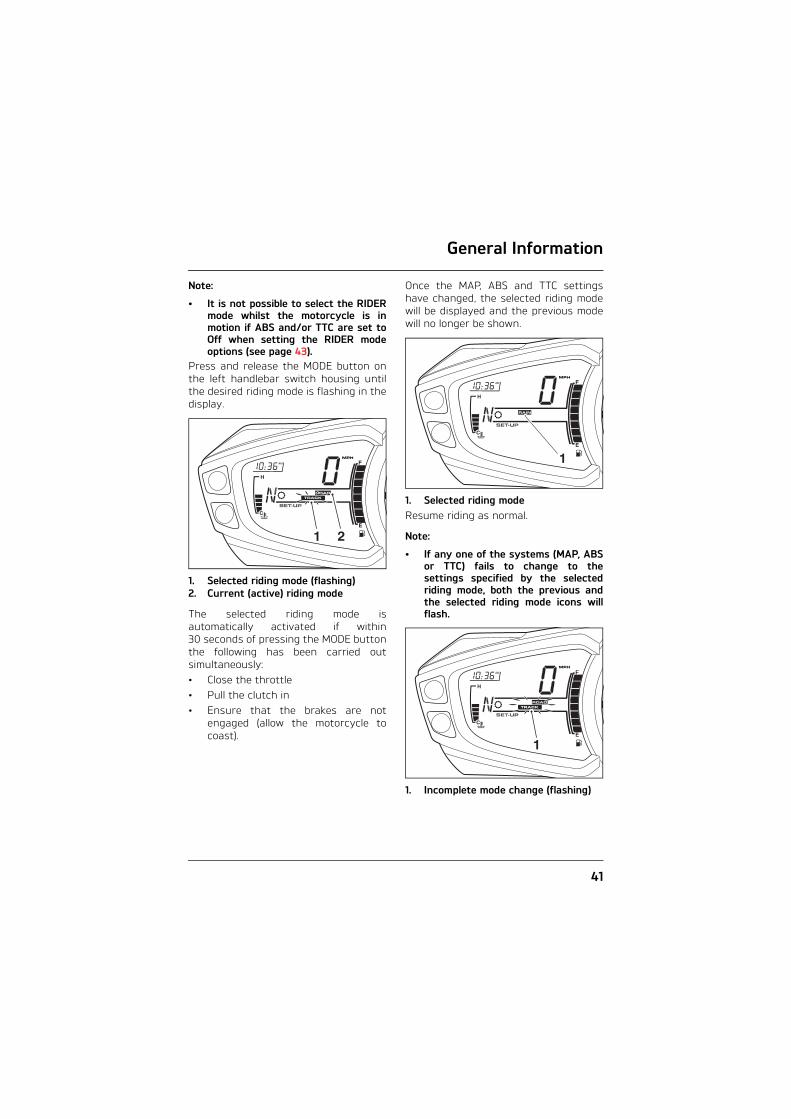
Note:
• It is not possible to select the RIDERmode whilst the motorcycle is inmotion if ABS and/or TTC are set toOff when setting the RIDER modeoptions (see page 43).
Press and release the MODE button onthe left handlebar switch housing untilthe desired riding mode is flashing in thedisplay.
1. Selected riding mode (flashing)2. Current (active) riding mode
The selected riding mode isautomatically activated if within30 seconds of pressing the MODE buttonthe following has been carried outsimultaneously: • Close the throttle• Pull the clutch in• Ensure that the brakes are not
engaged (allow the motorcycle tocoast).
Once the MAP, ABS and TTC settingshave changed, the selected riding modewill be displayed and the previous modewill no longer be shown.
1. Selected riding modeResume riding as normal.
Note:
• If any one of the systems (MAP, ABSor TTC) fails to change to thesettings specified by the selectedriding mode, both the previous andthe selected riding mode icons willflash.
1. Incomplete mode change (flashing)
21
1
1

General Information
42
The flashing of two riding mode iconstogether indicates that MAP, ABS or TTCsettings specified by the selected ridingmode have not been correctly selected.In this case the MIL, ABS or TTC warninglight(s) may be illuminated depending onthe current state of each system.In the event of an incomplete ridingmode change:• Safely bring the motorcycle to a stop• Select neutral gear• Turn the ignition OFF and then back
ON again• Select the desired riding mode• Restart the engine and continue
riding.
Note:
• If the mode icons are not shownwhen the ignition switch is in the ONposition, ensure the engine stopswitch is in the RUN position.
Warning
Do not stop the engine using theignition switch or engine stop switchwhilst the motorcycle is moving.Always bring the motorcycle to a stopsafely and engage neutral gear priorto stopping the engine. Stopping the engine by turning off theignition or engine stop switch whilstthe motorcycle is moving can lock therear wheel causing loss of motorcyclecontrol and an accident.
Caution
The engine should not be stopped byturning the ignition switch to theOFF position when the motorcycle ismoving. The engine stop switch is foremergency use only. Stopping the engine when themotorcycle is moving may causedamage to motorcycle componentsleading to loss of motorcycle controland an accident.

General Information
43
Setting the RIDER Mode Options
Note:
• During setup, ABS and TTC can beactivated or de-activated in theRIDER mode.
• If the RIDER mode is currentlyselected, changes to the MAP, ABSand TTC systems will becomeimmediately active.
• If the ROAD or TRACK modes areselected the RIDER settings will notbecome active until the RIDER modeis selected (see page 38).
To set the RIDER mode options; with themotorcycle stationary and in neutral,turn the ignition to the ON position.• Press and release the MODE button
on the left handlebar switch housinguntil RIDER mode is selected.
• Press and hold the MODE button untilMAP is shown in the display screen.
or alternatively:• Press and release button ’A’ until
SEtUP is shown in the displayscreen. Press button ’B’ to confirm.
• Press and release button ’A’ untilRIdER is displayed in the lowerinstrument display, then pressbutton ’B’ to confirm.
RIdER Displayed
MAP OptionsPress button ’A’ and choose one of theavailable MAP options:• Rain• Road• Sport.
Rain Option Shown
Press button ’B’ to confirm the selection. ABS is now shown in the display screen.

General Information
44
ABS OptionsPress button ’A’ and choose one of theavailable ABS options:• Road• Track• Off.
Road Option Shown
Press button ’B’ to confirm the selection. TTC is now shown in the display screen.
TTC OptionsPress button ’A’ and choose one of theavailable TTC options: • Rain• Road• Track• Off.
Track Option Shown
Warning
If the ABS is disabled, the brakesystem will function as a non-ABSbraking system. In this situationbraking too hard will cause the wheelsto lock, and may result in loss ofmotorcycle control and an accident.
Warning
If the traction control is disabled, themotorcycle will handle as normal butwithout traction control. In thissituation accelerating too hard onwet/slippery road surfaces may causethe rear wheel to slip, and may resultin loss of motorcycle control and anaccident.

General Information
45
Press button ’B’ to confirm the selection. RIdER is now shown in the display.
RIdER Displayed
Press button ’B’ and the REtURn screenis displayed.
REtURn Displayed
Press button ’B’ to confirm.
The trip screen and the current ridingmode is displayed.
Current riding mode
To select a riding mode see page 38.

General Information
46
Lap Timer
1. Lap number2. Stop watch icon3. Lap timer information4. Button A5. Button B
To access the lap timer information, withthe motorcycle stationary and in neutralturn the ignition to the ON position. Press and release button ’A’ until SEtUPis shown in the display screen. Pressbutton ’B’ to confirm. Press and release button ’B’ to view thedifferent lap timer information in thefollowing sequence:• Lap time• Maximum speed• Average speed• Distance travelled.
Lap TimeThe elapsed time of the lap (the lapnumber will be shown in thespeedometer display). Information isrecorded for each lap since the lastreset.
Note:
• The lap timer will reset to zero after100 minutes.
Maximum SpeedThe maximum speed achieved per lapand the lap number.
Average SpeedThe average speed per lap and the lapnumber.
Distance TravelledThe distance travelled per lap and thelap number.
Number of LapsThe number of recorded laps since thelast reset is shown at the top of thedisplay. A maximum of 50 laps can bestored by the lap timer.
Note:
• The speed and distance will beshown in kilometres or miles,according to the units displayed bythe speedometer.
Warning
Do not attempt to switch between laptimer display modes with themotorcycle in motion as this may leadto loss of motorcycle control and anaccident.
2
35
4 1

General Information
47
Turning the Lap Timer On or OffTo switch the lap timer on or off, withthe motorcycle stationary and in neutralturn the ignition to the ON position.Press button ’A’ on the left handlebarswitch housing until LAP is shown.Press and release button 'A' until SEtUPis shown in the display screen. Thenpress button 'B'.Press and release button 'A' until LAP isshown then press button 'B'. ON or OFFwill flash in the display screen.Press button 'A' to select either ON orOFF then press button 'B'. Do not touchbuttons 'A' or 'B' until LAP is shown inthe display. Then press and releasebutton 'A' until REtURn is shown thenpress button 'B’. SEtUP is shown in the display screen.Press button ’A’ until REtURn is shownand then press button ’B’.
Data Recording Mode
1. Lap number2. Stop watch icon3. Lap timer4. Button A5. Button B
Note:
• The data recording mode and thedata retrieval mode will only operatewhen the lap timer (LAP) is turnedon.
To select the data recording mode, turnthe ignition to the ON position.Press and release the SCROLL buttonuntil LAP is shown in the screen thenpress the SCROLL button for more thanone second. L01 and a stop watch iconwill be shown in the speedometerdisplay, and the lap timer will be shownin the display screen.Pressing the SCROLL button (with theengine running only) will start the laptimer. The display will show the lap timein minutes, seconds and hundredths of asecond, and the stop watch icon is on.
2
35
4 1

General Information
48
New Lap Recording
1. SCROLL buttonAt the end of the lap, pressing theSCROLL button again will register thestart of a new lap. The display will showthe last lap time for five seconds, thenthe new lap number for five seconds. After this time, the speedometer displaywill show the current lap number andthe display screen will show the currentlap time.
Data Retrieval ModeThe data retrieval mode can be accessedin one of two ways:• With the ignition in the ON position,
from the lap timer display, pressbutton 'B'.
• From the Data Recording Mode, withthe engine running and themotorcycle stationary, press theSCROLL button for two seconds. Thiswill return the display to the LAPdisplay. Then press button 'B'.
Note:
• The data retrieval mode cannot beaccessed whilst the motorcycle is inmotion.
When the data retrieval mode isaccessed, the lap time for the first lapwill be displayed. The lap number will bedisplayed in the speedometer displayposition. Press and release button 'A' until thedesired lap (up to a maximum of 50 laps)is displayed.Press and release button 'B' to scrollthrough the lap data.
Lap Timer Reset and ExitTo reset the lap timer and exit lap timer,press button 'B' for two seconds. Aftertwo seconds, the lap timer will reset andLAP will be shown in the display screen.This will delete the stored data for allstored laps.To exit the data retrieval mode withoutresetting the lap timer, press button 'A'for two second, LAP will be shown in thedisplay screen. Press and releasebutton 'A' to the desired display.
MODE
i
cixb3
1

General Information
49
Coolant Temperature Gauge
1. Coolant temperature gaugeThe coolant temperature gaugeindicates the temperature of the enginecoolant.When the ignition is switched on, alleight bars of the display will be shown.When the engine is started from coldthe display will show one bar. As thetemperature increases more bars will beshown in the display. When the engine isstarted from hot the display will showthe relevant number of bars, dependanton engine temperature.The normal temperature range isbetween three and five bars.If the coolant temperature becomes toohigh the display will show eight bars andwill start to flash. The high coolanttemperature warning light in thetachometer will also be illuminated.
Fuel Gauge
1. Fuel gauge2. Button B
The fuel gauge indicates the amount offuel in the tank.With the ignition switched on, thenumber of bars shown in the displayindicates the level of fuel.When the fuel tank is full all eight barsare displayed and when empty, no barsare displayed. Other gauge markingsindicate intermediate fuel levels betweenfull and empty.When two bars are displayed the lowfuel warning light will illuminate. Thisindicates there are approximately4.5 litres of fuel remaining in the tankand you should refuel at the earliestopportunity. If a trip meter display isshown, the range to empty display canbe selected by pressing and releasingbutton 'B' until it is shown.After refuelling, the fuel gauge andrange to empty information will beupdated only while riding themotorcycle. Depending on the ridingstyle, updating could take up to fiveminutes.
1 1
2
General Information
50
Tyre Pressure Monitoring System (TPMS)(Only on models fitted with TPMS)
FunctionTyre pressure sensors are fitted to thefront and rear wheels. These sensorsmeasure the air pressure inside the tyreand transmit pressure data to theinstruments. These sensors will nottransmit the data until the motorcycle istravelling at a speed greater than12 mph (20 km). Two dashes will beshown in the display area until the tyrepressure signal is received.The Tyre Pressure Monitoring System(TPMS) is an accessory fitted item andmust be fitted by your authorisedTriumph dealer. The TPMS display on the instrumentpack will only be activated when thesystem has been fitted.An adhesive label will be fitted to thewheel rim to indicate the position of thetyre pressure sensor which is near thevalve.
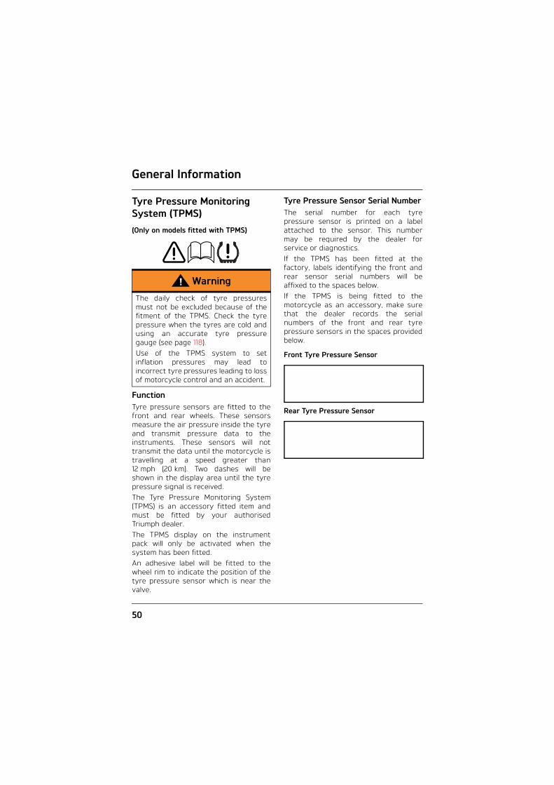
Tyre Pressure Sensor Serial NumberThe serial number for each tyrepressure sensor is printed on a labelattached to the sensor. This numbermay be required by the dealer forservice or diagnostics.If the TPMS has been fitted at thefactory, labels identifying the front andrear sensor serial numbers will beaffixed to the spaces below.If the TPMS is being fitted to themotorcycle as an accessory, make surethat the dealer records the serialnumbers of the front and rear tyrepressure sensors in the spaces providedbelow.
Front Tyre Pressure Sensor
Rear Tyre Pressure Sensor
Warning
The daily check of tyre pressuresmust not be excluded because of thefitment of the TPMS. Check the tyrepressure when the tyres are cold andusing an accurate tyre pressuregauge (see page 118).Use of the TPMS system to setinflation pressures may lead toincorrect tyre pressures leading to lossof motorcycle control and an accident.

General Information
51
System Display
1. TPMS symbol2. Front tyre, identified3. Rear tyre, identified4. Tyre pressure display5. Button A6. Button B
To access the tyre pressure display, turnthe ignition to the ON position.Press and release button 'A' until PSI orbAR is shown in the display screen.Press and release button 'B' to selectthe front or rear tyre pressure.When the tyre pressure monitoringsystem has been selected, —— PSI orbAR will be shown in the display screenuntil the motorcycle is travelling at aspeed greater than 12 mph (20 km) andthe tyre pressure signal is received.To exit the tyre pressure display, pressand release button 'A' to the desireddisplay.
Sensor BatteriesWhen the battery voltage in a pressuresensor is low, LO bAt will be displayedand the TPMS symbol will indicate whichwheel sensor has the low batteryvoltage. If the batteries are completelyflat, only dashes will be shown in thedisplay screen, the red TPMS warninglight will be on and the TPMS symbol willflash continuously. Contact yourauthorised Triumph dealer to have thesensor replaced and the new serialnumber recorded in the spaces providedon page 50.
1. TPMS symbol2. Front tyre, identified3. Rear tyre, identified4. TPMS warning light5. Tyre pressure display
With the ignition switch turned to theON position, if the TPMS symbol flashescontinuously and the TPMS warninglight remains on there is a fault with theTPMS system. Contact your authorisedTriumph dealer to have the faultrectified.
Warning
Do not attempt to switch betweenfront and rear tyre display modes withthe motorcycle in motion as this maylead to loss of motorcycle control andan accident.
1 2
4
3
5
6TC
TC
1 2 3 4
5

General Information
52
Tyre PressuresThe tyre pressures shown on yourinstrument panel indicate the actualtyre pressure at the time of selectingthe display. This may differ from theinflation pressure set when the tyresare cold because tyres become warmerduring riding, causing the air in the tyreto expand and the pressure to increase.The cold inflation pressures specified byTriumph take account of this.Owners must only adjust tyre pressureswhen the tyres are cold using anaccurate tyre pressure gauge (seepage 118), and must not use the tyrepressure display on the instruments.
Replacement TyresWhen replacing tyres, make sure theyare aware that tyre pressure sensorsare fitted to the wheels and always havean authorised Triumph dealer fit yourtyres (see page 120).
Warning
The tyre pressure monitoring systemis not to be used as a tyre pressuregauge when adjusting the tyrepressures. For correct tyre pressures,always check the tyre pressures whenthe tyres are cold and using anaccurate tyre pressure gauge (seepage 118).Use of the TPMS system to setinflation pressures may lead toincorrect tyre pressures leading toloss of motorcycle control and anaccident.
Caution
Do not use anti puncture fluid or anyother item likely to obstruct air flow tothe TPMS sensor’s orifices. Anyblockage to the air pressure orifice ofthe TPMS sensor during operation willcause the sensor to become blocked,causing irreparable damage to theTPMS sensor assembly. Damage caused by the use ofanti puncture fluid or incorrectmaintenance is not considered amanufacturing defect and will not becovered under warranty. Always have your tyres fitted by yourauthorised Triumph dealer and informthem that tyre pressure sensors arefitted to the wheel.

General Information
53
Ignition Key
1. Key number tagIn addition to operating the steeringlock/ignition switch, the ignition key isrequired to operate the seat lock andfuel tank cap.When the motorcycle is delivered fromthe factory, two keys are suppliedtogether with a small tag bearing thekey number. Make a note of the keynumber and store the spare key and keynumber tag in a safe place away fromthe motorcycle.A transponder is fitted within the key toturn off the engine immobiliser. Toensure the immobiliser functionscorrectly, always have only one of theignition keys near the ignition switch.Having two ignition keys near the switchmay interrupt the enable signal betweenthe transponder and the engineimmobiliser. In this situation the engineimmobiliser will remain on until one ofthe ignition keys is removed.
Always get replacement keys from yourauthorised Triumph dealer. Replacementkeys must be 'paired' with themotorcycle’s immobiliser by yourauthorised Triumph dealer.
1
ceom
Caution
Do not store the spare key with themotorcycle as this will reduce allaspects of security.

General Information
54
Ignition Switch/Steering Lock
1. Ignition switch/Steering lock2. LOCK position3. OFF position4. ON position5. PARK position
Engine ImmobiliserThe ignition barrel housing acts as theantenna for the engine immobiliser.When the ignition switch is turned tothe OFF position and the ignition keyremoved, the engine immobiliser is on(see page 24). The engine immobiliser isturned off when the ignition key is in theignition switch and it is turned to the ONposition.
Ignition Switch PositionsThis is a four position, key operatedswitch. The key can be removed fromthe switch only when it is in the OFF,LOCK or P (PARK) position.
TO LOCK: Turn the steering fully to theleft, turn the key to the OFF position,push and fully release the key, thenrotate it to the LOCK position.PARKING: Turn the key from the LOCKposition to the P position. The steeringwill remain locked.
Note:
• Do not leave the steering lock in theP position for long periods of time asthis will cause the battery todischarge.
PU
SH
P
OFF ON
3
2
5
1
4
Warning
For reasons of security and safety,always move the ignition switch to theOFF position and remove the key whenleaving the motorcycle unattended.Any unauthorised use of themotorcycle may cause injury to therider, other road users andpedestrians and may also causedamage to the motorcycle.
Warning
With the key in the LOCK or P positionthe steering will become locked.Never turn the key to the LOCK or Ppositions while the motorcycle ismoving as this will cause the steeringto lock. Locked steering will cause lossof motorcycle control and an accident.

General Information
55
Brake and Clutch Lever AdjustersAn adjuster is fitted to both the frontbrake and clutch levers. The adjustersallow the distance from the handlebar tothe levers to be changed to suit thespan of the operator's hands.
Clutch Lever
1. Clutch lever2. Adjuster wheel3. Triangular mark
To adjust the clutch lever, push the leverforward and turn the adjuster wheel toalign one of the numbered positions withthe triangular mark on the lever holder.The distance from the handlebar grip tothe released lever is shortest when setto number four and longest when set tonumber one.
Brake Lever
1. Brake lever2. Adjusting screw
To adjust the brake lever, push the leverforward and turn the adjusting screw into increase the distance or out toshorten the distance from thehandlebar.
1
3 2
4
1
2
cggr_1
3
Warning
Do not attempt to adjust the leverswith the motorcycle in motion as thismay lead to loss of motorcycle controland an accident.After adjusting the levers, operate themotorcycle in an area free from trafficto gain familiarity with the new leversetting. Do not loan your motorcycleto anyone as they may change thelever setting from the one you arefamiliar with causing loss of control oran accident.
cggq
1
2

General Information
56
Right Handlebar Switches
1. Engine start/stop switch2. STOP position3. RUN position4. START position5. Hazard warning light switch
STOP PositionThe STOP position is for emergency use.If an emergency arises which requiresthe engine to be stopped, move theengine start/stop switch to the STOPposition.
Note:
• Although the engine stop positionstops the engine, it does not turn offall the electrical circuits and maycause difficulty in restarting theengine due to a discharged battery.Ordinarily, only the ignition switchshould be used to stop the engine.
RUN PositionIn addition to the ignition switch beingturned to the ON position, the enginestart/stop switch must be in the RUNposition for the motorcycle to operate.
START PositionThe START position operates the electricstarter. For the starter to operate, theclutch lever must be pulled to thehandlebar and the engine start/stopswitch in the START position.
Note:
• Even if the clutch lever is pulled tothe handlebar, the starter will notoperate if the side stand is down anda gear is engaged.
Hazard Warning LightsTo turn the hazard warning lights on oroff, press and release the hazardwarning light switch.The ignition must be switched ON for thehazard warning lights to function.
Caution
Do not leave the ignition switch in theON position unless the engine isrunning as this may cause damage toelectrical components and willdischarge the battery.
cite_1
4 1
5
2
3

General Information
57
Left Handlebar Switches
1. SCROLL button2. Horn button3. Direction indicator switch4. MODE button5. Daytime Running Lights (DRL) switch
(if fitted)6. High beam button
SCROLL ButtonThe SCROLL button is used to operatethe following functions of theinstruments:• Trip meter functions (see page 29)• Odometer functions (see page 28)• Lap timer functions (if switched on)
(see page 46).
Horn ButtonWhen the horn button is pushed, withthe ignition switch turned to the ONposition, the horn will sound.
Direction Indicator SwitchWhen the direction indicator switch ispushed to the left or right, thecorresponding direction indicators willflash on and off.The indicators can be cancelledmanually. To manually turn off theindicators, press and release theindicator switch in the central position.
MODE ButtonThe MODE button is used to selectdifferent riding modes. The riding modesystem allows adjustment of the throttleresponse (MAP), Anti-lock Brake System(ABS) and Triumph Traction Control (TTC)settings to suit differing road conditionsand rider preferences.Press and release the MODE button toselect one of the different riding modesavailable (see page 35 for moreinformation).
Daytime Running Lights (DRL) Switch (if fitted)
Note:
• The daytime running lights aremanually operated. They are notautomatic.
The daytime running lights or dip beamcan be selected with the DaytimeRunning Light (DRL) switch. To select the daytime running lights,push the DRL switch forward. To select dip beam, push the DRL switchrearwards. When the daytime running lights areturned on, the daytime running lightsindicator light will illuminate in theinstrument panel.
MODE
i
cixb
1
2 34
56

General Information
58
High Beam ButtonWhen the high beam button is pressedthe high beam will be switched on. Eachpress of the button will swap betweendip and high beam.
Note:
• If daytime running lights are fittedto the motorcycle, the high beambutton has additional functionality.
If the DRL switch is in the daytimerunning lights position, then press andhold the high beam button to turn thehigh beam on. It will remain on as long asthe button is held in and will turn off assoon as the button is released.
Note:
• A lighting on/off switch is not fittedto this model. The position light, rearlight and license plate light allfunction automatically when theignition is turned to the ON position.
• The headlight will function when theignition switch is turned to the ONposition.
• The headlight will go off whilepressing the starter button until theengine starts.
Fuel Requirement/Refuelling
Fuel Grade
Your Triumph engine is designed to useunleaded fuel and will give optimumperformance if the correct grade of fuelis used. Always use unleaded fuel withan octane rating of 95 RON.
Caution
In all countries except Australia andNew Zealand the exhaust system isfitted with a catalytic converter tohelp reduce exhaust emission levels.The catalytic converter can bepermanently damaged if themotorcycle is allowed to run out offuel or if the fuel level is allowed to getvery low. Always make sure you haveadequate fuel for your journey.
Caution
The use of leaded fuel is illegal in mostcountries, states or territories. Use ofleaded fuel will damage the catalyticconverter (if fitted).
Pb

General Information
59
Fuel Tank Cap
1. Fuel tank cap2. Key
To open the fuel tank cap, lift up the flapcovering the lock itself. Insert the keyinto the lock and turn the key clockwise. To close and lock the cap, push the capdown into place with the key inserted,until the lock 'clicks' into place. Withdrawthe key and close the key cover.
Warning
To help reduce hazards associatedwith refuelling, always observe thefollowing fuel safety instructions:Petrol (fuel) is highly flammable andcan be explosive under certainconditions. When refuelling, turn theignition switch to the OFF position.Do not smoke.Do not use a mobile telephone.Make sure the refuelling area is wellventilated and free from any source offlame or sparks. This includes anyappliance with a pilot light.Never fill the tank until the fuel levelrises into the filler neck. Heat fromsunlight or other sources may causethe fuel to expand and overflowcreating a fire hazard.After refuelling always check that thefuel filler cap is correctly closed andlocked.Because petrol (fuel) is highlyflammable, any fuel leak or spillage, orany failure to observe the safetyadvice given above will lead to a firehazard, which could cause damage toproperty, injury to persons or death.
Caution
Closing the cap without the keyinserted will damage the cap, tank andlock mechanism.
12
cbmm

General Information
60
Filling the Fuel TankAvoid filling the tank in rainy or dustyconditions where airborne material cancontaminate the fuel.
Fill the fuel tank slowly to help preventspillage. Do not fill the tank to a levelabove the bottom of the filler neck. Thiswill ensure there is enough air space toallow for fuel expansion if the fuel insidethe tank expands through absorption ofheat from the engine or from directsunlight.
1. Maximum fuel level2. Fuel filler neck3. Air space
After refuelling always check that thefuel filler cap is correctly closed andlocked.
Caution
Contaminated fuel may cause damageto fuel system components.
1 2 3
cbdf
Warning
Overfilling the tank can lead to fuelspillage.If fuel is spilled, thoroughly clean upthe spillage immediately and disposeof the materials used safely.Take care not to spill any fuel on theengine, exhaust pipes, tyres or anyother part of the motorcycle. Because fuel is highly flammable, anyfuel leak or spillage, or any failure toobserve the safety advice given abovemay lead to a fire hazard, which couldcause damage to property and injuryor death to persons.Fuel spilled near to, or onto the tyreswill reduce the tyre's ability to grip theroad. This will result in a dangerousriding condition potentially causingloss of motorcycle control and anaccident.
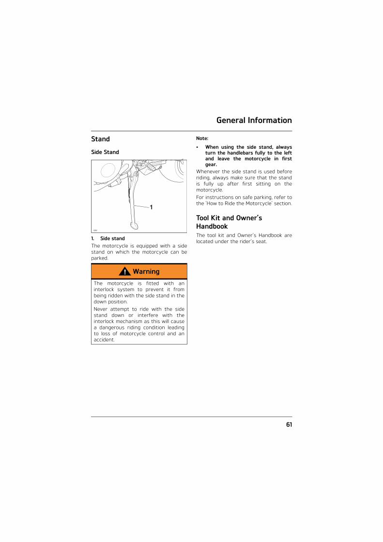
General Information
61
Stand
Side Stand
1. Side standThe motorcycle is equipped with a sidestand on which the motorcycle can beparked.
Note:
• When using the side stand, alwaysturn the handlebars fully to the leftand leave the motorcycle in firstgear.
Whenever the side stand is used beforeriding, always make sure that the standis fully up after first sitting on themotorcycle.For instructions on safe parking, refer tothe 'How to Ride the Motorcycle' section.
Tool Kit and Owner’s HandbookThe tool kit and Owner’s Handbook arelocated under the rider’s seat.
Warning
The motorcycle is fitted with aninterlock system to prevent it frombeing ridden with the side stand in thedown position. Never attempt to ride with the sidestand down or interfere with theinterlock mechanism as this will causea dangerous riding condition leadingto loss of motorcycle control and anaccident.
1
cgey
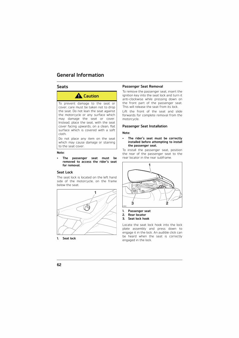
General Information
62
Seats
Note:
• The passenger seat must beremoved to access the rider’s seatfor removal.
Seat LockThe seat lock is located on the left handside of the motorcycle, on the framebelow the seat.
1. Seat lock
Passenger Seat RemovalTo remove the passenger seat, insert theignition key into the seat lock and turn itanti-clockwise while pressing down onthe front part of the passenger seat.This will release the seat from its lock. Lift the front of the seat and slideforwards for complete removal from themotorcycle.
Passenger Seat Installation
Note:
• The rider’s seat must be correctlyinstalled before attempting to installthe passenger seat.
To install the passenger seat, positionthe rear of the passenger seat to therear locator in the rear subframe.
1. Passenger seat2. Rear locator3. Seat lock hook
Locate the seat lock hook into the lockplate assembly and press down toengage it in the lock. An audible click canbe heard when the seat is correctlyengaged in the lock.
Caution
To prevent damage to the seat orcover, care must be taken not to dropthe seat. Do not lean the seat againstthe motorcycle or any surface whichmay damage the seat or cover.Instead, place the seat, with the seatcover facing upwards, on a clean, flatsurface which is covered with a softcloth.Do not place any item on the seatwhich may cause damage or stainingto the seat cover.
1
cgex
1
23L0003

General Information
63
Rider’s Seat RemovalRemove the passenger seat as describedon page 62. A tool is located at the frontof the passenger seat. Using the tool,remove the two fixings securing therider’s seat to the lock plate.
1. Fixings2. Rider’s seat
To detach the rider’s seat, slide the seatrearwards and lift the rear of the seat.Disengage the locators from the frame,and the front bracket from below thefuel tank hinge.
Rider’s Seat InstallationTo install the rider’s seat, position theseat’s front bracket under the fuel tankhinge and the rear location into positionin the rear subframe.
1. Rider’s seat2. Front bracket3. Fuel tank hinge
Secure the rider’s seat to the seat lockplate with the two fixings. Tighten to 9 Nm.
Note:
• The fuel tank support is located onthe underside of the rider’s seat, seepage 97.
Seat CareTo prevent damage to the seat or seatcover, care must be taken not to drop orlean the seat against any surface whichmay damage the seat or its cover.See page 134 for seat cleaninginformation.
Warning
To prevent detachment of the seatduring riding, after fitting alwaysgrasp the seat and pull firmlyupwards. If the seat is not correctlysecured in the lock, it will detach fromthe lock. A loose or detached seatcould cause loss of motorcycle controland an accident.
21
L0001
1
1
2
3
L0002
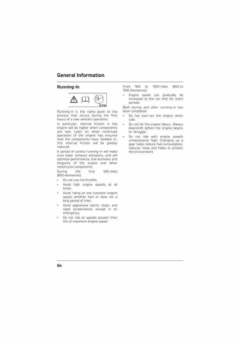
General Information
64
Running-In
Running-in is the name given to theprocess that occurs during the firsthours of a new vehicle's operation. In particular, internal friction in theengine will be higher when componentsare new. Later on, when continuedoperation of the engine has ensuredthat the components have 'bedded in',this internal friction will be greatlyreduced.A period of careful running-in will makesure lower exhaust emissions, and willoptimise performance, fuel economy andlongevity of the engine and othermotorcycle components.During the first 500 miles(800 kilometres):• Do not use full throttle.• Avoid high engine speeds at all
times.• Avoid riding at one constant engine
speed, whether fast or slow, for along period of time.
• Avoid aggressive starts, stops, andrapid accelerations, except in anemergency.
• Do not ride at speeds greater than3/4 of maximum engine speed.
From 500 to 1000 miles (800 to1500 kilometres):• Engine speed can gradually be
increased to the rev limit for shortperiods.
Both during and after running-in hasbeen completed:• Do not over-rev the engine when
cold.• Do not let the engine labour. Always
downshift before the engine beginsto 'struggle'.
• Do not ride with engine speedsunnecessarily high. Changing up agear helps reduce fuel consumption,reduces noise and helps to protectthe environment.

General Information
65
Safe Operation
Daily Safety Checks
Check the following items each daybefore you ride. The time required isminimal, and these checks will helpensure a safe, reliable ride.If any irregularities are found duringthese checks, refer to the Maintenanceand Adjustment section or see yourauthorised Triumph dealer for the actionrequired to return the motorcycle to asafe operating condition.
Check:Fuel: Adequate supply in tank, no fuelleaks (see page 58).Engine Oil: Correct level on dipstick. Addcorrect specification oil as required. Noleaks from the engine or oil cooler (seepage 91).Drive Chain: Correct adjustment (seepage 100).Tyres/Wheels: Correct inflationpressures (when cold). Treaddepth/wear, tyre/wheel damage,punctures etc. (see page 118).
Nuts, Bolts, Fasteners: Visually checkthat steering and suspensioncomponents, axles, and all controls areproperly tightened or fastened. Inspectall areas for loose/damaged fixings.Steering Action: Smooth but not loosefrom lock to lock. No binding of any ofthe control cables (see page 109).Brakes: Pull the brake lever and push thebrake pedal to check for correctresistance. Investigate any lever/pedalwhere the travel is excessive beforemeeting resistance, or if either controlfeels spongy in operation (see page 104).Brake Pads: There should be more than1.0 mm of friction material remaining onthe front brake pads and more than1.5 mm for the rear (see page 104).Brake Fluid Levels: No brake fluidleakage. Brake fluid levels must bebetween the MAX and MIN marks onboth reservoirs (see page 105).Front Forks: Smooth action. No leaksfrom fork seals (see page 110).Throttle: Throttle grip free play 2 - 3 mmat all steering angles. Make sure thatthe throttle grip returns to the idleposition without sticking (see page 98).Clutch: Smooth operation and correctcable free play (see page 99) at allsteering angles.Coolant: No coolant leakage. Check thecoolant level in the expansion tank(when the engine is cold) (see page 94).Electrical Equipment: All lights and hornfunction correctly (see page 53).Engine Stop: Stop switch turns theengine off (see page 68).Stand: Returns to the fully up positionby spring tension. Return springs notweak or damaged (see page 61).
Warning
Failure to perform these checks everyday before you ride may result inserious motorcycle damage or anaccident causing serious injury ordeath.

General Information
66
This page intentionally left blank

How to Ride the Motorcycle
67
HOW TO RIDE THE MOTORCYCLE
Table of ContentsTo Stop the Engine . . . . . . . . . . . . . . . . . . . . . . . . . . . . . . . . . . . . . . . . . . . . . . . . . . . . . . . . 68
To Start the Engine . . . . . . . . . . . . . . . . . . . . . . . . . . . . . . . . . . . . . . . . . . . . . . . . . . . . . . . 68
Moving Off . . . . . . . . . . . . . . . . . . . . . . . . . . . . . . . . . . . . . . . . . . . . . . . . . . . . . . . . . . . . . . . 69
Changing Gears. . . . . . . . . . . . . . . . . . . . . . . . . . . . . . . . . . . . . . . . . . . . . . . . . . . . . . . . . . . 70Quickshifter - Speed Triple S (if fitted) and Speed Triple R . . . . . . . . . . . . . . . . . . . 70
Braking . . . . . . . . . . . . . . . . . . . . . . . . . . . . . . . . . . . . . . . . . . . . . . . . . . . . . . . . . . . . . . . . . . .71ABS (Anti-Lock Brake System). . . . . . . . . . . . . . . . . . . . . . . . . . . . . . . . . . . . . . . . . . . 73
Parking . . . . . . . . . . . . . . . . . . . . . . . . . . . . . . . . . . . . . . . . . . . . . . . . . . . . . . . . . . . . . . . . . . 74
Considerations for High-Speed Operation . . . . . . . . . . . . . . . . . . . . . . . . . . . . . . . . . . . . 75General . . . . . . . . . . . . . . . . . . . . . . . . . . . . . . . . . . . . . . . . . . . . . . . . . . . . . . . . . . . . . . 76Steering . . . . . . . . . . . . . . . . . . . . . . . . . . . . . . . . . . . . . . . . . . . . . . . . . . . . . . . . . . . . . . 76Luggage. . . . . . . . . . . . . . . . . . . . . . . . . . . . . . . . . . . . . . . . . . . . . . . . . . . . . . . . . . . . . . 76Brakes . . . . . . . . . . . . . . . . . . . . . . . . . . . . . . . . . . . . . . . . . . . . . . . . . . . . . . . . . . . . . . . 76Tyres . . . . . . . . . . . . . . . . . . . . . . . . . . . . . . . . . . . . . . . . . . . . . . . . . . . . . . . . . . . . . . . . 76Fuel . . . . . . . . . . . . . . . . . . . . . . . . . . . . . . . . . . . . . . . . . . . . . . . . . . . . . . . . . . . . . . . . . 77Engine Oil . . . . . . . . . . . . . . . . . . . . . . . . . . . . . . . . . . . . . . . . . . . . . . . . . . . . . . . . . . . . 77Coolant. . . . . . . . . . . . . . . . . . . . . . . . . . . . . . . . . . . . . . . . . . . . . . . . . . . . . . . . . . . . . . . 77Electrical Equipment . . . . . . . . . . . . . . . . . . . . . . . . . . . . . . . . . . . . . . . . . . . . . . . . . . . 77Miscellaneous . . . . . . . . . . . . . . . . . . . . . . . . . . . . . . . . . . . . . . . . . . . . . . . . . . . . . . . . . 77

How to Ride the Motorcycle
68
To Stop the Engine
1. Engine stop switch2. START position3. Neutral indicator light4. ON position5. Ignition switch
Close the throttle completely.Select neutral.Turn the ignition switch off.Select first gear.Support the motorcycle on a firm, levelsurface with the side stand.Lock the steering.
To Start the EngineCheck that the engine stop switch is inthe RUN position.Make sure the transmission is in neutral.Pull the clutch lever fully into thehandlebar.Turn the ignition switch on.
Note:
• When the ignition is switched on, thetachometer needle will quickly sweepfrom zero to maximum and thenreturn to zero. The instrumentwarning lights will illuminate and willthen go off (except those whichnormally remain on until the enginestarts - see page 23. It is notnecessary to wait for the needle toreturn to zero before starting theengine.
Leaving the throttle fully closed, pushthe starter button until the enginestarts.Slowly release the clutch lever.
TCTC
OFF ON
1
2
3
P 45
Caution
The engine should normally bestopped by turning the ignition switchto the OFF position. The engine stopswitch is for emergency use only. Do not leave the ignition switched onwith the engine stopped. Electricaldamage may result.
How to Ride the Motorcycle
69
The motorcycle is equipped with starterlockout switches. The switches preventthe electric starter from operating whenthe transmission is not in neutral withthe side stand down. If the throttle is open then the bike willnot start.If the side stand is extended whilst theengine is running, and the transmissionis not in neutral then the engine willstop regardless of clutch position.
Moving OffPull in the clutch lever and select firstgear. Open the throttle a little and letout the clutch lever slowly. As the clutchstarts to engage, open the throttle alittle more, allowing enough enginespeed to avoid stalling.
Warning
Never start the engine or run theengine in a confined area. Exhaustfumes are poisonous and can causeloss of consciousness and deathwithin a short period of time. Alwaysoperate your motorcycle in theopen-air or in an area with adequateventilation.
Caution
Do not operate the startercontinuously for more thanfive seconds as the starter motor willoverheat and the battery will becomedischarged. Wait 15 seconds betweeneach operation of the starter to allowfor cooling and recovery of batterypower.Do not let the engine idle for longperiods as this may lead tooverheating which will cause damageto the engine.
Caution
The low oil pressure warning lightshould go out shortly after the enginestarts.If the low oil pressure warning lightstays on after starting the engine,stop the engine immediately andinvestigate the cause. Running theengine with low oil pressure will causesevere engine damage.
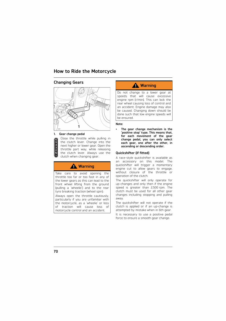
How to Ride the Motorcycle
70
Changing Gears
1. Gear change pedalClose the throttle while pulling inthe clutch lever. Change into thenext higher or lower gear. Open thethrottle part way, while releasingthe clutch lever. Always use theclutch when changing gear.
Note:
• The gear change mechanism is the'positive stop' type. This means that,for each movement of the gearchange pedal, you can only selecteach gear, one after the other, inascending or descending order.
Quickshifter (if fitted) A race-style quickshifter is available asan accessory on this model. Thequickshifter will trigger a momentaryengine cut to allow gears to engage,without closure of the throttle oroperation of the clutch.The quickshifter will only operate forup-changes and only then if the enginespeed is greater than 2,500 rpm. Theclutch must be used for all other gearchanges including stopping and pullingaway.The quickshifter will not operate if theclutch is applied or if an up-change isattempted by mistake when in 6th gear.It is necessary to use a positive pedalforce to ensure a smooth gear change.
Warning
Take care to avoid opening thethrottle too far or too fast in any ofthe lower gears as this can lead to thefront wheel lifting from the ground(pulling a 'wheelie') and to the reartyre breaking traction (wheel spin).Always open the throttle cautiously,particularly if you are unfamiliar withthe motorcycle, as a 'wheelie' or lossof traction will cause loss ofmotorcycle control and an accident.
1cgez
Warning
Do not change to a lower gear atspeeds that will cause excessiveengine rpm (r/min). This can lock therear wheel causing loss of control andan accident. Engine damage may alsobe caused. Changing down should bedone such that low engine speeds willbe ensured.

How to Ride the Motorcycle
71
Braking
1. Front brake lever 1. Rear brake pedal
Warning
WHEN BRAKING, OBSERVE THE FOLLOWING:
Close the throttle completely, leavingthe clutch engaged to allow theengine to help slow down themotorcycle.Change down one gear at a time suchthat the transmission is in first gearwhen the motorcycle comes to acomplete stop.When stopping, always apply bothbrakes at the same time. Normally thefront brake should be applied a littlemore than the rear.Change down or fully disengage theclutch as necessary to keep theengine from stalling.Never lock the brakes, as this maycause loss of control of the motorcycleand an accident.
1
cghm
Warning
For emergency braking, disregarddown changing, and concentrate onapplying the front and rear brakes ashard as possible without skidding.Riders should practice emergencybraking in a traffic-free area. (See ABSwarnings.)Triumph strongly recommends that allriders take a course of instruction,which includes advice on safe brakeoperation. Incorrect brake techniquecould result in loss of control and anaccident.
cggg
1

How to Ride the Motorcycle
72
Warning
For your safety, always exerciseextreme caution when braking,(whether or not ABS is fitted),accelerating or turning as anyincautious action can cause loss ofcontrol and an accident. Independentuse of the front or rear brakesreduces overall braking performance.Extreme braking may cause eitherwheel to lock, reducing control of themotorcycle and causing an accident(see ABS warning).When possible, reduce speed or brakebefore entering a turn as closing thethrottle or braking in mid-turn maycause wheel slip leading to loss ofcontrol and an accident.When riding in wet or rainy conditions,or on loose surfaces, the ability tomanoeuvre and stop will be reduced.All of your actions should be smoothunder these conditions. Suddenacceleration, braking or turning maycause loss of control and an accident.
Warning
When descending a long, steepgradient, use engine braking by downchanging and use the brakesintermittently. Continuous brakeapplication can overheat the brakesand reduce their effectiveness.Riding with your foot on the brakepedal or your hands on the brake levermay actuate the brake light, giving afalse indication to other road users. Itmay also overheat the brake, reducingbraking effectiveness.Do not coast with the engine switchedoff, and do not tow the motorcycle. Thetransmission is pressure-lubricatedonly when the engine is running.Inadequate lubrication may causedamage or seizure of the transmission,which can lead to sudden loss ofmotorcycle control and an accident.

How to Ride the Motorcycle
73
ABS (Anti-Lock Brake System) ABS Warning LightWhen the ignition switch isturned to the ON position, it isnormal for the ABS warninglight to flash on and off (see
page 25). If the ABS warning light isconstantly illuminated it indicates thatthe ABS function is not availablebecause:• the ABS has been disabled by the
rider;• the ABS has a malfunction that
requires investigation.If the indicator light becomes illuminatedwhile riding, it indicates that the ABShas a malfunction that requiresinvestigation.
Note:
• Normally, the rider will perceive ABSoperation as a harder feel or apulsation of the brake lever andpedal. As the ABS is not anintegrated braking system and itdoes not control both the front andrear brake at the same time, thispulsation may be felt in the lever, thepedal or both.
• The ABS may be activated by suddenupward or downward changes in theroad surface.
Warning
ABS prevents the wheels from locking,therefore maximising the effectivenessof the braking system in emergenciesand when riding on slippery surfaces.The potentially shorter brakingdistances ABS allows under certainconditions are not a substitute forgood riding practice.Always ride within the legal speedlimit.Never ride without due care andattention and always reduce speed inconsideration of weather, road andtraffic conditions.Take care when cornering. If thebrakes are applied in a corner, ABS willnot be able to counteract the weightand momentum of the motorcycle.This can result in loss of control andan accident.Under some circumstances it ispossible that a motorcycle equippedwith ABS may require a longerstopping distance than an equivalentmotorcycle without ABS.

How to Ride the Motorcycle
74
Parking
Select neutral and turn the ignitionswitch to the OFF position.Lock the steering to help prevent theft.Always park on a firm, level surface toprevent the motorcycle from falling.When parking on a hill, always parkfacing uphill to prevent the motorcyclefrom rolling off the stand. Engage firstgear to prevent the motorcycle frommoving. On a lateral (sideways) incline, alwayspark such that the incline naturallypushes the motorcycle towards the sidestand.Do not park on a lateral (sideways)incline of greater than 6° and never parkfacing downhill.
Note:
• When parking near traffic at night,or when parking in a location whereparking lights are required by law,leave the tail, license plate andposition lights on by turning theignition switch to P (Park).
Do not leave the switch in the P positionfor long periods of time as this willdischarge the battery.
Warning
If the ABS is not functioning, the brakesystem will continue to function as anon-ABS braking system. Do notcontinue to ride for longer than isnecessary with the indicator lightilluminated. Contact an authorisedTriumph dealer as soon as possible tohave the fault checked and rectified.In this situation, braking too hard willcause the wheels to lock resulting inloss of control and an accident.
Warning
The ABS warning light will illuminatewhen the rear wheel is driven at highspeed for more than 30 seconds whenthe motorcycle is on a stand. Thisreaction is normal.When the ignition is switched off andthe motorcycle is re-started, thewarning light will illuminate until themotorcycle reaches a speed exceeding19 mph (30 km/h).
Warning
The ABS computer operates bycomparing the relative speed of thefront and rear wheels. Use of non-recommended tyres can affect wheelspeed and cause the ABS function notto operate, potentially leading to lossof control and an accident inconditions where the ABS wouldnormally function.
ccms_2

How to Ride the Motorcycle
75
Considerations for High-Speed OperationWarning
Do not park on a soft or on a steeplyinclined surface. Parking under theseconditions may cause the motorcycleto fall over causing damage toproperty and personal injury.
Warning
Petrol is extremely flammable and canbe explosive under certain conditions.If parking inside a garage or otherstructure, be sure it is well ventilatedand the motorcycle is not close to anysource of flame or sparks. Thisincludes any appliance with a pilotlight.Failure to follow the above advice maycause a fire resulting in damage toproperty or personal injury.
Warning
The engine and exhaust system will behot after riding. DO NOT park wherepedestrians and children are likely totouch the motorcycle.Touching any part of the engine orexhaust system when hot may causeunprotected skin to become burnt.
Warning
This Triumph motorcycle should beoperated within the legal speed limitsfor the particular road travelled.Operating a motorcycle at high speedscan be potentially dangerous since thetime available to react to given trafficsituations is greatly reduced as roadspeed increases. Always reduce speedin consideration of weather and trafficconditions.
Warning
Only operate this Triumph motorcycleat high speed in closed-courseon-road competition or on closed-course racetracks. High-speedoperation should only then beattempted by riders who have beeninstructed in the techniquesnecessary for high-speed riding andare familiar with the motorcycle'scharacteristics in all conditions.High-speed operation in any othercircumstances is dangerous and willlead to loss of motorcycle control andan accident.

How to Ride the Motorcycle
76
GeneralMake sure the motorcycle has beenmaintained according to the scheduledmaintenance chart.
SteeringCheck that the handlebar turnssmoothly without excessive free play ortight spots. Make sure that the controlcables do not restrict the steering in anyway.
LuggageMake certain that any luggagecontainers are closed, locked andsecurely fitted to the motorcycle.
BrakesCheck that the front and rear brakes arefunctioning properly.
TyresHigh-speed operation is hard on tyres,and tyres that are in good condition arecrucial to riding safely. Examine theiroverall condition, inflate to the correctpressure (when the tyres are cold), andcheck the wheel balance. Securely fit thevalve caps after checking tyrepressures. Observe the informationgiven in the Maintenance andSpecification sections on tyre checkingand tyre safety.
Warning
The handling characteristics of amotorcycle at high speed may varyfrom those you are familiar with atlegal road speeds. Do not attempt high-speed operationunless you have received sufficienttraining and have the required skillsas a serious accident may result fromincorrect operation.
Warning
The items listed are extremelyimportant and must never beneglected. A problem, which may notbe noticed at normal operatingspeeds, may be greatly exaggeratedat high speeds.

How to Ride the Motorcycle
77
FuelHave sufficient fuel for the increasedfuel consumption that will result fromhigh-speed operation.
Engine OilMake certain that the engine oil level iscorrect. Make sure that the correctgrade and type of oil is used whentopping up.
CoolantCheck that the coolant level is at theupper level line in the expansion tank.(Always check the level with the enginecold.)
Electrical EquipmentMake certain that the headlight,rear/brake light, direction indicators,horn, etc. all work properly.
MiscellaneousVisually check that all fixings are tight.
Caution
In all countries except Australia andNew Zealand the exhaust system isfitted with a catalytic converter tohelp reduce exhaust emission levels.The catalytic converter can bepermanently damaged if themotorcycle is allowed to run out offuel or if the fuel level is allowed to getvery low. Always make sure you haveadequate fuel for your journey.

How to Ride the Motorcycle
78
This page intentionally left blank

Accessories, Loading and Passengers
79
ACCESSORIES, LOADING AND PASSENGERSThe addition of accessories and carryingof additional weight can affect themotorcycle's handling characteristicscausing changes in stability andnecessitating a reduction in speed. The following information has beenprepared as a guide to the potentialhazards of adding accessories to amotorcycle and carrying passengers andadditional loads.
Warning
Incorrect loading may result in anunsafe riding condition leading to anaccident. Always make sure that any loadscarried are evenly distributed on bothsides of the motorcycle. Make surethat the load is correctly secured suchthat it will not move around while themotorcycle is in motion.Always check the load securityregularly (though not while themotorcycle is in motion) and makesure that the load does not extendbeyond the rear of the motorcycle.Never exceed the maximum vehicleloading weight of 195 kg.This maximum loading weight is madeup from the combined weight of therider, passenger, any accessoriesfitted and any load carried.
Warning
Do not install accessories or carryluggage that impairs the control of themotorcycle. Make sure that you havenot adversely affected the visibility ofany lighting component, roadclearance, banking capability (i.e. leanangle), control operation, wheel travel,front fork movement, visibility in anydirection, or any other aspect of themotorcycle's operation.
Warning
Never ride an accessory equippedmotorcycle, or a motorcycle carrying apayload of any kind, at speeds above80 mph (130 km/h). In either/both ofthese conditions, speeds in excess of80 mph (130 km/h) should not beattempted even where the legal speedlimit permits this.The presence of accessories and/orpayload will cause changes in thestability and handling of themotorcycle.Failure to allow for changes inmotorcycle stability may lead to lossof control or an accident. Rememberthat the 80 mph (130 km/h) absolutelimit will reduce by the fitting ofnon-approved accessories, incorrectloading, worn tyres, overall motorcyclecondition and poor road or weatherconditions.

Accessories, Loading and Passengers
80
Warning
This motorcycle must not be operatedabove the legal road speed limitexcept in authorised closed-courseconditions.
Warning
Only operate this Triumph motorcycleat high speed in closed-courseon-road competition or on closed-course racetracks. High-speedoperation should only then beattempted by riders who have beeninstructed in the techniquesnecessary for high-speed riding andare familiar with the motorcycle'scharacteristics in all conditions.High-speed operation in any othercircumstances is dangerous and willlead to loss of motorcycle control andan accident.
Warning
Your passenger should be instructedthat he or she can cause loss ofmotorcycle control by making suddenmovements or by adopting anincorrect seated position.The rider should instruct thepassenger as follows:• It is important that the passenger
sits still while the motorcycle is inmotion and does not interfere withthe operation of the motorcycle.
• To keep his or her feet on thepassenger footrests and to firmlyhold onto the seat strap or therider's waist or hips.
• Advise the passenger to lean withthe rider when travelling aroundcorners and not to lean unless therider does so.
Warning
Do not carry animals on yourmotorcycle.An animal could make sudden andunpredictable movements that couldlead to loss of motorcycle control andan accident.

Accessories, Loading and Passengers
81
Warning
The handling and braking capabilitiesof a motorcycle will be affected by thepresence of a passenger. The ridermust make allowances for thesechanges when operating themotorcycle with a passenger andshould not attempt such operationunless trained to do so and withoutbecoming familiar and comfortablewith the changes in motorcycleoperating characteristics that thisbrings about.Motorcycle operation without makingallowances for the presence of apassenger could lead to loss ofmotorcycle control and an accident.
Warning
Do not carry a passenger unless he orshe is tall enough to reach thefootrests provided.A passenger who is not tall enough toreach the footrests will be unable tosit securely on the motorcycle andmay cause instability leading to loss ofcontrol and an accident.
Warning
If the passenger seat is used to carrysmall objects, they must not exceed3 kg (6.6 lb) in weight, must not impaircontrol of the motorcycle, must besecurely attached and must notextend beyond the rear or sides of themotorcycle.Carrying objects in excess of 3 kg(6.6 lb) in weight, that are insecure,impair control or extend beyond therear or sides of the motorcycle maylead to loss of motorcycle control andan accident.Even if small objects are correctlyloaded onto the rear seat, themaximum speed of the motorcyclemust be reduced to 80 mph(130 km/h).

Accessories, Loading and Passengers
82
This page intentionally left blank

Maintenance and Adjustment
83
MAINTENANCE AND ADJUSTMENT
Table of ContentsScheduled Maintenance. . . . . . . . . . . . . . . . . . . . . . . . . . . . . . . . . . . . . . . . . . . . . . . . . . . . 86
Engine Oil . . . . . . . . . . . . . . . . . . . . . . . . . . . . . . . . . . . . . . . . . . . . . . . . . . . . . . . . . . . . . . . . 90Oil Level Inspection . . . . . . . . . . . . . . . . . . . . . . . . . . . . . . . . . . . . . . . . . . . . . . . . . . . . 91Oil and Oil Filter Change . . . . . . . . . . . . . . . . . . . . . . . . . . . . . . . . . . . . . . . . . . . . . . . . 92Disposal of Used Engine Oil and Oil Filters . . . . . . . . . . . . . . . . . . . . . . . . . . . . . . . . 93Oil Specification and Grade. . . . . . . . . . . . . . . . . . . . . . . . . . . . . . . . . . . . . . . . . . . . . . 93
Cooling System . . . . . . . . . . . . . . . . . . . . . . . . . . . . . . . . . . . . . . . . . . . . . . . . . . . . . . . . . . . 94Corrosion Inhibitors . . . . . . . . . . . . . . . . . . . . . . . . . . . . . . . . . . . . . . . . . . . . . . . . . . . . 94Coolant Level Inspection. . . . . . . . . . . . . . . . . . . . . . . . . . . . . . . . . . . . . . . . . . . . . . . . 95Coolant Level Adjustment . . . . . . . . . . . . . . . . . . . . . . . . . . . . . . . . . . . . . . . . . . . . . . 95Coolant Change . . . . . . . . . . . . . . . . . . . . . . . . . . . . . . . . . . . . . . . . . . . . . . . . . . . . . . . 96Radiator and Hoses. . . . . . . . . . . . . . . . . . . . . . . . . . . . . . . . . . . . . . . . . . . . . . . . . . . . 96
Fuel Tank . . . . . . . . . . . . . . . . . . . . . . . . . . . . . . . . . . . . . . . . . . . . . . . . . . . . . . . . . . . . . . . . 97Raising. . . . . . . . . . . . . . . . . . . . . . . . . . . . . . . . . . . . . . . . . . . . . . . . . . . . . . . . . . . . . . . 97Lowering . . . . . . . . . . . . . . . . . . . . . . . . . . . . . . . . . . . . . . . . . . . . . . . . . . . . . . . . . . . . . 98
Throttle Control. . . . . . . . . . . . . . . . . . . . . . . . . . . . . . . . . . . . . . . . . . . . . . . . . . . . . . . . . . . 98
Clutch . . . . . . . . . . . . . . . . . . . . . . . . . . . . . . . . . . . . . . . . . . . . . . . . . . . . . . . . . . . . . . . . . . . 99Inspection . . . . . . . . . . . . . . . . . . . . . . . . . . . . . . . . . . . . . . . . . . . . . . . . . . . . . . . . . . . 100Adjustment . . . . . . . . . . . . . . . . . . . . . . . . . . . . . . . . . . . . . . . . . . . . . . . . . . . . . . . . . . 100
Drive Chain. . . . . . . . . . . . . . . . . . . . . . . . . . . . . . . . . . . . . . . . . . . . . . . . . . . . . . . . . . . . . . 100Chain Lubrication. . . . . . . . . . . . . . . . . . . . . . . . . . . . . . . . . . . . . . . . . . . . . . . . . . . . . . 101Chain Free-Movement Inspection . . . . . . . . . . . . . . . . . . . . . . . . . . . . . . . . . . . . . . . . 101Chain Free-Movement Adjustment . . . . . . . . . . . . . . . . . . . . . . . . . . . . . . . . . . . . . . 102Chain and Sprocket Wear Inspection . . . . . . . . . . . . . . . . . . . . . . . . . . . . . . . . . . . . 103
Brakes. . . . . . . . . . . . . . . . . . . . . . . . . . . . . . . . . . . . . . . . . . . . . . . . . . . . . . . . . . . . . . . . . . 104Brake Wear Inspection . . . . . . . . . . . . . . . . . . . . . . . . . . . . . . . . . . . . . . . . . . . . . . . . 104Breaking-in New Brake Pads and Discs . . . . . . . . . . . . . . . . . . . . . . . . . . . . . . . . . . 104Brake Pad Wear Compensation . . . . . . . . . . . . . . . . . . . . . . . . . . . . . . . . . . . . . . . . . 105Disc Brake Fluid . . . . . . . . . . . . . . . . . . . . . . . . . . . . . . . . . . . . . . . . . . . . . . . . . . . . . . 105Brake Fluid Level Inspection and Adjustment. . . . . . . . . . . . . . . . . . . . . . . . . . . . . 106Brake Light Switches. . . . . . . . . . . . . . . . . . . . . . . . . . . . . . . . . . . . . . . . . . . . . . . . . . 107
Mirrors . . . . . . . . . . . . . . . . . . . . . . . . . . . . . . . . . . . . . . . . . . . . . . . . . . . . . . . . . . . . . . . . . 107
Maintenance and Adjustment
84
Steering/Wheel Bearings. . . . . . . . . . . . . . . . . . . . . . . . . . . . . . . . . . . . . . . . . . . . . . . . . . 109Steering Inspection . . . . . . . . . . . . . . . . . . . . . . . . . . . . . . . . . . . . . . . . . . . . . . . . . . . 109Inspecting the Steering (Headstock) Bearings for Free Play . . . . . . . . . . . . . . . . 109Wheel Bearings Inspection. . . . . . . . . . . . . . . . . . . . . . . . . . . . . . . . . . . . . . . . . . . . . . 110
Front Suspension . . . . . . . . . . . . . . . . . . . . . . . . . . . . . . . . . . . . . . . . . . . . . . . . . . . . . . . . . 110Front Fork Inspection . . . . . . . . . . . . . . . . . . . . . . . . . . . . . . . . . . . . . . . . . . . . . . . . . . 110Suspension Setting Chart - Speed Triple S . . . . . . . . . . . . . . . . . . . . . . . . . . . . . . . . 111Suspension Setting Chart - Speed Triple R . . . . . . . . . . . . . . . . . . . . . . . . . . . . . . . . 111
Front Suspension Adjustment . . . . . . . . . . . . . . . . . . . . . . . . . . . . . . . . . . . . . . . . . . . . . . 112Spring Pre-Load Adjustment . . . . . . . . . . . . . . . . . . . . . . . . . . . . . . . . . . . . . . . . . . . . 112Rebound Damping Adjustment - Speed Triple S. . . . . . . . . . . . . . . . . . . . . . . . . . . . 113Rebound Damping Adjustment - Speed Triple R . . . . . . . . . . . . . . . . . . . . . . . . . . . 114Compression Damping Adjustment -Speed Triple S . . . . . . . . . . . . . . . . . . . . . . . . . 114Compression Damping Adjustment - Speed Triple R . . . . . . . . . . . . . . . . . . . . . . . . 115
Rear Suspension Adjustment . . . . . . . . . . . . . . . . . . . . . . . . . . . . . . . . . . . . . . . . . . . . . . . 115Rebound Damping Adjustment - Speed Triple S. . . . . . . . . . . . . . . . . . . . . . . . . . . . 115Rebound Damping Adjustment - Speed Triple R . . . . . . . . . . . . . . . . . . . . . . . . . . . 116Compression Damping Adjustment - Speed Triple S . . . . . . . . . . . . . . . . . . . . . . . . 116Compression Damping Adjustment - Speed Triple R . . . . . . . . . . . . . . . . . . . . . . . . 117All Models . . . . . . . . . . . . . . . . . . . . . . . . . . . . . . . . . . . . . . . . . . . . . . . . . . . . . . . . . . . . 117
Tyres . . . . . . . . . . . . . . . . . . . . . . . . . . . . . . . . . . . . . . . . . . . . . . . . . . . . . . . . . . . . . . . . . . . . 118Tyre Inflation Pressures . . . . . . . . . . . . . . . . . . . . . . . . . . . . . . . . . . . . . . . . . . . . . . . . 118Tyre Wear . . . . . . . . . . . . . . . . . . . . . . . . . . . . . . . . . . . . . . . . . . . . . . . . . . . . . . . . . . . . 119Minimum Recommended Tread Depth . . . . . . . . . . . . . . . . . . . . . . . . . . . . . . . . . . . . 119Tyre Replacement . . . . . . . . . . . . . . . . . . . . . . . . . . . . . . . . . . . . . . . . . . . . . . . . . . . . 120
Battery . . . . . . . . . . . . . . . . . . . . . . . . . . . . . . . . . . . . . . . . . . . . . . . . . . . . . . . . . . . . . . . . . .122Battery Removal . . . . . . . . . . . . . . . . . . . . . . . . . . . . . . . . . . . . . . . . . . . . . . . . . . . . . 123Battery Disposal. . . . . . . . . . . . . . . . . . . . . . . . . . . . . . . . . . . . . . . . . . . . . . . . . . . . . . 123Battery Maintenance . . . . . . . . . . . . . . . . . . . . . . . . . . . . . . . . . . . . . . . . . . . . . . . . . 123Battery Discharge . . . . . . . . . . . . . . . . . . . . . . . . . . . . . . . . . . . . . . . . . . . . . . . . . . . . 124Battery Discharge During Storage and Infrequent Use of the Motorcycle . . . . 124Battery Charging . . . . . . . . . . . . . . . . . . . . . . . . . . . . . . . . . . . . . . . . . . . . . . . . . . . . . .125Battery Installation . . . . . . . . . . . . . . . . . . . . . . . . . . . . . . . . . . . . . . . . . . . . . . . . . . . .125
Fuse Boxes . . . . . . . . . . . . . . . . . . . . . . . . . . . . . . . . . . . . . . . . . . . . . . . . . . . . . . . . . . . . . 126Fuse Identification . . . . . . . . . . . . . . . . . . . . . . . . . . . . . . . . . . . . . . . . . . . . . . . . . . . . 126Front Fuse Box. . . . . . . . . . . . . . . . . . . . . . . . . . . . . . . . . . . . . . . . . . . . . . . . . . . . . . . 126Rear Fuse Box . . . . . . . . . . . . . . . . . . . . . . . . . . . . . . . . . . . . . . . . . . . . . . . . . . . . . . . .127Main Fuse . . . . . . . . . . . . . . . . . . . . . . . . . . . . . . . . . . . . . . . . . . . . . . . . . . . . . . . . . . . .127
Maintenance and Adjustment
85
Headlights . . . . . . . . . . . . . . . . . . . . . . . . . . . . . . . . . . . . . . . . . . . . . . . . . . . . . . . . . . . . . . 128Headlight Adjustment - Vertical . . . . . . . . . . . . . . . . . . . . . . . . . . . . . . . . . . . . . . . . 129Headlight Bulb Replacement . . . . . . . . . . . . . . . . . . . . . . . . . . . . . . . . . . . . . . . . . . . 129Daytime Running Lights (DRL) (if fitted). . . . . . . . . . . . . . . . . . . . . . . . . . . . . . . . . . . 131
Rear Light . . . . . . . . . . . . . . . . . . . . . . . . . . . . . . . . . . . . . . . . . . . . . . . . . . . . . . . . . . . . . . . 131Rear Light Replacement . . . . . . . . . . . . . . . . . . . . . . . . . . . . . . . . . . . . . . . . . . . . . . . . 131
Direction Indicator Lights . . . . . . . . . . . . . . . . . . . . . . . . . . . . . . . . . . . . . . . . . . . . . . . . . . 131Bulb Replacement . . . . . . . . . . . . . . . . . . . . . . . . . . . . . . . . . . . . . . . . . . . . . . . . . . . . . 131LED Direction Indicator Lights (if fitted). . . . . . . . . . . . . . . . . . . . . . . . . . . . . . . . . . . 131
Licence Plate Light . . . . . . . . . . . . . . . . . . . . . . . . . . . . . . . . . . . . . . . . . . . . . . . . . . . . . . . 132Bulb Replacement . . . . . . . . . . . . . . . . . . . . . . . . . . . . . . . . . . . . . . . . . . . . . . . . . . . . 132
Cleaning . . . . . . . . . . . . . . . . . . . . . . . . . . . . . . . . . . . . . . . . . . . . . . . . . . . . . . . . . . . . . . . . 133Preparation for Washing . . . . . . . . . . . . . . . . . . . . . . . . . . . . . . . . . . . . . . . . . . . . . . 133Where to be Careful . . . . . . . . . . . . . . . . . . . . . . . . . . . . . . . . . . . . . . . . . . . . . . . . . . 134After Washing . . . . . . . . . . . . . . . . . . . . . . . . . . . . . . . . . . . . . . . . . . . . . . . . . . . . . . . 134Seat Care. . . . . . . . . . . . . . . . . . . . . . . . . . . . . . . . . . . . . . . . . . . . . . . . . . . . . . . . . . . . 134Unpainted Aluminium Items. . . . . . . . . . . . . . . . . . . . . . . . . . . . . . . . . . . . . . . . . . . . 135Cleaning of the Exhaust System . . . . . . . . . . . . . . . . . . . . . . . . . . . . . . . . . . . . . . . . 135

Maintenance and Adjustment
86
Scheduled MaintenanceTo maintain the motorcycle in a safe andreliable condition, the maintenance andadjustments outlined in this sectionmust be carried out as specified in theschedule of daily checks, and also in linewith the scheduled maintenance chart.The information that follows describesthe procedures to follow when carryingout the daily checks and some simplemaintenance and adjustment items.
Scheduled maintenance may be carriedout by your dealer in three ways; annualmaintenance, mileage based maintenanceor a combination of both, depending onthe mileage the motorcycle travels eachyear.
1. Motorcycles travelling less than6,000 miles (10,000 km) per yearmust be maintained annually. Inaddition to this, mileage based itemsrequire maintenance at theirspecified intervals, as the motorcyclereaches this mileage.
2. Motorcycles travelling approximately6,000 miles (10,000 km) per yearmust have the annual maintenanceand the specified mileage baseditems carried out together.
3. Motorcycles travelling more than6,000 miles (10,000 km) per yearmust have the mileage based itemsmaintained as the motorcyclereaches the specified mileage. Inaddition to this, annual based itemswill require maintenance at theirspecified annual intervals.
In all cases maintenance must be carriedout at or before the specifiedmaintenance intervals shown. Consultan authorised Triumph dealer for adviceon which maintenance schedule is mostsuitable for your motorcycle.Triumph Motorcycles cannot accept anyresponsibility for damage or injuryresulting from incorrect maintenance orimproper adjustment carried out by theowner.
Warning
All maintenance is vitally importantand must not be neglected. Incorrectmaintenance or adjustment maycause one or more parts of themotorcycle to malfunction. Amalfunctioning motorcycle may leadto loss of control and an accident.Weather, terrain and geographicallocation affects maintenance. Themaintenance schedule should beadjusted to match the particularenvironment in which the vehicle isused and the demands of theindividual owner.Special tools, knowledge and trainingare required in order to correctlycarry out the maintenance itemslisted in the scheduled maintenancechart. Only an authorised Triumphdealer will have this knowledge andequipment.Since incorrect or neglectedmaintenance can lead to a dangerousriding condition, always have anauthorised Triumph dealer carry outthe scheduled maintenance of thismotorcycle.

87
Maintenance and Adjustment
Operation Description Odometer Reading in Miles (Kms) or Time Period, whichever comes first
First Service
A Service B Service C Service D Service
Every 500(800)
1 month
6,000(10,000)1 year
12,000(20,000)2 years
18,000(30,000)3 years
24,000(40,000)4 years
Lubrication
Engine oil cooler - check for leaks - • • • • •
Engine oil - renew - • • • • •
Engine oil filter - renew - • • • • •
Fuel System and Engine Management
Air cleaner - renew - • •
Autoscan - carry out a full Autoscan using the Triumph Diagnostic tool
- • • • • •
Throttle bodies - balance - • • • •
Fuel system - check for leaks Day • • • • •
Fuel and evaporative loss* hoses - renew - •
Secondary air injection system - check - • •
Exhaust clamp bolts - check/adjust - • • • • •
Ignition System
Spark plugs - check - • •
Spark plugs - renew - • •
Cooling System
Cooling system - check for leaks Day • • • • •
Coolant level - check/adjust Day • • •
Coolant - renew - • •
Engine
Clutch cable - check/adjust Day • • • • •
Valve clearances - check - • •

88
Maintenance and Adjustment
Wheels and Tyres
Wheels - inspect for damage Day • • • • •
Rear wheel needle roller bearing - lubricate - • •
Wheel bearings - check for wear/smooth operation - • • • • •
Tyre wear/tyre damage - check Day • • • • •
Tyre pressures - check/adjust Day • • • • •
Electrical
All lights, instruments and electrical systems - check Day • • • • •
Steering and Suspension
Steering - check for free operation Day • • • • •
Headstock bearings - check/adjust - • • • •
Headstock bearings - lubricate - • •
Forks - check for leaks/smooth operation Day • • • • •
Fork oil - renew - •
Rear suspension linkage - check/lubricate - • •
Brakes
Brake fluid levels - check Day • • • • •
Brake fluid - renew - • •
Brake pad wear - check Day • • • • •
Brake master cylinders – check for oil leaks - • • • • •
Brake calipers - check for leaks and seized pistons - • • • • •
ABS ECM - check for stored DTCs • • • • •
Operation Description Odometer Reading in Miles (Kms) or Time Period, whichever comes first
First Service
A Service B Service C Service D Service
Every 500(800)
1 month
6,000(10,000)1 year
12,000(20,000)2 years
18,000(30,000)3 years
24,000(40,000)4 years

89
Maintenance and Adjustment
* Evaporative system fitted to models for certain markets only.
Drive Chain
Drive chain - lubricate Every 200 miles (300 kms)
Drive chain – wear check Every 500 miles (800 kms)
Drive chain slack – check/adjust Day • • • • •
Drive rubbing strip - check - • • • •
General
Fasteners - inspect visually for security Day • • • • •
Stand - check operation Day • • • • •
Operation Description Odometer Reading in Miles (Kms) or Time Period, whichever comes first
First Service
A Service B Service C Service D Service
Every 500(800)
1 month
6,000(10,000)1 year
12,000(20,000)2 years
18,000(30,000)3 years
24,000(40,000)4 years

Maintenance and Adjustment
90
Engine Oil
In order for the engine, transmission,and clutch to function correctly,maintain the engine oil at the correctlevel, and change the oil and oil filter inaccordance with scheduled maintenancerequirements.
Warning
Motorcycle operation with insufficient,deteriorated, or contaminated engineoil will cause accelerated engine wearand may result in engine ortransmission seizure. Seizure of the engine or transmissionmay lead to sudden loss of control andan accident.

Maintenance and Adjustment
91
Oil Level Inspection
1. Filler2. Filler plug/dipstick3. Upper marking4. Lower marking
Note:
• An accurate indication of the level ofoil in the engine is only shown whenthe engine oil is at normal operatingtemperature, the motorcycle isupright (not on the side stand) andthe filler plug/dipstick has been fullyscrewed home.
Start the engine and run at idle forapproximately five minutes.Stop the engine and wait for threeminutes to allow the oil to settle.With the motorcycle upright, remove thefiller plug/dipstick, wipe the blade cleanand screw it fully home.Remove the filler plug/dipstick.The oil level is indicated by lines on thefiller plug/dipstick. When full, theindicated oil level must be level with theupper marking on the dipstick.If the oil level is below the lower marking,add oil a little at a time until the correctlevel is reached. Once the correct level isreached, re-fit the filler plug/dipstick.
ccpu_1
3
2
1
4
Warning
Never start the engine or run theengine in a confined area. Exhaustfumes are poisonous and can causeloss of consciousness and deathwithin a short period of time. Always operate your motorcycle in theopen-air or in an area with adequateventilation.
Caution
Running the engine with insufficientoil will cause engine damage. If the lowoil pressure indicator remains on, stopthe engine immediately andinvestigate the cause.

Maintenance and Adjustment
92
Oil and Oil Filter Change
1. Oil drain plug2. Oil filter
The engine oil and filter must bereplaced in accordance with scheduledmaintenance requirements.
Warm up the engine thoroughly, andthen stop the engine and secure themotorcycle in an upright position onlevel ground.Place an oil drain pan beneath theengine.Remove the oil drain plug.
Unscrew and remove the oil filter usingTriumph service tool T3880313. Disposeof the old filter in an environmentallyfriendly way.Apply a thin smear of clean engine oil tothe sealing ring of the new oil filter. Fitthe oil filter and tighten to 10 Nm.Incorporating a new washer, refit the oildrain plug and tighten to 25 Nm.Fill the engine with a 10W/40 or 10W/50semi or fully synthetic motorcycleengine oil that meets specificationAPI SH (or higher) and JASO MA, such asCastrol Power 1 Racing 4T 10W-40 (fullysynthetic) engine oil, sold asCastrol Power RS Racing 4T 10W-40(fully synthetic) in some countries.Start the engine and allow it to idle for aminimum of 30 seconds.
Warning
Prolonged or repeated contact withengine oil can lead to skin dryness,irritation and dermatitis. In addition,used engine oil contains harmfulcontamination that can lead to skincancer. Always wear suitableprotective clothing and avoid skincontact with used oil.
2
1
Warning
The oil may be hot to the touch. Avoidcontact with the hot oil by wearingsuitable protective clothing, gloves,eye protection, etc. Contact with hotoil may cause the skin to be scalded orburned.
Caution
Raising the engine speed above idlebefore the oil reaches all parts of theengine can cause engine damage orseizure. Only raise engine speed afterrunning the engine for 30 seconds toallow the oil to circulate fully.

Maintenance and Adjustment
93
Make sure that the low oil pressurewarning light extinguishes shortly afterstarting.Turn off the ignition, check the oil levelusing the method previously described,and top up to between the minimum andmaximum level lines on the dipstick.
Disposal of Used Engine Oil and Oil FiltersTo protect the environment, do not pouroil on the ground, down sewers ordrains, or into watercourses. Do notplace used oil filters in with generalwaste. If in doubt, contact your localauthority.
Oil Specification and GradeTriumph high performance fuel injectedengines are designed to use 10W/40 or15W/50 semi or fully syntheticmotorcycle engine oil that meetsspecification API SH (or higher) andJASO MA, such as Castrol Power 1Racing 4T 10W-40 (fully synthetic)engine oil, sold as Castrol Power RSRacing 4T 10W-40 (fully synthetic) insome countries.Do not add any chemical additives to theengine oil. The engine oil also lubricatesthe clutch and any additives could causethe clutch to slip.Do not use mineral, vegetable,non-detergent oil, castor based oils orany oil not conforming to the requiredspecification. The use of these oils maycause instant, severe engine damage.
Caution
If the engine oil pressure is too low,the low oil pressure warning light willilluminate. If this light stays on whenthe engine is running, stop the engineimmediately and investigate thecause. Running the engine with low oilpressure will cause engine damage.

Maintenance and Adjustment
94
Cooling System
To ensure efficient engine cooling, checkthe coolant level each day before ridingthe motorcycle, and top up the coolant ifthe level is low.
Note:
• A year-round, Hybrid Organic AcidTechnology (known as Hybrid OAT orHOAT) coolant is installed in thecooling system when the motorcycleleaves the factory. It is colouredgreen, contains a 50% solution ofethylene glycol based antifreeze, andhas a freezing point of -35°C (-31°F).
Corrosion InhibitorsTo protect the cooling system fromcorrosion, the use of corrosion inhibitorchemicals in the coolant is essential.If coolant containing a corrosioninhibitor is not used, the cooling systemwill accumulate rust and scale in thewater jacket and radiator. This will blockthe coolant passages, and considerablyreduce the efficiency of the coolingsystem.
Note:
• HD4X Hybrid OAT coolant, assupplied by Triumph, is pre-mixedand does not need to be diluted priorto filling or topping up the coolingsystem.
Warning
HD4X Hybrid OAT coolant containscorrosion inhibitors and anti-freezesuitable for aluminium engines andradiators. Always use the coolant inaccordance with the instructions ofthe manufacturer.Coolant that contains anti-freeze andcorrosion inhibitors contains toxicchemicals that are harmful to thehuman body. Never swallow anti-freeze or any of the motorcyclecoolant.

Maintenance and Adjustment
95
Coolant Level Inspection
1. Expansion tank cover2. MAX mark3. MIN mark4. Expansion tankPosition the motorcycle on level groundand in an upright position.The coolant level within the expansiontank can be inspected on the left handside of the motorcycle without removingany covers.Check the coolant level in the expansiontank. The coolant level must be betweenthe MAX and MIN level marks mouldedinto the expansion tank cover. If thecoolant is below the minimum level, thecoolant level must be adjusted.
Coolant Level Adjustment
Allow the engine to cool.To access the expansion tank, raise andsupport the fuel tank (see page 97).Remove the cap from the expansiontank and add coolant mixture throughthe filler opening until the level reachesthe MAX mark on the expansion tankcover.
1. Expansion tank2. Tank cap
Refit the cap.Lower and secure the fuel tank (seepage 98).
1
2
3cgfa
4 Warning
Do not remove the radiator pressurecap when the engine is hot. When theengine is hot, the coolant inside theradiator will be hot and also underpressure. Contact with this hot,pressurised coolant will cause scaldsand skin damage.
1
2
cgeu

Maintenance and Adjustment
96
Note:
• If the coolant level is being checkedbecause the coolant has overheated,also check the level in the radiatorand top up if necessary.
• In an emergency, distilled water canbe added to the cooling system.However, the coolant must then bedrained and replenished with HD4XHybrid OAT coolant as soon aspossible.
Coolant ChangeHave the coolant changed by anauthorised Triumph dealer in accordancewith scheduled maintenance require-ments.
Radiator and HosesCheck the radiator hoses for cracks ordeterioration, and hose clips fortightness in accordance with scheduledmaintenance requirements. Have yourauthorised Triumph dealer replace anydefective items.Check the radiator fins for obstructionsby insects, leaves or mud. Clean off anyobstructions with a stream oflow-pressure water.
Caution
If hard water is used in the coolingsystem, it will cause scaleaccumulation in the engine andradiator and considerably reduce theefficiency of the cooling system.Reduced cooling system efficiencymay cause the engine to overheat andsuffer severe damage.
Warning
The fan operates automatically whenthe engine is running. Always keephands and clothing away from the fanas contact with the rotating fan cancause injury.
Caution
Using high-pressure water sprays,such as from a car wash facility orhousehold pressure washer, candamage the radiator fins, cause leaksand impair the radiator's efficiency.Do not obstruct or deflect airflowthrough the radiator by installingunauthorised accessories, either infront of the radiator or behind thecooling fan. Interference with the radiator airflowcan cause overheating, potentiallyresulting in engine damage.

Maintenance and Adjustment
97
Fuel TankNote:
• The fuel tank may be raised withoutbeing removed completely, foraccess to the battery and thecoolant expansion tank for filling up.
RaisingRemove the seats (see page 62) andremove the fuel tank support from itslocation on the rider’s seat base. Store the seat as described on page 63.
1. Rider’s seat2. Fuel tank support
Release the three fixings and removethe front panel from the fuel tank.
1. Front panel2. Fixings
Remove the front fixings for the fueltank.
1. Fixings2. Fuel tank
L0048_1
1
2cgfo
21
2 2
cgff
2
1

Maintenance and Adjustment
98
Pivot the fuel tank upwards at the front.While holding the fuel tank in the raisedposition, locate the fuel tank supportinto the support points on the air boxand the fuel tank.
1. Fuel tank support2. Fuel tank3. Supporting point, fuel tank4. Supporting point, air box
LoweringWhile holding the fuel tank, remove thefuel tank support and lower the fueltank. Refit the front fixings and tightento 4 Nm.Refit the front panel and tighten thefixings to 2 Nm. Securely fit the fuel tank support to itslocation on the seat.Refit the seat (see page 62).
Throttle Control
The motorcycle has an electronicthrottle twist grip to open and close thethrottles. There are no direct-actingcables in the system and noadjustments can be made.Check that the throttle opens smoothly,without undue force and that it closeswithout sticking. Check that there is 1 - 2 mm of throttlegrip free play when lightly turning thethrottle grip back and forth.If there are any changes or an incorrectamount of free play, then have yourauthorised Triumph dealer check thethrottle system.
1
cgfh
23
4
Warning
Always be alert for changes in the’feel’ of the throttle control and havethe throttle system checked by anauthorised Triumph dealer if anychanges are detected. Changes can bedue to wear in the mechanism, whichcould lead to a sticking throttlecontrol.A sticking or stuck throttle control willlead to loss of motorcycle control andan accident.

Maintenance and Adjustment
99
If there is a malfunction with the throttlecontrol the Malfunction Indicator Light(MIL) becomes illuminated and one of thefollowing engine conditions may occur:• MIL illuminated, restricted engine
RPM and throttle movement• MIL illuminated, limp-home mode
with the engine at a fast idlecondition only
• MIL illuminated, engine will not start.
For all of the conditions mentionedcontact an authorised Triumph dealer assoon as possible to have the faultchecked and rectified.
Clutch
1. Clutch lever2. Adjuster3. Correct setting 2 - 3 mm
The motorcycle is equipped with acable-operated clutch.If the clutch lever has excessive freeplay, the clutch may not disengage fully.This will cause difficulty in changinggear and selecting neutral. This maycause the engine to stall and make themotorcycle difficult to control.Conversely, if the clutch lever hasinsufficient free play the clutch may notengage fully, causing the clutch to slip,which will reduce performance andcause premature clutch wear.Clutch lever free play must be checked inaccordance with scheduled maintenancerequirements.
12 - 3 mm
2
cggr
3

Maintenance and Adjustment
100
InspectionCheck that there is 2 - 3 mm clutch leverfree play at the lever.If there is an incorrect amount of freeplay, adjustments must be made.
AdjustmentTurn the adjuster on the clutch leveruntil the correct amount of clutch leverfree play is achieved at all steeringangles.If correct adjustment cannot be madeusing the clutch lever adjuster, use thecable adjuster at the lower end of thecable.Loosen the adjuster locknut.Turn the outer cable adjuster to give2 - 3 mm of free play at the clutch lever.Tighten the locknut.
1. Clutch cable2. Adjuster
Drive Chain
For safety and to prevent excessive wearthe drive chain must be checked, adjustedand lubricated in accordance withscheduled maintenance requirements.Checking, adjustment and lubricationmust be carried out more frequently forextreme conditions such as salty orheavily gritted roads.If the chain is badly worn or incorrectlyadjusted (either too loose or too tight)the chain could jump off the sprocketsor break. Therefore, always replace wornor damaged chains using genuineTriumph parts supplied by an authorisedTriumph dealer.
caqz
2 1 Warning
A loose or worn chain, or a chain thatbreaks or jumps off the sprocketscould catch on the engine sprocket orlock the rear wheel.A chain that snags on the enginesprocket will injure the rider and leadto loss of motorcycle control and anaccident.Similarly, locking the rear wheel willlead to loss of motorcycle control andan accident.
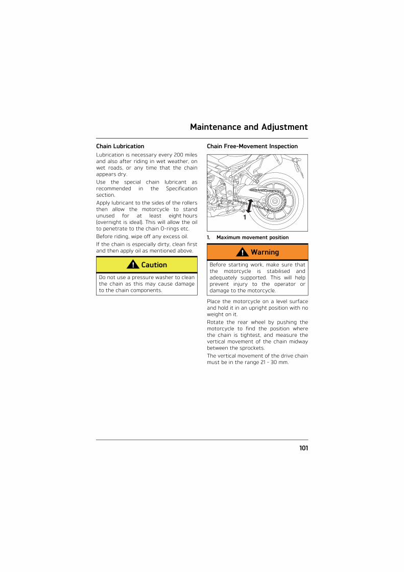
Maintenance and Adjustment
101
Chain LubricationLubrication is necessary every 200 milesand also after riding in wet weather, onwet roads, or any time that the chainappears dry.Use the special chain lubricant asrecommended in the Specificationsection.Apply lubricant to the sides of the rollersthen allow the motorcycle to standunused for at least eight hours(overnight is ideal). This will allow the oilto penetrate to the chain O-rings etc.Before riding, wipe off any excess oil.If the chain is especially dirty, clean firstand then apply oil as mentioned above.
Chain Free-Movement Inspection
1. Maximum movement position
Place the motorcycle on a level surfaceand hold it in an upright position with noweight on it.Rotate the rear wheel by pushing themotorcycle to find the position wherethe chain is tightest, and measure thevertical movement of the chain midwaybetween the sprockets.The vertical movement of the drive chainmust be in the range 21 - 30 mm.
Caution
Do not use a pressure washer to cleanthe chain as this may cause damageto the chain components.
Warning
Before starting work, make sure thatthe motorcycle is stabilised andadequately supported. This will helpprevent injury to the operator ordamage to the motorcycle.
1

Maintenance and Adjustment
102
Chain Free-Movement Adjustment
1. Adjuster clamp bolt2. C-spanner3. Eccentric adjuster
Loosen the adjuster clamp bolt.Using the C-spanner supplied in the toolkit, turn the rear hub/eccentric adjuster(clockwise to loosen, anti-clockwise totighten) until the drive chain is correctlyadjusted.Tighten the clamp bolt to 55 Nm.Repeat the chain adjustment check.Re-adjust if necessary.
Check the rear brake effectiveness.Rectify if necessary.1
23
jabb
Warning
Operation of the motorcycle with aninsecure rear hub/eccentric adjusterclamp bolt may result in impairedstability and handling of themotorcycle. This impaired stability andhandling may lead to loss of control oran accident.
Warning
It is dangerous to operate themotorcycle with defective brakes; youmust have your authorised Triumphdealer take remedial action before youattempt to ride the motorcycle again.Failure to take remedial action mayreduce braking efficiency leading toloss of control or an accident.

Maintenance and Adjustment
103
Chain and Sprocket Wear Inspection
1. Measure across 20 links2. Weight
Stretch the chain taut by hanging a10 - 20 kg weight on the chain.Measure the length of 20 links on thestraight part of the chain from pincentre of the 1st pin to the pin centre ofthe 21st pin. Since the chain may wearunevenly, take measurements in severalplaces.If the length exceeds the maximumservice limit of 320 mm, the chain mustbe replaced.Rotate the rear wheel and inspect thedrive chain for damaged rollers, andloose pins and links.
Also inspect the sprockets for unevenlyor excessively worn or damaged teeth.
If there is any irregularity, have the drivechain and/or the sprockets replaced byan authorised Triumph dealer.
2
1
Warning
Never neglect chain maintenance andalways have chains installed by anauthorised Triumph dealer.Use a genuine Triumph supplied chainas specified in the Triumph partscatalogue. The use of non-approved chains mayresult in a broken chain or may causethe chain to jump off the sprocketsleading to loss of motorcycle controlor an accident.
Caution
If the sprockets are found to be worn,always replace the sprockets anddrive chain together. Replacing wornsprockets without also replacing thechain will lead to premature wear ofthe new sprockets.
WORN TOOTH(ENGINE SPROCKET)
WORN TOOTH(REAR SPROCKET)
(Sprocket wear exaggeratedfor illustrative purposes)
ccol

Maintenance and Adjustment
104
Brakes
Brake Wear Inspection
1. Brake caliper, Speed Triple S shown2. Brake pads
Brake pads must be inspected inaccordance with scheduled maintenancerequirements and replaced if worn to, orbeyond the minimum service thickness.If the lining thickness of any pad is lessthan, 1.0 mm (0.04 in) (front) or 1.5 mm(0.06 in) (rear), replace all the pads onthe wheel.
Brake pads for this model supplied byTriumph will have the carrier plate atleast 4.5 mm thick. Always havereplacement brake pads supplied andfitted by your Triumph dealer.
1. Carrier plate, Speed Triple S shown2. Brake pad
Breaking-in New Brake Pads and DiscsNew brake discs and pads require aperiod of careful breaking-in that willoptimise the performance and longevityof the discs and pads. The recommendeddistance for breaking-in new pads anddiscs is 200 miles (300 km).During this period, avoid extremebraking, ride with caution and allow forgreater braking distances.
Warning
If fitting new proprietary brand brakepads, check that the carrier plate ofthe brake pad is at least 4.5 mm thick.Fitting brake pads with the carrierplate less than 4.5 mm thick mayresult in brake failure due to thepossible loss of the brake pad as itwears.
chay
1 2
1 2
chbe_1
4.5 mm

Maintenance and Adjustment
105
Brake Pad Wear CompensationDisc and brake pad wear is automaticallycompensated for and has no effect onthe brake lever or pedal action. Thereare no parts that require adjustment onthe front and rear brakes.
Disc Brake FluidInspect the level of brake fluid in bothreservoirs and change the brake fluid inaccordance with scheduled maintenancerequirements. Use only DOT 4 fluid asrecommended in the Specificationsection. The brake fluid must also bechanged if it becomes, or is suspected ofhaving become contaminated withmoisture or any other contaminants.
Warning
Brake pads must always be replacedas a wheel set. At the front, where twocalipers are fitted on the same wheel,replace all the brake pads in bothcalipers.Replacing individual pads will reducebraking efficiency and may cause anaccident.After replacement brake pads havebeen fitted, ride with extreme cautionuntil the new pads have 'broken in'.
Warning
If the brake lever or pedal feels softwhen it is applied, or if the lever/pedaltravel becomes excessive, there maybe air in the brake pipes and hoses orthe brakes may be defective.It is dangerous to operate themotorcycle under such conditions andyour authorised Triumph dealer mustrectify the fault before riding.Riding with defective brakes may leadto loss of motorcycle control and anaccident.
Warning
Brake fluid is hygroscopic whichmeans it will absorb moisture from theair.Any absorbed moisture will greatlyreduce the boiling point of the brakefluid causing a reduction in brakingefficiency.Because of this, always replace brakefluid in accordance with scheduledmaintenance requirements.Always use new brake fluid from asealed container and never use fluidfrom an unsealed container or fromone which has been previouslyopened.Do not mix different brands or gradesof brake fluid.Check for fluid leakage around brakefittings, seals and joints and alsocheck the brake hoses for splits,deterioration and damage.Always rectify any faults before riding.Failure to observe and act upon any ofthese items may cause a dangerousriding condition leading to loss ofcontrol and an accident.

Maintenance and Adjustment
106
Brake Fluid Level Inspection and Adjustment
1. Front brake fluid reservoir2. MAX level line3. MIN level line
The brake fluid level in the reservoirsmust be kept between the MAX and MINlevel lines (reservoir held horizontal).Remove the reservoir cover.Fill the reservoir to the upper level lineusing new DOT 4 fluid from a sealedcontainer.Refit the reservoir cover ensuring thatthe diaphragm seal is correctly fitted.Tighten the cap retaining screws to1 Nm.
1. Rear brake fluid reservoir2. Lower level line3. Upper level line
1
2
jajc_2 3
Warning
If there has been an appreciable dropin the level of the fluid in either fluidreservoir, consult your authorisedTriumph dealer for advice beforeriding. Riding with depleted brake fluid levels,or with a brake fluid leak is dangerousand will cause reduced brakeperformance potentially leading toloss of motorcycle control and anaccident.
1
3
2
cggv

Maintenance and Adjustment
107
Brake Light SwitchesThe brake light is activatedindependently by either the front or rearbrake. If, with the ignition in the ONposition, the brake light does not workwhen the front brake lever is pulled orthe rear brake pedal is pressed, haveyour authorised Triumph dealerinvestigate and rectify the fault.
Mirrors
Warning
Riding the motorcycle with defectivebrake lights is illegal and dangerous.An accident causing injury to the riderand other road users may result fromuse of a motorcycle with defectivebrake lights.
Warning
Operation of the motorcycle withincorrectly adjusted mirrors isdangerous. Operation of the motorcycle withincorrectly adjusted mirrors will resultin loss of vision to the rear of themotorcycle. It is dangerous to ride amotorcycle without sufficientrearward vision. Always adjust the mirrors to providesufficient rearward vision beforeriding the motorcycle.
Warning
Never attempt to clean or adjustmirrors while riding the motorcycle.Removal of the rider’s hands from thehandlebars while riding the motorcyclewill diminish the ability of the rider tomaintain control of the motorcycle. Attempting to clean or adjust mirrorswhile riding the motorcycle may resultin loss of control of the motorcycleand an accident. Only attempt to clean or adjust themirrors while stationary.

Maintenance and Adjustment
108
The bar end mirrors will be set by yourdealer and will not normally require anyadjustment. Should adjustment benecessary, do not rotate the mirrorbeyond 75°, measured from the verticalsection of the mirror arm.
1. Mirror arm vertical section
Warning
Incorrect adjustment of the bar endmirrors may cause the mirror arm tomake contact with the fuel tank, brakeor clutch levers or other parts of themotorcycle. This will result in damage to the fueltank, screen or other parts of themotorcycle, or restrict steeringmovement resulting in loss ofmotorcycle control and an accident. Adjust the mirrors as required toensure they do not contact any partof the motorcycle. After adjustment,move the handlebar to the left andright full lock while checking that themirrors do not contact the fuel tank,brake or clutch levers or other partsof the motorcycle.
Caution
Incorrect adjustment of the bar endmirrors may cause the mirror arm tomake contact with the fuel tank, brakeor clutch levers or other parts of themotorcycle. This will result in damage to the fueltank, brake or clutch levers or otherparts of the motorcycle.Adjust the mirrors as required toensure they do not contact any partof the motorcycle. After adjustment,move the handlebar to the left andright full lock while checking that themirrors do not contact the fuel tank,brake or clutch levers or other partsof the motorcycle.
75°
1

Maintenance and Adjustment
109
Steering/Wheel Bearings
Steering InspectionLubricate and inspect the condition ofthe steering (headstock) bearings inaccordance with scheduled maintenancerequirements.
Note:
• Always inspect the wheel bearingsat the same time as the steeringbearings.
Inspecting the Steering (Headstock) Bearings for Free Play
Inspecting the Steering for Free Play
Position the motorcycle on level ground,in an upright position.Raise the front wheel above the groundand support the motorcycle.Standing at the front of the motorcycle,hold the lower end of the front forks andtry to move them forwards andbackwards.If any free play can be detected in thesteering (headstock) bearings, ask yourauthorised Triumph dealer to inspectand rectify any faults before riding.
Remove the support and place themotorcycle on the side stand.
Warning
To prevent risk of injury from themotorcycle falling during theinspection, make sure that themotorcycle is stabilised and securedon a suitable support. Do not exertextreme force against each wheel orrock each wheel vigorously as thismay cause the motorcycle to becomeunstable and cause injury by fallingfrom its support.Make sure that the position of thesupport block will not cause damageto the sump.
Warning
Riding the motorcycle with incorrectlyadjusted or defective steering(headstock) bearings is dangerous andmay cause loss of motorcycle controland an accident.

Maintenance and Adjustment
110
Wheel Bearings InspectionIf the wheel bearings in the front or rearwheel allow play in the wheel hub, arenoisy, or if the wheel does not turnsmoothly, have your authorised Triumphdealer inspect the wheel bearings.The wheel bearings must be inspectedat the intervals specified in thescheduled maintenance chart.Position the motorcycle on level ground,in an upright position.Raise the front wheel above the groundand support the motorcycle.Standing at the side of the motorcycle,gently rock the top of the front wheelfrom side to side.If any free play can be detected, askyour authorised Triumph dealer toinspect and rectify any faults beforeriding.Reposition the lifting device and repeatthe procedure for the rear wheel.
Remove the support and place themotorcycle on the side stand.
Front Suspension
Front Fork InspectionExamine each fork for any sign ofdamage, scratching of the slider surface,or for oil leaks.If any damage or leakage is found,consult an authorised Triumph dealer.To check that the forks operatesmoothly:• Position the motorcycle on level
ground.• While holding the handlebars and
applying the front brake, pump theforks up and down several times.
• If roughness or excessive stiffness isdetected, consult your authorisedTriumph dealer.
Note:
• The suspension movement will beaffected by adjustment settings.
Warning
Operation with worn or damaged frontor rear wheel bearings is dangerousand may cause impaired handling andinstability leading to an accident. If indoubt, have the motorcycle inspectedby an authorised Triumph dealerbefore riding.
Warning
Riding the motorcycle with defectiveor damaged suspension is dangerousand may lead to loss of control and anaccident.
Warning
Never attempt to dismantle any partof the suspension units, as all unitscontain pressurised oil. Skin and eyedamage can result from contact withthe pressurised oil.

Maintenance and Adjustment
111
Suspension Setting Chart - Speed Triple S
Suspension Setting Chart - Speed Triple R
Note:
• Both the Speed Triple S and SpeedTriple R motorcycles are deliveredfrom the factory with thesuspension set at the Road ridingsettings, as shown in the relevantsuspension chart.
• These charts are only a guide.Setting requirements may vary forrider weight and personalpreferences. See the following pagesfor information regarding suspensionadjustment.
LOADING FRONT REAR
Spring Pre-Load¹
Rebound Damping¹
Compression Damping¹
Rebound Damping¹
Compression Damping¹
Solo Riding Road 7.5 2.5 2 2.5 2
Comfort 7.5 2.75² 3² 2.75² 3²
Track 7.5 1 0.5 0.75 0.5
Sport 7.5 1.5 1.5 1.5 1.5
Rider and Passenger 7.5 1.5 1.5 1 1
¹ Number of adjuster turns anti-clockwise from the fully clockwise position.² Number of maximum adjuster turns unless already fully screwed out.
LOADING FRONT REAR
Spring Pre-Load¹
Rebound Damping²
Compression Damping²
Rebound Damping²
Compression Damping²
Solo Riding Road 8.5 16 19 16 19
Comfort 8.5 16 26 16 fully anti-clockwise
Track 8.5 9 9 7 7
Sport 8.5 11 16 11 18
Rider and Passenger 8.5 10 12 8 15
¹ Number of adjuster turns clockwise from the fully anti-clockwise position.² Number of clicks anti-clockwise from the fully clockwise position noting that the first stop (click) is counted as one.

Maintenance and Adjustment
112
The standard suspension settingsprovide a comfortable ride and goodhandling characteristics for general, soloriding. The chart shows suggestedsettings for the front and rearsuspension.
Front Suspension Adjustment
Spring Pre-Load Adjustment
1. Speed Triple S spring pre-load adjuster
1. Speed Triple R spring pre-load adjuster
The spring pre-load adjusters arelocated at the top of each fork.
Warning
Make sure that the correct balancebetween front and rear suspension ismaintained. Suspension imbalancecould significantly change handlingcharacteristics leading to loss ofcontrol and an accident. Refer to thechart on page 111 for furtherinformation or consult your dealer.
Warning
Make sure that the adjusters are setto the same setting on both forks.Settings which vary from left to rightcould significantly change handlingcharacteristics leading to loss ofcontrol and an accident.
1
cgfj_1
1
chcy

Maintenance and Adjustment
113
To change the spring pre-load, rotatethe adjuster clockwise to increasepre-load, or anti-clockwise to decreasepre-load. Always count the number ofclockwise turns from the fully anti-clockwise position and set both forks tothe same settings.
Note:
• The Speed Triple S is delivered fromthe factory with the spring pre-loadset at 7.5 clockwise turns from thefully anti-clockwise position.
• The Speed Triple R is delivered fromthe factory with the spring pre-loadset at 8.5 clockwise turns from thefully anti-clockwise position.
Rebound Damping Adjustment - Speed Triple S
1. Rebound damping adjusterThe rebound damping adjuster is locatedat the top of each forkTo change the rebound damping force,rotate the slotted adjuster clockwise toincrease, or anti-clockwise to decrease.Always count the number of anti-clockwise turns from the fully clockwiseposition and set both forks to the samesettings.
Note:
• The motorcycle is delivered from thefactory with the rebound set at2.5 anti-clockwise turns from thefully clockwise position.
1
cgfj_2

Maintenance and Adjustment
114
Rebound Damping Adjustment - Speed Triple R
1. Rebound damping adjusterThe rebound damping adjuster is locatedat the top of the right hand fork.To change the rebound damping force,rotate the adjuster clockwise toincrease, or anti-clockwise to decreaseusing a 3 mm Allen key. Always count the number of clicks fromthe fully clockwise position noting thatthe first stop (click position) is countedas zero.
Note:
• The motorcycle is delivered from thefactory with the rebound set at16 clicks from the fully clockwiseposition.
Compression Damping Adjustment -Speed Triple S
1. Compression damping adjusterThe compression damping adjuster islocated near the bottom of both forks,adjacent to the wheel spindle.To change the compression dampingforce, rotate the slotted adjusterclockwise to increase, or anti-clockwiseto decrease. Always count the number of anti-clockwise turns from the fully clockwiseposition and set both forks to the samesettings.
Note:
• The motorcycle is delivered from thefactory with the compressiondamping set at 2 anti-clockwiseturns from the fully clockwiseposition.
1
chcy_1
1
cgfi
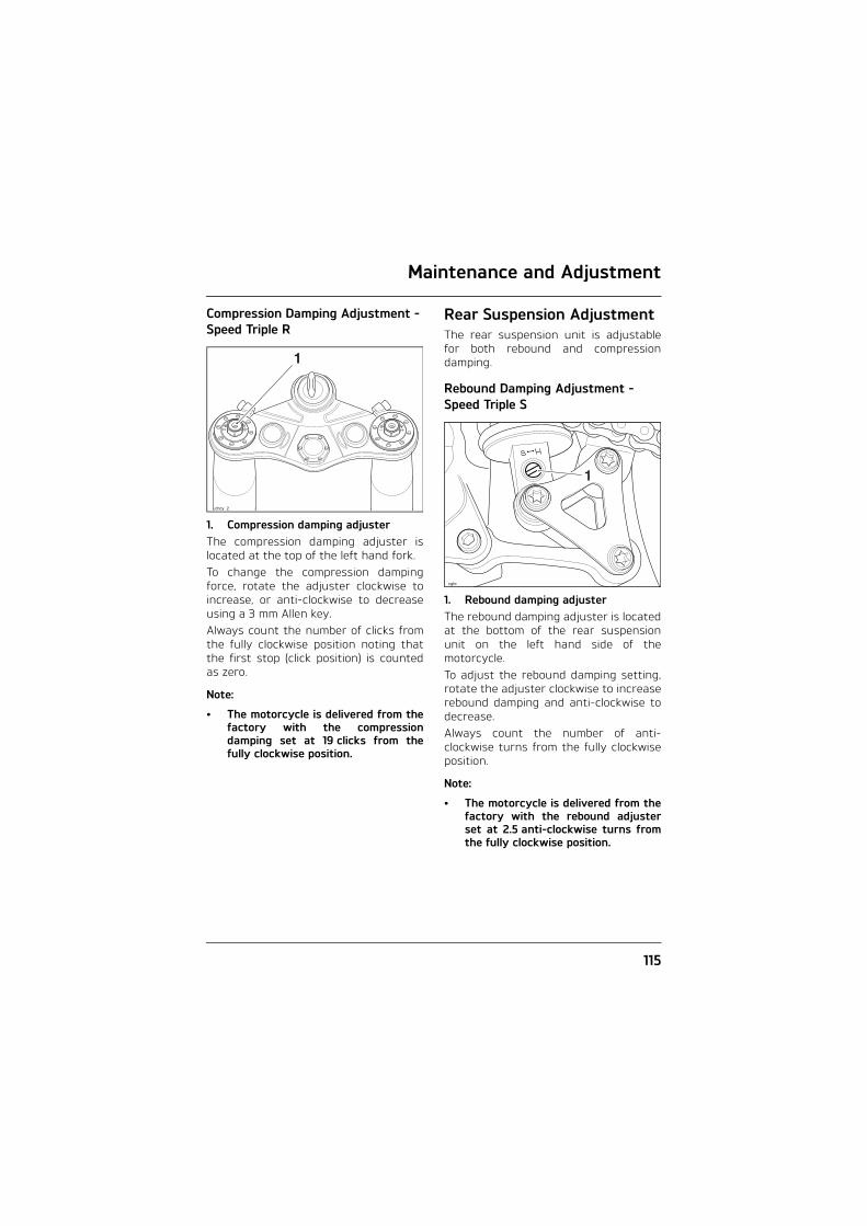
Maintenance and Adjustment
115
Compression Damping Adjustment - Speed Triple R
1. Compression damping adjusterThe compression damping adjuster islocated at the top of the left hand fork.To change the compression dampingforce, rotate the adjuster clockwise toincrease, or anti-clockwise to decreaseusing a 3 mm Allen key. Always count the number of clicks fromthe fully clockwise position noting thatthe first stop (click position) is countedas zero.
Note:
• The motorcycle is delivered from thefactory with the compressiondamping set at 19 clicks from thefully clockwise position.
Rear Suspension AdjustmentThe rear suspension unit is adjustablefor both rebound and compressiondamping.
Rebound Damping Adjustment - Speed Triple S
1. Rebound damping adjusterThe rebound damping adjuster is locatedat the bottom of the rear suspensionunit on the left hand side of themotorcycle.To adjust the rebound damping setting,rotate the adjuster clockwise to increaserebound damping and anti-clockwise todecrease. Always count the number of anti-clockwise turns from the fully clockwiseposition.
Note:
• The motorcycle is delivered from thefactory with the rebound adjusterset at 2.5 anti-clockwise turns fromthe fully clockwise position.
1
chcy_2
1
cgfe

Maintenance and Adjustment
116
Rebound Damping Adjustment - Speed Triple R
1. Rebound damping adjusterThe rebound damping adjuster isaccessible from the left hand side of themotorcycle. It is coloured black and issituated close to the rear suspensionreservoir.To adjust the rebound damping setting,rotate the adjuster clockwise to increaserebound damping and anti-clockwise todecrease. Always count the number of clicks anti-clockwise from the fully clockwiseposition noting that the first stop (clickposition) is counted as zero.
Note:
• The motorcycle is delivered from thefactory with the rebound adjusterset at 16 clicks from the fullyclockwise position.
Compression Damping Adjustment - Speed Triple S
1. Compression damping adjusterThe compression damping adjuster issituated below the rear suspension unitreservoir.To adjust the compression dampingsetting, rotate the slotted adjusterclockwise to increase, or anti-clockwiseto decrease. Always count the number of anti-clockwise turns from the fully clockwiseposition.
Note:
• The motorcycle is delivered from thefactory with the compressiondamping set at 2 anti-clockwiseturns from the fully clockwiseposition.
1
chcx
1
cgfb
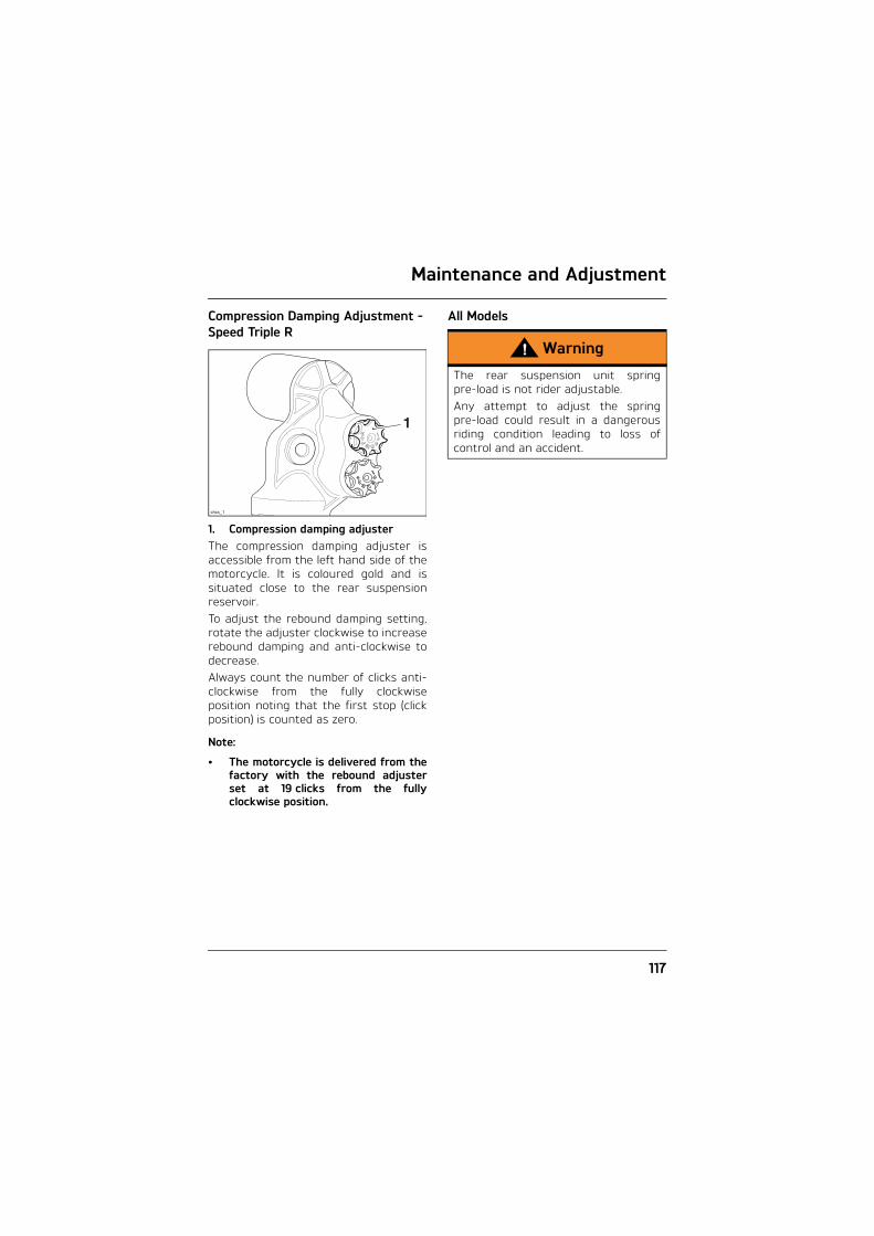
Maintenance and Adjustment
117
Compression Damping Adjustment - Speed Triple R
1. Compression damping adjusterThe compression damping adjuster isaccessible from the left hand side of themotorcycle. It is coloured gold and issituated close to the rear suspensionreservoir.To adjust the rebound damping setting,rotate the adjuster clockwise to increaserebound damping and anti-clockwise todecrease. Always count the number of clicks anti-clockwise from the fully clockwiseposition noting that the first stop (clickposition) is counted as zero.
Note:
• The motorcycle is delivered from thefactory with the rebound adjusterset at 19 clicks from the fullyclockwise position.
All Models
1
chcx_1
Warning
The rear suspension unit springpre-load is not rider adjustable. Any attempt to adjust the springpre-load could result in a dangerousriding condition leading to loss ofcontrol and an accident.

Maintenance and Adjustment
118
Tyres
Typical Tyre Marking
This motorcycle is equipped withtubeless tyres, valves and wheel rims.Use only tyres marked 'TUBELESS' andtubeless valves on rims marked'TUBELESS'.
Wheel Marking
Tyre Inflation PressuresCorrect inflation pressure will providemaximum stability, rider comfort andtyre life. Always check tyre pressuresbefore riding when the tyres are cold.Check tyre pressures daily and adjust ifnecessary. See the Specification sectionfor details of the correct inflationpressures.
Tyre Pressure Monitoring System (if fitted)The tyre pressures shown on yourinstrument pack indicate the actual tyrepressure at the time of selecting thedisplay. This may differ from the inflationpressure set when the tyres are coldbecause tyres become warmer duringriding, causing the air in the tyre toexpand and increase the inflationpressure. The cold inflation pressuresspecified by Triumph take account ofthis.Owners must only adjust tyre pressureswhen the tyres are cold using anaccurate pressure gauge, and must notuse the tyre pressure display on theinstruments.
TUBELESS
Warning
Incorrect tyre inflation will causeabnormal tread wear and instabilityproblems that may lead to loss ofcontrol and an accident.Under-inflation may result in the tyreslipping on, or coming off the rim.Over-inflation will cause instability andaccelerated tread wear.Both conditions are dangerous asthey may cause loss of control leadingto an accident.

Maintenance and Adjustment
119
Tyre WearAs the tyre tread wears down, the tyrebecomes more susceptible to puncturesand failure. It is therefore notrecommended to use tyres until they areworn to their minimum.
Minimum Recommended Tread DepthIn accordance with the periodicmaintenance chart, measure the depthof the tread with a depth gauge, andreplace any tyre that has worn to, orbeyond the minimum allowable treaddepth specified in the table below:
Under 130 km/h (80 mph)
2 mm (0.08 in)
Over 130 km/h (80 mph)
Rear 3 mm (0.12 in)Front 2 mm (0.08 in)
Warning
Only operate this Triumph motorcycleat high speed in closed-courseon-road competition or on closed-course racetracks. High-speedoperation should only then beattempted by riders who have beeninstructed in the techniquesnecessary for high-speed riding andare familiar with the motorcycle'scharacteristics in all conditions. High-speed operation in any othercircumstances is dangerous and willlead to loss of motorcycle control andan accident.
Warning
This motorcycle must not be operatedabove the legal road speed limitexcept in authorised closed-courseconditions.
Warning
Operation with excessively worn tyresis hazardous and will adversely affecttraction, stability and handling whichmay lead to loss of control and anaccident.When tubeless tyres becomepunctured, leakage is often very slow.Always inspect tyres very closely forpunctures. Check the tyres for cuts,embedded nails or other sharpobjects. Operation with punctured ordamaged tyres will adversely affectmotorcycle stability and handlingwhich may lead to loss of control or anaccident.Check the rims for dents ordeformation. Operation with damagedor defective wheels or tyres isdangerous and loss of motorcyclecontrol or an accident could result.Always consult your authorisedTriumph dealer for tyre replacement,or for a safety inspection of the tyres.

Maintenance and Adjustment
120
Tyre ReplacementAll Triumph motorcycles are carefullyand extensively tested in a range ofriding conditions to ensure that themost effective tyre combinations areapproved for use on this model. It isessential that approved tyres, fitted inapproved combinations, are used whenpurchasing replacement tyres. The use of non-approved tyres, orapproved tyres in non-approvedcombinations, may lead to motorcycleinstability and an accident. On modelsfitted with ABS, different wheel speeds,caused by non-approved tyres canaffect the function of the ABS computer.See the Specification section for detailsof approved tyre combinations. Alwayshave tyres fitted and balanced by yourauthorised Triumph dealer who has thenecessary training and skills to ensuresafe, effective fitment.
Tyre Pressure Monitoring System(Only on models fitted with TPMS)
Caution
An adhesive label is fitted to the wheelrim to indicate the position of the tyrepressure sensor. Care must be takenwhen replacing the tyres to preventany damage to the tyre pressuresensors. Always have your tyres fittedby your authorised Triumph dealerand inform them that tyre pressuresensors are fitted to the wheels.
Warning
Use of non-recommended tyres canaffect wheel speed and cause theTriumph traction control function notto operate, potentially leading to lossof control and an accident inconditions where the Triumph tractioncontrol would normally function.
Warning
On models fitted with ABS, the ABScomputer operates by comparing therelative speed of the front and rearwheels. Use of non-recommendedtyres can affect wheel speed andcause the ABS function not tooperate, potentially leading to loss ofcontrol and an accident in conditionswhere the ABS would normallyfunction.

Maintenance and Adjustment
121
Warning
If a tyre sustains a puncture, the tyremust be replaced. Failure to replace apunctured tyre, or operation with arepaired tyre can lead to instability,loss of control or an accident.
Warning
Do not install tube-type tyres ontubeless rims. The bead will not seatand the tyres could slip on the rims,causing rapid tyre deflation that mayresult in a loss of vehicle control andan accident. Never install an innertube inside a tubeless tyre. This willcause friction inside the tyre and theresulting heat build-up may cause thetube to burst resulting in rapid tyredeflation, loss of vehicle control andan accident.
Warning
If tyre damage is suspected, such asafter striking the kerb, ask yourauthorised Triumph dealer to inspectthe tyre both internally andexternally. Remember, tyre damagemay not always be visible from theoutside. Operation of the motorcyclewith damaged tyres could lead to lossof control and an accident.
Warning
When replacement tyres are required,consult your authorised Triumphdealer who will arrange for the tyresto be selected, in a correctcombination, from the approved listand fitted according to the tyremanufacturer's instructions.When tyres are replaced, allow timefor the tyres to seat to the rim(approximately 24 hours). During thisseating period, ride cautiously as anincorrectly seated tyre could causeloss of control or an accident.Initially, the new tyres will not producethe same handling characteristics asthe worn tyres and the rider mustallow adequate riding distance(approximately 100 miles) to becomeaccustomed to the new handlingcharacteristics.24 hours after fitting, the tyrepressures must be checked andadjusted, and the tyres examined forcorrect seating. Rectification must becarried out as necessary.The same checks and adjustmentsmust also be carried out when100 miles have been travelled afterfitting.
Warning
Use of a motorcycle with incorrectlyseated tyres, incorrectly adjusted tyrepressures, or when not accustomed toits handling characteristics may leadto loss of control and an accident.

Maintenance and Adjustment
122
BatteryWarning
Tyres that have been used on a rollingroad dynamometer may becomedamaged. In some cases, the damagemay not be visible on the externalsurface of the tyre. Tyres must bereplaced after such use as continueduse of a damaged tyre may lead toinstability, loss of control and anaccident.
Warning
Accurate wheel balance is necessaryfor safe, stable handling of themotorcycle. Do not remove or changeany wheel balance weights. Incorrectwheel balance may cause instabilityleading to loss of control and anaccident.When wheel balancing is required,such as after tyre replacement, seeyour authorised Triumph dealer.Only use self-adhesive weights. Clip-on weights may damage the wheeland tyre resulting in tyre deflation,loss of control and an accident.
Warning
Under some circumstances, thebattery can give off explosive gases;keep sparks, flames and cigarettesaway. Provide adequate ventilationwhen charging or using the battery inan enclosed space.The battery contains sulphuric acid(battery acid). Contact with skin oreyes may cause severe burns. Wearprotective clothing and a face shield.If battery acid gets on your skin, flushwith water immediately.If battery acid gets in your eyes, flushwith water for at least 15 minutes andSEEK MEDICAL ATTENTIONIMMEDIATELY.If battery acid is swallowed, drink largequantities of water and SEEK MEDICALATTENTION IMMEDIATELY.KEEP BATTERY ACID OUT OF THEREACH OF CHILDREN.
Warning
The battery contains harmfulmaterials. Always keep children awayfrom the battery whether or not it isfitted in the motorcycle.Do not attach jump leads to thebattery, touch the battery cablestogether or reverse the polarity of thecables as any of these actions maycause a spark which would ignitebattery gases causing a risk ofpersonal injury.

Maintenance and Adjustment
123
Battery RemovalRaise and support the fuel tank (seepage 97).
1. Battery2. Battery strap3. Negative (black) terminal4. Positive (red) terminal
Remove the battery strap.Disconnect the battery leads, negative(black) lead first.Take the battery out of the case.
Battery DisposalShould the battery ever requirereplacement, the original battery mustbe handed to a recycling agent who willmake sure that the dangeroussubstances from which the battery ismanufactured do not pollute theenvironment.
Battery MaintenanceClean the battery using a clean, drycloth. Be sure that the cableconnections are clean.
The battery is a sealed type and doesnot require any maintenance other thanchecking the Voltage and routinerecharging when required, such asduring storage.It is not possible to adjust the batteryacid level in the battery; the sealing stripmust not be removed.
Warning
Make sure that the battery terminalsdo not touch the motorcycle frame asthis may cause a short circuit orspark, which would ignite batterygases causing a risk of personalinjury.
2
cgfg
1
3 4
Warning
The battery acid is corrosive andpoisonous and will cause damage tounprotected skin. Never swallowbattery acid or allow it to come intocontact with the skin. To preventinjury, always wear eye and skinprotection when handling the battery.

Maintenance and Adjustment
124
Battery Discharge
Under normal conditions, the motorcyclecharging system will keep the batteryfully charged. However, if the motorcycleis unused, the battery will graduallydischarge due to a normal process calledself discharge; the clock, Engine ControlModule (ECM) memory, high ambienttemperatures, or the addition ofelectrical security systems or otherelectrical accessories will all increasethis rate of battery discharge.Disconnecting the battery from themotorcycle during storage will reducethe rate of discharge.
Battery Discharge During Storage and Infrequent Use of the MotorcycleDuring storage or infrequent use of themotorcycle, inspect the battery Voltageweekly using a digital multimeter. Followthe manufacturer's instructions suppliedwith the meter. Should the battery Voltage fall below12.7 Volts, the battery should be charged(see page 125).Allowing a battery to discharge orleaving it discharged for even a shortperiod of time causes sulphation of thelead plates. Sulphation is a normal partof the chemical reaction inside thebattery, however over time the sulphatecan crystallise on the plates makingrecovery difficult or impossible. Thispermanent damage is not covered bythe motorcycle warranty, as it is not dueto a manufacturing defect.Keeping the battery fully chargedreduces the likelihood of it freezing incold conditions. Allowing a battery tofreeze will cause serious internaldamage to the battery.
Caution
The charge level in the battery mustbe maintained to maximise battery life.Failure to maintain the battery chargelevel could cause serious internaldamage to the battery.

Maintenance and Adjustment
125
Battery ChargingFor help with selecting a batterycharger, checking the battery Voltage orbattery charging, contact your localauthorised Triumph dealer.
Should the battery Voltage fall below12.7 Volts, the battery should be chargedusing a Triumph approved batterycharger. Always follow the instructionssupplied with the battery charger.For extended periods of storage (beyondtwo weeks) the battery should beremoved from the motorcycle and keptcharged using a Triumph approvedmaintenance charger.Similarly, should the battery charge fallto a level where it will not start themotorcycle, remove the battery from themotorcycle before charging.
Battery Installation
Place the battery in the battery case.Reconnect the battery, positive (red)lead first.Apply a light coat of grease to theterminals to prevent corrosion.Cover the positive terminal with theprotective cap.Refit the battery strap.Lower and secure the fuel tank (seepage 98).
Warning
The battery gives off explosive gases;keep sparks, flames and cigarettesaway. Provide adequate ventilationwhen charging or using the battery inan enclosed space.The battery contains sulphuric acid(battery acid). Contact with skin oreyes may cause severe burns. Wearprotective clothing and a face shield.If battery acid gets on your skin, flushwith water immediately.If battery acid gets in your eyes, flushwith water for at least 15 minutes andSEEK MEDICAL ATTENTIONIMMEDIATELY.If battery acid is swallowed, drink largequantities of water and SEEK MEDICALATTENTION IMMEDIATELY.KEEP BATTERY ACID OUT OF THEREACH OF CHILDREN.
Caution
Do not use an automotive quickcharger as it may overcharge anddamage the battery.
Warning
Make sure that the battery terminalsdo not touch the motorcycle frame asthis may cause a short circuit orspark, which would ignite batterygases causing a risk of personalinjury.

Maintenance and Adjustment
126
Fuse Boxes
1. Front fuse box2. Rear fuse boxThe two fuse boxes are located underthe seat.
Fuse IdentificationA blown fuse is indicated when all of thesystems protected by that fuse becomeinoperative. When checking for a blownfuse, use the tables to establish whichfuse has blown.The fuse identification numbers listed inthe tables correspond with those printedon the fuse box cover, as shown. Sparefuses are located at right angles to themain fuses and should be replaced ifused.
Front Fuse Box
1. Fuse box2. Fuse box cover
Warning
Always replace blown fuses with newones of the correct rating (as specifiedon the fuse box cover) and never usea fuse of higher rating. Use of anincorrect fuse could lead to anelectrical problem, resulting inmotorcycle damage, loss of motorcyclecontrol and an accident.
L0041
12
Position Circuits Protected Rating (Amps)
1 Dipped and high beam headlights
20
2 Engine ECM 20
3 Alarm, instrument lights 5
4 Cooling fan 15
5 Fuel pump 10
6 Ignition switch 10
7 Horn, direction indicators, Daytime Running Lights (DRL) if fitted
10
8 Rear light, license plate light
5
9 Heated grips (if fitted) 5
2
1
123456
789

Maintenance and Adjustment
127
Rear Fuse Box
1. Fuse box2. Fuse box cover3. Spare fuse
Main FuseThe 30 Amp main fuse is located in frontof the battery. To allow access to thisfuse, the front panel on the fuel tankmust be removed.
1. Main fuse2. Battery
Position Circuits Protected Rating (Amps)
1 Accessories 5
2 ABS 25
3 Spare 20
SPARE2 13
2
1
3
SPARE ABS ACC5A25A20A
2
cgfg_1
1

Maintenance and Adjustment
128
Headlights
Warning
Adjust road speed to suit the visibilityand weather conditions in which themotorcycle is being operated.Make sure that the beams areadjusted to illuminate the roadsurface sufficiently far ahead withoutdazzling oncoming traffic. Anincorrectly adjusted headlight mayimpair visibility causing an accident.
Warning
Never attempt to adjust a headlampbeam when the motorcycle is inmotion.Any attempt to adjust a headlampbeam when the motorcycle is inmotion may result in loss of controland an accident.
Caution
If the motorcycle is to be used underclosed-course conditions, you may beasked to tape the visible outer surfaceof the headlightWhen taped, the headlight willoverheat and distort the outersurface. Therefore, to avoid headlightdistortion, always disconnect theheadlights when they are taped foruse under closed-course conditions.
Caution
Do not cover the headlight or lenswith any item likely to obstruct airflow to, or prevent heat escaping from,the headlight lens.Covering the headlight lens duringoperation with items of clothing,luggage, adhesive tape, devicesintended to alter or adjust theheadlight beam or non genuineheadlight lens covers will cause theheadlight lens to overheat and distort,causing irreparable damage to theheadlight assembly.Damage caused by overheating is notconsidered a manufacturing defectand will not be covered underwarranty. If the headlight must be coveredduring use, such as the taping of theheadlight lens required during closed-course conditions, the headlight mustbe disconnected.

Maintenance and Adjustment
129
Headlight Adjustment - Vertical
1. Bolts2. Front subframe alignment marks3. Headlight bracket
The vertical beams of the left and righthand headlights can only be adjustedtogether. Independent adjustment is notpossible.Switch the headlight dipped beam on.Slacken the two bolts securing theheadlight bracket to the front subframesufficiently to allow restricted movementof the headlights.Using the headlight bracket mark andthe alignment markings on the frontsubframe, adjust the position of theheadlights to give the required beamsetting. Each mark on the subframerepresents 1°. Moving the bracket forwards moves theheadlight downwards. Moving thebracket rearwards moves the headlightsupwards.Tighten the headlight bracket bolts to7 Nm. Recheck the headlight beam settings.Switch the headlights off when the beamsettings are satisfactorily set.
Headlight Bulb Replacement
Release the three fixings and removethe front panel from the fuel tank.
1. Front panel2. Fixings
Disconnect the battery, negative (black)lead first.
L0037
12
3
Warning
The bulbs become hot during use.Always allow sufficient time for thebulbs to cool before handling. Avoid touching the glass part of thebulb. If the glass is touched or getsdirty, clean with alcohol before re-use.
Caution
The use of non-approved headlightbulbs may result in damage to theheadlight lens.Use a genuine Triumph suppliedheadlight bulb as specified in theTriumph Parts Catalogue.Always have replacement headlightbulbs installed by an authorisedTriumph dealer.
cgfo
21
2 2

Maintenance and Adjustment
130
Unscrew the headlight bulb cover fromthe rear of the headlight assembly andremove with the gasket.
1. Headlight assembly2. Headlight bulb cover
Disconnect the multi-pin connector fromthe headlight bulb.
1. Headlight assembly2. Headlight bulb3. Multi-pin connector
Detach the wire retainer from its clip (donot remove the screw) then remove thebulb from the light unit.
1. Wire retainer2. Screw3. Headlight bulb
Installation is the reverse of the removalprocedure.
Reconnect the battery, positive (red)lead first.Refit the front panel and tighten thefixings to 2 Nm.
L0038
1
2
L0039
1
2
3
Warning
Do not reconnect the battery until theassembly process has been completed.Premature battery reconnection couldresult in ignition of the battery gasescausing risk of injury.
Caution
When reconnecting the battery,connect the positive (red) lead first.
cgfn 2
2
1
3

Maintenance and Adjustment
131
Daytime Running Lights (DRL) (if fitted)The daytime running lights are situatedwithin the headlight assembly and aresealed, maintenance free LED units.
Rear Light
Rear Light ReplacementThe rear light unit is a sealed,maintenance free LED unit.
Direction Indicator Lights
Bulb Replacement
1. Indicator lens2. Securing screw
The lens on each indicator light is held inplace by a securing screw located in thelens of the light.Release the screw and remove the lensto gain access to the bulb forreplacement.
LED Direction Indicator Lights (if fitted)The LED direction indicator light unitsare sealed, maintenance free LED units.
celc
1
2

Maintenance and Adjustment
132
License Plate Light
Bulb ReplacementRelease the three fixings and removethe front panel from the fuel tank.
1. Front panel2. Fixings
Disconnect the battery, negative (black)lead first.
1. Fixing2. License plate bracket
Release the fixing and detach the lightfrom the license plate bracket. It is notnecessary to disconnect the licenseplate electrical connectors.
Carefully remove the bulb holder fromthe back of the license plate light unit.Remove the bulb.
1. License plate light2. Bulb holder
Installation is the reverse of the removalprocedure, noting the following:Tighten the lamp fixing to 2 Nm.Reconnect the battery, positive (red)lead first.Refit the front panel and tighten theside fixings to 2 Nm.
cgfo
21
2 2
cjgn
12
Caution
To avoid cable damage, do not pull thebulb holder using the cables. Pull onlyon the bulb holder.
1
cgfk
2
Maintenance and Adjustment
133
CleaningFrequent, regular cleaning is anessential part of the maintenance ofyour motorcycle. If regularly cleaned, theappearance will be preserved for manyyears. Cleaning with cold watercontaining an automotive cleaner isessential at all times but particularly soafter exposure to sea breezes, seawater, dusty or muddy roads and inwinter when roads are treated for iceand snow. Do not use householddetergent, as the use of such productswill lead to premature corrosion.Although, under the terms of yourmotorcycle warranty, cover is providedagainst the corrosion of certain items,the owner is expected to observe thisreasonable advice which will safeguardagainst corrosion and enhance theappearance of the motorcycle.
Preparation for WashingBefore washing, precautions must betaken to keep water off the followingplaces:• Rear opening of the exhausts:
Cover with a plastic bag securedwith rubber bands.
• Clutch and brake levers, switchhousings on the handlebars: Cover with plastic bags.
• Ignition switch and steering lock: Cover the keyhole with tape.
Remove any items of jewellery such asrings, watches, zips or belt buckles,which may scratch or otherwise damagepainted or polished surfaces.Use separate cleaning sponges orcleaning cloths for washingpainted/polished surfaces and chassisareas. Chassis areas (such as wheelsand under mudguards) will be exposedto more abrasive road grime and dust,which may then scratch painted orpolished surfaces, if the same sponge orcleaning cloths are used.

Maintenance and Adjustment
134
Where to be CarefulAvoid spraying water with any greatforce near the following places:• Instruments;• Brake cylinders and brake calipers;• Under the fuel tank;• Headstock bearings;• Air intake ducts.
Note:
• Use of soaps that are highly alkalinewill leave a residue on paintedsurfaces, and may also cause waterspotting. Always use a low alkalinesoap to aid the cleaning process.
After WashingRemove the plastic bags and tape, andclear the air intakes.Lubricate the pivots, bolts and nuts.Test the brakes before motorcycleoperation.Start the engine and run it forfive minutes. Make sure there isadequate ventilation for the exhaustfumes.Use a dry cloth to absorb water residue.Do not allow water to stand on themachine as this will lead to corrosion.
Seat Care
To help maintain its appearance, cleanthe seat using a sponge or cleaningcloth with soap and water.
Caution
Do not spray any water at all underthe fuel tank. Any water sprayedaround the air intake ducts couldenter the airbox and engine, causingdamage to both items.
Caution
Use of high-pressure spray washers isnot recommended. When usingpressure washers, water may beforced into bearings and othercomponents causing premature wearfrom corrosion and loss of lubrication.
Warning
Never wax or lubricate the brake discs.Loss of braking power and an accidentcould result. Clean the disc with aproprietary brand of oil-free brakedisc cleaner.
Caution
Use of chemicals or high-pressurespray washers is not recommendedfor cleaning the seat. Using chemicalsor pressure washers may damage theseat cover.

Maintenance and Adjustment
135
Unpainted Aluminium ItemsItems such as brake and clutch levers,wheels, engine covers, top and bottomyokes on some models must be correctlycleaned to preserve their appearance.Please contact your dealer if you areunsure which components on yourmotorcycle are unpainted aluminiumparts.Use a proprietary brand of aluminiumcleaner which does not contain abrasiveor caustic elements.Clean aluminium items regularly, inparticular after use in inclementweather, where the components mustbe hand washed and dried each time themachine is used.Warranty claims due to inadequatemaintenance will not be allowed.
Cleaning of the Exhaust SystemAll parts of the exhaust system of yourmotorcycle must be cleaned regularly toavoid a deterioration of its appearance.These instructions can be applied tochrome, brushed stainless steel andcarbon fibre components alike.
Note:
• The exhaust system must be coolbefore washing to prevent waterspotting.
WashingPrepare a mixture of cold water and mildautomotive cleaner. Do not use a highlyalkaline soap as commonly found atcommercial car washes because it leavesa residue.Wash the exhaust system with a softcloth. Do not use an abrasive scouringpad or steel wool. They will damage thefinish.Rinse the exhaust system thoroughly.Make sure no soap or water enters themufflers.
DryingDry the exhaust system as far aspossible with a soft cloth. Do not run theengine to dry the system or spotting willoccur.
ProtectingWhen the exhaust system is dry, rub'Motorex 645 Clean and Protect' into thesurface.
It is recommended that regularprotection be applied to the system asthis will both protect and enhance thesystem's appearance.
Caution
The use of products containingsilicone will cause discolouration ofany chrome and must not be used.Similarly, the use of abrasive cleanersand polishes will damage the systemand must not be used.

Maintenance and Adjustment
136
This page intentionally left blank

Storage
137
STORAGE
Preparation for StorageClean and dry the entire vehiclethoroughly. Fill the fuel tank with the correct gradeof unleaded fuel and add a fuel stabiliser(if available), following the fuel stabilisermanufacturer's instructions.
Remove the spark plug from eachcylinder and put several drops (5 cc) ofengine oil into each cylinder. Cover thespark plug holes with a piece of cloth orrag. With the engine stop switch in theRUN position, push the starter buttonfor a few seconds to coat the cylinderwalls with oil. Install the spark plugs,tightening to 12 Nm. Change the engine oil and filter (seepage 92).Check and if necessary correct the tyrepressures (see page 118). Set the motorcycle on a stand so thatboth wheels are raised off the ground. (Ifthis cannot be done, put boards underthe front and rear wheels to keepdampness away from the tyres.)
Spray rust inhibiting oil (there are a hostof products on the market and yourdealer will be able to offer you localadvice) on all unpainted metal surfacesto prevent rusting. Prevent oil fromgetting on rubber parts, brake discs or inthe brake calipers. Lubricate and if necessary adjust thedrive chain (see page 101).Make sure the cooling system is filledwith a 50% mixture of coolant (notingthat HD4X Hybrid OAT coolant, assupplied by Triumph, is pre-mixed andrequires no dilution) and distilled watersolution (see page 94).Remove the battery, and store it whereit will not be exposed to direct sunlight,moisture, or freezing temperatures.During storage it should be given a slowcharge (one ampere or less) about onceevery two weeks (see page 122).Store the motorcycle in a cool, dry area,away from sunlight, and with a minimumdaily temperature variation.Put a suitable porous cover over themotorcycle to keep dust and dirt fromcollecting on it. Avoid using plastic orsimilar non-breathable, coated materialsthat restrict air flow and allow heat andmoisture to accumulate.
Warning
Petrol is extremely flammable and canbe explosive under certain conditions.Turn the ignition switch off. Do notsmoke. Make sure the area is wellventilated and free from any source offlame or sparks; this includes anyappliance with a pilot light.

Storage
138
Preparation after StorageInstall the battery (if removed) (seepage 122).If the motorcycle has been stored formore than four months, change theengine oil (see page 92).Check all the points listed in the DailySafety Checks section.Before starting the engine, remove thespark plugs from each cylinder. Refer tothe Service Manual for detailedprocedures or consult your dealer.Put the side stand down.
Crank the engine on the starter motorseveral times until the oil pressure lightgoes out.Replace the spark plugs, tightening to12 Nm, and start the engine.Check and if necessary correct the tyrepressures (see page 118).Clean the entire vehicle thoroughly.Check the brakes for correct operation.Test ride the motorcycle at low speeds.

139
Specifications
SPECIFICATIONS
Dimensions, Weights and Performance
A list of model specific dimensions, weights and performance is available from your authorised Triumph dealer, or on the Internet at www.triumph.co.uk.
Maximum Payload . . . . . . . . . . . . . . . . . . . . 198 kg
Engine
Type . . . . . . . . . . . . . . . . . . . . . . . . . . . . . . . . In-line 3 cylinder
Displacement . . . . . . . . . . . . . . . . . . . . . . . . 1,050 cc
Bore x Stroke . . . . . . . . . . . . . . . . . . . . . . . . 79 x 71.4 mm
Compression Ratio . . . . . . . . . . . . . . . . . . . 12.25:1
Cylinder Numbering . . . . . . . . . . . . . . . . . . Left to Right
Cylinder Sequence Number . . . . . . . . . . . . 1 at left
Firing Order . . . . . . . . . . . . . . . . . . . . . . . . . 1-2-3
Starting System. . . . . . . . . . . . . . . . . . . . . . Electric Starter
Lubrication
Lubrication . . . . . . . . . . . . . . . . . . . . . . . . . . Forced Lubrication (wet sump)
Engine Oil Capacities
Dry Fill . . . . . . . . . . . . . . . . . . . . . . . . . . . . . . 3.5 litres
Oil/Filter Change . . . . . . . . . . . . . . . . . . . . . 3.2 litres
Oil Change Only . . . . . . . . . . . . . . . . . . . . . . 3.0 litres

140
Specifications
Cooling
Coolant Type. . . . . . . . . . . . . . . . . . . . . . . . . Triumph HD4X Hybrid OAT coolant
Water/Anti-freeze ratio . . . . . . . . . . . . . . . 50/50 (premixed as supplied by Triumph)
Coolant Capacity . . . . . . . . . . . . . . . . . . . . . 2.4 litres
Thermostat Opens (nominal) . . . . . . . . . . . 85°C
Fuel System
Type . . . . . . . . . . . . . . . . . . . . . . . . . . . . . . . . Electronic Fuel Injection
Injectors . . . . . . . . . . . . . . . . . . . . . . . . . . . . Solenoid Operated
Fuel Pump . . . . . . . . . . . . . . . . . . . . . . . . . . Submerged Electric
Fuel Pressure (nominal) . . . . . . . . . . . . . . . 3.5 bar
Fuel
Type . . . . . . . . . . . . . . . . . . . . . . . . . . . . . . . . 91 RON unleaded
Tank Capacity. . . . . . . . . . . . . . . . . . . . . . . . 15.5 litres
Ignition
Ignition System . . . . . . . . . . . . . . . . . . . . . . Digital Inductive
Electronic Rev Limiter (r/min) . . . . . . . . . . 9,500 (r/min)
Spark Plug . . . . . . . . . . . . . . . . . . . . . . . . . . NGK CR8EK
Spark Plug Gap . . . . . . . . . . . . . . . . . . . . . . Gap 0.7 mm
Gap Tolerance . . . . . . . . . . . . . . . . . . . . . . . +0.05/-0.1 mm

141
Specifications
Transmission
Transmission Type. . . . . . . . . . . . . . . . . . . . 6 Speed, Constant Mesh
Clutch Type. . . . . . . . . . . . . . . . . . . . . . . . . . Wet, Multi-Plate
Final Drive Chain . . . . . . . . . . . . . . . . . . . . . RK X-Ring
Primary Drive Ratio. . . . . . . . . . . . . . . . . . . 1.75:1 (60/105)
Gear Ratios:
Final Drive Ratio . . . . . . . . . . . . . . . . . . . . . 2.389:1 (18/43)
1st . . . . . . . . . . . . . . . . . . . . . . . . . . . . . . . . . . 2.733:1 (15/41)
2nd . . . . . . . . . . . . . . . . . . . . . . . . . . . . . . . . . 1.947:1 (19/37)
3rd . . . . . . . . . . . . . . . . . . . . . . . . . . . . . . . . . 1.545:1 (22/34)
4th . . . . . . . . . . . . . . . . . . . . . . . . . . . . . . . . . 1.292:1 (24/31)
5th . . . . . . . . . . . . . . . . . . . . . . . . . . . . . . . . . 1.154:1 (26/30)
6th . . . . . . . . . . . . . . . . . . . . . . . . . . . . . . . . . 1.037:1 (27/28)

142
Specifications
Tyres
Tyre Pressures (Cold):
Front . . . . . . . . . . . . . . . . . . . . . . . . . . . . . . . 2.35 bar (34 lb/in2)
Rear . . . . . . . . . . . . . . . . . . . . . . . . . . . . . . . . 2.90 bar (42 lb/in2)
Tyre Sizes:
Front Size . . . . . . . . . . . . . . . . . . . . . . . . . . . 120/70 ZR17
Rear Size. . . . . . . . . . . . . . . . . . . . . . . . . . . . 190/55 ZR17
Approved Tyres
A list of approved tyres specific to these models is available from your authorised Triumph dealer, or on the Internet at www.triumph.co.uk.
WarningUse the recommended tyres ONLY in the combinations given. Do not mix tyres fromdifferent manufacturers or mix different specification tyres from the samemanufacturers as this may result in loss of motorcycle control and an accident.
Electrical Equipment
Battery . . . . . . . . . . . . . . . . . . . . . . . . . . . . . 12 Volt, 12 Ah
Alternator . . . . . . . . . . . . . . . . . . . . . . . . . . . 12 Volt, 35 Amp
Headlight . . . . . . . . . . . . . . . . . . . . . . . . . . . 2 x 12 Volt, 60/55 Watt H4 Halogen
Tail/Brake Light . . . . . . . . . . . . . . . . . . . . . . LED
Directional Indicator Lights . . . . . . . . . . . . 12 Volt, 10 Watt
Frame
Rake. . . . . . . . . . . . . . . . . . . . . . . . . . . . . . . . 23.0°
Trail . . . . . . . . . . . . . . . . . . . . . . . . . . . . . . . . 91 mm

143
Specifications
Tightening Torques
Oil Filter. . . . . . . . . . . . . . . . . . . . . . . . . . . . . 10 Nm
Oil Drain Plug . . . . . . . . . . . . . . . . . . . . . . . . 25 Nm
Spark Plug . . . . . . . . . . . . . . . . . . . . . . . . . . 12 Nm
Rear Wheel Eccentric Clamp Bolt . . . . . . . 55 Nm
Fluids and Lubricants
Engine Oil . . . . . . . . . . . . . . . . . . . . . . . . . . . Semi or fully synthetic 10W/40 or 10W/50 motorcycle engine oil which meets specification API SH (or higher) and JASO MA, such as Castrol Power 1 Racing 4T 10W-40 (fully synthetic) engine oil, sold as Castrol Power RS Racing 4T 10W-40 (fully synthetic) in some countries.
Brake Fluid . . . . . . . . . . . . . . . . . . . . . . . . . . DOT 4 brake and clutch fluid
Coolant . . . . . . . . . . . . . . . . . . . . . . . . . . . . . Triumph HD4X Hybrid OAT coolant
Bearings and Pivots . . . . . . . . . . . . . . . . . . Grease to NLGI 2 specification
Drive Chain . . . . . . . . . . . . . . . . . . . . . . . . . . Chain spray suitable for O-ring chains

Specifications
144
This page intentionally left blank

Index
145
INDEXAAccessories . . . . . . . . . . . . . . . . . . . . . . . 79
BBattery . . . . . . . . . . . . . . . . . . . . . . . . . . 122
Charging . . . . . . . . . . . . . . . . . . . . . 125Disposal . . . . . . . . . . . . . . . . . . . . . . 123Installation . . . . . . . . . . . . . . . . . . . 125Maintenance. . . . . . . . . . . . . . . . . . 123Removal. . . . . . . . . . . . . . . . . . . . . . 123
Brakes. . . . . . . . . . . . . . . . . . . . . . . . . . . 104Brake and Clutch Lever Adjusters. . . . . . . . . . . . . . . . . . . . . . 55Disc Brake Fluid . . . . . . . . . . . . . . . 105Fluid Level . . . . . . . . . . . . . . . . . . . . 106Light Switches . . . . . . . . . . . . . . . . 107Pad Wear Compensation . . . . . . . 105Wear Inspection. . . . . . . . . . . . . . . 104
CCleaning . . . . . . . . . . . . . . . . . . . . . . . . . 133
After Washing . . . . . . . . . . . . . . . . 134Drying . . . . . . . . . . . . . . . . . . . . . . . 135Exhaust System. . . . . . . . . . . . . . . 135Preparation. . . . . . . . . . . . . . . . . . . 133Protecting . . . . . . . . . . . . . . . . . . . . 135Unpainted Aluminium Items. . . . . 135Washing . . . . . . . . . . . . . . . . . . . . . 135Where to be Careful . . . . . . . . . . . 134
Clutch . . . . . . . . . . . . . . . . . . . . . . . . . . . 99Adjustment . . . . . . . . . . . . . . . . . . . 100Inspection . . . . . . . . . . . . . . . . . . . . 100
Coolant Temperature Gauge. . . . . . . . 49Cooling System . . . . . . . . . . . . . . . . 94, 140
Change. . . . . . . . . . . . . . . . . . . . . . . 96Corrosion Inhibitors . . . . . . . . . . . . 94Level Adjustment. . . . . . . . . . . . . . . 95Level Inspection . . . . . . . . . . . . . . . . 95
DDaytime Running Lights (DRL) . . . . . . 57Dimensions . . . . . . . . . . . . . . . . . . . . . . 139Direction Indicator Lights . . . . . . . . . . 131Drive Chain . . . . . . . . . . . . . . . . . . . . . . 100
Lubrication. . . . . . . . . . . . . . . . . . . . 101Movement Adjustment . . . . . . . . 102Movement Inspection . . . . . . . . . . 101Wear Inspection . . . . . . . . . . . . . . 103
EElectrical Equipment . . . . . . . . . . . . . . 142Engine
Serial Number . . . . . . . . . . . . . . . . . . 17Specifications . . . . . . . . . . . . . . . . 139To Start the Engine . . . . . . . . . . . . 68To Stop the Engine. . . . . . . . . . . . . 68
Engine Oil . . . . . . . . . . . . . . . . . . . . . . . . 90Disposal of Oil and Filters . . . . . . . 93Grade and Specification. . . . . . . . . 93Oil and Filter Change . . . . . . . . . . . 92Oil Level Inspection . . . . . . . . . . . . . 91
Engine Start/Stop Switch. . . . . . . . . . . 56RUN Position . . . . . . . . . . . . . . . . . . 56
FFluids and Lubricants . . . . . . . . . . . . . 143Frame . . . . . . . . . . . . . . . . . . . . . . . . . . 143Fuel . . . . . . . . . . . . . . . . . . . . . . . . . . . . 140Fuel Requirement . . . . . . . . . . . . . . . . . 58
Filling the Fuel Tank. . . . . . . . . . . . 60Fuel Grade . . . . . . . . . . . . . . . . . . . . 58Fuel Tank Cap . . . . . . . . . . . . . . . . . 59
Fuel System . . . . . . . . . . . . . . . . . . . . . 140Fuse Box . . . . . . . . . . . . . . . . . . . . . . . . 126

Index
146
GGears
Changing Gears . . . . . . . . . . . . . . . . 70Gear Change Lights . . . . . . . . . . . . 33Quickshifter. . . . . . . . . . . . . . . . . . . . 70
HHeadlights . . . . . . . . . . . . . . . . . . . . . . . 128
Bulb Replacement . . . . . . . . . . . . . 129Vertical Adjustment . . . . . . . . . . . 129
IIgnition . . . . . . . . . . . . . . . . . . . . . . . . . . 140
Key . . . . . . . . . . . . . . . . . . . . . . . . . . . 53Switch/Steering Lock . . . . . . . . . . 54
Instrument Panel . . . . . . . . . . . . . . . . . . 22Changing Units. . . . . . . . . . . . . . . . . 31Clock Adjustment. . . . . . . . . . . . . . 30Service Interval Announcement (SIA) . . . . . . . . . . . . . . . . . . . . . . . . . . 32Speedometer . . . . . . . . . . . . . . . . . 28Tachometer. . . . . . . . . . . . . . . . . . . 28Trip Meter . . . . . . . . . . . . . . . . . . . . 28
LLap Timer . . . . . . . . . . . . . . . . . . . . . . . . 46
Data Recording Mode . . . . . . . . . . . 47Data Retrieval Mode . . . . . . . . . . . 48New Lap Recording . . . . . . . . . . . . 48Reset and Exit . . . . . . . . . . . . . . . . 48
Left Handlebar Switches . . . . . . . . . . . . 57Daytime Running Lights (DRL). . . . 57Direction Indicator Switch . . . . . . . 57High Beam Button . . . . . . . . . . . . . 58Horn Button . . . . . . . . . . . . . . . . . . . 57MODE Button . . . . . . . . . . . . . . . . . . 57
Licence Place Light. . . . . . . . . . . . . . . . 132Lubrication. . . . . . . . . . . . . . . . . . . . . . . 139
MMirrors. . . . . . . . . . . . . . . . . . . . . . . . . . . 107
PParts Identification . . . . . . . . . . . . . . . . 14
QQuickshifter . . . . . . . . . . . . . . . . . . . . . . 70
RRear Light. . . . . . . . . . . . . . . . . . . . . . . . 131Riding Modes
RAIN Mode . . . . . . . . . . . . . . . . . . . . 36RIDER Mode. . . . . . . . . . . . . . . . . . . 37Riding Mode Selection . . . . . . . . . . 38ROAD Mode . . . . . . . . . . . . . . . . . . . 36Selecting a Riding Mode – When Riding the Motorcycle . . . . 40Selecting a Riding Mode – With the Motorcycle Stationary. . 39Setting the RIDER Mode Options . 43SPORT Mode . . . . . . . . . . . . . . . . . . 36TRACK Mode . . . . . . . . . . . . . . . . . . 37
Right Handlebar Switches . . . . . . . . . . 56Engine Stop/Start Switch . . . . . . . 56Hazard Button . . . . . . . . . . . . . . . . 56
Running-In . . . . . . . . . . . . . . . . . . . . . . . 64
SSafety . . . . . . . . . . . . . . . . . . . . . . . . . . . . 6
Daily Checks . . . . . . . . . . . . . . . . . . 65Fuel and Exhaust Fumes. . . . . . . . . 6Handlebars and Footrests . . . . . . . 9Helmet and Clothing. . . . . . . . . . . . . 7Maintenance/Equipment. . . . . . . . . 11Motorcycle . . . . . . . . . . . . . . . . . . . . . 6Parking. . . . . . . . . . . . . . . . . . . . . . . 10Parts and Accessories . . . . . . . . . . 10Riding . . . . . . . . . . . . . . . . . . . . . . . . . 8

Index
147
Seats . . . . . . . . . . . . . . . . . . . . . . . . . . . . . 62Passenger . . . . . . . . . . . . . . . . . . . . . 62Rider. . . . . . . . . . . . . . . . . . . . . . . . . 63Seat Care. . . . . . . . . . . . . . . . . . 63, 134Seat Lock. . . . . . . . . . . . . . . . . . . . . . 62
Stand . . . . . . . . . . . . . . . . . . . . . . . . . . . . 61Side Stand . . . . . . . . . . . . . . . . . . . . . 61
Steering/Wheel Bearings. . . . . . . . . . . 109Inspection . . . . . . . . . . . . . . . . . . . . 109
StoragePreparation after Storage . . . . . . 138Preparation for Storage . . . . . . . . 137
SuspensionFront Fork Inspection . . . . . . . . . . 110Front Suspension. . . . . . . . . . . . . . 110Front Suspension Adjustment. . . 112Rear Suspension Adjustment . . . 115Setting Chart . . . . . . . . . . . . . . . . . . 111
TTalk to Triumph. . . . . . . . . . . . . . . . . . . . . 3Throttle Control. . . . . . . . . . . . . . . . . . . 98Tightening Torques . . . . . . . . . . . . . . . 143Tool Kit . . . . . . . . . . . . . . . . . . . . . . . . . . . 61Transmission . . . . . . . . . . . . . . . . . . . . . 141Tyre Pressure Monitoring System (TPMS). . . . . . . . . . . . . . . . . . . . . . . . . . . 50Tyre Pressure Warning Light . . . . . . . . 27Tyres. . . . . . . . . . . . . . . . . . . . . . 5, 118, 142
Inflation Pressures . . . . . . . . . . . . 118Minimum Tread Depth. . . . . . . . . . 119Replacement. . . . . . . . . . . . . . . . . . 120
VVehicle Identification Number . . . . . . . . 17
WWarning Lights . . . . . . . . . . . . . . . . . . . 23Warnings
Warning Label Locations. . . . . . . . . 12Warning Labels . . . . . . . . . . . . . . . . . 4Warnings, Cautions and Notes. . . . 4

Index
148
This page intentionally left blank