owner’s guide ip1012 al inverter/charger with ignition
TRANSCRIPT

IP1012 AL Inverter/Charger with Ignition Protection
Owner’s Guide
IP1012 AL
IP1012_AL.book Page i Tuesday, May 1, 2007 12:18 PM

IP1012_AL.book Page ii Tuesday, May 1, 2007 12:18 PM

IP1012 AL Inverter/Charger with Ignition Protection
Owner’s Guide
IP1012_AL.book Page i Tuesday, May 1, 2007 12:18 PM

About XantrexXantrex Technology Inc. is a world-leading supplier of advanced power electronics and controls with products from 50 watt mobile units to 1 MW utility-scale systems for wind, solar, batteries, fuel cells, microturbines, and backup power applications in both grid-connected and stand-alone systems. Xantrex products include inverters, battery chargers, programmable power supplies, and variable speed drives that convert, supply, control, clean, and distribute electrical power.
TrademarksIP1012 AL Inverter/Charger with Ignition Protection is a trademark of Xantrex International. Xantrex is a registered trademark of Xantrex International.Other trademarks, registered trademarks, and product names are the property of their respective owners and are used herein for identification purposes only.
Notice of Copyright©IP1012 AL Inverter/Charger with Ignition Protection Owner’s Guide April 2007 Xantrex International. All rights reserved.
Exclusion for DocumentationUNLESS SPECIFICALLY AGREED TO IN WRITING, XANTREX TECHNOLOGY INC. (“XANTREX”)(A) MAKES NO WARRANTY AS TO THE ACCURACY, SUFFICIENCY OR SUITABILITY OF ANY TECHNICAL OR OTHER INFORMATION PROVIDED IN ITS MANUALS OR OTHER DOCUMENTATION.(B) ASSUMES NO RESPONSIBILITY OR LIABILITY FOR LOSSES, DAMAGES, COSTS OR EXPENSES, WHETHER SPECIAL, DIRECT, INDIRECT, CONSEQUENTIAL OR INCIDENTAL, WHICH MIGHT ARISE OUT OF THE USE OF SUCH INFORMATION. THE USE OF ANY SUCH INFORMATION WILL BE ENTIRELY AT THE USER’S RISK; AND
(C) REMINDS YOU THAT IF THIS MANUAL IS IN ANY LANGUAGE OTHER THAN ENGLISH, ALTHOUGH STEPS HAVE BEEN TAKEN TO MAINTAIN THE ACCURACY OF THE TRANSLATION, THE ACCURACY CANNOT BE GUARANTEED. APPROVED XANTREX CONTENT IS CONTAINED WITH THE ENGLISH LANGUAGE VERSION WHICH IS POSTED AT WWW.XANTREX.COM.
Date and RevisionApril 2007 Revision A
Part Number975-0337-01-01
Product Number805-1011
Contact InformationTelephone: 1 800 670 0707 (toll free North America)
1 360 925 5097 (direct)Fax: 1 800 994 7828 (toll free North America)
1 360 925 5143 (direct)Email: [email protected]: www.xantrex.com
IP1012_AL.book Page ii Tuesday, May 1, 2007 12:18 PM

iii
About This Guide
PurposeThe purpose of this Owner’s Guide is to provide explanations and procedures for installing, operating, maintaining, and troubleshooting the IP1012 AL Inverter/Charger with Ignition Protection.
ScopeThe Guide provides safety guidelines, detailed planning and setup information, procedures for installing the inverter, as well as information about operating and troubleshooting the unit. It does not provide details about particular brands of batteries. You need to consult individual battery manufacturers for this information.
AudienceThe Guide is intended for anyone who needs to install and operate the IP1012 AL Inverter/Charger with Ignition Protection. Installers should be certified technicians or electricians.
OrganizationThis Guide is organized into four chapters and an appendix.Chapter 1, “Introduction” describes the main performance and protection features of the IP1012 AL Inverter/Charger with Ignition Protection.Chapter 2, “Operation” explains how to calculate the size of the loads you can run from the IP1012 AL. It also provides guidelines to help you run loads safely and efficiently.Chapter 3, “Maintenance” provides procedures for checking the terminal connections on the inverter/charger, disconnecting the IP1012 AL from the batteries, changing the overcurrent protection fuse and removing or connecting the AC input and output cables.
IP1012_AL.book Page iii Tuesday, May 1, 2007 12:18 PM

Safety
iv 975-0337-01-01
Chapter 4, “Troubleshooting” provides information to help you identify common problems which may occur. Read this chapter before calling your authorized Xantrex dealer. If you cannot solve the problem, record the details as suggested on “Information About Your System” on page WA–4, then call your dealer.Appendix A contains the inverter, charger, and transfer specifications for the IP1012 AL. The specifications show rating curves for output surge, current versus temperature, and pass-through current. Appendix A also illustrates the three-stage charging profile used by the unit.
Conventions UsedThe following conventions are used in this guide.
Related InformationYou can find more information about Xantrex Technology Inc. as well as its products and services at www.xantrex.com
WARNINGWarnings identify conditions or practices that could result in personal injury or loss of life
CAUTIONCautions identify conditions or practices that could result in damage to the unit or other equipment.
Important: These notes describe things which are important for you to know, but not as serious as a caution or warning.
IP1012_AL.book Page iv Tuesday, May 1, 2007 12:18 PM
v
Important Safety Information
General Precautions
1. Before using the inverter/charger, read all appropriate sections of this guide and any cautionary markings on the inverter and the batteries.
2. Use the grounded AC cord supplied when connecting to AC input power (qualified external AC which is when the external AC power is 100–130 Vac/54–66 Hz). Do not remove or attempt to defeat the ground connection to the qualified external AC source in any way. If an extension cord is necessary, ensure that it is at least 12 AWG and no longer than 12 feet in length.
3. If possible, plug the inverter/charger into an AC source outlet that is protected by a Ground Fault Circuit Interrupting (GFCI) device; either a breaker or outlet.
4. Do not operate the inverter/charger if it has received a sharp blow, been dropped, or otherwise damaged. If the unit is damaged, return it to your authorized Xantrex dealer.
5. Do not dismantle the inverter/charger; it contains no user- serviceable parts. Attempting to service the unit yourself could cause electrical shock or fire. Internal capacitors remain charged after all power is disconnected.
6. To reduce the risk of electrical shock, turn off the inverter/charger from the remote switch, then disconnect both AC (shorepower) and DC (battery) power from the unit before working on any circuits connected to it. Turning off the remote On/Off switch alone does not reduce this risk.
Important:: Save these instructions. This guide contains important safety and operating instructions for the IP1012 AL Inverter/Charger with Ignition Protection.
IP1012_AL.book Page v Tuesday, May 1, 2007 12:18 PM

Safety
vi 975-0337-01-01
Precautions When Working With Batteries
1. Follow all instructions published by the battery manufacturer and the manufacturer of the equipment in which the battery is installed.
2. Make sure the area around the battery is well ventilated.3. Never smoke or allow a spark or flame near the vehicle engine or a
battery.4. Use caution to reduce the risk of dropping a metal tool on a battery. It
could spark or short circuit the battery or other electrical parts and cause an explosion.
5. Remove metal items like rings, bracelets, and watches when working with lead-acid batteries. These batteries produce a short-circuit current high enough to weld a ring, other metal jewellery or tools, thus causing severe burns.
6. If you need to disconnect a battery, always remove the negative terminal from the battery first. Make sure all accessories are off so you don’t cause an arc.
7. Before making the final connection to a battery, be sure the polarity is correct; negative-to-negative, and positive-to-positive.
8. When you are making the final connection to a battery, you will see a spark and hear a loud pop. This spark and popping sound is normal.
Precautions for Using Rechargeable Devices
Most battery-operated equipment uses a separate charger or transformer that is plugged into an AC receptacle and produces a low voltage output. If the label on the AC adapter or charger states that the adapter or charger produces a low voltage AC or DC output (less than 30 volts), the inverter/charger can power this charger or adapter safely.Some chargers for small nickel-cadmium batteries can be damaged if connected to the inverter/charger. Do not use the following loads and appliances:• Small battery-operated appliances like flashlights, razors, and night
lights that can be plugged directly into an AC receptacle to recharge.• Some chargers for battery packs used in hand power tools. These
types of chargers display a warning label stating that dangerous voltages are present at the battery terminals.
IP1012_AL.book Page vi Tuesday, May 1, 2007 12:18 PM
975-0337-01-01 vii
Important Safety Information - - - - - - - - - - - - - - - - - - - - - - - - - - - - - - - - - - -v
1 IntroductionInverter/charger Features - - - - - - - - - - - - - - - - - - - - - - - - - - - - - - - - - - - - - - - - - 1–2Operating Features - - - - - - - - - - - - - - - - - - - - - - - - - - - - - - - - - - - - - - - - - - - - - 1–3
2 OperationPlanning for AC Loads - - - - - - - - - - - - - - - - - - - - - - - - - - - - - - - - - - - - - - - - - - 2–2
Type of Loads - - - - - - - - - - - - - - - - - - - - - - - - - - - - - - - - - - - - - - - - - - - - - 2–2AC loads - - - - - - - - - - - - - - - - - - - - - - - - - - - - - - - - - - - - - - - - - - - - - - 2–2DC loads - - - - - - - - - - - - - - - - - - - - - - - - - - - - - - - - - - - - - - - - - - - - - - 2–3Problem loads - - - - - - - - - - - - - - - - - - - - - - - - - - - - - - - - - - - - - - - - - - 2–3
Ambient Temperature - - - - - - - - - - - - - - - - - - - - - - - - - - - - - - - - - - - - - - - - 2–3Calculating Size of an AC Load - - - - - - - - - - - - - - - - - - - - - - - - - - - - - - - - - 2–4Running the Alternator While Operating AC and DC Loads - - - - - - - - - - - - - - 2–7
Using the Remote Switch- - - - - - - - - - - - - - - - - - - - - - - - - - - - - - - - - - - - - - - - - 2–9Operating the Inverter/Charger - - - - - - - - - - - - - - - - - - - - - - - - - - - - - - - - - - - - 2–11
Turning the Inverter On and Running Loads - - - - - - - - - - - - - - - - - - - - - - - - 2–11Running in Extremes Of Hot or Cold Temperatures - - - - - - - - - - - - - - - - - - - 2–11Restarting After a Shutdown - - - - - - - - - - - - - - - - - - - - - - - - - - - - - - - - - - 2–11Battery Charging - - - - - - - - - - - - - - - - - - - - - - - - - - - - - - - - - - - - - - - - - - 2–12Using Shorepower - - - - - - - - - - - - - - - - - - - - - - - - - - - - - - - - - - - - - - - - - 2–12Miscellaneous Hints - - - - - - - - - - - - - - - - - - - - - - - - - - - - - - - - - - - - - - - - 2–12
3 MaintenanceMaintaining the Inverter/charger - - - - - - - - - - - - - - - - - - - - - - - - - - - - - - - - - - - - 3–2Checking Terminals - - - - - - - - - - - - - - - - - - - - - - - - - - - - - - - - - - - - - - - - - - - - 3–2Disconnecting and Connecting the Batteries - - - - - - - - - - - - - - - - - - - - - - - - - - - - 3–3
Disconnecting - - - - - - - - - - - - - - - - - - - - - - - - - - - - - - - - - - - - - - - - - - - - - 3–3Connecting - - - - - - - - - - - - - - - - - - - - - - - - - - - - - - - - - - - - - - - - - - - - - - - 3–3
Replacing the Fuse - - - - - - - - - - - - - - - - - - - - - - - - - - - - - - - - - - - - - - - - - - - - - 3–4Removing and Reconnecting AC Cables - - - - - - - - - - - - - - - - - - - - - - - - - - - - - - 3–6
Contents
IP1012_AL.book Page vii Tuesday, May 1, 2007 12:18 PM

Contents
viii 975-0337-01-01
4 TroubleshootingTroubleshooting - - - - - - - - - - - - - - - - - - - - - - - - - - - - - - - - - - - - - - - - - - - - - - - 4–2
Common Problems - - - - - - - - - - - - - - - - - - - - - - - - - - - - - - - - - - - - - - - - - - 4–2Blinking Lights on the Remote Switch - - - - - - - - - - - - - - - - - - - - - - - - - - - - 4–3
A SpecificationsPhysical Specifications - - - - - - - - - - - - - - - - - - - - - - - - - - - - - - - - - - - - - - - - - -A–2Inverter Specifications - - - - - - - - - - - - - - - - - - - - - - - - - - - - - - - - - - - - - - - - - -A–3Charger Specifications - - - - - - - - - - - - - - - - - - - - - - - - - - - - - - - - - - - - - - - - - -A–4Transfer and General Specifications - - - - - - - - - - - - - - - - - - - - - - - - - - - - - - - - -A–5Rating Curves and Charging Profiles - - - - - - - - - - - - - - - - - - - - - - - - - - - - - - - - -A–6
IP1012_AL.book Page viii Tuesday, May 1, 2007 12:18 PM

1 Introduction
Chapter 1, “Introduction” describes the main performance and protection features of the IP1012 AL Inverter/Charger with Ignition Protection.
IP1012_AL.book Page 1 Tuesday, May 1, 2007 12:18 PM
Introduction
1–2 975-0337-01-01
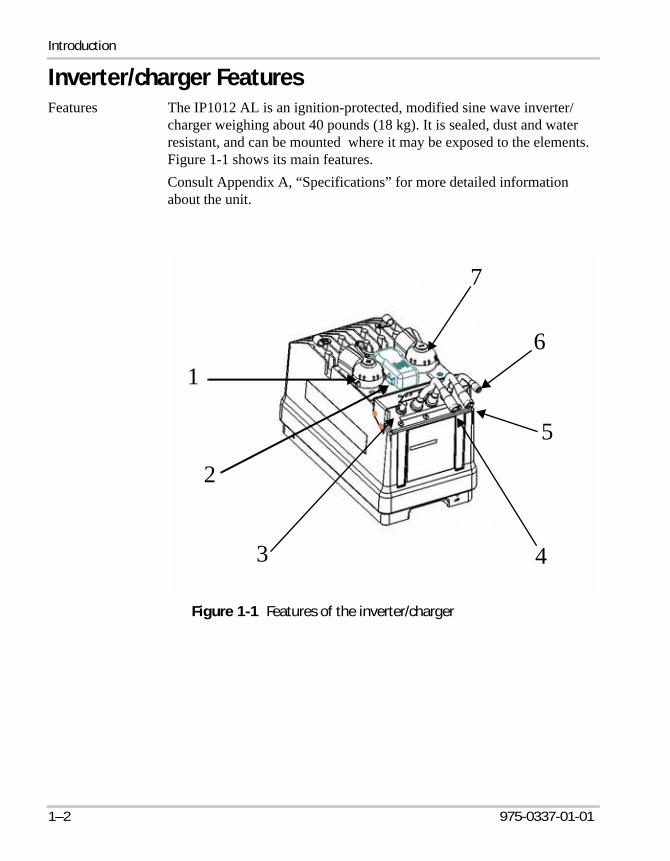
Inverter/charger FeaturesFeatures The IP1012 AL is an ignition-protected, modified sine wave inverter/
charger weighing about 40 pounds (18 kg). It is sealed, dust and water resistant, and can be mounted where it may be exposed to the elements. Figure 1-1 shows its main features.Consult Appendix A, “Specifications” for more detailed information about the unit.
Figure 1-1 Features of the inverter/charger
7
16
4
5
2
3
IP1012_AL.book Page 2 Tuesday, May 1, 2007 12:18 PM
Operating Features
975-0337-01-01 1–3
Location Ignition protection for safe operation in applications that require ignition protected equipment such as gasoline engine rooms or in a battery box.Ingress protected (IP66) for wet applications where the inverter will be cleaned with low pressure jets of water.
Operating FeaturesInverter/charger The inverter/charger functions as an inverter or as a charger depending
upon the operational conditions. When the unit is inverting, it is said to be in invert mode and is referred to as an inverter. When the unit is charging, it is in charge mode and is referred to as a charger.The unit can only operate in charge mode when external AC power referred to as “shorepower” is connected.
Inverter features
The IP1012 AL offers the following inverter features:• Ability to run many of the same appliances that you use at home
You can operate TVs, VCRs, satellite receivers, computers, hair dryers, and small power tools for example. You can also run multiple loads up to 1000 watts in total.
• Surge capabilityThe IP1012 AL will manage loads up to 3000 watts for short periods of time as long as the peak current is less than 36 amps.
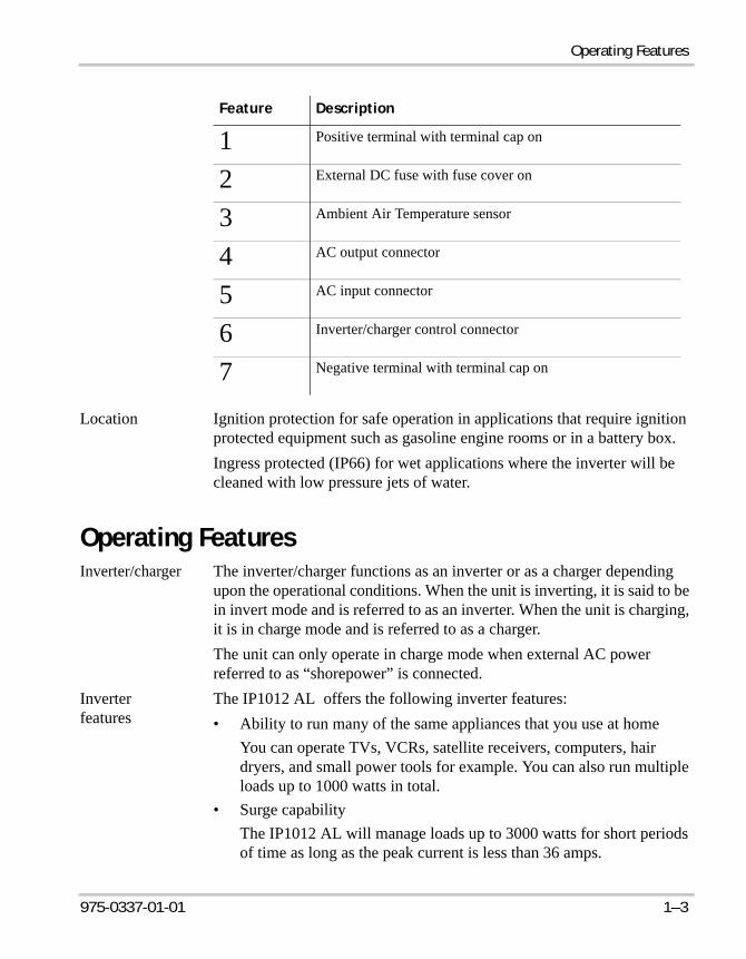
Feature Description
1 Positive terminal with terminal cap on
2 External DC fuse with fuse cover on
3 Ambient Air Temperature sensor
4 AC output connector
5 AC input connector
6 Inverter/charger control connector
7 Negative terminal with terminal cap on
IP1012_AL.book Page 3 Tuesday, May 1, 2007 12:18 PM

Introduction
1–4 975-0337-01-01
• Low voltage shutdownThe inverter shuts off when your batteries reach a predetermined voltage set in the microprocessor to protect batteries from permanent damage. Low voltage shutdown also monitors frequency and voltage, and protects against overload, short circuits and over-temperature.
• Automatic shutdown after 8 hours for loads less than 15 ±5 watts This feature prevents the inverter from draining the batteries if it is left on without a load.
Charger features
The IP1012 AL offers the following charger features:• 3-stage charging with 50 amps maximum charging current for 12V
battery type when shorepower is connected, to ensure your batteries are always charged
• Automatic transfer to invert modeWhen the AC shorepower cord is disconnected, the unit automatically switches to invert mode. When AC shorepower is available again, the inverter automatically switches to charging/pass-through mode.
• Load management capability which temporarily reduces charging current to the batteries when a large AC load is applied to the inverter output. This capability helps reduce the chance of tripping the shorepower breaker.
IP1012_AL.book Page 4 Tuesday, May 1, 2007 12:18 PM

2 Operation
Chapter 2, “Operation” explains how to calculate the size of the loads you can run from the IP1012 AL. It also provides guidelines to help you run loads safely and efficiently.
IP1012_AL.book Page 1 Tuesday, May 1, 2007 12:18 PM

Operation
2–2 975-0337-01-01
Planning for AC LoadsAC load AC load refers to an AC appliance you want to operate from the inverter/
charger. Loads include most appliances that you can plug into a standard 120 volt household electrical outlet.
Variables affecting AC loads
The IP1012 AL inverter/charger can power a wide range of loads. The size of the load and the length of time you can operate it depends on variables such as: • type of load,• ambient temperature, • size, state of charge, temperature, and condition of batteries.
The larger your battery capacity and the higher the state of charge, the longer the inverter/charger can run your AC loads. Battery capacity is reduced as battery temperature lowers.
Type of Loads
AC loads
The way in which an AC load draws power may determine how effectively it can be powered from the inverter/charger.
Resistive loads Toasters, coffee pots, and incandescent lights are examples of resistive loads which do not need a high start-up current to start running. They use a resistive heater element to generate heat or light. They are the simplest and easiest loads for an inverter/charger to run. Large resistive loads, such as electric stoves and water heaters, are impractical since their high power requirements quickly drain the batteries.
Inductive loads TVs, VCRs, stereos, computers, and electric motors (power tools, vacuum cleaners, for example) are examples of inductive loads which surge on start up. They require a high startup current compared to a resistive load such as a toaster or coffee pot. Depending upon its size, the motor can take as much as six times of its operating current to start than it does to keep it running once it has started. This surge can sometimes exceed the inverter/charger’s maximum output rating and the inverter will shut down.
IP1012_AL.book Page 2 Tuesday, May 1, 2007 12:18 PM

Planning for AC Loads
975-0337-01-01 2–3
DC loads
DC loads are those that run off a 12 volt electrical system. A few examples of DC loads are:• marker lights, headlights, vehicle lighting, other lights using DC
power• DC refrigerators• VHF radios• factory-installed radios or sound systems• pumps, lights, fans, power vents, LPG leak detector, toilet, and some
water heaters.DC loads and the inverter/charger both rely on the batteries for power. Many DC loads running at one time will shorten the operating times of AC loads.
Problem loads
Problem loads are loads you should not operate from the inverter/charger because they may be damaged or may not operate properly:• dimmer switches• some small rechargeable hand-power tools• small battery-operated appliances such as flashlights, razors, night
lights• variable speed motors
Ambient Temperature
Ambient temperature
The ambient temperature, that is, the air temperature around the inverter/charger, will affect its output power. Ambient temperature can rise when the vehicle is exposed to hot weather conditions or cabin heat from heaters.
Temperature and power
Generally, the output power decreases as the temperature increases. For example, at 77 °F (25 °C) the unit delivers 1000 watts for as long as you have sufficient battery power. At 104 °F (40 °C) it delivers 1000 watts for up to 30 minutes before shutting down, 2000 watts for 2 minutes, or 750 watts continuous.
IP1012_AL.book Page 3 Tuesday, May 1, 2007 12:18 PM

Operation
2–4 975-0337-01-01
Figure 2-1 shows the relationship between ambient temperatures and the length of time the unit will supply an output power level. Choose the curve with the temperature range most closely approximating that of the inverter/charger location, then look for the time in minutes. The intersection of the time and temperature will indicate approximately the output power of the unit. For example, between – 40 °F and 77 °F (-40 °C to 25 °C), you will get 3000 watts for approximately one minute or 2500 watts for 3 minutes. Times shown in this graph may vary with the actual operating conditions.
Calculating Size of an AC Load
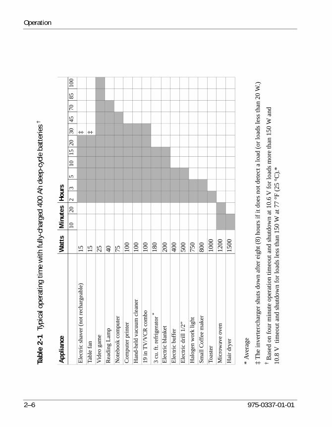
Operating time To determine how long you can run your loads:1. List all the AC loads you think you will use and determine their
power requirement. You can usually find this information on a label near the power cord on the appliance.
2. Look in Table 2-1 on page 2–6 to find the load’s operating time or the operating time of a similarly sized appliance. The operating times shown in the table indicate approximately how long a load will run before the inverter/charger shuts down to prevent battery damage.
Figure 2-1 Output power versus time and temperature
0
500
1000
1500
2000
2500
3000
1 10 100Time (minutes)
Out
put P
ower
(VA
)
-40 to 25C 40C 55C 70C 85C
– 40 to 77 F 104 F 131 F 158 F 185 F
IP1012_AL.book Page 4 Tuesday, May 1, 2007 12:18 PM

Planning for AC Loads
975-0337-01-01 2–5
3. To find the running time for several loads running simultaneously, add their total wattage and look for an appliance with similar power requirement in Table 2-1.
Battery condition
The information in Table 2-1 assumes:• there is a properly maintained 12 volt 400 amp-hour battery bank, for
example, 4 Group 31 (100Ah) deep-cycle truck batteries or 2 Group 4D batteries
• the batteries have not been damaged by deep discharge and are relatively new
Factors affecting load
Consider these factors when you are calculating loads:• Loads that exceed 1000 watts may be run for a short time (about one
minute).• Loads which run continuously such as a reading light, TV or
computer should not exceed more than 1000 watts in total.• Poor battery condition, low battery capacity, low battery temperature,
and high ambient temperature will shorten the operating times listed in the table.
• The presence of DC loads will reduce the operating times of the AC loads.
IP1012_AL.book Page 5 Tuesday, May 1, 2007 12:18 PM
Operation
2–6 975-0337-01-01
* Av
erag
e
‡ Th
e in
verte
r /cha
rger
shut
s dow
n af
ter e
ight
(8) h
ours
if it
doe
s not
det
ect a
load
(or l
oads
less
than
20
W.)
† Bas
ed o
n fo
ur m
inut
e op
erat
ion
timeo
ut a
nd sh
utdo
wn
at 1
0.6
V fo
r loa
ds m
ore
than
150
W a
nd
10.8
V t
imeo
ut a
nd sh
utdo
wn
for l
oads
less
than
150
W a
t 77
°F (2
5 °C
).*
Tabl
e 2-
1Ty
pica
l ope
ratin
g tim
e w
ith fu
lly-c
harg
ed 4
00 A
h de
ep-c
ycle
bat
terie
s †
App
lianc
eW
atts
Min
utes
Hou
rs10
202
35
10
15 2
0 30
4570
8510
0El
ectri
c sh
aver
(not
rech
arge
able
)15
‡Ta
ble
fan
15‡
Vid
eo g
ame
25R
eadi
ng L
amp
40N
oteb
ook
com
pute
r75
Com
pute
r prin
ter
100
Han
d-he
ld v
acuu
m c
lean
er10
019
in T
V/V
CR
com
bo10
03
cu. f
t. re
frig
erat
or *
180
Elec
tric
blan
ket
200
Elec
tric
buffe
r40
0El
ectri
c dr
ill 1
/2”
500
Hal
ogen
wor
k lig
ht75
0Sm
all C
offe
e m
aker
800
Toas
ter
1000
Mic
row
ave
oven
1200
Hai
r dry
er15
00
IP1012_AL.book Page 6 Tuesday, May 1, 2007 12:18 PM
Planning for AC Loads
975-0337-01-01 2–7
Running the Alternator While Operating AC and DC Loads
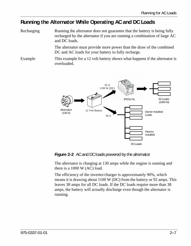
Recharging Running the alternator does not guarantee that the battery is being fully recharged by the alternator if you are running a combination of large AC and DC loads. The alternator must provide more power than the draw of the combined DC and AC loads for your battery to fully recharge.
Example This example for a 12 volt battery shows what happens if the alternator is overloaded.
The alternator is charging at 130 amps while the engine is running and there is a 1000 W (AC) load.The efficiency of the inverter/charger is approximately 90%, which means it is drawing about 1100 W (DC) from the battery or 92 amps. This leaves 38 amps for all DC loads. If the DC loads require more than 38 amps, the battery will actually discharge even though the alternator is running.
Figure 2-2 AC and DC loads powered by the alternator
12 Volt BatteryAlternator(130 A)
IP1012 AL
DC Loads
AC Loads(1000 W)
Owner InstalledLoads
FactoryInstalled
92 A1100 W (DC)
38 A
IP1012_AL.book Page 7 Tuesday, May 1, 2007 12:18 PM
Operation
2–8 975-0337-01-01
Indication If the alternator is overloaded the:• battery voltage gauge on the instrument panel begins dropping from
approximately 14 volts towards 12 volts,• battery power on the remote switch indicator signals a low battery
with a slow blink,• inverter shuts down at 10.4 volts and AC loads will stop operating.
The battery voltage gauge will climb again as the alternator now has enough power to charge the battery
Solutions You can reduce the AC or DC load on the battery or, for continuous operation of large AC and DC loads you can consider installing a larger alternator.
Comment Small alternator overloads may not be immediately noticeable and can take several hours to discharge the batteries. Large overloads will discharge the battery in a shorter time.At low engine RPMs the alternator current will drop significantly causing alternator overload to occur even with reduced AC and DC loads.
IP1012_AL.book Page 8 Tuesday, May 1, 2007 12:18 PM
Using the Remote Switch
975-0337-01-01 2–9
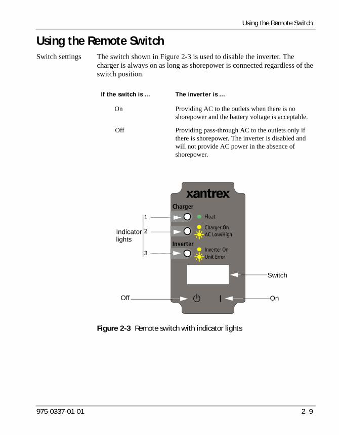
Using the Remote SwitchSwitch settings The switch shown in Figure 2-3 is used to disable the inverter. The
charger is always on as long as shorepower is connected regardless of the switch position.
If the switch is … The inverter is …
On Providing AC to the outlets when there is no shorepower and the battery voltage is acceptable.
Off Providing pass-through AC to the outlets only if there is shorepower. The inverter is disabled and will not provide AC power in the absence of shorepower.
Figure 2-3 Remote switch with indicator lights
OnOff
Switch
Indicatorlights
1
2
3
IP1012_AL.book Page 9 Tuesday, May 1, 2007 12:18 PM

Operation
2–10 975-0337-01-01
Switch indicators lights
The switch indicator lights (i.e., LED) provide information about the operating state of the inverter/charger. Under normal operating conditions the lights will behave like this:
1
Float When green LED is solid ON, the charge cycle is completed. It also means that the Charger On yellow LED turns off.
2
Charger On When yellow LED is solid ON, it indicates that:AC shore power is within operating voltage range,relay is connected from shore power to AC output, and the charger is actively charging.
AC Low/High When yellow LED is flashing, it indicates that although AC shore power is present, that it may or may not be within the operating voltage range. Refer to Table 4-2, “Charger indicator blink patterns” on page 4–4 for more information.
3
Inverter On When yellow LED is solid ON, it indicates the unit is currently inverting. Therefore, the AC output is active.
Unit Error When yellow LED is flashing, it indicates that a faulty condition has occurred. Refer to Table 4-3, “Inverter indicator blink patterns” on page 4–4 for more information.
Charger indicator lights
Inverter indicator light
IP1012_AL.book Page 10 Tuesday, May 1, 2007 12:18 PM

Operating the Inverter/Charger
975-0337-01-01 2–11
Operating the Inverter/ChargerThis section provides guidelines for operating the IP1012 AL.
Turning the Inverter On and Running Loads
To run loads:1. Turn the remote switch on by pressing to the right.2. Check that the Inverter indicator is illuminated and Charge indicator
is off if you are not connected to shorepower.3. Connect appliances one at a time to the inverter/charger. Don’t
connect too many high-surge appliances at once. Some appliances may halt or dim momentarily while another is starting up.
Running in Extremes Of Hot or Cold Temperatures
Hot In extremely hot conditions, the inverter may shut down sooner than it would in normal or cold temperatures. When the ambient temperature is high, reduce the number of loads.
Cold In extreme cold temperatures, your batteries may have less stored energy. At 0 °F (– 18 °C) your battery has only half the standby power than it has at 77 °F (25 °C).
Restarting After a Shutdown
If the loads stop operating suddenly, it usually means that the battery voltage is too low or you have drawn too much power for too long. Try restarting the inverter by turning the switch off, then on again. If you are running several loads, try disconnecting one or two of them before restarting. If the load doesn’t start right away, let the inverter rest a few minutes, then try again. The sudden stoppage means your batteries should be recharged as soon as possible. If the inverter still refuses to power your loads, start the vehicle to charge the batteries.
Note: Turning the switch off, then on again to restart after a shutdown should only be considered a temporary measure. The batteries likely need to be recharged.
IP1012_AL.book Page 11 Tuesday, May 1, 2007 12:18 PM

Operation
2–12 975-0337-01-01
Battery Charging
Connection cord
When you are connected to shorepower, the Charge indicator is illuminated and the unit is both passing power through to the appliances and charging the batteries. To avoid low voltage problems, make sure your connection cord to shorepower is not too long or too light to support the loads you are running. A 12 gauge or larger extension cord is recommended.
AC voltage If the Charge indicator flashes slowly (about twice per second), this means the AC voltage is out of range and your batteries are not charging.
Using Shorepower
If you are running too many loads you may either trip the AC system breaker if one is installed, or the shorepower breaker. Reduce the load and reset the affected breaker. The charger will automatically reduce battery charging if other AC loads are connected. This feature helps to prevent nuisance tripping of the shorepower breaker.
Miscellaneous Hints
Automatic shutdown
The inverter automatically turns off if it has not detected any AC loads for 8 hours when AC load is less than 15W or the loads are so small the inverter cannot detect them, such as an alarm clock or a small television (less than 15W).
Output power The total output of the inverter/charger is 1000 watts..
Connect delay to AC power
If you are connected to shorepower, the Charge indicator should be on and the Inverter indicator off. The Charge indicator may blink slowly when you first apply shorepower because of a connect delay (about 30 seconds), but then will illuminate steadily.
Load failure If any loads fail to operate, or the inverter shuts down, refer to Chapter 4, “Troubleshooting” for suggestions.
Note: The IP1012 AL does not provide any warning before it shuts down. If you need to operate a critical AC load, be sure there are no heavy loads connected and that the batteries have been recently charged.
IP1012_AL.book Page 12 Tuesday, May 1, 2007 12:18 PM

3 Maintenance
Chapter 3, “Maintenance” provides procedures for • checking the terminal connections on the inverter/
charger• disconnecting the IP1012 AL from the batteries• changing the overcurrent protection fuse• removing or connecting the AC input and output
cables.
IP1012_AL.book Page 1 Tuesday, May 1, 2007 12:18 PM

Maintenance
3–2 975-0337-01-01
Maintaining the Inverter/chargerBefore doing any maintenance on the IP1012 AL, review all safety instructions in “Important Safety Information” on page v.
Checking TerminalsTo check that the battery cables are firmly connected, you will need to remove the terminal caps.To remove the terminal cap:1. Using a flathead screwdriver as shown in Figure 3-1, place the blade
in the lip of the cap and push it gently against the cap until it lifts off.2. To replace the cap, place it over the terminal and push down until it
snaps into place.
WARNINGThe metal base of the IP1012 AL may be hot when operating in high ambient temperatures. Do not touch the metal enclosure until the unit has cooled down.
Figure 3-1 Removing the terminal cap
1
2
3
IP1012_AL.book Page 2 Tuesday, May 1, 2007 12:18 PM
Disconnecting and Connecting the Batteries
975-0337-01-01 3–3
Disconnecting and Connecting the Batteries
Disconnecting
To disconnect from the battery: 1. Disconnect the shorepower cable and turn the inverter/charger off
from the remote switch.
2. Remove the inverter/charger cables from the battery by first disconnecting the negative cable at the inverter/charger. Then disconnect the positive and negative cables at the battery.
3. If you are replacing batteries, make sure they are flooded lead-acid or AGM batteries and that they are all the same capacity and age as the others in the bank.
4. Disconnect the ground wire if the unit must be removed from its mounting bracket.
Connecting
To connect to the batteries:1. Ensure shorepower is disconnected and the inverter/charger is off.2. Connect the ground wire if it was previously removed.
WARNING: Explosion or FireMake sure the battery compartment is well ventilated. Flammable fumes are often present when working with batteries.
Note: If you have a DC Disconnect installed, you should open it before proceeding to the next step.
CAUTION: Reverse PolarityDo not connect cables in reverse polarity. If you do, the fuse will blow and the unit could be damaged.
WARNING: Explosion or FireDo not proceed to the next step if flammable fumes are present. Explosion or fire may result. Thoroughly ventilate the battery compartment before making this connection.
IP1012_AL.book Page 3 Tuesday, May 1, 2007 12:18 PM

Maintenance
3–4 975-0337-01-01
3. To reconnect the cables:a) Connect one end of the positive battery cable to the IP1012 AL.b) Connect one end of the negative battery cable to the IP1012 AL.
c) Connect the other end of the positive battery cable to the positive terminal of the battery.
d) Connect the other end of the negative battery cable to the nega-tive terminal of the battery.
4. Tighten to a torque of 12 to 15 ft-lbs (+/-10%).
5. Check that the inverter is operating by enabling it from the remote switch as explained in “Using the Remote Switch” on page 2–9.
Replacing the Fuse
The inverter/charger external DC fuse, shown in Figure 1-1, protects the unit from causing wiring and battery damage due to over-current and from reverse polarity when connecting the unit to the battery. If the fuse blows for any reason, replace it with only the fuse types listed below.• Littelfuse Mega® Fast Blow, 250 A, 32 V; part number 298250• Bussmann® 250 A 48 V; part number AMG-250
WARNING: Possible popping sound and sparksFollow steps c) and d) in sequence. If you switch the steps, you may hear a “popping” sound and see sparks when you make that connection to the negative terminal. If flammable fumes are present, explosion or fire may result.
Note: If you have a DC Disconnect installed, you should close it before proceeding to the next step.
WARNING: Correct Fuse TypeTo reduce the risk of fire and electrical hazards, replace the fuse only with a fuse of the same type and rating.Using the wrong fuse type can damage the unit and void your warranty.
Note: Additional fusing may be required seven (7) inches from the battery post, if the inverter is located away from the batteries with long cable runs.
IP1012_AL.book Page 4 Tuesday, May 1, 2007 12:18 PM
Replacing the Fuse
975-0337-01-01 3–5
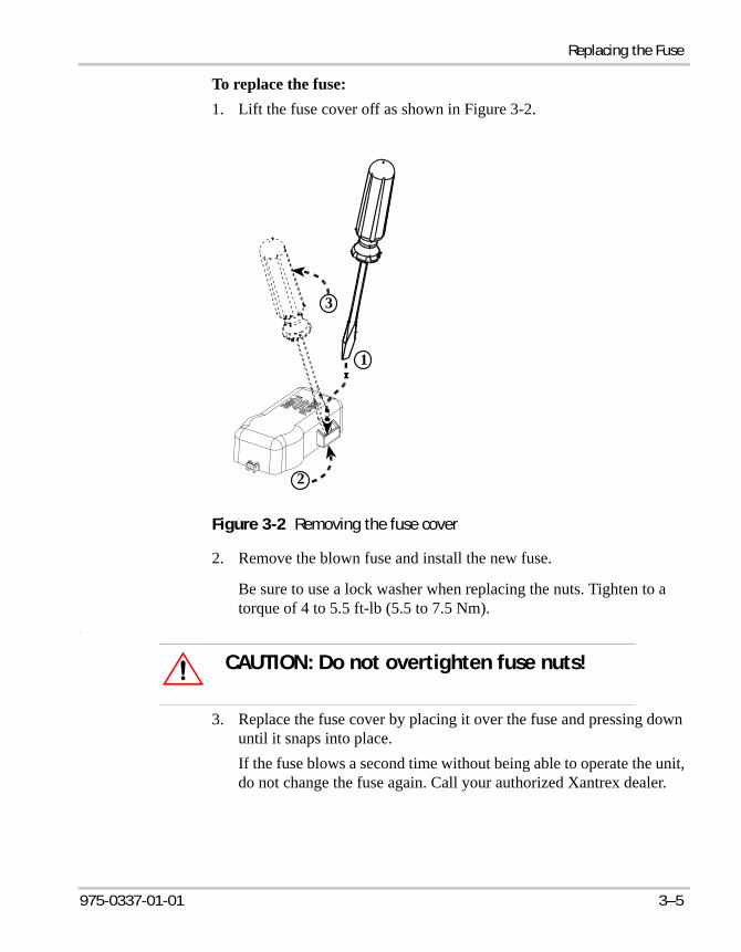
To replace the fuse:1. Lift the fuse cover off as shown in Figure 3-2.
2. Remove the blown fuse and install the new fuse.
Be sure to use a lock washer when replacing the nuts. Tighten to a torque of 4 to 5.5 ft-lb (5.5 to 7.5 Nm).
.
3. Replace the fuse cover by placing it over the fuse and pressing down until it snaps into place.If the fuse blows a second time without being able to operate the unit, do not change the fuse again. Call your authorized Xantrex dealer.
Figure 3-2 Removing the fuse cover
1
2
3
CAUTION: Do not overtighten fuse nuts!
IP1012_AL.book Page 5 Tuesday, May 1, 2007 12:18 PM

Maintenance
3–6 975-0337-01-01
Removing and Reconnecting AC CablesTo remove the AC cables:➣ Grasp the knurled surface of the connector housing as shown in
Figure 3-3 and turn counter clockwise approximately one-half turn. Gently pull the cable out by grasping the connector.
To reconnect:1. Align the key of the connector with the slot on the terminal of the
IP1012 AL.2. Insert the connector firmly. Turn the connector housing clockwise 1/2
turn until you feel resistance, then another 1/8 turn until it locks into place.
Figure 3-3 AC input and output cables
AC output connector AC input connector
Inverter/chargercontrol cable
IP1012_AL.book Page 6 Tuesday, May 1, 2007 12:18 PM

4 Troubleshooting
Chapter 4, “Troubleshooting” provides information to help you identify common problems which may occur. Read this chapter before calling your authorized Xantrex dealer. If you cannot solve the problem, record the details as suggested on “Information About Your System” on page WA–4, then call your dealer.
IP1012_AL.book Page 1 Tuesday, May 1, 2007 12:18 PM

Troubleshooting
4–2 975-0337-01-01
Troubleshooting
Common Problems
The unit shuts down during operation for four main reasons:• low battery—when the battery reaches approximately 10.6 Vdc for
more than four minutes with loads greater than 150 watts , or 10.8 Vdc for loads less than 150 watts. Low battery shutdown also occurs when battery voltage reaches 10.4 Vdc for three seconds.
• high battery—when the battery voltage exceeds 16 Vdc • overload—when the AC load connected to the inverter exceeds the
rated load• over temperature—when the internal temperature thresholds are
reachedTable 4-1 lists problems you may encounter and offers suggestions to fix them.
Table 4-1 Troubleshooting reference
Symptom Possible Problem Remedy
Loads will not start when there is no shorepower.
Inverter is not turned on.
Batteries are at low voltage.
Inverter is too hot
Turn the inverter on.
Recharge the batteries by running the engine or connecting to shorepower.
Wait until the inverter has cooled down.
Loads stop running almost as soon as they start.
Load is too heavy.
Batteries are at low voltage level.
Bad battery cable or corroded battery terminals.
Batteries are in poor condition.
Reduce the load.
Recharge the batteries by running the engine or connecting to shorepower.
Check the cable and connectors.
Test and replace, if necessary
IP1012_AL.book Page 2 Tuesday, May 1, 2007 12:18 PM

Troubleshooting
975-0337-01-01 4–3
Blinking Lights on the Remote Switch
You may encounter different sequences of blinking lights when the inverter is enabled (i.e., switch is on) or the unit is charging. Light sequences are described as follows:
Loads stop operating without warning after they have been running. Shorepower is not connected.
Too many appliances have reduced the battery voltage to shutdown level.
Ambient temperature is too high.
Reduce the number of loads. Allow the inverter to cool and restart. Recharge the batteries.
Disconnect appliances and let the unit cool down.
The inverter will not work even after toggling the switch, charging the batteries, and letting the unit cool down.
Remote switch may be disconnected at the unit
Fuse on the unit (shown in Figure 1-1) may have blown
Check that the remote switch is firmly connected.
Replace the fuse or return the unit to an authorized Xantrex dealer.
AC voltage at receptacles reads low.
Wrong type of voltmeter being used.
Use a true RMS meter
In inverter mode, times to shutdown are getting shorter for the same kind of AC load
Bad battery cable or corroded battery terminals.Batteries too old or damaged.
Check the cables and connectors
Replace the batteries.
Table 4-1 Troubleshooting reference (Continued)
Symptom Possible Problem Remedy
Blink Level 1 Fast blink Light is on for 1/4 second and off for 1/4 second
Blink Level 2 Slow blink Light is on for 1/2 second and off for 1/2 second
Blink Level 3 Very slow blink Light is on for one second and off for one second
IP1012_AL.book Page 3 Tuesday, May 1, 2007 12:18 PM
Troubleshooting
4–4 975-0337-01-01
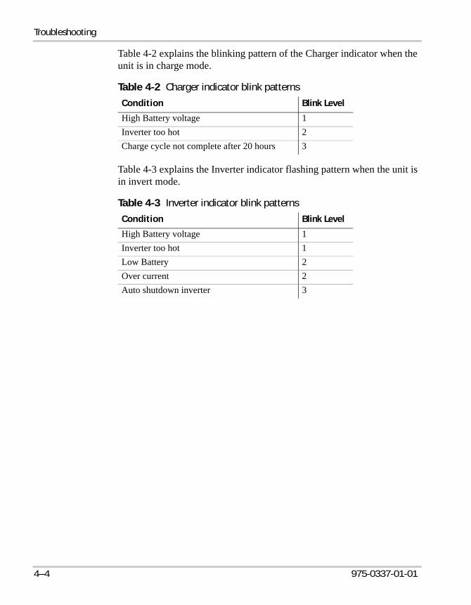
Table 4-2 explains the blinking pattern of the Charger indicator when the unit is in charge mode.
Table 4-3 explains the Inverter indicator flashing pattern when the unit is in invert mode.
Table 4-2 Charger indicator blink patterns
Condition Blink Level
High Battery voltage 1Inverter too hot 2Charge cycle not complete after 20 hours 3
Table 4-3 Inverter indicator blink patterns
Condition Blink Level
High Battery voltage 1Inverter too hot 1Low Battery 2Over current 2Auto shutdown inverter 3
IP1012_AL.book Page 4 Tuesday, May 1, 2007 12:18 PM

A Specifications
Appendix A contains the inverter, charger, and transfer specifications for the IP1012 AL. The specifications show rating curves for output surge, current versus temperature, and pass-through current. Appendix A also illustrates the three-stage charging profile used by the unit.All specifications are subject to change without notice.
IP1012_AL.book Page 1 Tuesday, May 1, 2007 12:18 PM
Specifications
A–2 975-0337-01-01
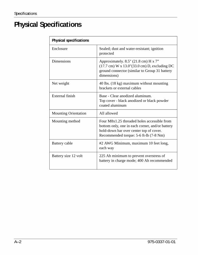
Physical Specifications
Physical specifications
Enclosure Sealed; dust and water-resistant; ignition protected
Dimensions Approximately. 8.5" (21.8 cm) H x 7” (17.7 cm) W x 13.0"(33.0 cm) D, excluding DC ground connector (similar to Group 31 battery dimensions)
Net weight 40 lbs. (18 kg) maximum without mounting brackets or external cables
External finish Base - Clear anodized aluminum. Top cover - black anodized or black powder coated aluminum
Mounting Orientation All allowed
Mounting method Four M8x1.25 threaded holes accessible from bottom only, one in each corner, and/or battery hold-down bar over center top of cover. Recommended torque: 5-6 ft-lb (7-8 Nm)
Battery cable #2 AWG Minimum, maximum 10 feet long, each way
Battery size 12 volt 225 Ah minimum to prevent overstress of battery in charge mode; 400 Ah recommended
IP1012_AL.book Page 2 Tuesday, May 1, 2007 12:18 PM

Inverter Specifications
975-0337-01-01 A–3
Inverter SpecificationsAll inverter specifications are at nominal conditions; 1000 W resistive load, 12 Vdc inverting on the IP1012 AL, 120 Vac, unless otherwise specified.
Inverter specifications
Output wave form Modified sine wave
Output power continuous 1000 Vac continuous
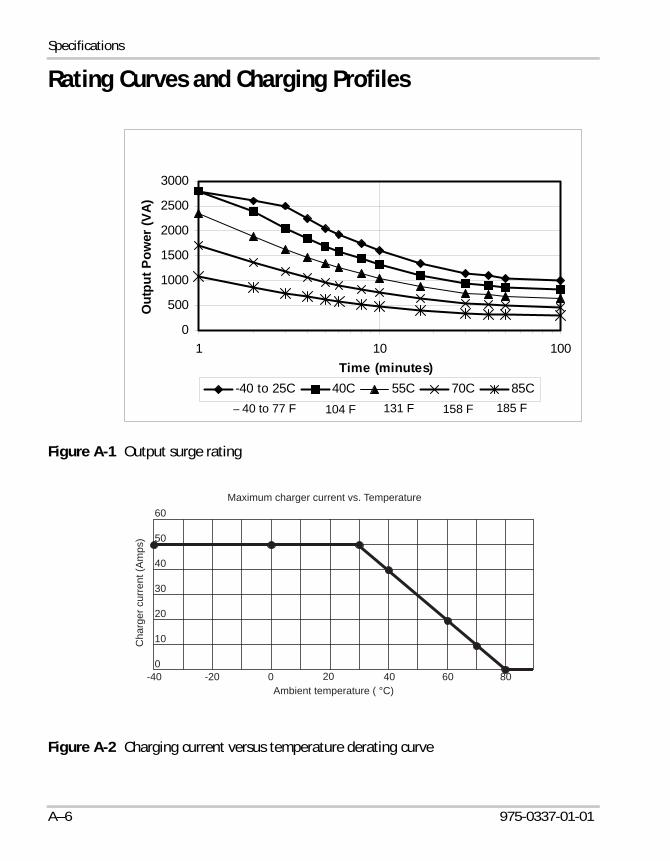
Surge rating 3000 VA for 30 seconds at –40 °F to 77 °F (–40 °C to 25 °C)See Figure A-1 for output at different temperatures.
Operating voltage range 10.4 Vdc to 16.0 Vdc
Input DC voltage rating 12 Vdc
Output voltage 120 Vac RMS
Output voltage regulation 108 to 125 Vac under steady state 0 to 1000 W load with 10.6 to 14.5 Vdc input at 25 °C (77 °F)
108 to 132 Vac up to 1000 W, 10.6 to 16 Vdc input at – 40 °F to 185 °F (–40 °C to 85 °C)
Output frequency 60.0 ± 0.1 Hz from – 40 °F to 185 °F (– 40 °C to 85 °C) ambient temperature
Power factor allowed All (0 to 1, leading or lagging)
Peak efficiency Greater than 93% at 12.6 Vdc input at 77 °F (25 °C)
Idle power consumption Less than 15 W (inverting with 120 Vac output and no load)
Auto-shutdown mode Inverter output is less than 15 ±5 W and battery is less than 13 Vdc for 8 hours
Off mode power consumption
Less than 120 mW when inverter switch is off or in auto off mode
IP1012_AL.book Page 3 Tuesday, May 1, 2007 12:18 PM
Specifications
A–4 975-0337-01-01
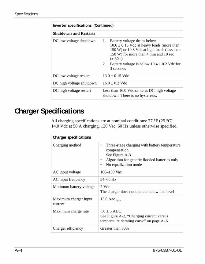
Charger SpecificationsAll charging specifications are at nominal conditions: 77 °F (25 °C), 14.0 Vdc at 50 A charging, 120 Vac, 60 Hz unless otherwise specified.
Shutdowns and Restarts
DC low voltage shutdown 1. Battery voltage drops below 10.6 ± 0.15 Vdc at heavy loads (more than 150 W) or 10.8 Vdc at light loads (less than 150 W) for more than 4 min and 10 sec (± 30 s)
2. Battery voltage is below 10.4 ± 0.2 Vdc for 3 seconds
DC low voltage restart 13.0 ± 0.15 Vdc
DC high voltage shutdown 16.0 ± 0.2 Vdc
DC high voltage restart Less than 16.0 Vdc same as DC high voltage shutdown. There is no hysteresis.
Inverter specifications (Continued)
Charger specifications
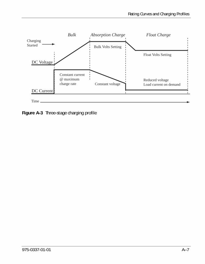
Charging method • Three-stage charging with battery temperature compensation.See Figure A-3.
• Algorithm for generic flooded batteries only• No equalization mode
AC input voltage 100–130 Vac
AC input frequency 54–66 Hz
Minimum battery voltage 7 Vdc The charger does not operate below this level
Maximum charger input current
13.0 Aac rms
Maximum charge rate 50 ± 5 ADC. See Figure A-2, “Charging current versus temperature derating curve” on page A–6
Charger efficiency Greater than 80%
IP1012_AL.book Page 4 Tuesday, May 1, 2007 12:18 PM

Transfer and General Specifications
975-0337-01-01 A–5
Transfer and General Specifications
Absorption charge voltage 14.3 ± 0.3 Vdc at 77 °F (25 °C)
Float charge voltage 13.3 ± 0.3 Vdc at 77 °F (25 °C)
Temperature compensation – 0.023 Vdcfrom -2 °C to 85 °C (28.4 °F to 185 °F).Below -2 °C, the charger voltage defaults to the – 2 °C voltage
Overvoltage shutdown Greater than or equal to 15.3 ± 0.3 Vdc
Transfer and general specifications
AC input/bypass current 15 AAC maximum continuous at 122 °F (50 °C)Derates to 5 AAC at 185 °F (85 °C)
Transfer speed 10–40 ms typical
AC low voltage transfer 90 ± 5 Vac
AC low voltage restart 95 ± 5 Vac, 30 second delay
AC high voltage transfer None
Standby/off consumption < 0.7 watts at 12.5 Vdc with charger and inverter both off
Operating temperature range – 40 °F to +185 °F (– 40 °C to +85 °C)
Storage temperature range – 40 °F to +185 °F (– 40 °C to +85 °C)
Altitude limit 15 000 feet (5000 metres)
AC neutral to ground bonding Invert mode: AC output neutral is connected to AC ground (chassis).Charge mode: AC output neutral is connected to AC input neutral.
AC input neutral is always isolated from AC ground.
Charger specifications (Continued)
IP1012_AL.book Page 5 Tuesday, May 1, 2007 12:18 PM
Specifications
A–6 975-0337-01-01
Rating Curves and Charging Profiles
Figure A-1 Output surge rating
Figure A-2 Charging current versus temperature derating curve
0
500
1000
1500
2000
2500
3000
1 10 100Time (minutes)
Out
put P
ower
(VA)
-40 to 25C 40C 55C 70C 85C104 F 131 F 158 F 185 F– 40 to 77 F
Maximum charger current vs. Temperature
Cha
rger
cur
rent
(Am
ps)
Ambient temperature ( °C)-40 -20 0 20 40 60 80
0
10
20
30
40
50
60
IP1012_AL.book Page 6 Tuesday, May 1, 2007 12:18 PM
Rating Curves and Charging Profiles
975-0337-01-01 A–7
Figure A-3 Three-stage charging profile
Bulk
DC Voltage
DC Current
ChargingStarted
Constant current@ maximumcharge rate Constant voltage
Reduced voltageLoad current on demand
Float Volts Setting
Bulk Volts Setting
Time
Absorption Charge Float Charge
IP1012_AL.book Page 7 Tuesday, May 1, 2007 12:18 PM

A–8
IP1012_AL.book Page 8 Tuesday, May 1, 2007 12:18 PM

975-0337-01-01 IX-1
AAC cables, removing or connecting 3–6AC load
calculating size 2–4definition 2–2factors affecting 2–2types of 2–2
AC power, connect delay 2–12alternator, effects of overloading 2–7ambient temperature
effect on operation 2–2, 2–11effect on output power 2–3
appliances see AC loadbattery-operated vi
auto shutdown feature 1–4automatic shutdown 2–12automatic transfer between AC and DC 1–4
Bbatteries
disconnecting from 3–3nickel-cadmium viprecautions for working with vi
battery charging 2–12battery condition, effect on AC loads 2–5battery operated appliances see problem loadsbattery packs vibreaker switch
resetting 2–12
Ccharger features 1–3charger specifications A–4charging batteries 2–12cold temperatures, running in 2–11connect delay to AC power 2–12connection cord, recommended size 2–12current vs temperature derating curve A–6
Customer Servicepreparing to call WA–4
DDC loads
effect on alternator 2–7effect on operating times of AC loads 2–3
derating curves, current vs temperature A–6dimmer switch see problem loadsdisconnecting from batteries 3–3
Eextension cord see connection cord
FFeatures of inverter•charger 1–2flashlights see problem loadsfuse, replacing 3–4
Hhigh battery shutdown 4–2hot temperatures, running in 2–11
Iindicator lights
blinking patterns 4–2inductive load see AC loadsInformation about Your System form WA–4inverter
purchase date WA–4serial number WA–4
inverter features 1–3inverter specifications A–3
Lload management capability 1–4
Index
IP1012_AL.book Page 1 Tuesday, May 1, 2007 12:18 PM

Index
IX–2 975-0337-01-01
loads, effect of large loads on alternator 2–7low battery shutdown 4–2low voltage shutdown 1–4
Mmaintenance
checking terminal connections 3–2replacing the fuse 3–4
Nnickel-cadmium batteries vi
Ooperating time of AC loads (table) 2–6output power of IP 1012 2–12over temperature shutdown 4–2overload shutdown 4–2
Pphysical specifications A–2problem loads 2–3problems causing shutdown 4–2proof of purchase WA–4purchase date WA–4
Rrating curves
output surge rating A–5razors see problem loadsrechargeable tools see problem loadsremote switch
blinking lights on the 4–3remote switch to disable inverter 2–9resistive load see AC load, type ofresistive loads, examples of 2–2restarting after shutdown 2–11
Ssafety information vsafety monitoring feature 1–4serial number WA–4
servicing, no user-serviceable parts vshorepower, definition 1–3shutdown
automatic 2–12restarting after 2–11
shutdown, reasons for 4–2size of AC load, calculating 2–4surge capability 1–3surge loads, examples of 2–2
Ttemperature see ambient temperaturetemperature and power, relationship of 2–4temperature and time derating curve (figure) 2–4terminals caps, removing 3–2three-stage charging profile A–6time, running time of AC loads 2–4transfer specifications A–5troubleshooting reference 4–2turning on unit with the remote switch 2–11
Uusing , guidelines for 2–11
Vvariable speed motor see problem loads
Wwarranty
out of warranty service WA–4terms and conditions WA–1
XXantrex
web site iv
IP1012_AL.book Page 2 Tuesday, May 1, 2007 12:18 PM

975-0337-01-01 WA–1
Warranty and Return Information
WarrantyWhat does this warranty cover? This Limited Warranty is provided by Xantrex Technology Inc. ("Xantrex") and covers defects in workmanship and materials in your IP1012 AL Inverter/Charger with Ignition Protection. This warranty period lasts for one (1) year from the date of purchase at the point of sale to you, the original end user customer. You will be required to demonstrate proof of purchase to make warranty claims.This Limited Warranty is transferable to subsequent owners but only for the unexpired portion of the Warranty Period. Subsequent owners also require original proof of purchase as described “What proof of purchase is required?”What will Xantrex do? Xantrex will, at its option, repair or replace the defective product free of charge, provided that you notify Xantrex of the product defect within the Warranty Period, and provided that Xantrex through inspection establishes the existence of such a defect and that it is covered by this Limited Warranty. Xantrex will, at its option, use new and/or reconditioned parts in performing warranty repair and building replacement products. Xantrex reserves the right to use parts or products of original or improved design in the repair or replacement. If Xantrex repairs or replaces a product, its warranty continues for the remaining portion of the original Warranty Period or 90 days from the date of the return shipment to the customer, whichever is greater. All replaced products and all parts removed from repaired products become the property of Xantrex.Xantrex covers both parts and labor necessary to repair the product, and return shipment to the customer via a Xantrex-selected non-expedited surface freight within the contiguous United States and Canada. Alaska and Hawaii are excluded. Contact Xantrex Customer Service for details on freight policy for return shipments outside of the contiguous United States and Canada.How do you get service? If your product requires troubleshooting or warranty service, contact your merchant. If you are unable to contact your merchant, or the merchant is unable to provide service, contact Xantrex directly at:
Direct returns may be performed according to the Xantrex Return Material Authorization Policy described in your product manual. For some products, Xantrex maintains a network of regional Authorized Service Centers. Call Xantrex or check our website to see if your product can be repaired at one of these facilities.
Telephone: 1 800 670 0707 (toll free North America)1 360 925 5097 (direct)
Fax: 1 800 994 7828 (toll free North America)1 360 925 5143 (direct)
Email: [email protected]
IP1012_AL.book Page 1 Tuesday, May 1, 2007 12:18 PM
Warranty and Return
WA–2 975-0337-01-01
What proof of purchase is required? In any warranty claim, dated proof of purchase must accompany the product and the product must not have been disassembled or modified without prior written authorization by Xantrex. Proof of purchase may be in any one of the following forms:• The dated purchase receipt from the original purchase of the product at point of sale to the end user,
or• The dated dealer invoice or purchase receipt showing original equipment manufacturer (OEM)
status, or• The dated invoice or purchase receipt showing the product exchanged under warrantyWhat does this warranty not cover? This Limited Warranty does not cover normal wear and tear of the product or costs related to the removal, installation, or troubleshooting of the customer's electrical systems. This warranty does not apply to and Xantrex will not be responsible for any defect in or damage to:a) the product if it has been misused, neglected, improperly installed, physically damaged or altered,
either internally or externally, or damaged from improper use or use in an unsuitable environment;b) the product if it has been subjected to fire, water, generalized corrosion, biological infestations, or
input voltage that creates operating conditions beyond the maximum or minimum limits listed in the Xantrex product specifications including high input voltage from generators and lightning strikes;
c) the product if repairs have been done to it other than by Xantrex or its authorized service centers (hereafter "ASCs");
d) the product if it is used as a component part of a product expressly warranted by another manufac-turer;
e) the product if its original identification (trade-mark, serial number) markings have been defaced, altered, or removed.
Disclaimer
ProductTHIS LIMITED WARRANTY IS THE SOLE AND EXCLUSIVE WARRANTY PROVIDED BY XANTREX IN CONNECTION WITH YOUR XANTREX PRODUCT AND IS, WHERE PERMITTED BY LAW, IN LIEU OF ALL OTHER WARRANTIES, CONDITIONS, GUARANTEES, REPRESENTATIONS, OBLIGATIONS AND LIABILITIES, EXPRESS OR IMPLIED, STATUTORY OR OTHERWISE IN CONNECTION WITH THE PRODUCT, HOWEVER ARISING (WHETHER BY CONTRACT, TORT, NEGLIGENCE, PRINCIPLES OF MANUFACTURER'S LIABILITY, OPERATION OF LAW, CONDUCT, STATEMENT OR OTHERWISE), INCLUDING WITHOUT RESTRICTION ANY IMPLIED WARRANTY OR CONDITION OF QUALITY, MERCHANTABILITY OR FITNESS FOR A PARTICULAR PURPOSE. ANY IMPLIED WARRANTY OF MERCHANTABILITY OR FITNESS FOR A PARTICULAR PURPOSE TO THE EXTENT REQUIRED UNDER APPLICABLE LAW TO APPLY TO THE PRODUCT SHALL BE LIMITED IN DURATION TO THE PERIOD STIPULATED UNDER THIS LIMITED WARRANTY.IN NO EVENT WILL XANTREX BE LIABLE FOR ANY SPECIAL, INDIRECT, INCIDENTAL OR CONSEQUENTIAL DAMAGES, LOSSES, COSTS OR EXPENSES HOWEVER ARISING WHETHER IN CONTRACT OR TORT INCLUDING WITHOUT RESTRICTION ANY ECONOMIC LOSSES OF ANY KIND, ANY LOSS OR DAMAGE TO PROPERTY, ANY PERSONAL INJURY, ANY DAMAGE OR INJURY ARISING FROM OR AS A RESULT OF MISUSE OR ABUSE, OR THE INCORRECT INSTALLATION, INTEGRATION OR OPERATION OF THE PRODUCT.
IP1012_AL.book Page 2 Tuesday, May 1, 2007 12:18 PM

Warranty and Return
975-0337-01-01 WA–3
ExclusionsIf this product is a consumer product, federal law does not allow an exclusion of implied warranties. To the extent you are entitled to implied warranties under federal law, to the extent permitted by applicable law they are limited to the duration of this Limited Warranty. Some states and provinces do not allow limitations or exclusions on implied warranties or on the duration of an implied warranty or on the limitation or exclusion of incidental or consequential damages, so the above limitation(s) or exclusion(s) may not apply to you. This Limited Warranty gives you specific legal rights. You may have other rights which may vary from state to state or province to province.
Return Material Authorization PolicyBefore returning a product directly to Xantrex you must obtain a Return Material Authorization (RMA) number and the correct factory "Ship To" address. Products must also be shipped prepaid. Product shipments will be refused and returned at your expense if they are unauthorized, returned without an RMA number clearly marked on the outside of the shipping box, if they are shipped collect, or if they are shipped to the wrong location.When you contact Xantrex to obtain service, please have your instruction manual ready for reference and be prepared to supply:• The serial number of your product• Information about the installation and use of the unit• Information about the failure and/or reason for the return• A copy of your dated proof of purchaseRecord these details in “Information About Your System” on page WA–4.
Return Procedure1. Package the unit safely, preferably using the original box and packing materials. Please ensure that
your product is shipped fully insured in the original packaging or equivalent. This warranty will not apply where the product is damaged due to improper packaging.
2. Include the following:• The RMA number supplied by Xantrex Technology Inc. clearly marked on the outside of the
box.• A return address where the unit can be shipped. Post office boxes are not acceptable.• A contact telephone number where you can be reached during work hours.• A brief description of the problem.
3. Ship the unit prepaid to the address provided by your Xantrex customer service representative.If you are returning a product from outside of the USA or Canada In addition to the above, you MUST include return freight funds and are fully responsible for all documents, duties, tariffs, and deposits. If you are returning a product to a Xantrex Authorized Service Center (ASC) A Xantrex return material authorization (RMA) number is not required. However, you must contact the ASC prior to returning the product or presenting the unit to verify any return procedures that may apply to that particular facility and that the ASC repairs this particular Xantrex product.
IP1012_AL.book Page 3 Tuesday, May 1, 2007 12:18 PM

Warranty and Return
WA–4 975-0337-01-01
Out of Warranty ServiceIf the warranty period for your IP1012 AL Inverter/Charger with Ignition Protection has expired, if the unit was damaged by misuse or incorrect installation, if other conditions of the warranty have not been met, or if no dated proof of purchase is available, your unit may be serviced or replaced for a flat fee.To return your IP1012 AL Inverter/Charger with Ignition Protection for out of warranty service, contact Xantrex Customer Service for a Return Material Authorization (RMA) number and follow the other steps outlined in “Return Procedure” on page WA–3. Payment options such as credit card or money order will be explained by the Customer Service Representative. In cases where the minimum flat fee does not apply, as with incomplete units or units with excessive damage, an additional fee will be charged. If applicable, you will be contacted by Customer Service once your unit has been received.
Information About Your SystemAs soon as you open your IP1012 AL Inverter/Charger with Ignition Protection package, record the following information and be sure to keep your proof of purchase.
If you need to contact Customer Service, please record the following details before calling. This information will help our representatives give you better service.
Serial Number ___________________________ Product Number 805-1011
Purchased From ___________________________ Purchase Date ________________
❐ Type of installation (e.g. RV, truck) ______________________________
❐ Length of time inverter has been installed ______________________________
❐ Battery/battery bank size ______________________________
❐ Battery type (e.g. flooded, sealed gel cell, AGM) ______________________________
❐ DC wiring size and length ______________________________
❐ Alarm sounding? ______________________________
❐ Description of indicators on front panel ______________________________
❐ Appliances operating when problem occurred ______________________________
❐ Description of problem ______________________________
________________________________________________________________________________
IP1012_AL.book Page 4 Tuesday, May 1, 2007 12:18 PM

IP1012_AL.book Page 5 Tuesday, May 1, 2007 12:18 PM

Xantrex Technology Inc.
1 800 670 0707 Tel toll free NA1 360 925 5097 Tel direct1 800 994 7828 Fax toll free NA1 360 925 5143 Fax [email protected]
975-0337-01-01 Printed in China
IP1012_AL.book Page 6 Tuesday, May 1, 2007 12:18 PM