owner‘s manual€¦ · “caution“ are of particularly high importance. the instructions...
TRANSCRIPT

OWNER‘S MANUAL
2019
-06-
THE
BR
UC
E-EN

1 Frame 10 Pedal
2 Saddle 11 Handlebar with grips and brake lever
3 Seat post 12 Suspension fork
4 Saddle clamp 13 Tyre
5 Brake caliper 14 Rim
6 Disc rotor 15 Hub
7 Adjustable dropout 16 Spoke
8 Chain
9 Crankset with chainring and bottom bracket
1
2
34
5
6
7
8
9 10
12
11
13
14
15
16

EN
3
1. General information ................................................................................................................ 5
1.1 Explanation of symbols used ......................................................................................................5
1.2 Target group .....................................................................................................................................5
1.3 Owner’s manuals supplied by component manufacturers ...............................................5
1.4 Tools ....................................................................................................................................................5
1.5 Installation of components and accessories ..........................................................................5
1.6 Warranty and guarantee ...............................................................................................................6
1.7 Wearing parts ...................................................................................................................................6
1.8 Weight limit .......................................................................................................................................6
1.9 Exclusion of liability .......................................................................................................................6
2. Safety ........................................................................................................................................ 7
2.1 General safety ..................................................................................................................................7
2.2 The rider’s duty of care .................................................................................................................7
2.3 Intended use .....................................................................................................................................8
3. Bike assembly .......................................................................................................................... 9
3.1 Required tools ..................................................................................................................................9
3.2 Opening the ROSE bike box and unpacking the contents ..................................................9
3.3 Installing and adjusting the handlebar ...................................................................................10
3.4 Installing the front wheel .............................................................................................................11
3.5 Adjusting saddle height and angle ............................................................................................12
3.6 Installing the pedals .......................................................................................................................13
3.7 Adjustable dropouts .......................................................................................................................14
4. Before and after your ride ...................................................................................................... 15
4.1 Getting started for your first ride and getting used to your new bike ...........................15
4.2 Before your ride ..............................................................................................................................15
4.3 After your ride ..................................................................................................................................17
4.4 After a crash .....................................................................................................................................17
5. Bike transport and storage .................................................................................................... 18
5.1 Transport by car ..............................................................................................................................18
5.2 Transport on a hitch or roof rack ..............................................................................................18
5.3 Bike storage ......................................................................................................................................18
5.4 Bike shipping ....................................................................................................................................18
6. Maintenance ............................................................................................................................. 19
6.1 Bike servicing ...................................................................................................................................19

EN
4
Congratulations on the purchase of your THE BRUCE!
Your bike is unique – before it has found its way to your home, this bike was individually assembled by hand by a skilled mechanic and carefully inspected by another specialist to ensure it meets our highest quality standards. We thus guarantee that your bike offers reliability and state-of-the-art technology. Outstanding components, an excellent design and great value for money are just some of the reasons why you will love your bike.
Some components were removed or adjusted for shipping. However, they can be easily re-assembled or re-adjusted in just a few simple steps (see “3. Bike assembly“ on page 9).
Regular care and maintenance (see “6. Maintenance“ on page 19) will prolong the life of your beloved bicycle. This manual includes all information on handling, maintenance and care you need to properly care for your bike. We recommend you to carefully check and service your bike at regular intervals. Your safety and a long life of your bike should be worth the effort.
This manual describes all details you need for a safe use of your bike, as well as the most important and general facts about your bike. For more detailed information on the single components of your bike, please see the respective owner’s manuals of the manufacturers. These are included in the purchase documents of your bike or available online.
Please take the time to read this manual carefully. The sections marked with the signal words “DANGER“ and “CAUTION“ are of particularly high importance. The instructions contained in these warnings must be followed. Moreover, we recommend you to follow the steps described in “4. Before and after your ride“ on page 15 and to have your bike serviced regularly (see “6. Maintenance“ on page 19) to ensure your safety on every ride.
Have fun with your dream bike!
Your ROSE Bikes team
EN
5
1. General information
This manual is the most important element to prevent any damages and risks during the assembly, use and servicing of your new bike. It is provided to give you the most important technical information on your bike, to support you during bike assembly and to give you helpful tips over the entire life of your bicycle. If in doubt about maintenance works, please consult a qualified bicycle mechanic.
Please read this manual carefully before taking the first ride on your new bike and make sure you understand everything. Ensure that third-party users are also informed about the contents of this manual and that they understand and follow all instructions.
Keep this manual for future reference. If you sell or give away your bike, please also include the owner’s manual.
This manual is additionally available as a pdf file on rosebikes.com/manuals.
1.1 Explanation of symbols used
DANGER
… indicates a hazard with a high level of risk which, if not avoided, will result in death or serious injury.
CAUTION
… indicates a hazard with a low level of risk which, if not avoided, may result in minor or moderate injury.
NOTE
… indicates a potentially hazardous situation that may result in damage to property.
…indicates additional information.
1.2 Target group
This manual is intended for you, the owner of the ROSE bike. Assembly and maintenance works require basic knowledge in bicycle technology. If in doubt consult a qualified bicycle mechanic. Improper assembly or maintenance of your bike may result in serious injury or death!
1.3 Owner’s manuals supplied by component manufacturers
This manual contains all information you need for a safe use of your bike. However, apart from this manual, the documents supplied with your bike also include some product information or manuals of different component manufacturers. If need be, you can use those documents for further information on the respective product, its assembly and setup. The owner’s manuals of some manufacturers might only be available online.
1.4 Tools
All works on your bicycle require appropriate tools. All nuts and bolts must be tightened using the right torque wrench. Proper use prevents overtightening and breaking of the bolts. A proper installation and removal of components can only be guaranteed when using perfectly functioning and undamaged tools.
1.5 Installation of components and accessories
Do not mount any accessories like pannier racks, trailers or child seats to the bike.

EN
6
1.6 Warranty and guarantee
For all information on warranty and guarantee see rosebikes.com/termsandconditions.
If you have purchased a complete bike from us, you are obliged to return the entire bike to make a warranty claim, and not just the defective components. Only then we can check whether the legal requirements for a warranty claim are met.
1.7 Wearing parts
As a technical product, a bicycle consists of many components which are all subject to wear given the nature of their function. Therefore, the components listed below should be checked regularly and replaced, if necessary:
• Tyres and tubes
• Rims
• Brake discs and pads
• Bearings (headset bearings, bottom bracket bearings, hub bearings)
• Chain, cassette and sprockets
• Handlebar, grips and stem
• Saddle and seat post
• Grease, lubricant, hydraulic oil and brake fluid
• Suspension fork
• Stickers and paintwork
1.8 Weight limit
The ROSE THE BRUCE is designed for a maximum weight of 120 kg. The maximum weight is derived from the weight of the rider, bicycle, gear (helmet, backpack, shoes, clothes) and luggage.
1.9 Exclusion of liability
The tasks described in this manual require special knowledge and should only be carried out by people with sufficient expertise.
The user is liable for damages resulting from:
• Misuse or any other cause beyond the range of the intended use (see “2.3 Intended use“ on page 8)
• Non-compliance with safety regulations
• Improper assembly, repair and maintenance
• Use of unapproved replacement parts and accessories
• Change of construction
If in doubt consult a qualified bicycle mechanic or the ROSE service.

EN
7
2. Safety
2.1 General safety
DANGER
Risk of injury due to insufficient protective equipment!
Effective, protective cycling equipment helps increase your personal safety.
• Always wear a helmet.• When riding over dirt or pump tracks, you are well advised to wear additional protective gear such as knee pads,
shin guards and elbow pads as well as gloves and back protectors.
DANGER
Risk of accident due to insufficient equipment for use on public roads!
The ROSE THE BRUCE is not intended for use on public roads. If you nevertheless want to ride your bike on public roads, you will have to consult a qualified bicycle mechanic to retrofit all components required according to the national road traffic regulations (lighting system, reflectors etc.).
DANGER
Risk of accident due to improperly installed components!
Improperly installed components may loosen while riding!
• Always follow the installation instructions included in this manual.• If in doubt consult the ROSE service or a qualified bicycle mechanic.
DANGER
Risk of accident due to reduced braking performance caused by brake pads that are not broken in!
Disc brakes can only achieve full braking power when the brake pads are broken in. Choose a place off public roads to break in the pads.
• Brake 20 to 30 times with the front or rear brake from a speed of 30 km/h down to 5 km/h. You should brake as hard as possible without locking one of the wheels.
• Please also note the instructions of the brake manufacturer (see enclosed manual).
DANGER
Risk of accident due to sudden total failure of pre-damaged components!
Bicycles are subject to high stress. A fall or unforeseeable manoeuvres cause unpredictable peak loads. These loads can pre-damage components of your bike. Even though you might not immediately notice those damages, it is always possible that pre-damaged components deform or break while riding.
• Regularly check your components for damages.• Components that are subject to high stress must be regularly replaced and checked by a qualified bicycle
mechanic.
2.2 The rider’s duty of care
Following the instructions specified in this manual does not absolve the riders from their duty of care to ensure that their bike is always in good condition. If there are any questions consult a qualified bicycle mechanic or the ROSE Service.

EN
8
2.3 Intended use
The intended use of ROSE bikes is divided into five different categories – ranging from the use on paved roads through to downhill or freeride use. The bikes must only be used in accordance with their intended purpose/use. Otherwise, the user takes responsibility. A sticker on the frame of your bike will show you the intended use.
1
Category 1: For use on paved roads only
Category 1 includes all bikes and components that should only be used on paved roads.
The wheels are always in contact with the ground.
2
Category 2: For use on and off the road and for drops of up to 15 cm
Category 2 includes all bikes and components that can be used in conditions described under category 1, as well as on gravel roads and moderate trails. The wheels may also loose contact with the ground. Drops should not be higher than 15 cm.
3
Category 3: For use in rough terrain and for jumps of up to 61 cm
Category 3 includes all bikes and components that can be used in conditions described under category 1 and 2, as well as on rough trails and rough and unpaved roads that require good cycling skills. Jumps and drops should not be higher than 61 cm.
4
Category 4: For use in rough terrain and for jumps of up to 122 cm
Category 4 includes all bikes and components that can be used in conditions described under category 1, 2 and 3, as well as for higher speeds on rough and steep trails. Jumps should not be higher than 122 cm.
5
Category 5: Extreme biking (Downhill, Freeride, Dirt)
Category 5 includes all bikes and components that can be used in conditions described under category 1, 2, 3 and 4, as well as for extreme jumps and high-speed riding on rough trails and in bike parks.
Dirt and slopestyle bikes are not designed for downhill riding. For high drops or jumps with flat or rough landings, you need a long-travel bike (freeride or downhill bikes). Dirt bikes are designed for dirt jumping and for use in skateparks or on pump tracks. The riders should always use protective clothing and armour like a helmet/full face helmet, knee pads, elbow guards, back protectors and gloves.
When using your bike regularly in conditions described under category 5, you should check and replace the most stressed components more often.

EN
9
3. Bike assembly
This chapter aims at helping you remove your bike from the ROSE bike box and re-assemble it.
Front wheel, handlebar and seat post have been removed for shipping. In addition, you have to fit the pedals and check whether your bike is in a roadworthy condition.
DANGER
Risk of accident due to improperly installed components!
Improperly installed components may loosen during the ride!
• Always follow the installation instructions included in this manual.• If in doubt consult the ROSE service or a qualified bicycle mechanic.
In addition to this manual, you will find some videos on how to assemble your bike at rosebikes.com.
3.1 Required tools
Depending on bike model and equipment, you will need the following tools for assembly:
• 4 mm, 5 mm, 6 mm, 8 mm hex wrench
• Torque wrench with a 4 mm, 5 mm, 6 mm and 8 mm hex drive
• 15 mm open-ended spanner
3.2 Opening the ROSE bike box and unpacking the contents
Before opening, check the ROSE bike box for any damages. After that, check the contents for completeness! Please notify all possible defects immediately!
1. Carefully open the ROSE bike box. Make sure not to damage any parts especially when using a knife.
2. Carefully unpack the contents.
3. Remove – if present – any transport locking devices from the frame.
Keep hold of the ROSE bike box! You might need it to return the bike for servicing or repair.

EN
10
3.3 Installing and adjusting the handlebar
Installing the handlebar and adjusting the angle
1. Remove the stem clamp and fit the handlebar to the stem.
2. Install the clamp and tighten the bolts by hand.
3. Centrally align the handlebar and adjust the angle.
4. Tighten the bolts of the handlebar clamp alternately in small increments until you have reached a tightening torque of 6 Nm.
Straightening the handlebar
CAUTION
The adjusting bolt for the steering play (1) does not serve to tighten the stem, but only to adjust the play in the steering bearing!
1. Loosen the stem clamp bolts (2) with a hex wrench. Do not loosen the adjusting bolt for the steering play (1).
2. Turn the handlebar through 90 degrees and align it with the front wheel.
3. Check the steering bearing for play by pushing the front wheel against a wall and gently moving the bike backwards and forwards. Place one hand on the lower cup of the headset and the fork crown.
→ You should not notice any play.
4. If you feel any movement inside the headset, tighten the adjusting screw for the steering play (1) a quarter turn.
5. Check the headset once again for play and repeat the previous steps, if need be, until there is no more play inside the bearing. If in doubt, seek professional advice from a qualified bicycle mechanic.
6. Tighten the stem clamp bolts (2) alternately to a torque of 6 Nm.
1
2
EN
11
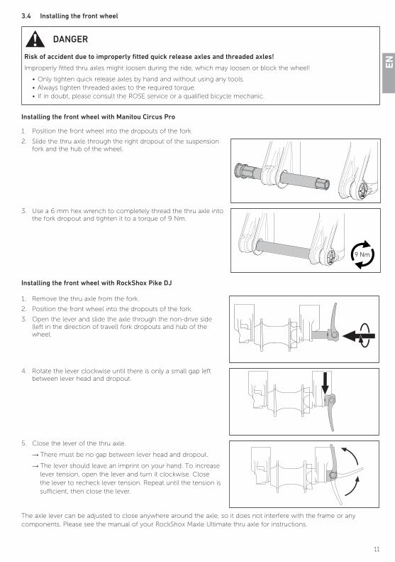
3.4 Installing the front wheel
DANGER
Risk of accident due to improperly fitted quick release axles and threaded axles!
Improperly fitted thru axles might loosen during the ride, which may loosen or block the wheel!
• Only tighten quick release axles by hand and without using any tools.• Always tighten threaded axles to the required torque.• If in doubt, please consult the ROSE service or a qualified bicycle mechanic.
Installing the front wheel with Manitou Circus Pro
1. Position the front wheel into the dropouts of the fork.
2. Slide the thru axle through the right dropout of the suspension fork and the hub of the wheel.
3. Use a 6 mm hex wrench to completely thread the thru axle into the fork dropout and tighten it to a torque of 9 Nm.
9 Nm
Installing the front wheel with RockShox Pike DJ
1. Remove the thru axle from the fork.
2. Position the front wheel into the dropouts of the fork.
3. Open the lever and slide the axle through the non-drive side (left in the direction of travel) fork dropouts and hub of the wheel.
4. Rotate the lever clockwise until there is only a small gap left between lever head and dropout.
5. Close the lever of the thru axle.
→ There must be no gap between lever head and dropout.
→ The lever should leave an imprint on your hand. To increase lever tension, open the lever and turn it clockwise. Close the lever to recheck lever tension. Repeat until the tension is sufficient, then close the lever.
The axle lever can be adjusted to close anywhere around the axle, so it does not interfere with the frame or any components. Please see the manual of your RockShox Maxle Ultimate thru axle for instructions.

EN
12
3.5 Adjusting saddle height and angle
DANGER
Extending the seat post past the minimum insertion mark may cause accidents or damages!
If the seat post is not inserted to the minimum insertion mark, it may break or damage the frame.
• The seat post must not be extended further than the limit mark.
• When cutting down the seat post, the original minimum insertion mark is no longer valid.
• Make sure to insert the seat post at least 10 cm into the frame.
min. 10 cm
The seat post and the inside of the seat tube are coated with grease during assembly. When re-installing the seat post at home for the first time, no additional treatment is required.
Adjusting the saddle height
1. Use a 4 mm hex wrench to open the saddle clamp.
2. Carefully slide the seat post into the seat tube until you have reached the desired height and align the saddle so it is perfectly straight.
→Do not lift the seat post any higher than the limit mark!
→ Stop inserting the seat post when any resistance is felt.
3. Use a 4 mm hex wrench to tighten the seat post clamp to a torque of 6 Nm.
6 Nm
Adjusting the angle of the saddle
1. Insert a 6 mm hex wrench into the slot-shaped opening on the saddle and turn the saddle clamp bolt a few turns to open it.
2. Tilt the saddle until you reach the desired angle.
→ Tilting the saddle slightly to the back may prove advantageous for some tricks. Test different saddle angles to find the perfect setup for your needs.
3. Use a 6 mm hex wrench to tighten the saddle clamp bolt to a torque of 10 to 12 Nm.
10 - 12 Nm

EN
13
3.6 Installing the pedals
One of the pedals has a right- and the other a left-hand thread. Most pedals have the letter “L” and “R” stamped on the end of the thread. Some pedals come with a groove in the flange of the left pedal. For more information see the manufacturer‘s manual.
1. Check if your bike was supplied with washers and slide both washers onto the pedal axles – if present.
2. Turn the left pedal counter-clockwise to screw it into the thread of the left crank arm and tighten the pedal to a torque of 35 Nm.
35 Nm
3. Turn the right pedal clockwise to screw it into the thread of the right crank arm and tighten the pedal to a torque of 35 Nm.
35 Nm

EN
14
3.7 Adjustable dropouts
The frame of THE BRUCE features adjustable dropouts allowing you to tension the chain without a chain tensioner.
Your bike was delivered with perfect chain tension. If you want to carry out maintenance works on your bicycle yourself, please follow the steps below to tension and release the chain.
1. Loosen the axle nuts (1, 2) of the adjustable dropouts on the right and left-hand side.
2. Thread in the tension adjusters (3) to tension the chain.
→When tightening the tension adjusters, the dropouts are moved backwards. The chain is tensioned.
→Make sure to tighten both adjusting bolts evenly.
→Only tighten the adjusting bolts until the screw heads are flush with the frame!
→Make sure the rear wheel is straight in the rear triangle.
→ Ensure the distance between the tyre and the right/left chainstay is the same.
3. If you want to release the chain, loosen the adjusting bolts (3).
→When loosening the adjusting bolts, the rear dropouts can be moved forwards. The chain is released.
→Make sure to loosen both adjusting bolts evenly.
→Only loosen the adjusting bolts until the adjustable dropouts are in contact with the front end stop.
→Make sure the rear wheel is straight in the rear triangle.
→ Ensure the distance between the tyre and the right/left chainstay is the same.
4. Tighten the axle nuts (1, 2) of the adjustable dropouts on the right and left side to a torque of 12 to 14 Nm.
5. Make sure the wheel is properly fitted and straight.
1
2
3
3
2

EN
15
4. Before and after your ride
4.1 Getting started for your first ride and getting used to your new bike
Make yourself familiar with the handling, brakes and suspension fork of your bike away from public roads. Do not forget to wear a helmet! Only slowly increase the difficulty of the terrain or manoeuvres.
Requirements:
• The bike is assembled in accordance with chapter “Bike assembly” (see “3. Bike assembly“ on page 9).
• All tasks from the chart “Before your ride” (see “4.2 Before your ride“ on page 15) have been carried out.
1. Break in the brake pads. Choose a road away from public roads and brake 20 to 30 from a speed of 30 km/h down to 5 km/h. You should brake as hard as possible without locking the wheel. Only then the brake can show its full braking power. Please additionally note the instructions of the brake manufacturer (see enclosed manual).
2. Check the functioning of the brake while riding.
As is usual for dirt bikes, your bike features a rear brake only. The rear brake is located on the right-hand side of the handlebar. Depending on the type of brake though, the brake lever can also be mounted on the left-hand side of the bar, if required.
If need be, a front brake can be retrofitted. The suspension fork and hub of the front wheel are already prepared for a front brake installation.
Many brakes offer the possibility to adjust bite point and lever reach. For this, please note the brake manufacturer’s instructions (see enclosed manual).
4.2 Before your ride
To make sure your bike is safe to ride, you should carry out certain tasks before your ride. This is for your own safety in particular, yet also for your riding pleasure. Nothing is more annoying than having a defect on a bike tour.
If there are any defects or flaws, your bike must be inspected by a qualified bicycle mechanic and repaired. Never ride with a defective bicycle!
Task/Check
Bef
ore
your
fir
st r
ide
Bef
ore
ever
y ri
de
Fram
e
Check the frame for damages and deformation.
→ There must be no damages.X X
Check whether all cables and hoses are in the cable clips and verify the tight fit of the clips.
→ All cables must fit firmly in the cable clips.X X
Susp
en
sio
n f
ork
Check the suspension fork for damages.
→ There must be no damages.
X X

EN
16
Wh
eels
Check that the wheels are straight. Lift the wheels one after the other and spin them.
→ The wheels must spin smoothly.
→ The wheels must run true, without moving up and down or from side to side.
→ The tyres must not rub against the frame.
X X
Check the wheels for play in the hubs. Lift the wheels one after the other and move the wheels to the side.
→ There must be no play.
X X
Check the freehub mechanism of the rear hub to ensure proper engagement.
Get on your bike, pull the front brake and put some power on the pedals while standing.
→ The power must be transferred to the rear wheel.
→ The freehub must not slip.
X X
Use a floor pump with pressure gauge to check the tyre pressure.
→ The tyre pressure must not fall below the minimum or exceed the maximum value recommended by the tyre and rim manufacturer.
X X
Check the tyres for damages and wear.
→ The tyres must not be damaged.
→ The tyres must not be worn so that the puncture protection belt or the carcass threads can be seen through the tread.
X X
Check whether the quick-release skewers and thru axles are properly attached. X X
Bra
kes
Check the bite point of the brake: Pull the brake lever while standing.
→ The bite point must be felt around half way down the brake lever travel.X X
Check the braking performance: Pull the brake lever while standing and push the bike backwards and forwards.
→ The rear wheel must lock when the brake lever is pulled.
X X
Check the brake pads for wear.
→ The brake pads with a metal backing plate must be at least 0,5 mm thick.X
Check the disc rotor for wear.
→Minimum thickness of brake rotors: Avid: 1,55 mm, Shimano: 1,5 mm.X
Check whether the brake hoses and connections are losing brake fluid and check them for defects.
→ Brake fluid must not escape at the connections.X X
Par
ts
Verify the tight fit of the stem: Stand in front of the bike with the front wheel between your knees. Try to turn handlebar left and right.
→ It should not be possible to turn the handlebar with normal force.
X X
Check the headset for play: Push the bike with the front wheel against a wall and slowly move the bike back and forth.
→ You should not notice any play.
X X
Verify the tight fit of the seat post: Stand behind your bike, hold the saddle with one hand and try to turn it left and right.
→ It should not be possible to turn the saddle or seat post.
X X
Make sure that all parts are tight.
→ Tighten the parts to the proper torque, if need be.X X
EN
17
4.3 After your ride
DANGER
Brake failure or reduced braking power due to dirty brake pads or disc rotors!
Brake pads and disc rotors must be free from lubricating substances such as grease, oil (also skin oil), wax, silicon etc.! Brake pads or disc rotors contaminated in this way must no longer be used!
4.3.1 Cleaning your bike
After your ride, you should clean your bike thoroughly using a soft cloth and clear water. Never use a pressure washer!
Stubborn dirt can be removed with a gentle cleaning agent. In this case, it is best to use washing up liquids for domestic needs. Pay attention to the notes and recommendations for use printed on the respective cleaner.
In addition, you will find numerous cleaning and care products for your bike on www.rosebikes.com.
After having cleaned your bike, you must lubricate the chain (see “4.3.2 Chain maintenance“ on page 17).
Pay particular attention to the suspension fork and make sure the area is clean. Dirt in this area may cause premature wear and thus a loss of performance of your suspension fork.
4.3.2 Chain maintenance
The bicycle chain is the most important part of the drivetrain system. An oily chain attracts dirt and thus accelerates wear.
Please regularly follow the steps below to ensure a long and reliable service life of your chain:
1. Clean the chain with an oil-soaked cloth.
2. Lubricate the chain using chain oil.
3. Wipe away excess oil with a dry, lint-free cloth.
4.3.3 Parking your bike
Bicycles should always be protected against falling down. Especially for lightweight bikes, it is often enough to fall down from a standing position to permanently damage frame or components.
4.4 After a crash
DANGER
Risk of accident due to damaged or broken components!
Crashes or exceptional stresses may cause unnoticed and invisible damages.
• Riding with damaged, bent or even torn parts is extremely dangerous.• After a fall, the bike and its components must be checked by the ROSE service or by a qualified bicycle
mechanic.• Never fix bent parts yourself, but replace them for your own safety.
Damages on aluminium parts are indicated by dents, cracks, deformations or discolorations. If you notice any sign of damage, the component or bike must no longer be used. When suspecting a damage, you should always consult the ROSE service or a qualified bicycle mechanic.

EN
18
5. Bike transport and storage
5.1 Transport by car
The best and safest way to transport your bike is by car. Here, your bike is perfectly protected from the elements and from theft.
When removing the wheels, make sure to fit a transport lock between the dropouts of the frame or fork.
5.2 Transport on a hitch or roof rack
Rims must be padded before fitting lashing straps or ratchet systems.
When transporting several bikes on one hitch or roof rack, please make sure that there is sufficient space or padding between the bikes.
Please also note the instructions of the bike rack manufacturer.
5.3 Bike storage
You should park your bike using an appropriate cycle stand which ideally only holds the rear wheel. Make sure to check the tyre pressure when the bike has stood for a long time. You should not park your bike for longer with no air in the tyres.
Another alternative for the secure storage of your bike is to hang it onto a hook that is padded or covered with plastic or rubber.
If you use a tubeless system, you should remove the sealant from the tyre when parking your bike longer than three months. Some sealants contain ingredients that increase corrosion and could thus damage the rim.
5.4 Bike shipping
Ship your bike in the same condition you’ve received it.
1. Secure or cover all loose or moving parts properly. Sharp or pointed components have to be wrapped additionally to make sure they won’t damage other parts of your bike and won’t tear through the outer packaging.
2. If your bike was delivered with a removed front wheel, the front wheel should also be removed for shipping now. Wrap the front wheel with a cardboard. This will also protect the handlebar and top tube of your bike.
3. If the wheels need to be removed, you must thread the thru axles into the dropouts.
4. Protect the top tube from damages through the handlebar by using appropriate material (e.g. foam tubing).

EN
19
6. Maintenance
Regular care and maintenance will prolong the life of your new bicycle. You should carry out easy cleaning, servicing and repair tasks yourself (see “4. Before and after your ride“ on page 15).
6.1 Bike servicing
DANGER
Risk of accident due to overdue maintenance and service!
When neglecting maintenance and servicing, worn components may cause accidents.
• The service works and intervals mentioned in this manual must be observed.• Service and maintenance works must be carried out by the ROSE service or a qualified bicycle mechanic.
A bike service includes a complete check of all components. Servicing is required after a specific period of time or after a certain amount of kilometres ridden, whichever comes first.
Service intervals and tasks
• 1. servicing after 500 to 1 000 km, six months after purchase date at the latest
• 2. servicing after 3 000 to 4 000 km or two years after purchase date
• 3. servicing after 5 000 to 7 000 km or three years after purchase date
Task 1. Servicing 2. Servicing 3. Servicing
Visual inspection of all components X X X
Check of all bearings and screw connections X X X
Check of spoke tension X X X
Wheel truing X X X
Adjustment of the brake X X X
Check of brake rotor for wear X X X
Check of chain, brake pads and tyres for wear and replacement, if necessary
X X

ROSE Bikes GmbH Schersweide 4 46395 Bocholt
Germany