overvoltage protection in railway abb
TRANSCRIPT

7/27/2019 Overvoltage Protection in Railway ABB
http://slidepdf.com/reader/full/overvoltage-protection-in-railway-abb 1/32
Overvoltage protectionMetal oxide surge arrestersin railway facilities
Ap pl ic at io n g ui de li ne s

7/27/2019 Overvoltage Protection in Railway ABB
http://slidepdf.com/reader/full/overvoltage-protection-in-railway-abb 2/32
First edition: June 2000Second edition, revised and expanded: October 2007
Thi rd ed ition: M ay 2011
All rights r eser ved. Nei ther the comp lete b rochurenor parts of it are to be copied, reproduced, transmittedin any way or translated into other languageswithout the express written consent of ABB Switzerland Ltd.
© ABB Switzerland Ltd.Division Surge Arresters, Wettingen/Switzerland

7/27/2019 Overvoltage Protection in Railway ABB
http://slidepdf.com/reader/full/overvoltage-protection-in-railway-abb 3/32
ForewordContinuous developmentand completion
The Application Guidelines Overvoltage Protection: Dimensioning, testing and
application of metal oxide surge arresters in railway facilities (rst edition June 2000)was much welcomed by our customers and other interested persons. The further
development of the products makes it necessary to revise and complete the
application guidelines. In the present application guide there are to be found not only
the adaptation to the newest standards but also devices for protection of persons
against too high contact voltage. The new structure is meant to bring more clarity.Bernhard Richter, responsible for product management, application of the overvoltage
protective devices and quality assurance in the Surge Arresters Division of ABB Switzerland Ltd., presents here in a precise form the technical bases of the
metal-oxide surge arresters and low voltage limiters, and their application in railway
facilities. Bernhard Richter is an active member in different working groups ofIEC (International Electrotechnical Commission), CENELEC (Comité Européen deNormalisation Electrotechnique), CIRED (Congrès International des RéseauxElectriques de Distribution) and CIGRÉ (Comité International des Grands RéseauxElectriques).Hopefully you, as a reader, will nd a lot of useful information in this new edition
of the brochure. We welcome amendments, suggestions and qualied hintsfor improving this brochure.
ABB Switzerland Ltd.
Wettingen, May 2011
7/27/2019 Overvoltage Protection in Railway ABB
http://slidepdf.com/reader/full/overvoltage-protection-in-railway-abb 4/324 Metal oxide surge arresters in railway facilities | Overvoltage protection
Foreword
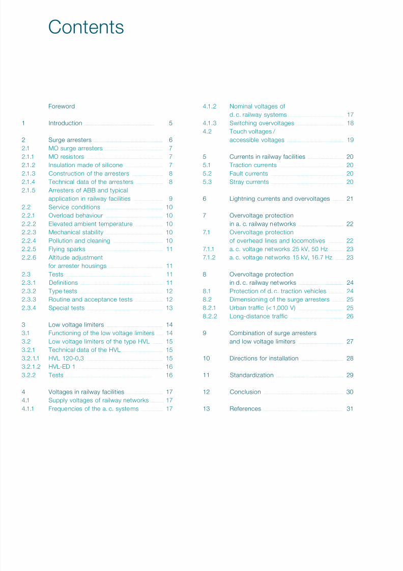
1 Introduction . . . . . . . . . . . . . . . . . . . . . . . . . . . . . . . . . . . . . . . . . . . . . . . . . . . . . . . . . . . . . . . . . . . . . . . . . . . 5
2 Surge arresters . . . . . . . . . . . . . . . . . . . . . . . . . . . . . . . . . . . . . . . . . . . . . . . . . . . . . . . . . . . . . . . . . . 62.1 MO surge arresters . . . . . . . . . . . . . . . . . . . . . . . . . . . . . . . . . . . . . . . . . . . . . . . . . . . . . . . . 72.1.1 MO resistors . . . . . . . . . . . . . . . . . . . . . . . . . . . . . . . . . . . . . . . . . . . . . . . . . . . . . . . . . . . . . . . . . . . . . . . . . 72.1.2 Insulation made of silicone . . . . . . . . . . . . . . . . . . . . . . . . . . . . . . . . . . . . 72.1.3 Construction of the arresters . . . . . . . . . . . . . . . . . . . . . . . . . . . . . . 82.1.4 Technical data of the arresters . . . . . . . . . . . . . . . . . . . . . . . . . . 82.1.5 Arresters of ABB and typical
application in railway facilities . . . . . . . . . . . . . . . . . . . . . . . . . . . . . 92.2 Service conditions . . . . . . . . . . . . . . . . . . . . . . . . . . . . . . . . . . . . . . . . . . . . . . . . . . . . . . . . . . 102.2.1 Overload behaviour . . . . . . . . . . . . . . . . . . . . . . . . . . . . . . . . . . . . . . . . . . . . . . . . . . . . . . . 102.2.2 Elevated ambient temperature . . . . . . . . . . . . . . . . . . . . . . . . . . . 102.2.3 Mechanical stability . . . . . . . . . . . . . . . . . . . . . . . . . . . . . . . . . . . . . . . . . . . . . . . . . . . . . . . 102.2.4 Pollution and cleaning . . . . . . . . . . . . . . . . . . . . . . . . . . . . . . . . . . . . . . . . . . . . . . . . 102.2.5 Flying sparks . . . . . . . . . . . . . . . . . . . . . . . . . . . . . . . . . . . . . . . . . . . . . . . . . . . . . . . . . . . . . . . . . . . . . . . . 112.2.6 Altitude adjustment
for arrester housings . . . . . . . . . . . . . . . . . . . . . . . . . . . . . . . . . . . . . . . . . . . . . . . . . . . . 112.3 Tests . . . . . . . . . . . . . . . . . . . . . . . . . . . . . . . . . . . . . . . . . . . . . . . . . . . . . . . . . . . . . . . . . . . . . . . . . . . . . . . . . . . . . . . . . . . . . 112.3.1 Definitions . . . . . . . . . . . . . . . . . . . . . . . . . . . . . . . . . . . . . . . . . . . . . . . . . . . . . . . . . . . . . . . . . . . . . . . . . . . . . . . 112.3.2 Type tests . . . . . . . . . . . . . . . . . . . . . . . . . . . . . . . . . . . . . . . . . . . . . . . . . . . . . . . . . . . . . . . . . . . . . . . . . . . . . . . . 12
2.3.3 Routine and acceptance tests . . . . . . . . . . . . . . . . . . . . . . . . . . .
122.3.4 Special tests . . . . . . . . . . . . . . . . . . . . . . . . . . . . . . . . . . . . . . . . . . . . . . . . . . . . . . . . . . . . . . . . . . . . . . . . . 13
3 Low voltage limiters . . . . . . . . . . . . . . . . . . . . . . . . . . . . . . . . . . . . . . . . . . . . . . . . . . . . . . 143.1 Functioning of the low voltage limiters . . . . . . . 143.2 Low voltage limiters of the type HVL . . . . . . . . . . . 153.2.1 Technical data of the HVL . . . . . . . . . . . . . . . . . . . . . . . . . . . . . . . . . . . . . . . 153.2.1.1 HVL 120-0,3 . . . . . . . . . . . . . . . . . . . . . . . . . . . . . . . . . . . . . . . . . . . . . . . . . . . . . . . . . . . . . . . . . . . . . . . . . 153.2.1.2 HVL-ED 1 . . . . . . . . . . . . . . . . . . . . . . . . . . . . . . . . . . . . . . . . . . . . . . . . . . . . . . . . . . . . . . . . . . . . . . . . . . . . . . . . . 163.2.2 Tests . . . . . . . . . . . . . . . . . . . . . . . . . . . . . . . . . . . . . . . . . . . . . . . . . . . . . . . . . . . . . . . . . . . . . . . . . . . . . . . . . . . . . . . . . . . . . 16
4 Voltages in railway facilities . . . . . . . . . . . . . . . . . . . . . . . . . . . . . . . . . . . 17
4.1 Supply voltages of railway networks . . . . . . . . . . . .
174.1.1 Frequencies of the a. c. systems . . . . . . . . . . . . . . . . . . . . . . 17
4.1.2 Nominal voltages ofd. c. railway systems . . . . . . . . . . . . . . . . . . . . . . . . . . . . . . . . . . . . . . . . . . . . . . . . . . . . . 17
4.1.3 Switching overvoltages . . . . . . . . . . . . . . . . . . . . . . . . . . . . . . . . . . . . . . . . . . . . . 184.2 Touch voltages /
accessible voltages . . . . . . . . . . . . . . . . . . . . . . . . . . . . . . . . . . . . . . . . . . . . . . . . . . . . . . . 19
5 Currents in railway facilities . . . . . . . . . . . . . . . . . . . . . . . . . . . . . . . . . . . 205.1 Traction currents . . . . . . . . . . . . . . . . . . . . . . . . . . . . . . . . . . . . . . . . . . . . . . . . . . . . . . . . . . . . . . 205.2 Fault currents . . . . . . . . . . . . . . . . . . . . . . . . . . . . . . . . . . . . . . . . . . . . . . . . . . . . . . . . . . . . . . . . . . . . . . 205.3 Stray currents . . . . . . . . . . . . . . . . . . . . . . . . . . . . . . . . . . . . . . . . . . . . . . . . . . . . . . . . . . . . . . . . . . . . . . 20
6 Lightning currents and overvoltages . . . . . . . . . . .
21
7 Overvoltage protectionin a. c. railway networks . . . . . . . . . . . . . . . . . . . . . . . . . . . . . . . . . . . . . . . . . . . . 22
7.1 Overvoltage protectionof overhead lines and locomotives . . . . . . . . . . . . . . . . 22
7.1.1 a. c. voltage networks 25 kV, 50 Hz . . . . . . . . . . . . . . 237.1.2 a. c. voltage networks 15 kV, 16.7 Hz . . . . . . . . . 23
8 Overvoltage protectionin d. c. railway networks . . . . . . . . . . . . . . . . . . . . . . . . . . . . . . . . . . . . . . . . . . . . 24
8.1 Protection of d. c. traction vehicles . . . . . . . . . . . . . . . 24
8.2 Dimensioning of the surge arresters . . . . . . . . . . . .
258.2.1 Urban traffic (< 1,000 V) . . . . . . . . . . . . . . . . . . . . . . . . . . . . . . . . . . . . . . . . . . . . 258.2.2 Long-distance traffic . . . . . . . . . . . . . . . . . . . . . . . . . . . . . . . . . . . . . . . . . . . . . . . . . . . . 26
9 Combination of surge arrestersand low voltage limiters . . . . . . . . . . . . . . . . . . . . . . . . . . . . . . . . . . . . . . . . . . . . 27
10 Directions for installation . . . . . . . . . . . . . . . . . . . . . . . . . . . . . . . . . . . . . . . . . 28
11 Standardization . . . . . . . . . . . . . . . . . . . . . . . . . . . . . . . . . . . . . . . . . . . . . . . . . . . . . . . . . . . . . . . . . 29
12 Conclusion . . . . . . . . . . . . . . . . . . . . . . . . . . . . . . . . . . . . . . . . . . . . . . . . . . . . . . . . . . . . . . . . . . . . . . . . . . . . . 30
13 References . . . . . . . . . . . . . . . . . . . . . . . . . . . . . . . . . . . . . . . . . . . . . . . . . . . . . . . . . . . . . . . . . . . . . . . . . . . . . 31
Contents

7/27/2019 Overvoltage Protection in Railway ABB
http://slidepdf.com/reader/full/overvoltage-protection-in-railway-abb 5/32 Overvoltage protection | Metal oxide surge arresters in railway facilities 5
The overvol tage protection of the electr ica l energy supplyinstallations of railway facilities has an increasing importancenowadays, not only for railways which are supplied witha. c. voltage but also increasingly for d. c. voltage railways.
The long-distance rai lway system is electri fied with 3 kVd. c. voltage on over 70,000 km ra ils (in year 2000,that means about 38 % of the total length of the rails of theelectrical railways) and with 1.5 kV d. c. voltage on morethan 20,000 km (about 11 %). That means that about half ofthe world-wide railway length of the long-distance traffic isoperated with direct current. The length of the electrified rails
by the outer suburban service, including local trains, whichoperate wi th a d. c. voltage under 1,000 V, is about25,000 km. These figures show the extent of the d. c. voltagesystems in railways and also the importance of an optimalovervoltage protection which is adjusted to the specificdemands of the d. c. voltage railways. The appl ication and dimens ion ing of metal oxide surgearresters (MO surge arresters) without spark gaps in alter-nating current networks with 50 Hz and 16.7 Hz of the railwaysupply is not very different from the one of the generalenergy supply. On the other hand the dimensioning and theload of the MO surge arresters in d. c. railway facilities
have not been extensivel y dealt with unt il now. Moreover,the modern MO surge arresters without spark gaps andwith silicon insulation make it possible to develop solutionsfor special applications. The fact that the electr ica l ra ilways expand very rapidly,like for instance in China, India and in urban agglomerations,shows the necessity to develop new and more optimalovervoltage protection devices.Overvoltages in electrical supply networks result from theeffects of lightning strokes and switching actions andcannot be avoided. They endanger the electrical equipment,because, due to economical reasons, the voltage with-
stand capability of the insulation cannot be designed forall possible cases. Therefore, an economical and reliableservice calls for extensive protection of the electricalequipment against unacceptable overvoltages. In factthis applies to all networks of the energy supply.We will shortly present here different kinds of overvoltageand the possibility of reducing them. For general informationyou may use the Application Guidelines OvervoltageProtection: Dimensioning, testing and application of metaloxide surge arresters in medium voltage networks [1] and further literature.
We only want to mention here that lightning strokes arethe most dangerous threat for railway networks. That is whyit is necessary to reduce the overvoltage to a safe valuethrough appropriate protection. MO surge arresters withoutspark gaps give outstanding protection in this situation.In this brochure the technical outdated protection applianceslike arcing horns and spark gap arresters, as well as surgearresters in porcelain housings, are not dealt with any more.In some applications, for instance on overland lines inregions with high risks of lightning and on bridges, partsof the total lightning current may stress the MO surge
arrester directly due to direct or nearby lightning. Therefore,lightning current parameters, resulting overvoltages, andenergy stresses need to be considered.In order to avoid the stray current corrosion the rails ind. c. railways are mostly insulated against ear th. In case ofa defect (for instance the breaking of the overhead line)or some operational cases, inadmissible contact voltagescan appear which may be dangerous for persons. The newlydesigned protection devices, which protect not only theappliances against overvoltages but also persons againstcontact voltages, make it possible to develop new protectionconcepts.
1 Introduction

7/27/2019 Overvoltage Protection in Railway ABB
http://slidepdf.com/reader/full/overvoltage-protection-in-railway-abb 6/326 Metal oxide surge arresters in railway facilities | Overvoltage protection
The so-cal led “conventional” surge arresters were almostexclusively installed in networks of the electrical energysupply until the middle of the eighth decade of the lastcentury. They consist of a series connection of SiC resistorsand spark gaps, which are placed in porcelain housing,and are generally called “spark gap arresters”.Spark gap arresters have a couple of disadvantages: They reduce overvoltages only when the breakdown vol tageof the spark gaps is achieved. The breakdown voltage ofthe spark gaps depends on the steepness of the incomingvoltage which results in a bad protection especially for steep
overvoltages.If the outside insulation of the arrester is polluted, thepotential distribution can shift along the active part, and thiscan cause unwanted sparkover in the spark gaps, whichin the end may destroy the arrester.If spark gap arresters are connected in parallel only onearrester switches on during an overvoltage. That is thearrester that has the lowest response voltage. This arresterreduces the overvoltage to a value below that of the spark-over voltage of the other parallel arresters, and in this wayit prevents the sparkover of the other arresters. Thereforeit is not possible to distribute the energy of the surge among
more spark gap arresters which are connected in parallel.In the spark gap arresters the follow current flows three timeslonger with 16.7 Hz than with 50 Hz which overloads thespark gap arrester having the same continuous voltage asfor 50 Hz. In the past, spark gap arresters, which were usedin networks of 16.7 Hz, had an inconvenient higher voltagethan the arresters of 50 Hz, and implicitly a worse protectionlevel. The problem of using spark gap arresters in d. c. networkslies especially in the fact that the arc that is producedthrough a sparkover has to be extinguished.
If an arrester with porcelain housing is overloaded it isalways possible that the porcelain insulator cracks andthat the porcelain pieces that fall down can cause injuries. Arc ing horns have no insulation housing and therefore thei rdisadvantage lies in the fact that their function very stronglydepends on their state and the environment condition(erosion of the electrodes, humidity, ice, pollution, foreignparticles, animals, etc.). It is also possible that the d. c. arc,once arisen, cannot be extinguished any more, becausethere is no natural current zero.
2 Surge arresters
Table 1: Correlation of typical MO resistors to the line discharge
classes. The given energy relates to the operating duty test,
and is the energy injected to the arrester before proving the thermal
stability of the arrester under applied continuous operating voltage.
Line discharge class
acc. IEC/EN 60099-4 1 2 2 3 4 5
Diameter of
MO resis tor in mm 38 42 47 62 75 108Rectangular wave,
2 ms, in A 250 350 550 1,000 1,350 2,000
Energy absorption
in kJ/kV U c 3.6 3.5 5.5 9.0 13.3 19.8

7/27/2019 Overvoltage Protection in Railway ABB
http://slidepdf.com/reader/full/overvoltage-protection-in-railway-abb 7/32 Overvoltage protection | Metal oxide surge arresters in railway facilities 7
2.1 MO surge arresters
There are two essentia l improvements in the arrestertechnology nowadays compared to the spark gap arres ter.One of them is the metal-oxide resistor that replaced theseries connections of spark gaps and SiC resistors, andthe other one is the replacement of the porcelain housingthrough polymeric material.
2.1.1 MO resis tors
The MO resistors make up the act ive par t of the MO surgearrester. They are made of different metal oxides in powderform which are compressed and sintered in the form of roundblocks [2]. The diameters of the MO resistors of ABB Switzer-land Ltd., made for all the networks of the electrical energysupply and for special applications, lie between 38 mm and108 mm. The height of the MO resistors is typically between1 mm and 46 mm. The diameter of the MO resistors deter-mines the carrying capacity of the current, the height ofthe MO resistors (or resistor stack) determines the voltagein continuous operation, and the volume of the blocks theenergy capacity.
The contact areas of the MO res istors are metall ised upto the edge of the block with soft aluminium, the surface ofthe housing is coated with glass. In this way the MO materialof the MO resistors of ABB Switzerland Ltd. is completelycovered. Figure 1 shows a selection of MO resistors. The diameter of the MO res istors correlates with the linedischarge classes corresponding to IEC/EN 60099-4,as shown in Table 1 [3]. As this specification deals onlywith a. c. voltage networks with voltage rated ≥ 3 kV, the testsand demands that are mentioned here can only partiallybe applied to the d. c. voltage networks.
2.1.2 Insulation made of silicon
Silicon is an excellent insulation material as compared todifferent insulation materials like porcelain, glass and othersynthetic materials like EPDM. The advantageous propertiesof silicon for the insulation of MO surge arresters are:• hydrophobicity of the material• self-extinguishing behaviour• no toxic elements• mechanical unbreakability• small weight
Figure 1: MO resistors (selection) manufactured by ABB.

7/27/2019 Overvoltage Protection in Railway ABB
http://slidepdf.com/reader/full/overvoltage-protection-in-railway-abb 8/328 Metal oxide surge arresters in railway facilities | Overvoltage protection
2.1.3 Construction of the arresters
The patented principle of construct ion of the ABB arresterswith silicon direct-moulding consists of two electrodes whichare connected to one another through two or more glass-fibre reinforced elements. It results a hard cage or frame,which guarantees the mechanical strength. The MO resistorsare arranged inside this frame. Additional metal cylinderswith the same diameter as the MO resistors fill the insidecompletely, forming in this way a uniformly round active part. The MO blocks are pressed together with a bol t in thecentre of the lower electrode. The bolt is secured in the end
position, providing in this way each arrester with the samecontact pressure. The active part is placed into a form andcompletely moulded in silicon. As a result the surge arrester,which is completely sealed and tight, has no void inside.Figure 2 shows a MO surge arrester of type POLIM-H,which was manufactured according to this technique, beforeand after being moulded in silicon. The flexible methodof construction (modular concept) provides the possibilityof changing the form of the arrester in order to fit eachnecessity.
2.1.4 Technical data of the arresters
The demands on the arresters depend on the operationalconditions and the type of the electrical equipment to beprotected. For the railway facilities, which have differentvoltage networks and special demands, both electrical andmechanical, ABB offers a selection of different types ofMO surge arresters. The safety and the ecological aspectare especially taken into consideration with all the arresters. Table 2 presents main technical data of the arresters,applicable for railway facilities. Railway facilities are servicedwith both d. c. and a. c. systems and the arrester t ypes
are operationa l for both d. c. and a. c. voltage networks. Therefore the definit ions and data are sli ght ly dif ferent whichrequires a splitting of the table.
Ar res ter type In Ures / Uc Ihc E / Uc Rectangula r wave MPSL* Torsion Vertical load
a. c. systems kA kA kJ/kV A ( t = 2 ms) N Nm N
MWK / MWD 10 3.07 100 5.5 550 850 68 1,200POLIM- I 10 3.07 100 5.5 550 3,500 100 2,000
POLIM-S 10 3.0 100 9.0 1,000 5,700 100 3,000
POLIM-H 20 3.19 100 13.3 1,350 8,000 100 4,000
Ar res ter type In Ures / Uc, dc Ihc E / Uc, dc Rectangula r wave MPSL* Torsion Vertical load
d. c. systems kA kA kJ/kV A ( t = 2 ms) N Nm N
POLIM-C..ID 10 3.2 100 4.3 550 –/–** –/– –/–
POLIM-C..ND 10 3.2 100 4.3 550 690 50 1,000
POLIM-H..SD 20 2.7 100 10.5 1,350 2,500 50 1,000
POLIM-H..ND 20 2.7 100 10.5 1,350 8,000 100 4,000
POLIM-X..ND 20 2.7 200 21.0 2,700 16,000 100 1,500
POLIM-R..-1 ND 20 2.7 100 10.5 1,350 –/– –/– –/–
POLIM-R..-2 ND 20 2.4 200 19.0 2,400 –/– –/– –/–POLIM- ID 40 3.0 400 37.8 4,860 –/– –/– –/–
* Maximum permissi ble service load. The MPSL is, accordin g to the denition, the force which can be applied on the highest arrester of an arrester seriesduring 60 s until 90 s, wi thout resultin g in a permanent de ection more tha n 5 % of its height.
** Arresters without information about mechanical data are not allowed to be loaded with bigger mechanical forces at the high voltage connection.Information about the mechanical loading capacity is to be received from the manufacturer.
Table 2: Main technical data of ABB arresters which are used in railway facilities.
Figure 2: MO surge arrester type POLIM-H..ND.
Left: active part before moulding. Middle: scheme of design.
Right: complete arrester with base plate and terminal.

7/27/2019 Overvoltage Protection in Railway ABB
http://slidepdf.com/reader/full/overvoltage-protection-in-railway-abb 9/32 Overvoltage protection | Metal oxide surge arresters in railway facilities 9
2.1.5 Arresters of ABB and typical application
in railway facilities
The fo llowing pictures show the actual por tfo lio ofMO surge arresters of ABB for application in d. c. anda. c. railway systems. Further information can be found atwww.abb.com/arrestersonline
POLIM 4,5 ID
Special surge arrester for d. c. railwayinstallations with U n = 3 kV.
Extremely high energy absorption capabilitywith excellent protection level.For indoor applications only.
POLIM-X..ND
Very power ful surge arrester ford. c. railway networks up to U n = 3 kV.For areas with high lightning activitiesand danger of direct lightning.
POLIM-H..ND
For use in d. c. railway installations
up to U n = 3 kV. Protection of e lectriclocomotives and substations. Very ruggeddesign, especially developed for railwayapplications.
POLIM-H..SD
For use in d. c. railway systemsup to U n = 3 kV. Thanks to its compactdesign it is particularly suitable for usein substations and trolleys.
POLIM-R..1/2 NDFor special applications in d. c. networks. Very high energy absorption capabil ity withsimultaneously very good protection level.
POLIM-C..ND
Protection of d. c. installations includingrailway systems, transformers and motors.
POLIM-C..ID
For special applications in medium voltagesystems, for motor and cable sheathprotection, also for d. c. applications.
POLIM-H..N
Surge arrester with particularly high
mechanical and electrical strength.
Recommended for use in railway installa-
tions and on rolling stock. Typical stationclass arrester for a. c. systems with
f = 50 Hz and 16.7 Hz.
POLIM-S..N
Surge arrester with high energy absorptioncapability and good protection level inrugged mechanical construction.For installation in a. c. systems withf = 50 Hz and 16.7 Hz.
POLIM-I..N
Suitable for the protection of medium
voltage transformers and cable installationsas well as railway instal lations. Typicalintermediate surge arrester in ruggedmechanical construction. For use ina. c. systems with f = 50 Hz and 16.7 Hz.

7/27/2019 Overvoltage Protection in Railway ABB
http://slidepdf.com/reader/full/overvoltage-protection-in-railway-abb 10/3210 Metal oxide surge arresters in railway facilities | Overvoltage protection
2.2 Service conditions
The service l ife of the arresters cou ld be of about 30 yearsunder normal operating conditions if they are properlydesigned for the respective system voltage and forthe expected electrical and mechanical loads. The normalservice conditions for the MO surge arresters are to befound in [3]:• ambient temperatu re −40 °C to +40 °C• solar radiation 1.1 kW/m2
• altitude up to 1,000 m above sea level
• frequency of a. c. voltage between 48 Hz and 62 Hz• power frequency voltage at the arrester connectionsnot higher than the continuous operating voltage U c of the arrester
Al l the arresters of ABB fulfi l or even exceed these ser viceconditions. Some special cases are discussed in thefollowing chapter.
2.2.1 Overload behaviour
Any arrester can be over loaded. The causes can be
extremely high lightning currents or a so-called voltagetransition, a short circuit between two different voltagelevels. In all these situations there is in fact an energy over-loading. In such a case of overloading the MO resistorseither sparkover or break down and create as a rulea permanent short circuit. An arc results inside the arresterand the current in this arc is defined by the short circuitpower of the network. With the ABB arresters with siliconhousing there is no danger of explosion or shatteringin case of an overload. There is no air space between theactive part of the arrester and its silicon insulation, thusthere is no place for the pressure to build up. The occurring
arc (or sparks) escapes the silicon insulation immediatelyas it occurs and so it is free. Because of their specialconstruction the arresters are safe against explosion upto the highest short circuit currents.
2.2.2 Elevated ambient temperature
The ABB arresters (a . c. and d. c. voltage) are gua ranteed tofunction flawlessly up to 40 °C ambient temperature. Thisalso includes the maximum solar radiation of 1.1 kW/m 2 foroutdoor arresters. If there are heat sources in the vicinity ofthe arrester, the increase of the ambient temperature mustbe taken into account, and the value of U c increased if nec-essary. If the ambient temperature exceeds 40 °C, U c mustbe increased by 2 %, for every 5 K of temperature elevation.
This correction is possib le up to maximum 80 °C ambienttemperature.
2.2.3 Mechanical stability
The arresters of ABB are operationall y re liable even in areasof high earthquake activity. The arresters may partially takeon the support function or, as line arresters, they may havethe function of suspension insulators. By such operationalsituations it is necessary to inform the manufacturer. Thevalues given in Table 2 are not to be exceeded. The arrestertypes which are to be applied on rolling material are deliveredwith a reinforced base plate and are tested acc. [4] undervibration and shock conditions.
2.2.4 Pollution and cleaning
Silicon is the best insulating material in case of pollution. This is mainly because the material is water-repell ent (hydro-phobic). Silicon arresters behave more favourably underconditions of heavy pollution than porcelain housed arrestersor other polymer insulation materials.Decisive for the long-term behaviour under pollution ofan insulation made out of a polymeric material is the dynamicbehaviour of the hydrophobicity, which is originally almostalways very good [11].
Depending on the material a loss of hydrophobicity can bepermanent or temporary. The silicon in contrast to otherpolymeric materials is able to gain back the hydrophobicityafter losing it for a while. Arresters which are appl ied on rol ling materia l and areregularly washed are not affected in any way. Environmentallysafe cleaning agents do affect neither the arrester functionnor the properties of the insulation.

7/27/2019 Overvoltage Protection in Railway ABB
http://slidepdf.com/reader/full/overvoltage-protection-in-railway-abb 11/32 Overvoltage protection | Metal oxide surge arresters in railway facilities 11
2.2.5 Flying sparks
The silicone used in the described ABB arresters is ahardly inflammable and self-extinguishing material. Testshave shown that blazing hot particles, which emerge bythe de-contacting of the pantograph or by braking,do not negatively affect the silicon housing of the arrester. There is no danger that the arrester can be igni ted bythe sparks, or that the insulation resistance of the housingmay be decreased through humidity or rain because ofthe particles that adhere to the surface.
2.2.6 Altitude adjustment for arrester housings
The ABB arresters can be used without any housing adjust-ment up to a height of 1,800 m above sea level. At higheraltitudes the air density is so low that the withstand voltageof the arrester housing (external flashover) is not suf ficientany longer. In this case the unaltered active part ofthe arrester (same protection level) must be placed in anelongated housing with a longer flashover distance.
As a reference point one may consider that for every 1,000 mover 1,800 m above sea level the flashover distance mustbe increased by 12 %. For example, at an alti tude of 3,300 m
above sea level the flashover distance of the housing mustbe 18 % longer than that of a standard arrester. It is neces-sary to mention that the flashover distances of arrestersfor lower voltage levels are relatively large initially, exceedingthe minimum requirements of the withstand voltage. Thus, it should be checked for each sing le case whether thenormal housing possesses the sufficient withstand voltagefor the application in higher altitudes.
2.3 Tests
The requests and tests for MO surge arresters in a. c. rai lwayfacilities are not different from the ones for arresters in net-works of the electric power supply (refer to the bibliographyno. [1] and [3]). The additional tests, which are necessaryespecially for the railway facilities, are shown in the followingchapters. The requests and tests for arresters in fixed d. c. railwayinstallations are to be found in the standard EN 50123-5 [12]. The most important of them and especial ly the par tia lly
different definitions and test procedures for the railwayapplication [3] will be explained shortly in the following lines. Tests with l ightning currents, or with stresses equivalentto lightning currents, are under consideration in the stan-dardisation working groups. For the time being such testshave to be agreed upon between manufacturer and user.
2.3.1 Definitions (See also chapter 4)
Rated voltage (U r) The maximum d. c. voltage value between termina ls which
the surge arrester has to withstand in the operating duty test. This vol tage corresponds to the temporary vo ltage increaseU max2 acc. EN 50163 [5], which is allowed to appear formaximum 5 minutes.
Maximum continuous operating voltage of the arrester (U c) The highest voltage which may be appl ied unl imi ted betweenthe terminals of the arrester.
Nominal discharge current of an arrester (In)Peak value of the lightning current corresponding toIEC 60099-4. The nominal discharge current is used for
classifying the arresters.
Protective voltage level of the arrester (U res ) The highest residual vol tage at the nomina l di schargecurrent In. The re lat ion U res / U c shows the protection level of the arrester. The smal ler the re lat ion U res / U c, the better is the protectioncharacteristic of the arrester.
7/27/2019 Overvoltage Protection in Railway ABB
http://slidepdf.com/reader/full/overvoltage-protection-in-railway-abb 12/3212 Metal oxide surge arresters in railway facilities | Overvoltage protection
2.3.2 Type tests
The type tests are tests which are carried out only onceto show that a special arrester type operates properly. The type tests for MO surge arresters without spark gaps,which are used in a. c. voltage networks, are describedin the standard IEC/EN 60099-4. In EN 50123-5 there isthe description of the type tests for MO surge arresters ind. c. systems, fixed installations.
The fo llowing t ype tests are to be carr ied out:• testing of the insulation withstand voltage of the housing
• testing of the residual voltage– with steep current impulse– with lightning current impulse– with switching current impulse
• testing with rectangular current waves• operating duty test (operating duty test with high current
impulse)• d. c. voltage versus time character istic• tightness test• proof of the pressure relief / overload test (by agreement
between customer and manufacturer)
The tests are similar to the ones for the MO surge arresterswhich are used in a. c. networks. Only the procedureof the operating duty test is different from the one of theMO surge arresters in a. c. networks. This is why we describehere minutely only the operating duty test and the ageing testfor the MO resistors applied in d. c. voltage systems.
Operating duty test• measuring of the residual voltage at In
• conditioning (4 groups of 5 applications of In,superimposed on 1.2 U c)
• high current impulse 4/10 μs• heating in the oven up to 60 °C• high current impulse 4/10 μs• rated voltage U r for 300 s• continuous voltage U c for 1,800 s• measuring of the residual voltage at In
• visual inspection
In the current EN 50123-5 it is pointed out that if thereare not sufficient direct current sources for this test, it ispossible to carr y out the test with a. c. voltage (alternativeprocedures), by agreement between the manufacturerand the customer.
Accele rated ageing test This test has to show that the power losses of the arresterin the network under applied continuous operating voltagedo not increase with time. In order to demonstrate this,the power losses are measured in a time-accelerated ageing
test under increased load. It is decisively important thatthis test should be carried out with d. c. voltage. It is knownthat MO material, which has a long-time stability with thealternating voltage load, is not necessarily long-time stablewith direct voltage load. The results of ageing tests whichare carried out with a. c. voltage are not transferable tothe application in d. c. voltage networks. Al l ABB MO res istors which are instal led in arresters ford. c. voltage networks fulfil the most strictly demandstowards the long-time stabil ity under d. c. voltage load.
2.3.3 Routine and acceptance tests The routine tests are carried out cor responding to IEC/EN60099-4, and they are not different from the tests for arrest-ers which are used in a. c. voltage networks of the generalelectrical energy supply. Arresters for d. c. systems andfor 16.7 Hz systems are normally tested in the routine testwith equivalent 50 Hz voltages and currents. Acceptance tests are in principle to be agreed upon bythe manufacturer and the customer.

7/27/2019 Overvoltage Protection in Railway ABB
http://slidepdf.com/reader/full/overvoltage-protection-in-railway-abb 13/32 Overvoltage protection | Meta l oxide surge arresters in railway facilities 13
2.3.4 Special tests
The present EN 50123-5 relate to EN 60099-4, 1993 (orIEC 60099-4, 1991) with regard to the tests for MO surgearresters. This edition describes only the demands andthe tests for MO surge arresters with porcelain housing ina. c. networks. That is why different tests are only restric tivelyapplicable to arresters with insulation made out of polymericmaterials, or are still under discussion. The demands and the tests for the arresters with insu lat ionmade out of polymeric materials described in the latestedition of IEC 60099-4, 2006, will be taken into consideration
in the revised edition of EN 50123-5.During the development of the MO surge arresters withpolymeric insulation there were carried out all kind of tests. These specia l tests and deve lopment tests are here shor tlymentioned. For more information please refer to [1].
Weather-ageing testPollution and ageing tests under extreme weather conditions,which are carried out on complete arresters, with longduration stress (1,000 h) or cyclical load (total 5,000 h) haveto inform about the behaviour of the arrester in the network.
The cycl ical 5,000 h test is the most meaningful test for
the critical examination of the long-term behaviour ofthe dynamic hydrophobicity (the return of the hydrophobicityafter a temporary loss).
Test with high air humidi ty This long-time test over several years was car ried out atthe Technical University of Tampere in Finland as a researchproject. During all the time the test samples were in a climaticchamber under applied voltage in a relative air humidityof 95 % up to 100 % and a temperature of 30 °C up to 35 °C.
Cold and icing testsIn order to test the behaviour of the arresters at very lowtemperatures, tests were carried out in air up to −60 °Cand icing tests up to −40 °C.
UV tests The positi ve behav iour of the used materia l (s ili con) wasshown in long-term tests in outdoor test fields and in labsunder strong UV radiation for more than 1,000 h.
Sparking Through the jumping of the pantographs and dur ing brakingit is possible that hot rubbed-off particles may arise. Thesemay spray as sparks on the nearby arrester. In order to dem-onstrate that the silicon insulation is insensitive to this kind ofstress, the arresters were exposed to a forced spark stress.
Af terwards the resistance of the insulation was tested.
Overload testsIn the new IEC 60099-4, 2006 there are methods describedto proof the short circuit behaviour of different arresterdesigns. The arresters, depending on their type and rating,are tested with short circuit a. c. currents up to 63 kA, 0.2 s.Short circuit currents in d. c. railway systems can reach upto 45 kA. Consequently, short circuit tests have to be carriedout with d. c. currents with reference to IEC 60099-4, 2006.
Vibration and shock tests
MO surge arresters on rolling material are exposed to specialmechanical stress. That is why all the arresters which areused on rolling material are delivered with a reinforced baseplate for the appliance on locomotives. The arresters onthese base plates were exposed to a vibration and shock testaccording to IEC 61373 [4].

7/27/2019 Overvoltage Protection in Railway ABB
http://slidepdf.com/reader/full/overvoltage-protection-in-railway-abb 14/3214 Metal oxide surge arresters in railway facilities | Overvoltage protection
Low voltage limiters are protective devices that are used infixed installations of d. c. traction systems in order to diminishinadmissible high potential differences between differentearthed metallic parts, especially between the rails andearthed metallic parts. They are therefore protective againsttoo high touch voltage. As a rule the rai ls are not direct ly ear thed in order to avoidstray currents in d. c. traction systems. In case that anoverhead line breaks down (falling down of the conductor)an inadmissible high touch voltage may occur between therails and the nearby metallic objects (masts, railings, etc.).
Even the normal train operation can lead to inadmissibletouch voltages, as for instance during maintenance work inthe stations. In these cases the low voltage limiters protectpersons effectively.Low voltage limiters are not to be used to protect installa-tions against lightning and switching overvoltages.
3.1 Functioning of the low voltage limiters
The operationa l pr inc iple of the commercia lly avai lab le lowvoltage limiters consists of two electrodes made of metal,which face one another and are insulated against each other. They produce a permanent short circui t through fusing i f thevoltage gets beyond a certain maximum value. The insulationconsists mainly of a thin ring made out of an insulatingmaterial. In another concept there is a gas discharge tubeused as insulation; it also gives a certain protection againstimpulse overvoltages.
Almost a ll commercia lly avai lab le low voltage l imi ters pro-duce a non-reversible short circuit between two potentialsat the moment of the sparkover. The low voltage limiters which are placed along the rai lsand in the stations are stressed with overvoltages comingfrom lightning or switching. Investigations have shownthat most commercial low voltage limiters go in the shortcircuit state after being stressed with lightning overvoltage.
3 Low voltage limiters
Figure 3: Principle circuitry of the bipolar low voltage limiter
HVL 120-0,3.
trigger
electronic
U
varistor
thyristor
Figure 4: Function of HVL. Overvoltages, for instance generated
by lightning, are limited by the MO resistor. In this short time frame
the thyristors are not fired (above). In case of failures in the system,
e. g. braking of overhead line with contact to the rails, the voltage
rise is relati vely slow. If the voltage reaches a given value the
thyristors are fired, and the current commutates from the MO resistor
to the conducting thyristor (below). The voltage at the HVL is almost
zero, the total current is flowing through the thyristor. If the current
becomes zero (e. g. clearing of the fault) the thyristo r extinguishes
and becomes high ohmic again, as in the original state.
lightning
(µs)
short circuit (s to m)
protection against overvoltage
protection against touch voltage
I
U
I
U
t
t

7/27/2019 Overvoltage Protection in Railway ABB
http://slidepdf.com/reader/full/overvoltage-protection-in-railway-abb 15/32 Overvoltage protection | Metal oxide surge arresters in railway facilities 15
3.2 Low voltage limiters of the type HVL
The HVL (Hybrid Voltage L imi ter ) i s a ful l reversib le lowvoltage limiter which has a high energy handling capability.It combines the necessary person protection against touchvoltage and the protection of the installation against lightningand switch overvoltages. The HVL consists of a parallelconnection of a MO resistor with two anti-parallel connectedthyristors. The MO resistor plays the part of a surge arresterand restricts the overvoltages from lightning and switching(time duration between some micro-seconds and some
hundred micro-seconds). A potential rise between the railand the earthed installation parts is short-circuited bythe thyristors, providing protection against touch voltages(period of time between milliseconds and minutes).Figure 3 shows the principle circuit of the HVL, and Figure 4the principle function. The MO resistor in the HVL has the same diameter andthe same electrical characteristics as the MO resistors inthe surge arresters POLIM-H..ND and POLIM-H..SD. These surge arresters are employed as A1-surge-arrestersin the protection concept, which is later to be described(chapter 8.2). That is why the HVL can be combined with the
A1-surge-arresters in order to reach an optimal protectionconcept. This protection concept can be used on theoverhead lines and in the stations, exchanging the A2-surge-arrester with a HVL.
3.2.1 Technical data of the HVL
The HVL is, as described above, a combination betweena MO surge arrester and a parallel low voltage limiter,based on a thyristor. For this reason the main technical datafor both elements are given.
3.2.1.1 HVL 120-0,3
• limiting voltage: 102 V ± 18 V (maximum limitingvoltage 120 V). If this voltage is reached one of thetwo thyristors triggers and produces a short circuit(maximum voltage < 3 V).
• current according to the test of reversibility: 300 A during60 s. This current can be applied 10 times consecutively(with a break of 1 min. every time) with full reversibility.
• long-duration current: 500 A during 1,800 s (withoutguarantee of reversibility).
• short c ircuit current: 20 kA d. c. during 0.1 s.
Data of the integrated MO resistor:• nominal discharge current In: 20 kA 8/20 μs• residual voltage U res at In: 380 V • line discharge class according to IEC: 4• lightning current withstand capability: 10 kA 10/350 μs
Figure 5 (left): Low voltage limiters type HVL with terminals:
bipolar HVL 120-0,3, mainly used in d. c. systems with Un = 750 V.
Figure 6 (right): Low voltage limiters type HVL with terminals:
unipolar HVL-ED 1, developed for applicati on in d. c. systems
with Un = 3,000 V.

7/27/2019 Overvoltage Protection in Railway ABB
http://slidepdf.com/reader/full/overvoltage-protection-in-railway-abb 16/3216 Metal oxide surge arresters in railway facilities | Overvoltage protection
3.2.1.2 HVL-ED 1
A unipola r HVL with the fol lowing data was developedfor special applications in a traction network of 3 kV:
In conducting direction:• limiting voltage: 120 V ± 5 V (maximum limiting voltage
125 V). If this voltage is reached the thyristor triggersand produces a short circuit (maximum voltage < 3 V).
• current according to the test of reversibility: 300 A during60 s. This current can be applied 10 times consecutively(with a break of 1 min. every time) with full reversibility.
• short circuit current: 10 kA half-sine wave with50 ms duration.
Data of the integrated MO resistor:• nominal discharge current In: 20 kA 8/20 μs• residual voltage U res at In: 950 V • line discharge class according to IEC: 5• lightning current withstand capability: 25 kA 10/350 μs
3.2.2 Tests
The type tests for the HVL 120-0,3 were carried out
with reference to EN 50123-5, IEC 61992-5 respectively. The type tests inc lude:• measurement of the d. c. flashover voltage• measurement of the leakage current• long-term current capability• current-withstand voltage and impulse voltage test with
follow current• reversibility testIn addition the conformity to the EMC regulations was tested.
The behaviour and the operationa l capabil ity of theHVL 120-0,3, together with other voltage limiters and
MO surge arresters, were tested in extensive field testsin a tram service station [9]. The HVL-ED 1 was developed in a close co-operationwith the customer and was tested according to customerspecifications [10].

7/27/2019 Overvoltage Protection in Railway ABB
http://slidepdf.com/reader/full/overvoltage-protection-in-railway-abb 17/32 Overvoltage protection | Metal oxide surge arresters in railway facilities 17
The va lues for the operating voltages of the rai lway fac ili tieswith the admissible deviations are defined in the EuropeanStandard EN 50163 [5].Some definitions and voltage values, which are important forthe surge arrester and the overvoltage protection, are shortlyexplained in the following paragraphs.
Voltage U
The potential at the tra in’s current collector (pantograph),measured between the supply conductor and the returnconductor.
Nominal voltage U n
The designated va lue for a system.
Highest permanent voltage U max1
The maximum value of the vol tage l ikel y to be presentindefinitely.
Highest non-permanent voltage U max2
The maximum value of the vol tage l ikel y to be presentfor maximum 5 min.
Overvoltage A t ransient rise of vo ltage last ing less than 2 s.
Long-term overvoltage A t ransient rise of vo ltage, l ast ing typically more than 20 ms,due to low impedance phenomena (e. g. a rise in substationprimary voltage).
Medium-term overvoltage A t ransient rise of vo ltage, lasting typically less than 20 ms,due to high impedance phenomena (e. g. the opening ofa circuit breaker). Short-term overvoltage
A t ransient rise of vo ltage, lasting less than 20 μs(e. g. lightn ing strokes).
4.1 Supply voltages of railway networks
In Table 3 the parameters of the most important supplyvoltages are given. Figure 7 shows schematically the highestvalues of voltages which arise in networks, depending onthe period of time.
4.1.1 Frequencies of the a. c. systems
The nominal va lue of the frequency in the 15 kV networkis 16.7 Hz. It lies in the range of 16.7 Hz up to 17 Hz. Thenominal value of the frequency in the 25 kV network is 50 Hz.
It lies i n the range of 49 Hz up to 51 Hz.
4.1.2 Nominal voltages of d. c. railway systems
In addition to the preferential voltages 750 V, 1,500 V and3,000 V, which are given (and standardised) in Table 3,there are some other voltages in the d. c. systems whichare in use. These voltages and their application areas areshown in Table 4.
4 Voltages in railway facilities
Table 4: Nominal voltages and their application.
Type of train Nominal voltage
Mine railway (under ground) 220 V and 500 V
Mine railway (above ground ) 1.2 kV, 1.5 kV, 2.4 kV and 3 kV
Traml ine, tro lley bus 600 V a nd 750 V
Underground railway 750 V, 1.2 kV and 1.5 kV
Suburban railway 750 V to 3 kV
Long-distance railway 1.5 kV and 3 kV
Table 3: Parameters of the most important supply voltages.
Electrif ication Nominal Highest Highest
system voltage permanent non-permanent
voltage voltage
Un Umax1 Umax2* Umax3**
V V V V
d. c. 600 720 770 1,015
(mean values) 750 900 950 1,269
1,500 1,800 1,950 2,538
3,000 3,600 3,900 5,075
a. c. 15,000 17,250 18,000 24,311(r. m. s. values) 25,000 27,500 29,000 38,746
* The voltage values for U max2 can become 800 V in the 600 V net and 1,000 Vin the 750 V net, in case of regenerative braking.
** U max3 is a calculated value for an overvoltage at t = 20 ms.

7/27/2019 Overvoltage Protection in Railway ABB
http://slidepdf.com/reader/full/overvoltage-protection-in-railway-abb 18/3218 Metal oxide surge arresters in railway facilities | Overvoltage protection
In the suburban service (trams, trolley bus) the nominalvoltage is below 1,000 V, because of potential danger thatmay be caused by a too high voltage.
Figure 8 shows the example of the measured voltage U atthe current collector of a modern suburban vehicle duringthe undisturbed operation. The voltage curve at the currentcollector is not only influenced by the power demands of therespective vehicle, but also by the demands of other vehicleswhich are in the network, and by their position to the supply-ing substation. The illustrated short-time voltage peaks
appear, for instance, at the passing of a neutral sectionof contact line, at the jumping of the current collector,at a switching, or at the beginning of the braking process,and they are provoked by the units of power cont rol of thevehicle. Figure 9 shows in another example the voltage U at the current collector during a test ride.
4.1.3 Switching overvoltages
The power swi tches which are used in d. c. networksproduce switching overvoltage. These depend on the typeof breaker, and on the magnitude of the d. c. voltage.
Table 5 shows typical breakers, the ir swi tching over voltagesand their total disconnecting times.
Figure 7: Highest values of voltage occurring in the systems
depending on time duration.
maximum value
of system voltage
lightning and switching overvoltage voltage increase
due to system deviations
20 µs 20 ms 2 s 300 s 1000 s
t (log)
U max3
U max1 U max1
U max2
Figure 8: Voltage U at the current collector of a traction vehicle
for a period of 15 min.
U max3
U max2
U max1
U n
U min1
U min2
a.c. railways only
range of
voltage
deviations
range of
voltage
variations
t
U
Figure 9: Characteristics of a test ride, acceleration from
0 to 45 km/h with maximum force, afterwards generative breaking.
800
600
400
200
0
−200
−400
−600
−800
A,V
c u r r e n t / v o l t a g e
t
0 15105 20 25 30s
10
20
30
40
50
60
70
80 km/h
voltage at current collector
traction current
speed
s p e e d
0

7/27/2019 Overvoltage Protection in Railway ABB
http://slidepdf.com/reader/full/overvoltage-protection-in-railway-abb 19/32 Overvoltage protection | Meta l oxide surge arresters in railway facilities 19
4.2 Touch voltages / accessible voltages
Besides the protection of the appliances and the installationsagainst overvoltages, which are caused by lightning strokesand switching, it is also very important to take into consid-eration the protection of persons against inadmissible highvoltages in the rail surroundings. The highest admissiblevoltages, considering the protection of persons, are to befound in the EN 50122-1 [8] and they are prescribed for therail potential. They are valid for rail tracks, railway stations,substations and technical buildings. Depending on the time
condition the admissible voltage is between 120 V and 940 V.In [8] it is defined:
Access ible voltage The par t of the rail potential tha t can be reached by persons
during operation, taking into consideration that the way of
the current goes from one hand to both feet or from one hand
to the other (horizontal distance of 1 m to a contact part).
Touch vol tage The vo ltage that resu lts in case of a fault condit ion betweentwo parts which can be simultaneously touched. The highest admiss ible voltages for the d. c. railways aredivided in three areas:• highest admissible contact voltage U t for the period of
time t = 0.02 s until 0.5 s (short time occurrences)• highest admissible contact voltage U a for the period of
time t = 0.6 s until 300 s ( time limited occurrences)• long-time occurrences during which the accessible voltage
U a may not be higher than 120 V (in workshops and similar
places there are only 60 V admissible)
Figure 10 shows the time dependence of the admissiblevoltages [15].
Table 5: Disconnecting times and switching overvoltage of thed. c. breakers in railway networks.
Type of breaker Total disconnecting Switching
time overvoltage
ms U / Un
Plunger type > 10 2…3
Magnet icall y blown > 8 1.5…2.1
Thyris tor breaker < 1 < 2
with vacuum chamber
Figure 10: Admissible touch voltages under the influence of time.
0.02 0.6 s 300
t (log)
U
940 V
120 V long-time durationservice
short-time
duration
lightning
failure
310 V

7/27/2019 Overvoltage Protection in Railway ABB
http://slidepdf.com/reader/full/overvoltage-protection-in-railway-abb 20/3220 Metal oxide surge arresters in railway facilities | Overvoltage protection
5.1 Traction currents
Due to the high power needed for modern d. c. railways(approximately 500 kW for trams, and 1,500 kW for suburbantrains), and the relatively low voltages used, the tractioncurrents can be rather high. Starting currents can be in therange of 1,700 A for trams, and up to 3,000 A in 3 kV systems.
5.2 Fault currents
In case of shorts to earth or short circuits it is possible thatelectrical currents between some 100 A and up to 45 kA canflow, depending on the distance between failure and supplystation (measured values). For high power trains, short circuitcurrents up to 85 kA have been calculated.Short circuits in the contact line installations of d. c. tractionsystems appear rather often compared to the short circuits inthe energy supply of a country. For long-distance trains onemay count on three short circuits per track km and year.With the suburban services the short circuits are generallymuch more often. The main reasons for the appearance
of short circuits are:• traction vehicles running in earthed sections• flashover of insulators• damages from the exterior (e. g. objects or an imals on
the contact line, storm, lightning stroke, vandalism)• damages of the current collectors, of the traction vehicles
or in the contact line system
5.3 Stray currents
A special problem with the operation of d. c. railways is thestray current corrosion. With d. c. railways the current neces-sary to transmit the electrical power to the traction vehicleflows back through the rails. Because of the relatively smallcontact resistance between the rails and the earth, a part ofthe reverse current flows out of the rail into the surroundingsof the present position of the train and back through theearth to the rectifier substation. If there are buried metalinstallations inside the area of influence of the railway, as for
instance pipes or cable coverings, a part of the reversecurrent also flows through these buried metal devices. At the exi t points of the current out of the metal it comes toelectro-chemical corrosion, because the earth plays the partof an electrolyte. In this way, for instance, during a year thereare taken away 9.1 kg iron, 10.4 kg copper and 33.4 kg leadby a permanent current flow of only one ampere.In order to reduce these negative influences, which becomemore and more important with the increasing of the neces-sary transmission power of d. c. railways, the rails at the newdevices are laid insulated. On the other hand this can lead tothe increasing of the rails’ potential and, in this way, inadmis-
sible high touch voltage may appear.
5 Currents in railway facilities

7/27/2019 Overvoltage Protection in Railway ABB
http://slidepdf.com/reader/full/overvoltage-protection-in-railway-abb 21/32 Overvoltage protection | Metal oxide surge arresters in railway facilities 21
The l ightning parameters are deri ved from stat ist ica l analysisof world-wide lightning measurements [13]. The mostlyoccurring negative cloud-to-ground flashes have currentpeak values between 14 kA (95 % probability) and 80 k A (5 %probabili ty). With a probab ility of 50 % the following valuesare reached or exceeded:
Current peak value 30 kA
Rise time 5.5 μs
Time to hal f va lue 75 μs
Extreme lightnings can reach peak values up to 200 kA,with half-time values of 2,000 μs. A peak value of 20 kA with a probabili ty of 80 % is often usedin the standardisation work, and for test and co-ordinationpurposes for surge arresters. This standardized nominallightning current has a rise time of 8 μs and a half time of20 μs (wave shape 8/20 μs).Other standardized currents are the high current impulsewith the wave shape 4/10 μs and peak values up to 100 kA,and the switching current impulse with 30/60 μs wave shapeand peak values of up to 2 kA .For the purpose of testing lightning protection structures and
the so-called lightning current arresters, which are used inlightning protection systems, a lightning current with thewave shape 10/350 μs and peak values up to 200 kA is used.In case of a direct lightning to the conductor line, the chargeis flowing in the form of two equal current waves in bothdirections, starting from the point of hitting. A voltage wave isconjoined with the current wave due to the surge impedanceof the line. Typical values for the surge impedances of overhead l inesin d. c. railway systems are 460 Ω (single line), and 380 Ω forinclined overhead lines. For bus bars values between 155 Ωand 162 Ω can be used.
Considering the peak value of 30 kA, as mentioned above,and a surge impedance of 460 Ω, an overvoltage of 6,900 kVoccurs, with a steepness of about 1,250 kV/μs. This over-voltage leads immediately to a flashover of one or more insu-lators, limiting the overvoltage to the value of the flashovervoltage. This voltage is, depending on the type of insulator,in the range of 500 kV to 2,000 kV.None of the equipment in d. c. railway systems up to 3,000 Vis insulated for such voltage stresses. Measures haveto be taken to limit the overvoltages according to the rulesof the insulation co-ordination.
The same values of over voltages can be assumed ina. c. railway systems with U n = 15 kV and U n = 25 kV.
6 Lightning currents and overvoltages

7/27/2019 Overvoltage Protection in Railway ABB
http://slidepdf.com/reader/full/overvoltage-protection-in-railway-abb 22/3222 Metal oxide surge arresters in railway facilities | Overvoltage protection
The European 16.7 Hz railway networks are construc teddifferently in comparison with the 50 Hz transmissionnetworks of the railway facilities, which are rather similarto those of the public energy supply enterprises. Figure 11shows as an example the railway current supply of theSwiss National Railways (SBB) and the application pointsof the surge arresters. Both of the current conductors ofthe 132 kV networks have a voltage of 66 kV versus earth. The middle po int of some transformer is effectively grounded.In Germany and in Austria the transmission networks aregrounded through coils. In case that in such a transmission
network a single phase earth fault takes place, the otherphase, which has no fault, can take a higher voltage versusearth. The MO surge arresters without spark gaps can beareven an increased 16.7 Hz voltage during an earth fault. The choice of the continuous operating vol tage U c takesplace according to the TOV capabilit y of the arrester.In the present case a POLIM-H 84 N is used with U c = 84 kV,which has a residual voltage of U res = 268 kV at the standardnominal discharge current of In = 20 kA. Accordingly thearresters for the transformer neutral have an U c = 44 kV.
7.1 Overvol tage protection of overhead lines
and locomotives
When designing the arresters for the different network volt-ages, three characteristics are to be taken into consideration:the highest continuous voltage that arises in the network, theprotection level of the arresters, and the energy absorptioncapability of the arrester. The most important characteristictaken into consideration by the design is that the arrester inthe network should be stable from the thermal point of view,no matter which stresses appear. The strong voltage fluctua-
tions in the supply line due to the operating conditions makeit necessary to lay the continuous voltage of the arrester U c over the highest continuous voltage of the network U max1 (see Table 3 and Figure 7). The highest non-permanent volt-age U max2 can appear for maximum 5 min. according to thespecification, but it is not known how often and in which timeinterval this voltage increase may appear. As the modern ABB MO surge arresters have a ve ry favourable protect ionlevel and a high energy absorption capability, it is possible tolay the continuous operating voltage U c of the arrester similaror higher U max2, that is
Uc ≥ Umax2
7 Overvoltage protectionin a. c. railway networks
Figure 11: Schematic representation of a 16.7 Hz railway current supply and the application of surge arresters.
132 kV system 15 kV system
G

7/27/2019 Overvoltage Protection in Railway ABB
http://slidepdf.com/reader/full/overvoltage-protection-in-railway-abb 23/32 Overvoltage protection | Metal oxide surge arresters in railway facilities 23
7.1.1 a. c. voltage networks 25 kV, 50 Hz
With U max2 from Table 3 results a continuous operationvoltage of the arrester of
Uc ≥ 29 kV
The t ypes POLIM-H 29 N and POLIM- I 31 N are used onthe locomotives. With modern e-locomotives the high voltageof the current collector is brought into the inner part of thelocomotive through a cable, and this requires a co-ordinationconcept of the arrester for a good overvoltage protection.
On the roof of the locomotive there are two POLIM-H 29 Ninstalled at the current collectors, and in the inner partof the locomotive there is a POLIM-I 31 N installed in frontof the main power breaker.
7.1.2 a. c. voltage networks 15 kV, 16.7 Hz
With U max2 from Table 3 results a continuous operatingvoltage of the arrester of
Uc ≥ 18 kV
With the SBB and other Swiss Railways the arrestersPOLIM-H 18 N are installed on the locomotives and thetypes POLIM-S 18 N are used at the overhead lines.
The German Rai lway (DB) for instance uses a co-ordinat ionconcept with the locomotive BRE 101, which is set in theinterregional trains, and installs on the roof an arrester of thetype POLIM-H 18 N and in the inner part of the locomotivethe type POLIM-I 20 N.

7/27/2019 Overvoltage Protection in Railway ABB
http://slidepdf.com/reader/full/overvoltage-protection-in-railway-abb 24/3224 Metal oxide surge arresters in railway facilities | Overvoltage protection
The protection of the electr ica l railways has the task, in casethat faults appear, to:• prevent damages to the installation or try to reduce them
as much as possible• assure the availability of the railway energy supply as
much as possible• prevent or reduce the endangering of life through direct
or indirect influence of the fault voltages
Especially with d. c. railways it is very important to take intoconsideration not only the usual high voltage protection
of the installations and devices but also the protection ofpersons against touch voltages. Additiona lly the protect ion aga inst h igh vol tages becomesmore and more important from an economic point of view,because of the increased use of electronic control and infor-mation systems. A paper of the Hamburger Hochbahn AG [6] explains that the damages which appear through overvoltageduring a thunder storm or breaker operations have anincreased negative economic effect due to the breakingdown of the electronic and data transmission installations.
8.1 Protection of d. c. traction vehicles
From the very beginning it was standard and necessaryto install surge a rresters in d. c. traction vehicles. The firstelectrical traction vehicles had inductance coils as an over-voltage protection. Later horn arresters were additionallyemployed. Since the third decade of the last century arrest-ers with non-linear resistors (SiC resistors in series withspark gaps) were used. Today, i t is common to employ surge arresters without sparkgaps directly at the current collector of the d. c. traction
vehicle roof, as is to be seen in Figures 12 and 13. This pro-tection concept is employed with the main-line railway andsuburban service. The two-system locomotives (25 kV 50 Hz,3 kV d. c.) also have surge arresters at the in-connector.
8 Overvoltage protectionin d. c. railway networks
Figure 12: Arrangement of the surge arrester on the current
collector of the traction vehicle.
contact line
current collector
circuit breaker
electrical equipment
of traction vehicle
MO surge arrester

7/27/2019 Overvoltage Protection in Railway ABB
http://slidepdf.com/reader/full/overvoltage-protection-in-railway-abb 25/32 Overvoltage protection | Metal oxide surge arresters in railway facilities 25
8.2 Dimensioning of the surge arresters
Exactly as wi th MO surge arres ters of the a. c. railway net-works, the continuous voltage U c of the arrester should beset accordingly to the highest non-permanent voltage U max2,that is
Uc ≥ Umax2
8.2.1 Urban traffic (< 1,000 V)
According to Table 3 the following standard values result:for networks with a nominal voltage of
Un = 600 V follows Uc ≥ 800 V
and
Un = 750 V follows Uc ≥ 1,000 V
Figure 13: Example of an arrester installation on a railway.
Figure 14: The protection of the traction current supply installation
of a typical metropolitan railway ( Un = 750 V ).
A A
A
L1
L3L2
current tap,
e.g. switch heater
POLIM-H 1.0 ND
feeder line
A1
A2
POLIM-H 1.0 ND
return line
POLIM-R 0.14-1 ND
PAS
RE;UW
overhead line
substation
A, A1, A2 = surge a rre ster
PAS = potential bonding bar
RE;UW = resistance of earthing system

7/27/2019 Overvoltage Protection in Railway ABB
http://slidepdf.com/reader/full/overvoltage-protection-in-railway-abb 26/3226 Metal oxide surge arresters in railway facilities | Overvoltage protection
In both these situations, it is taken into account that in thecase of regenerating braking, the values for U max2 canincrease up to a maximum of 800 V (U n = 600 V), and upto a maximum of 1,000 V (U n = 750 V), respectivel y.For these networks the VDV paper 525 [7] recommendsto employ surge arresters for outdoor use for the overheadcontact system, at each distributing point, at the ends ofthe feeding sections, and at the coupling point as well as atpower demand points (e. g. point heaters). For track sectionswith frequent lightning strokes, for instance on bridges ora free overland route, additional arresters are advisable.
Feeding cables and the return wire in the transformer sub-station are also to be equipped with surge arresters.Figure 14 shows the protection concept. The ar resters of the overhead li ne and the A1-arresters in thesubstation cause a reduction of the overvoltage to a harm-less value in case of lightning strokes. The A2-arresterbetween return wire (rail) and the earth of the building shouldreduce the potential lifting of the rail. The arrester providesprotection in case of direct lightning strokes in the railways,for instance for overhead tracks with current rails. The ABB arresters POLIM-H..ND, POLIM-H..SD andPOLIM-R..ND prove to be suitable for all the above-
mentioned applications, due to their high energy absorptioncapability, their low residual voltage (a good protection levelU res / U c) and a secure construction.For traction vehicles and overhead lines (A1-arrester) thePOLIM-H 1,0 ND with U c = 1 kV and a residual vol tage ofU res = 2.7 kV (at In = 20 kA) is recommended.In the stations the POLIM-H 1,0 ND or the POLIM-H 1,0 SDcan be used as A1-arrester. The POLIM-H 1,0 SD has the same electrical data as thePOLIM-H 1,0 ND, it is mechanically weaker and has a smallerhousing. Because of that it is suitable for installations thathave little space.
Both arresters fulfil and exceed the required demands, andoffer the best protection and security for traction currentinstallations of d. c. railways. The POLIM-R..ND is recommended as A2-arrester, becauseit has the same energy handling capability (POLIM-R..-1 ND),or even a higher one (POLIM-R..-2 ND) with a lowest U res ,compared to the POLIM-H..ND and POLIM H..SD. Thearresters POLIM-H..ND, POLIM-H..SD and POLIM-R..-1 NDhave active parts with the same diameter of the MO resistorsof 75 mm, and are suited to one another both in current- voltage characteristic and in specific energy absorption. Thearrester POLIM-R..-2 ND has as an active part two parallel
connected MO resistors of a diameter of 75 mm, and offersan even better protection level by double energy absorptioncapability as the POLIM-R..-1 ND.
8.2.2 Long-distance traffic
According to Table 3 follows for the networks w ith a nominalvoltage of
Un = 1,500 V a Uc ≥ 1,950 V
and
Un = 3,000 V a Uc ≥ 3,900 V
If these values are not in the data sheets, the next higher
arrester continuous voltage is to be chosen. The arresterPOLIM-H 4,2 ND with U c = 4,200 V and U res = 11.0 kV isemployed as a rule in networks with U n = 3,000 V.In regions that have strong thunder storms and use networkswhich have to absorb a very high energy in case of a faultcondition, it i s recommended to use the arrester POLIM-X..ND,
which has the same continuous operating voltage asthe POLIM-H..ND, but it can absorb twice as much energy.In case that there are particular requirements, it is possibleto work out together with the customer special solutionsfor the most favourable use of the arresters. The Ital ian Rai lways use up to four arresters of the type
POLIM-H 4,4 ND-S, which are parallel connected, in orderto absorb the very high energy quantity. With the parallelconnections it is important to take care of a very good cur-rent sharing among the arresters.For the full trains in Russia (U n = 3,000 V) a staggeringconcept was developed. In the substations, special fittedarresters of the type POLIM-H 4,0 ND (partially parallelconnected) are used in order to absorb the very highenergies which occur during short circuit disconnectionsat the lowest protection level. If necessary, arresters ofa special fitted type of POLIM-H 4,5 ND are used on certainpoints of the track.
The arresters of the type POLIM-C 4,7 ND and POLIM-C 5,6 NDare used in the overhead line. This staggering of the residualstresses and the energy absorption capabilities secures thatthe overvoltages that occur can be limited and the currentscan be directed to the earth at special places, which werechosen in advance. In this way a high protection level and ahigh availability of the energy supply are guaranteed. Thedescribed case was worked over in a close co-operation withthe customer for adjusting the MO surge arresters to theespecially hard requirements and for testing them accordingly.

7/27/2019 Overvoltage Protection in Railway ABB
http://slidepdf.com/reader/full/overvoltage-protection-in-railway-abb 27/32 Overvoltage protection | Metal oxide surge arresters in railway facilities 27
The requirements for the A1- and A2-ar resters of d. c. rai lways with U n = 750 V and a lso U n = 600 V are specified in [7]. These requirements can be extended according ly to d. c. rail-ways with different nominal voltages. A1- and A2-arrestershave to have the same voltage-current characteristic andthe same specific energy absorption capability. That meansas a rule that the diameters of the MO surge arresters haveto be similar.If the arresters have to be connected in parallel, as forinstance in order to increase the energy absorption capa-bility, it is necessary to share the current symmetrically
between the arresters. In such cases it is necessary toconsult the manufacturer in order to ask for current sharingmeasurements of the arresters which are intended to beconnected in parallel.Instead of an A2-arrester it is possible to use a low voltagelimiter HVL. The MO resistors of the arrester POLIM-H havethe same diameter and voltage-current characteristic asthe HVL 120-0,3. The MO resistors of the arrester POLIM-Xand of the HVL-ED 1 have a diameter of 108 mm each.
The use of a low voltage l imiter HVL instead of the A2-arrester
ensures a better protection in any case.Recently the thought came up to connect in parallel commer-
cially available low voltage limiters and gapless MO surgearresters (A2-arresters), reaching with this a combination ofthe functions overvoltage protection and protection againstunacceptable touch voltages with two separate devices. Thesolution would have the advantage that the A2-arrester pro-tects the low voltage limiter against unwanted short circuitingdue to lightning overvoltages.
Such a solution is in principle possible, but it has to beensured that the characteristics of the two devices arematched one to the other, and that they are decoupled byan inductance.Principle investigations show the problems [14], but alsothe possibilities for the development of a new device for pro-tection against high potential differences.Figure 15 shows an A2-arrester connected in parallel toa low voltage limiter (LVL). The breakthrough voltage of theLVL is U s = 120 V, the continuous voltage of the A2-arrester isU c = 140 V d. c. The arrangement was stressed with a li ght-
ning current impulse (wave shape 8/20 μs) of approximately11 kA. It can be seen from the oscillogram that the wholecurrent flows through the LVL, and that the current throughthe A2-arrester is almost zero. This is due to the fact thatthe LVL goes in short circuit condition at a voltage level wellbelow the clamping voltage of the A2-arrester. Therefore,this arrangement does not provide the desired function. A well -adapted decoupling inductance in series to the LVL isneeded to reach the desired work-together of the two sepa-rate devices, as shown in Figure 16. The installed inductance causes a suf fic ient voltage r ise, sothat the A2-arrester starts conducting and takes over the
larger part of the injected lightning current. The LVL is in thiscase protected by the A2-arrester against undesired shortcircuiting in case of a lightning stress. This combination pro-vides both, the protection against too high touch voltages forpersons and the protection of equipment against overvolt-ages. Undesired short circuits due to lightning overvoltagesare prevented by the A2-arrester. The described combination of an A2-arrester and a LVLwith an adapted inductance, packed in a standard insulatinghousing, is produced and offered by the company ESNas potential protection device (Potenzialschutzeinrichtung).
9 Combination of surge arrestersand low voltage limiters
Figure 15: Current through and voltage at the parallel connection
of an A2-arrester and a low voltage limiter (LVL).
U
I
t
voltage at the parallel devices (200 V/div)
current through A2-arrester (2.5 kA/div)
current through the low voltage limiter (4 kA/div)
LVL A2
Figure 16: Current through and voltage at the parallel connection
of an A2-arrester and a low voltage limiter (LVL) in series with
an adapted inductance L.
U
I
t
voltage at the paralle l devices (200 V/div)
current through A2-arrester (2.5 kA /div)
current through the low voltage limiter (4 kA /div)
LVL A2
L

7/27/2019 Overvoltage Protection in Railway ABB
http://slidepdf.com/reader/full/overvoltage-protection-in-railway-abb 28/3228 Metal oxide surge arresters in railway facilities | Overvoltage protection
In order to achieve the expected protection through thearrester it is to be taken into consideration that arrestershave a limited local protection area. The voltages at thearrester terminals and those at the electrical equipmentare not equally high because of the transient wave occur-rences between the connection point of the arrester and theelectrical equipment to be protected. The height of the volt-age at the electrical equipment depends on the steepnessof the overvoltage wave, its travelling speed along the lineand also the distance between the arrester and the electricalequipment. Therefore, it is essential that the arrester is
placed as close as possible to the electrical equipmentto be protected. The connections at the high voltage sideand the earth side must be as short and straight as possible. The earthing res istance must be low. A lower ear thing resis-tance than 10 Ω is desirable as a standard value. Additional di rections as to assembly, installation, maintenance,transport, storage and disposal are to be found in theoperating instructions.
10 Directions for installation
7/27/2019 Overvoltage Protection in Railway ABB
http://slidepdf.com/reader/full/overvoltage-protection-in-railway-abb 29/32 Overvoltage protection | Metal oxide surge arresters in railway facilities 29
There is no internationa l standard that covers all the arrestersand the low voltage limiters for railway applications.IEC/EN 60099-4 is the standard for MO surge arresterswithout spark gaps in a. c. voltage networks. The arrestersfor a. c. voltage networks w ith a frequency of f = 16.7 Hzand d. c. voltage appli cations are not covered. EN 50123-5and IEC 61992-5 respectively cover the arresters and thelow voltage limiters for fixed installations up to 3,000 V d. c. The appl ications on rol ling stock are not covered.EN 50123-5 and IEC 61992-5 do not take into considerationthe technological progress of the last few years and therefore
can be used only partially for modern products. That is thereason why in CENELEC two techn ical commit tees (TC 37Aand SC9XC) have working groups that are about to definea new standard for arresters and low voltage limiters ind. c. traction networks, respectively to review the existingEN 50123-5. These shall also contain rules for selectionand application. A publ ication about the arresters in rai lway facili ties isworked out by the working group A3.17 of CIGRÉ.
11 Standardization

7/27/2019 Overvoltage Protection in Railway ABB
http://slidepdf.com/reader/full/overvoltage-protection-in-railway-abb 30/3230 Metal oxide surge arresters in railway facilities | Overvoltage protection
12 Conclusion
Lightning overvoltage and switching overvoltage are a riskfor installations and equipment in electrical railways.MO surge arresters without spark gaps assure a reliableprotection against inadmissible overvoltage stress. The ABB arresters with di rect moulding of the sil icon hous ingon the active part are particularly suitable for the applicationin railways, especially on traction vehicles, because of theirhigh security in all operation cases. The newly developed low voltage limiter of the type HVLensures the protection of persons against inadmissibletouch voltages.
During many discussions with the users of surge arrestersand low voltage limiters it was noticed that a thoroughinformation and co-operation is welcomed. Especially withthe electrical railways it is very important because thereare particular demands to be fulfilled, and with the modernMO surge arresters with silicon housing without spark gapsand the HVL new application possibilities may appear.With the newly developed products it is possible to findsolutions for many special cases that didn’t seem to besolvable until now.

7/27/2019 Overvoltage Protection in Railway ABB
http://slidepdf.com/reader/full/overvoltage-protection-in-railway-abb 31/32 Overvoltage protection | Meta l oxide surge arresters in railway facilities 31
13 References
[14] B. Richter, S. Schäfer: Lightning and overvoltageprotection concept for urban transportation systems.28th International Conference on Lightning Protection (ICLP)2006 Kanazawa, Japan, p. 1273–1278.
[15] M. Altmann, E. Schneider: Spannungen und Über-spannungen in der Rückleitung von Gleichstrombahnen.Elektrische Bahnen 104 (2006) Hef t 3, S. 129–136(in German).
[1] Application Guidelines Overvoltage Protection:Dimensioning, testing and application of metal oxide surgearresters in medium voltage networks, 4th revised edition2007. ABB Switzerland Ltd., Wettingen/Switzerland.
[2] F. Greuter et al.: The metal-oxide resistor – at the heartof modern surge arresters. ABB Technik 1/89.
[3] IEC/EN 60099-4, August 2004: Surge arresters – Part 4:Metal-oxide surge arresters without gaps for a. c. systems.
[4] IEC 61373, First edition 1999-01: Railway applications –Rolling stock equipment – Shock and vibration tests.
[5] EN 50 163, 2004-11: Railway applications – Supplyvoltages of traction systems.
[6] R. Mäkel: Erfahrungen der Verkehrsbetriebe beimEinsatz von Überspannungsableitern, Berichte und Infor-mationen 2/98, Hochschule für Technik und WirtschaftDresden (FH) (in German).
[7] VDV Recommendation 525, 01/06: Protection of d. c.
Traction Power Supply Systems in case of a Lightning Str ike, Verband Deutscher Verkehrsunternehmen (VDV ).
[8] EN 50122-1, 1997: Railway applications – Fixed install a-tions – Part 1: Protective provisions relating to electricalsafety and earthing.
[9] U. Bette, M. Galow: Ableiter und Spannungs-begrenzungseinrichtungen für Netze DC 750 V. ElektrischeBahnen 104 (2006) Heft 3, S. 137–144 (in German).
[10] E. Dobbelaere, S. Hoffarth, B. Doser: Customised
version of low voltage limiter type HVL for Infrabel/Belgium.Elektrische Bahnen 104 (2006) Heft 8/9 (in German).
[11] V. Hinrichsen, W. Petrusch, B. Richter, K. Steinfeld:Prüfung des Langzeitverhaltens von silikonisolierten Über-spannungsableitern. Silikonelastomere ETG-Fachbericht 93, Vorträge des ETG-Workshops am 20. März 2003 in Ber lin(in German).
[12] EN 50 123-5; Railway applications – Fixed installations,Part 5: Surge arresters and low-voltage limiters for specificuse in d. c. systems.
[13] CIGRÉ TB 287, Februar y 2006; Protection of MV andLV networks against l ightning Par t 1: Common Topics.

7/27/2019 Overvoltage Protection in Railway ABB
http://slidepdf.com/reader/full/overvoltage-protection-in-railway-abb 32/32
Contact us
1 H C 0 0 7 5 5 7 3 E 0 1 A B ABB Switzerland Ltd.
High Voltage ProductsSurge ArrestersP. O. Box, Jurastrasse 45CH-5430 Wettingen/Switzerland
Phone +41 58 585 29 11Fax +41 58 585 55 70E-Mail: [email protected]
www.abb.com/arrestersonline
w w w . k o m m u n i k a t e . c
h