overview setup checklist - extron.com · 2 tlc pro 526m, 726m, and 1026m series setup guide...
TRANSCRIPT
1
IMPORTANT:
Go to
for the
complete user guide and installation
instructions before connecting the
product to the power source.www.extron.comTLC Pro 526M, 726M and 1026M Series • Setup Guide
OverviewThe Extron TLC Pro 526M, TLC Pro 726M, and TLC Pro 1026M are wall mounted capacitive TouchLink® Pro control systems that combine a touchpanel with an internal control processor.
• The TLC Pro 526M series touchpanels have a 5-inch screen with a 800x480 resolution and 24-bit color depth.
• The TLC Pro 726M series touchpanels have a 7-inch screen with a 1024x600 resolution and 24-bit color depth.
• The TLC Pro 1026M series touchpanels have a 10.1-inch screen with a 1280x800 resolution and 24-bit color depth.
Each model has a USB adapter with control ports that can be configured by Extron software. The Touchlink Pro control system acts as an all-in-one module combining touchpanel asthetics with the internal control processor, eliminating the need for an external control processor. This guide provides instructions for experienced installers to mount and install these touchpanels.
Setup ChecklistGet Ready
� Download and install the latest version of the following software: � GUI Designer — for designing layouts for Extron TouchLink® Pro touchpanels and third party touch interfaces. � Global Configurator® Plus and Professional (GC) — for configuring the control system. � Toolbelt — for discovering the control products on the network, for managing core settings, and for upgrading firmware
when needed.
NOTE: All three software programs are available from www.extron.com.
� IP Link Pro Device Drivers — to allow the control ports to interact with the devices they are controlling. � Obtain the following network information from your network administrator:
� DHCP status (on or off). If DHCP is off, you will also require
� IP address � Subnet mask � Gateway
� User name — this can be either admin or user. � Password — the factory configured passwords are the serial number of the touchpanel (for either admin or user).
NOTE: The factory configured passwords for all accounts on this device have been set to the device serial number. If the device is reset, the password reverts to extron. Passwords are case sensitive.
� Make a note of the touchpanel MAC address (see the rear panel label). � Obtain model names and setup information for the devices that will be monitored or controlled by the TouchLink Pro control
system. � The TLC Pro Control System comes with a factory-installed Secure Sockets Layer (SSL) security certificate. To install a
different SSL certificate, contact your IT department to obtain the certificate or for instructions on how to obtain one. See “Secure Sockets Layer (SSL) Certificates” in the TLC Pro 526M, 726M, and 1026M Series User Guide.
� IEEE 802.1X authentication is also supported once enabled (see “IEEE 802.1X Certificates” in the TLC Pro 526M, 726M and 1026M Series User Guide for details).
Mount and Cable All Devices � Connect cables and power cords to the touchpanel and the USB adapter.
ATTENTION:• Do not power on the touchpanels until you have read the Attention in the “Rear Panel Features” section of the
TLC Pro 526M, 726M, and 1026M User Guide.
• Ne branchez pas les écrans tactiles avant d’avoir lu la mise en garde dans la section « Rear Panel Features » du TLC Pro 526M, 726M, and 1026M User Guide.
� Connect control ports to the devices they are controlling or monitoring. � Mount the units. There are several mounting options for TLC Pro Control Systems (see Mounting on page 7). Once the
unit is mounted, the rear panel is not accessible. Ensure all cables have been connected before mounting. � Power on all devices.
2
TLC Pro 526M, 726M, and 1026M Series • Setup Guide (Continued)
Set Up the Touchpanels for Network Communication � Connect the PC that you will use for setup and the TouchLink Pro control system to the same Ethernet subnetwork. � Use the Setup Menu (see page 10) or Toolbelt to set the DHCP status and, if necessary, the IP address, subnet mask,
gateway, and related settings for the control system.
Configure the TouchLink Pro Control System � Use GUI Designer to design, save, and build the graphical user interface layout for the touchpanel. � Use Global Configurator to configure the control system and the control ports. � Save and build the project and upload it to the TLC Pro control system.
The GUI Designer Help File, Global Configurator Help File, and the Toolbelt Help File provide step-by-step instructions and more detailed information. The Global Configurator Help File includes an introduction to the software and sections on how to start a project and configuration.
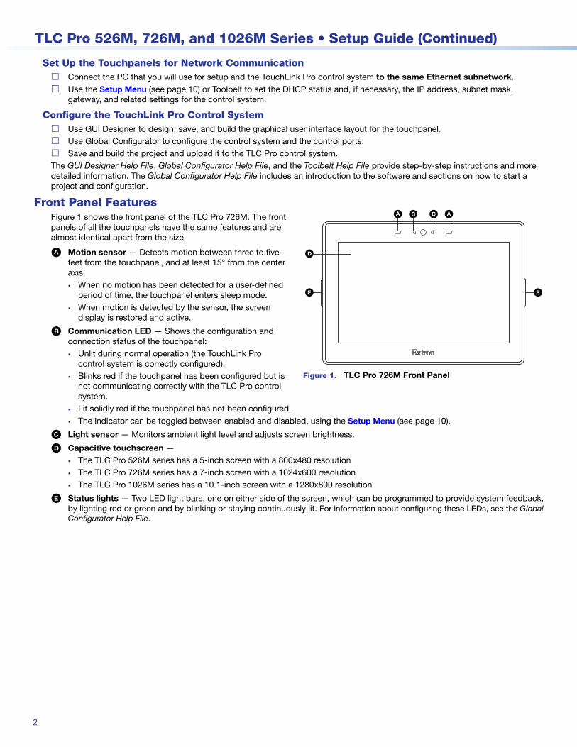
Front Panel FeaturesFigure 1 shows the front panel of the TLC Pro 726M. The front panels of all the touchpanels have the same features and are almost identical apart from the size.
A Motion sensor — Detects motion between three to five feet from the touchpanel, and at least 15° from the center axis.• When no motion has been detected for a user-defined
period of time, the touchpanel enters sleep mode.• When motion is detected by the sensor, the screen
display is restored and active.
B Communication LED — Shows the configuration and connection status of the touchpanel:• Unlit during normal operation (the TouchLink Pro
control system is correctly configured).• Blinks red if the touchpanel has been configured but is
not communicating correctly with the TLC Pro control system.
• Lit solidly red if the touchpanel has not been configured.• The indicator can be toggled between enabled and disabled, using the Setup Menu (see page 10).
C Light sensor — Monitors ambient light level and adjusts screen brightness.
D Capacitive touchscreen — • The TLC Pro 526M series has a 5-inch screen with a 800x480 resolution• The TLC Pro 726M series has a 7-inch screen with a 1024x600 resolution• The TLC Pro 1026M series has a 10.1-inch screen with a 1280x800 resolution
E Status lights — Two LED light bars, one on either side of the screen, which can be programmed to provide system feedback, by lighting red or green and by blinking or staying continuously lit. For information about configuring these LEDs, see the Global Configurator Help File.
AA BB CC AA
DD
EE EE
Figure 1. TLC Pro 726M Front Panel
3
Product Category
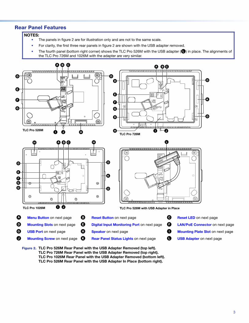
Rear Panel FeaturesNOTES:
• The panels in figure 2 are for illustration only and are not to the same scale.
• For clarity, the first three rear panels in figure 2 are shown with the USB adapter removed.
• The fourth panel (bottom right corner) shows the TLC Pro 526M with the USB adapter (L) in place. The alignments of the TLC Pro 726M and 1026M with the adapter are very similar.
DD
CCAABB
EE
JJ HHTLC Pro 526M
II
GG
DD
FF
CCAA BB
EE
FF
GG
HH II JJ
KK
DD
DD
DD
DD
TLC Pro 726M
CCAABB HHHH
EE
FFGG
DD
DD
KK
DD
DD
II JJTLC Pro 1026M
LL
e
TLC Pro 526M with USB Adapter in Place
A Menu Button on next page B Reset Button on next page C Reset LED on next page
D Mounting Slots on next page E Digital Input Monitoring Port on next page F LAN/PoE Connector on next page
G USB Port on next page H Speaker on next page I Mounting Plate Slot on next page
J Mounting Screw on next page K Rear Panel Status Lights on next page L USB Adapter on next page
Figure 2. TLC Pro 526M Rear Panel with the USB Adapter Removed (top left). TLC Pro 726M Rear Panel with the USB Adapter Removed (top right). TLC Pro 1026M Rear Panel with the USB Adapter Removed (bottom left). TLC Pro 526M Rear Panel with the USB Adapter In Place (bottom right).
figure 2
4
TLC Pro 526M, 726M, and 1026M Series • Setup Guide (Continued)
A Menu Button (see figure 2 on the previous page)— Activates the setup menu (see Setup Menu on page 10).
B Reset Button — Pressing the Reset button allows the unit to be reset in any of four different modes and can also be used to toggle between enabling and disabling the DHCP client (for an overview, see Reset Modes: a Brief Summary on page 9).
C Reset LED — Provides feedback about the reset status when the user presses the Reset button (see Reset Modes: a Brief Summary).
D Mounting Slots — The TLC Pro 726M and 1026M have four, one in each corner. The TLC Pro 526M has two, one in each top corner. The hooks on the corners of the mounting plate (see figure 13, 3, on page 7) fit into these slots for wall mounting.
E Digital Input Monitoring Port — This two-pole captive screw port (1 = signal and G = ground) monitors digital input with or without a +5 VDC pull-up.
F LAN/PoE Connector — Connect the touchpanel to a PoE power injector (not provided) using a twisted pair cable, terminated with an RJ-45 connector. Connect the power injector to the LAN through a nework switch.
ATTENTION:• The TLC Pro 526M, TLC Pro 726M and TLC Pro 1026M are Power over Ethernet (PoE 802.3af, class 3) compliant.
Do not power on the touchpanels until you have read the Attention in the “Rear Panel Features” section of the TLC Pro 526, 726, and 1026 Series User Guide.
• Le TLC Pro 526M, le TLC Pro 726M et le TLC Pro 1026M supportent l’alimentation via Ethernet (PoE 802.3af, classe 3). Veuillez lire la partie « Attention » dans la section « Rear Panel Features » du TLC Pro 526, 726, and 1026 Series User Guide, avant de mettre sous tension les écrans tactiles.
Menu Button
Reset Button
Reset LED
Mounting Slots
Digital Input Monitoring Port
LAN/PoE Connector
NOTE: These touchpanels are shipped without a power injector. The power injector must be purchased separately.
Extron recommends the Extron XTP PI 100 power injector (see figure 3). Your power injector may look different.
figure 2 100-240V ~ 50-60Hz0.4A MAX
XTP
PWR
XTP PWR
To network switch To touchpanel
Figure 3. XTP PI 100 Power Injector
G USB Port — Compatible with USB 2.0.
H Speaker — Provides audible feedback for the user.• TLC Pro 526M — a single speaker• TLC Pro 726M — a single speaker• TLC Pro 1026M — two (dual mono) speakers
I Mounting Plate Slot — The tongue at the bottom of the plate (see figure 13, 4) fits into this slot, for wall mounting.
J Mounting Screw — Tightens against the tongue of the mounting plate to secure the touchpanel.
K Rear Panel Status Lights• TLC Pro 526M — no lights• TLC Pro 726M — Six lights, three on each side of the panel• TLC Pro 1026M — Two lights, one on each side of the panelThese lights can provide system feedback by being configured to light red or green and to blink or stay continuously lit. For information about configuring these LEDs, see the Global Configurator Help File.The rear panel status lights can be toggled between enabled and disabled by using the Setup Menu.
L USB Adapter — Provides additional control ports (see below).
USB Port
Speaker
Mounting Plate Slot
Mounting Screw
Rear Panel Status Lights
USB Adapter
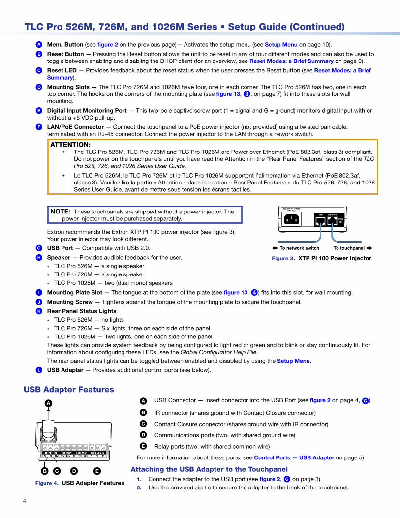
USB Adapter Features
S G IN 1 2 CTx Rx RxG TxIR/C IN COM1 RELAYSCOM2
AA
BB CC DD EEFigure 4. USB Adapter Features
A USB Connector — Insert connector into the USB Port (see figure 2 on page 4, G)
B IR connector (shares ground with Contact Closure connector)
C Contact Closure connector (shares ground wire with IR connector)
D Communications ports (two, with shared ground wire)
E Relay ports (two, with shared common wire)
For more information about these ports, see Control Ports — USB Adapter on page 5)
Attaching the USB Adapter to the Touchpanel1. Connect the adapter to the USB port (see figure 2, G on page 3).2. Use the provided zip tie to secure the adapter to the back of the touchpanel.
5
Product Category
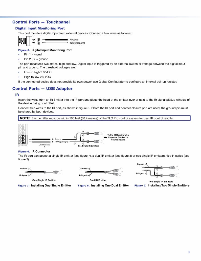
Control Ports — TouchpanelDigital Input Monitoring Port
This port monitors digital input from external devices. Connect a two wires as follows:1G
INPUT Ground
Control Signal
Figure 5. Digital Input Monitoring Port• Pin 1 = signal
• Pin 2 (G) = ground.
The port measures two states: high and low. Digital input is triggered by an external switch or voltage between the digital input pin and ground. The threshold voltages are:
• Low to high 2.8 VDC
• High to low 2.0 VDC
If the connected device does not provide its own power, use Global Configurator to configure an internal pull-up resistor.
Control Ports — USB AdapterIR
Insert the wires from an IR Emitter into the IR port and place the head of the emitter over or next to the IR signal pickup window of the device being controlled.
Connect two wires to the IR port, as shown in figure 6. If both the IR port and contact closure port are used, the ground pin must be shared by both devices.
NOTE: Each emitter must be within 100 feet (30.4 meters) of the TLC Pro control system for best IR control results.
SG
INIR
/C I
N
To the IR Receiver of a Projector, Display, or
Source DeviceS
G(-)
(+)
(-)
(+)
(+)
(-)
Two Single IR Emitters
Ground
IR Output Signal
UnidirectionalIR
Figure 6. IR ConnectorThe IR port can accept a single IR emitter (see figure 7), a dual IR emitter (see figure 8) or two single IR emitters, tied in series (see figure 9).
Ground (−)
IR Signal (+)
One Single IR Emitter
Figure 7. Installing One Single Emitter
Ground (−)
IR Signal (+)
Dual IR Emitter
Figure 8. Installing One Dual Emitter
(+)
(−)
(−)
(+)
IR Signal (+)
Ground (−)
Two Single IR Emitters
Figure 9. Installing Two Single Emitters
6
TLC Pro 526M, 726M, and 1026M Series • Setup Guide (Continued)
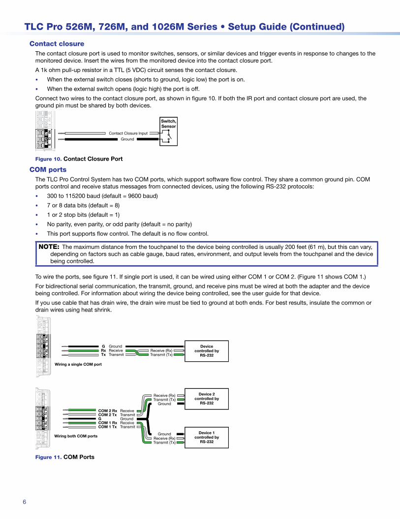
Contact closureThe contact closure port is used to monitor switches, sensors, or similar devices and trigger events in response to changes to the monitored device. Insert the wires from the monitored device into the contact closure port.
A 1k ohm pull-up resistor in a TTL (5 VDC) circuit senses the contact closure.
• When the external switch closes (shorts to ground, logic low) the port is on.
• When the external switch opens (logic high) the port is off.
Connect two wires to the contact closure port, as shown in figure 10. If both the IR port and contact closure port are used, the ground pin must be shared by both devices.
SG
INIR
/C IN
Ground
Contact Closure Input
Switch,Sensor
Figure 10. Contact Closure Port
COM portsThe TLC Pro Control System has two COM ports, which support software flow control. They share a common ground pin. COM ports control and receive status messages from connected devices, using the following RS-232 protocols:
• 300 to 115200 baud (default = 9600 baud)
• 7 or 8 data bits (default = 8)
• 1 or 2 stop bits (default = 1)
• No parity, even parity, or odd parity (default = no parity)
• This port supports flow control. The default is no flow control.
NOTE: The maximum distance from the touchpanel to the device being controlled is usually 200 feet (61 m), but this can vary, depending on factors such as cable gauge, baud rates, environment, and output levels from the touchpanel and the device being controlled.
To wire the ports, see figure 11. If single port is used, it can be wired using either COM 1 or COM 2. (Figure 11 shows COM 1.)
For bidirectional serial communication, the transmit, ground, and receive pins must be wired at both the adapter and the device being controlled. For information about wiring the device being controlled, see the user guide for that device.
If you use cable that has drain wire, the drain wire must be tied to ground at both ends. For best results, insulate the common or drain wires using heat shrink.
Receive (Rx)Transmit (Tx)
TransmitCOM 1 Rx ReceiveCOM 1 Tx
G Ground
1T
xR
xR
xG
Tx
CO
M1
RE
LAY
SC
OM
21R
ELAY
SIN
Tx
Rx
Rx
GT
xIR
/C IN
CO
M1
CO
M2
INIR
/C I
N
TransmitCOM 2 Rx ReceiveCOM 2 Tx
Ground
Receive (Rx)Transmit (Tx)
Ground
Devicecontrolled by
RS-232Receive (Rx)Transmit (Tx)Transmit
Rx ReceiveTx
G Ground
Device 2controlled by
RS-232
Device 1controlled by
RS-232
Wiring a single COM port
Wiring both COM ports
Figure 11. COM Ports
7
Product Category
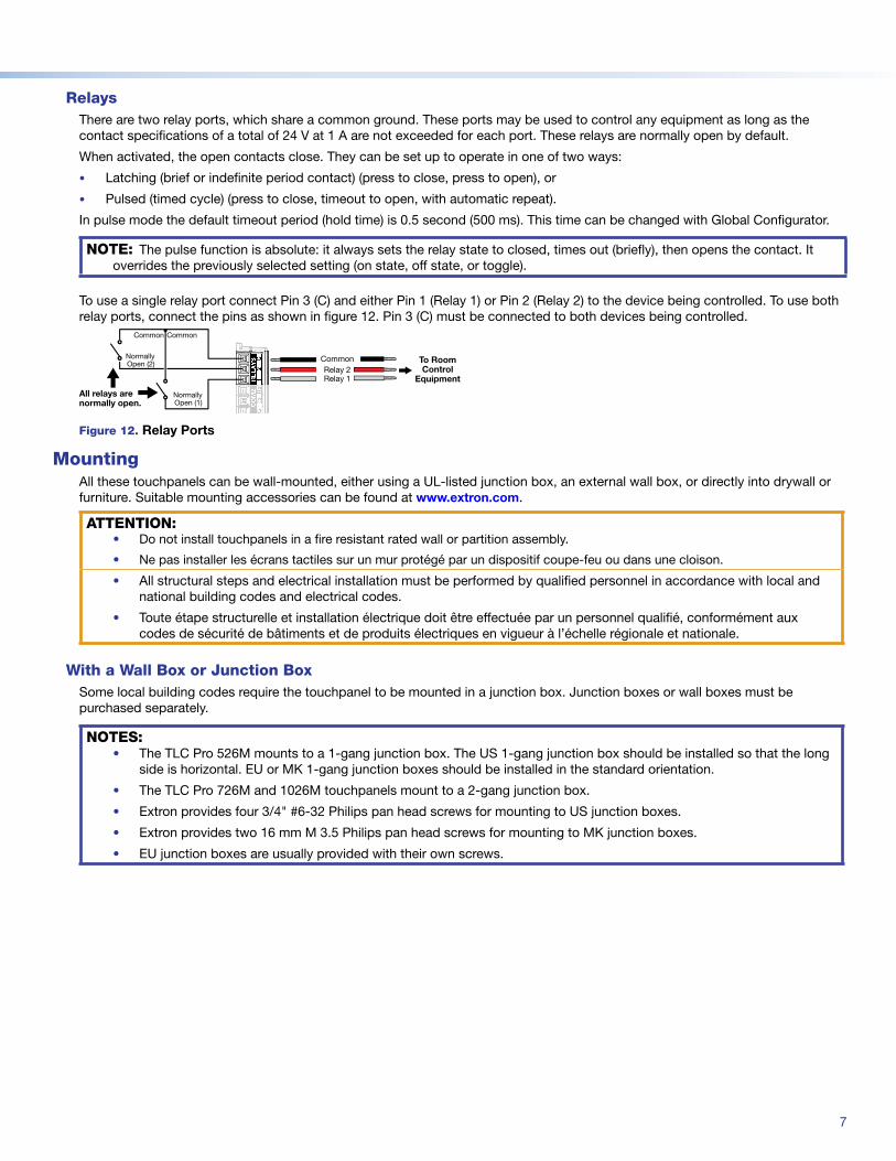
RelaysThere are two relay ports, which share a common ground. These ports may be used to control any equipment as long as the contact specifications of a total of 24 V at 1 A are not exceeded for each port. These relays are normally open by default.
When activated, the open contacts close. They can be set up to operate in one of two ways:
• Latching (brief or indefinite period contact) (press to close, press to open), or
• Pulsed (timed cycle) (press to close, timeout to open, with automatic repeat).
In pulse mode the default timeout period (hold time) is 0.5 second (500 ms). This time can be changed with Global Configurator.
NOTE: The pulse function is absolute: it always sets the relay state to closed, times out (briefly), then opens the contact. It overrides the previously selected setting (on state, off state, or toggle).
To use a single relay port connect Pin 3 (C) and either Pin 1 (Relay 1) or Pin 2 (Relay 2) to the device being controlled. To use both relay ports, connect the pins as shown in figure 12. Pin 3 (C) must be connected to both devices being controlled.
NormallyOpen (2)
Common
NormallyOpen (1)
Common
All relays are normally open.
To Room Control
Equipment
CommonRelay 2Relay 11
2C
RE
LAY
S
Figure 12. Relay Ports
MountingAll these touchpanels can be wall-mounted, either using a UL-listed junction box, an external wall box, or directly into drywall or furniture. Suitable mounting accessories can be found at www.extron.com.
ATTENTION:• Do not install touchpanels in a fire resistant rated wall or partition assembly.
• Ne pas installer les écrans tactiles sur un mur protégé par un dispositif coupe-feu ou dans une cloison.
• All structural steps and electrical installation must be performed by qualified personnel in accordance with local and national building codes and electrical codes.
• Toute étape structurelle et installation électrique doit être effectuée par un personnel qualifié, conformément aux codes de sécurité de bâtiments et de produits électriques en vigueur à l’échelle régionale et nationale.
With a Wall Box or Junction BoxSome local building codes require the touchpanel to be mounted in a junction box. Junction boxes or wall boxes must be purchased separately.
NOTES:• The TLC Pro 526M mounts to a 1-gang junction box. The US 1-gang junction box should be installed so that the long
side is horizontal. EU or MK 1-gang junction boxes should be installed in the standard orientation.
• The TLC Pro 726M and 1026M touchpanels mount to a 2-gang junction box.
• Extron provides four 3/4" #6-32 Philips pan head screws for mounting to US junction boxes.
• Extron provides two 16 mm M 3.5 Philips pan head screws for mounting to MK junction boxes.
• EU junction boxes are usually provided with their own screws.
figure 12
8
TLC Pro 526M, 726M, and 1026M Series • Setup Guide (Continued)
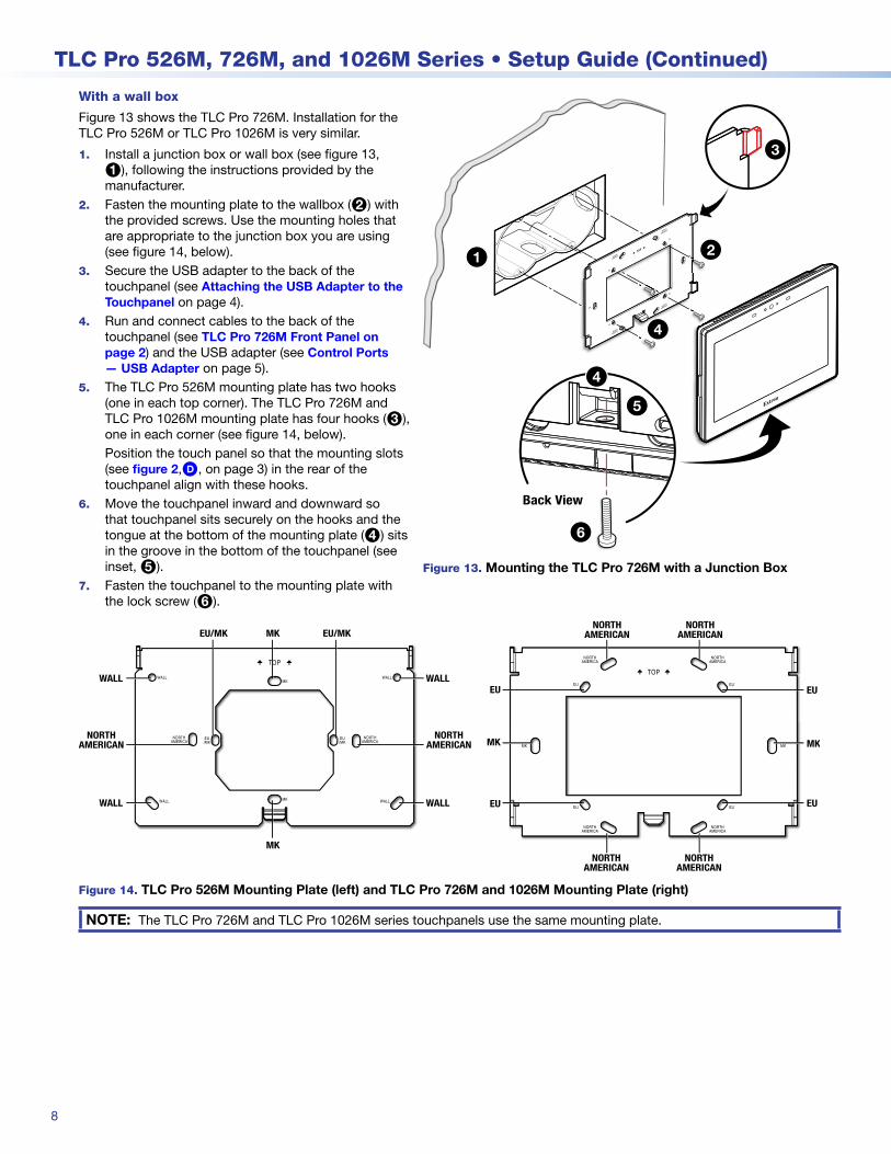
With a wall box
Figure 13 shows the TLC Pro 726M. Installation for the TLC Pro 526M or TLC Pro 1026M is very similar.
1. Install a junction box or wall box (see figure 13, 1), following the instructions provided by the manufacturer.
2. Fasten the mounting plate to the wallbox (2) with the provided screws. Use the mounting holes that are appropriate to the junction box you are using (see figure 14, below).
3. Secure the USB adapter to the back of the touchpanel (see Attaching the USB Adapter to the Touchpanel on page 4).
4. Run and connect cables to the back of the touchpanel (see TLC Pro 726M Front Panel on page 2) and the USB adapter (see Control Ports — USB Adapter on page 5).
5. The TLC Pro 526M mounting plate has two hooks (one in each top corner). The TLC Pro 726M and TLC Pro 1026M mounting plate has four hooks (3), one in each corner (see figure 14, below).Position the touch panel so that the mounting slots (see figure 2,D, on page 3) in the rear of the touchpanel align with these hooks.
6. Move the touchpanel inward and downward so that touchpanel sits securely on the hooks and the tongue at the bottom of the mounting plate (4) sits in the groove in the bottom of the touchpanel (see inset, 5).
7. Fasten the touchpanel to the mounting plate with the lock screw (6).
figure 13
steps 3 through 7
figure 14
TOP
e
Back View
1 2
3
4
5
6
4
Figure 13. Mounting the TLC Pro 726M with a Junction Box
NORTHAMERICAN
NORTHAMERICAN
MK
MK
EU/MK EU/MK
WALL
WALL
WALL
WALL
NORTHAMERICAN
NORTHAMERICAN
NORTHAMERICAN
NORTHAMERICAN
EU
MK
EU
EU EU
MK
Figure 14. TLC Pro 526M Mounting Plate (left) and TLC Pro 726M and 1026M Mounting Plate (right)
NOTE: The TLC Pro 726M and TLC Pro 1026M series touchpanels use the same mounting plate.
9
Product Category
Without a wall box
If the wall box is not required by local building codes, you can mount the touchpanel directly into drywall.
1. Use the mounting plate as a template to mark the wall or download the cut-out template for your product from www.extron.com. Place the template or mounting plate against the wall or furniture in a suitable location and ensure that it is level.
2. Mark the position of the hole and cut the wall.• For the TLC Pro 526M, this hole is 2.4 inches (61 mm) wide x 2.1 inches (53 mm) high.• For the TLC Pro 726M or 1026M, this hole is 3.5 inches (89 mm) wide x 2.0 inches (51 mm) high.
3. Mark the slots labeled WALL (TLC Pro 526M) or MK (TLC Pro 726M or 1026M) (figure 13) and drill the two pilot holes. Extron recommends using two Molly bolts or SnapToggle bolts.
4. Secure the mounting plate to the wall (see figure 13, 2, on the previous page).5. Complete the installation as described in steps 3 through 7 on the previous page.
NOTE: Allow adequate space to accommodate the USB adapter:• For the TLC Pro 526M series, allow a minimum of 1.00" (26 mm) behind the mounting plate.
• For the TLC Pro 726M series, allow a minimum of 1.37" (35 mm) behind the mounting plate.
• For the TLC Pro 1026M series, allow a minimum of 1.40" (36 mm) behind the mounting plate.
Reset Modes: a Brief SummaryThe TLC Pro Control System Series offers the following reset modes:
• Use factory firmware: Press and hold the Reset button (figure 2, B, on page 3) while applying power to the unit. Use this mode to replace firmware in the event of firmware failure.Do not continue to operate the TouchLink Pro control system using the factory firmware version. If you want to use the factory default firmware version, you must upload that version again.
• Project Recovery: This mode is activated using Global Configurator Plus and Professional. See the Global Configurator Help File for more information.
• Run/Stop Program: Hold down the Reset button for about 3 seconds, until the Power LED blinks once. Release and press the Reset button momentarily (for <1 second) within 1 second. (Nothing happens if the momentary press does not occur within 1 second.) The LED blinks 2 times if the program is starting. The LED blinks 3 times if the program is stopping. This mode allows you to restart any programs stopped by an IP settings reset.
• Toggle DHCP Client: This mode toggles between DHCP enabled and DHCP disabled. Press the Reset button five times, consecutively. After the fifth press, do not press the button again within 3 seconds. If DHCP was enabled, it is now disabled and the Reset LED (figure 2, C) blinks three times. If DHCP was disabled, it is now enabled and the Reset LED blinks six times.
NOTES:• DHCP toggle mode is supported on firmware version 3.0 or higher.
• By default DHCP is off and the unit uses a static IP address.
• When you disable the DHCP client, the unit reverts to using the previously-set static IP address.
• Reset All IP Settings: Press and hold the Reset button for 6 seconds. After the Reset LED flashes twice, release and momentarily press the Reset button. Use this mode to reset all network settings without affecting user-loaded files.
• Reset to Factory Defaults: Press and hold the Reset button for 9 seconds. After the Reset LED flashes three times, release and momentarily press the Reset button. Use this mode to return the interface to factory default settings.
NOTE: The factory configured passwords for all accounts on this device have been set to the device serial number. If the device is reset to factory defaults, the password reverts to extron. Passwords are case sensitive.
10
For information on safety guidelines, regulatory compliances, EMI/EMF compatibility, accessibility, and related topics, see the Extron Safety and Regulatory Compliance Guide on the Extron website.
© 2019 Extron Electronics — All rights reserved. www.extron.comAll trademarks mentioned are the property of their respective owners.
Worldwide Headquarters: Extron USA West, 1025 E. Ball Road, Anaheim, CA 92805, 800.633.987668-3385-50 Rev. A
08 19
TLC Pro 526M, 726M, and 1026M Series • Setup Guide (Continued)
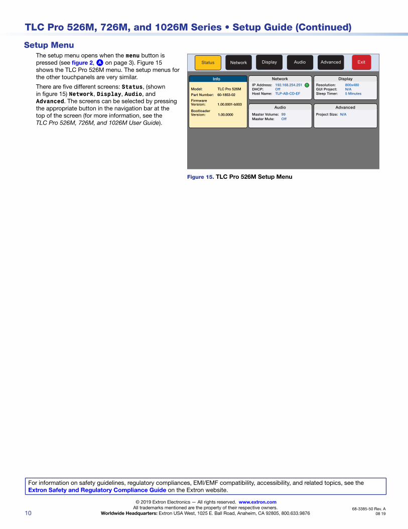
Setup MenuThe setup menu opens when the menu button is pressed (see figure 2, A on page 3). Figure 15 shows the TLC Pro 526M menu. The setup menus for the other touchpanels are very similar.
There are five different screens: Status, (shown in figure 15) Network, Display, Audio, and Advanced. The screens can be selected by pressing the appropriate button in the navigation bar at the top of the screen (for more information, see the TLC Pro 526M, 726M, and 1026M User Guide).
Status Display Audio Advanced ExitNetwork
Info
Model: TLC Pro 526M
Part Number: 60-1853-02
FirmwareVersion: 1.00.0001-b003
Network
IP Address:DHCP:Host Name:
Off192.168.254.251
TLP-AB-CD-EF
Display
Resolution:GUI Project:Sleep Timer:
800x480N/A5 Minutes
Audio
Master Volume:Master Mute: Off
99
Advanced
N/AProject Size:BootloaderVersion: 1.00.0000
Figure 15. TLC Pro 526M Setup Menu