overview on use of a molten salt htf in a trough solar ... · than in field piping • with vp-1,...
TRANSCRIPT

Overview on use of a Molten Salt HTF in a Trough Solar Field
D. Kearney Kearney & Associates U. Herrmann, P. Nava Flabeg Solar InternationalB. Kelly Nexant, Inc. R. Mahoney, J. Pacheco Sandia Natl Labs LabR. Cable, KJC Operating Co. D. Blake, H. Price NRELN. Potrovitza
NREL Parabolic Trough Thermal Energy Storage WorkshopGolden, CO, February 20-21, 2003
NREL/PR-550-40028

NREL TES Workshop-Golden-Feb03 2
Disclaimer and Government License
This work has been authored by Midwest Research Institute (MRI) under Contract No. DE-AC36-99GO10337 with the U.S. Department of Energy (the “DOE”). The United States Government (the “Government”) retains and the publisher, by accepting the work for publication, acknowledges that the Government retains a non-exclusive, paid-up, irrevocable, worldwide license to publish or reproduce the published form of this work, or allow others to do so, for Government purposes.
Neither MRI, the DOE, the Government, nor any other agency thereof, nor any of their employees, makes any warranty, express or implied, or assumes any liability or responsibility for the accuracy, completeness, or usefulness of any information, apparatus, product, or process disclosed, or represents that its use would not infringe any privately owned rights. Reference herein to any specific commercial product, process, or service by trade name, trademark, manufacturer, or otherwise does not constitute or imply its endorsement, recommendation, or favoring by the Government or any agency thereof. The views and opinions of the authors and/or presenters expressed herein do not necessarily state or reflect those of MRI, the DOE, the Government, or any agency thereof.
NREL TES Workshop-Golden-Feb03 3
Concept & Objectives
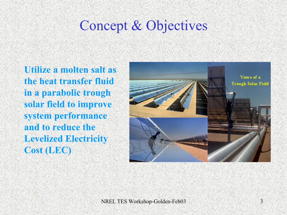
Utilize a molten salt as the heat transfer fluid in a parabolic trough solar field to improvesystem performance and to reduce the Levelized Electricity Cost (LEC)
NREL TES Workshop-Golden-Feb03 4
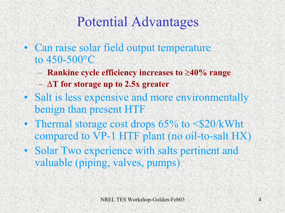
Potential Advantages
• Can raise solar field output temperature to 450-500°C– Rankine cycle efficiency increases to ≥40% range– ΔT for storage up to 2.5x greater
• Salt is less expensive and more environmentally benign than present HTF
• Thermal storage cost drops 65% to <$20/kWht compared to VP-1 HTF plant (no oil-to-salt HX)
• Solar Two experience with salts pertinent and valuable (piping, valves, pumps)

NREL TES Workshop-Golden-Feb03 5
Potential Disadvantages
• High freezing point of candidate salts– Leads to significant O&M challenges– Innovative freeze protection concepts required
• More expensive materials required in HTF system due to higher possible HTF temperatures
• Selective surface durability and salt selection will determine temperature limits
• Solar field heat losses will rise, though emissivity of 0.075 (from 0.1) would regain performance
NREL TES Workshop-Golden-Feb03 6
Some Key Questions
• What is the practical upper temperature limit?• Is the O&M with salt feasible in a trough field, particularly
freeze protection?• Do materials, O&M, performance, etc. push the solar system
capital cost too high, or in fact will the cost be reduced?• Can we lower electricity cost with this approach? And add
important flexibility with thermal storage?

NREL TES Workshop-Golden-Feb03 7
Power block type: Steam Rankine cycle Power block capacity: 50 MW gross Steam turbine inlet conditions:
PressureTemperature
66 bar, 100 bar nominally 400-500C
Steam turbine cycle efficiency: determined by GateCycle calculation, nominally 38.5-41.1% for these conditions. Solar field outlet salt temperature:
Nominal Maximum
450°C ~500°C
Optical: Overall optical efficiency 0.75 Power Block Capacity, MW 55 gross Performance runs: Thermal storage capacity 6h Annual Insolation Barstow Collector type Generic SEGS type with
advanced features
Receiver Current Solel Receiver ε=0.1@ 400C
Operating scenario Solar only
General System Conditions

NREL TES Workshop-Golden-Feb03 8
Characteristics of the Nitrate Salts and Therminol VP-1
PropertySolarSalt
Hitec HitecXL
(Calcium Nitrate
Salt)
LiNO3mixture
TherminolVP-1
Diphenylbiphenyl
oxideComposition, %
NaNO3 60 7 7
KNO3 40 53 45
NaNO2 40
Ca(NO3)2 48
Freezing Point, C 220 142 120 120 13
Upper Temperature, C 600 535 500 550 400
Density @ 300C, kg/m3 1899 1640 1992 815
Viscosity @ 300C, cp 3.26 3.16 6.37 0.2
Heat capacity @ 300C, J/kg-K 1495 1560 1447 2319

NREL TES Workshop-Golden-Feb03 9
Effective Storage Fluid Cost
Salt
Temperature Rise
Cost per Kg
Storage Cost
°C $/kg $/kWh Hitec (a) [142°C] 200 0.93 10.7 Solar Salt (b) [220°C] 200 0.49 5.8 Calcium Nitrate [HitecXL] (c) [120°C]
200 150 100
1.19 1.19 1.19
15.2 20.1 30.0
Therminol VP-1 (d) 100 3.96 57.5
a) 7:53 Na:K Nitrate, 40 Na Nitrite c) 42:15:43 Ca:Na:K Nitrateb) 60:40 Na:K Nitrate d) Diphenyl/biphenyl oxide

NREL TES Workshop-Golden-Feb03 10
Candidate Thermal Storage Systems• 2-Tank Configuration
– Hot and Cold Tanks– Used at Solar Two … good engineering experience– Judged to ready for commercial use
• Single Tank Thermocline– Good option -> costs estimated to be 65% less– Requires further development– 20 MWth prototype operated at SNLA
• Freeze protection in storage systems less complex than in field piping
• With VP-1, an expensive oil-to-salt HX is required. A molten salt HTF eliminates that need.
NREL TES Workshop-Golden-Feb03 11
VS
Cold Salt Tank Hot Salt Tank
VS
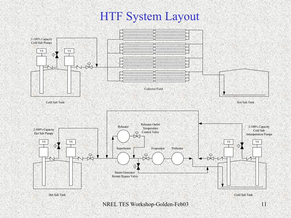
2-100% CapacityCold Salt Pumps
Collector Field
VS
Hot Salt Tank
VS VS
Cold Salt Tank
VS
2-100% CapacityHot Salt Pumps
2-100% CapacityCold Salt
Attemperation Pumps
Superheater
Reheater
Evaporator Preheater
Reheater OutletTemperature
Control Valve
Steam GeneratorRestart Bypass Valve
HTF System Layout

NREL TES Workshop-Golden-Feb03 12
Comparative Levelized Electricity Cost

NREL TES Workshop-Golden-Feb03 13
Engineering on solar field pipinglayout and design of major equipment
was carried out for use in the performance and cost models

NREL TES Workshop-Golden-Feb03 14
Solar Field Layout Solar Field Parameters for 55 MWe Plant
1155 m 125.0 Solar field peak thermal outpuMWt879.0 Total salt HTF mass flowrate kg/s28.4 Header corridor m
100.5 Total length per SCA mQuad 1 Quad 2 12.2 Outer road corridors m
69.6 Allowance E-W for power blockm402 Length of 1 row with 4 SCAs m
Power 857 m 1155 E-W total width mBlock 857 N-S total width m
hot HTF in header and illustrative loopscold HTF in header and illustrative loops
Quad 3 Quad 4
270,320 SF aperture area m2496 Total SCAs
N 62 Total rows62 Total loops
17.4 Solar row spacing5.76 Mirror aperture
4 SCAs/row SALT HTF SOLAR P OWER B LOC K 8 SCAs/loop FIELD LAYOUT N OT T O SC A LE 989,949 Total land area m2
99 Total land area hectares245 Total land area acres

NREL TES Workshop-Golden-Feb03 15
Optical Efficiency BackupOptical Efficiency
ComparisonSandia
LS-2 TestSEGS VI
LS-2 1999New LS-2 Collector
Advanced Trough
Bellows Shadowing 0.974 0.971 0.974 0.974
Tracking Error & Twist 0.994 0.994 0.994 0.994
Geometric Accuracy 0.98 0.98 0.98 0.98
Mirror Reflectivity 0.935 0.935 0.935 0.95
Dust on Mirrors 0.974 0.931 0.95 0.97
Dust on HCE 0.99 0.977 0.983 0.99
Envelope Transmissivity 0.965 0.965 0.97 0.97
Absorption 0.925 0.937 0.96 0.97
Unaccounted 0.96 0.96 0.97 0.98
Optical Efficiency 0.73 0.70 0.75 0.80
NREL TES Workshop-Golden-Feb03 16
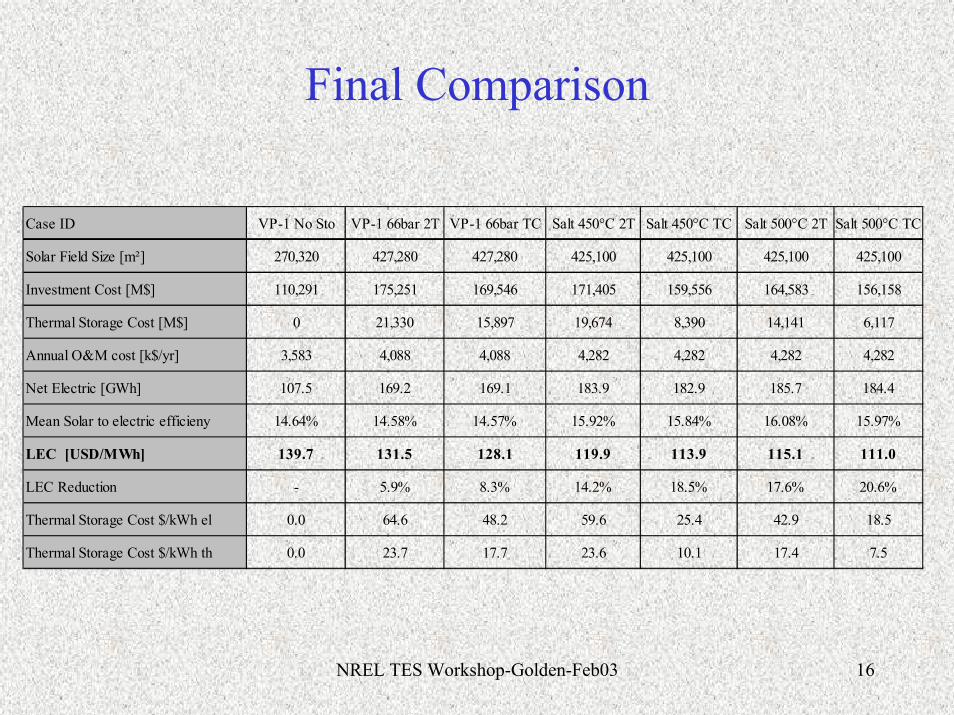
Final Comparison
Case ID VP-1 No Sto VP-1 66bar 2T VP-1 66bar TC Salt 450°C 2T Salt 450°C TC Salt 500°C 2T Salt 500°C TC
Solar Field Size [m²] 270,320 427,280 427,280 425,100 425,100 425,100 425,100
Investment Cost [M$] 110,291 175,251 169,546 171,405 159,556 164,583 156,158
Thermal Storage Cost [M$] 0 21,330 15,897 19,674 8,390 14,141 6,117
Annual O&M cost [k$/yr] 3,583 4,088 4,088 4,282 4,282 4,282 4,282
Net Electric [GWh] 107.5 169.2 169.1 183.9 182.9 185.7 184.4
Mean Solar to electric efficieny 14.64% 14.58% 14.57% 15.92% 15.84% 16.08% 15.97%
LEC [USD/MWh] 139.7 131.5 128.1 119.9 113.9 115.1 111.0
LEC Reduction - 5.9% 8.3% 14.2% 18.5% 17.6% 20.6%
Thermal Storage Cost $/kWh el 0.0 64.6 48.2 59.6 25.4 42.9 18.5
Thermal Storage Cost $/kWh th 0.0 23.7 17.7 23.6 10.1 17.4 7.5
NREL TES Workshop-Golden-Feb03 17
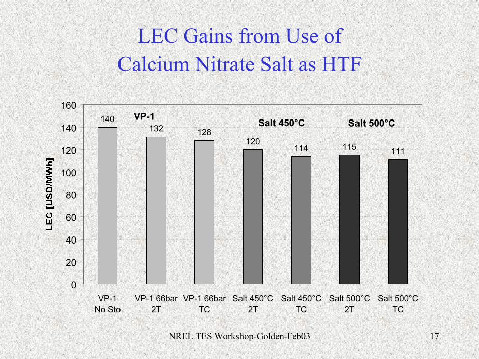
LEC Gains from Use of Calcium Nitrate Salt as HTF
140128
120114 115 111
132
0
20
40
60
80
100
120
140
160
VP-1 No Sto
VP-1 66bar2T
VP-1 66barTC
Salt 450°C2T
Salt 450°CTC
Salt 500°C2T
Salt 500°CTC
VP-1 Salt 450°C Salt 500°C

NREL TES Workshop-Golden-Feb03 18
Concept Overview
• Study concluded that no overriding barriers prevent its adoptionat 450°C. R&D is needed, particularly to reach 500°C operation.
• Feasible solutions have been put forward for system charging, freeze protection, recovery from freezing, and routine maintenance tasks. Selective surface and ball joints present greater challenges.
• There is no compelling economic advantage to using molten salt in a trough solar field for a system without thermal storage
• There appears to be significant economic advantages for a molten salt HTF with storage. Preliminary estimates on reductions in LEC from the reference VP-1 case (w/o storage) are significant.

NREL TES Workshop-Golden-Feb03 19
Engineering Issues

NREL TES Workshop-Golden-Feb03 20
Issues addressed
• Routine Freeze Protection• Solar Field Preheat Methods• Collector Loop Impedance Heating• Materials Considerations

NREL TES Workshop-Golden-Feb03 21
Freeze Protection Methods
• Heat Collection Element– Cold salt circulation in routine overnight operation– Impedance heating for maintenance outage– Resistance heating cable internal to the HCE – Drain loop to service truck for loop piping
maintenance
• HTF Header Piping– Cold salt circulation in routine overnight operation– Electric heat tracing for maintenance outage

NREL TES Workshop-Golden-Feb03 22
Overnight Cooling
0
50
100
150
200
250
300
350
16:00 18:00 20:00 22:00 0:00 2:00 4:00 6:00 8:00
Time
0h TES
1h TES
6h TES
Cooling curves for Solar Fields with Salt HTF
NREL TES Workshop-Golden-Feb03 23
HCE Heating
• Internal resistance heating– Considered possible but cumbersome
• Impedance heating– Circumferentially uniform– Higher power densities possible– Electric system requirements high

NREL TES Workshop-Golden-Feb03 24
Collector Loop Maintenance
• Drain hot HTF into maintenance truck under slight vacuum
• Perform maintenance, e.g., HCE replacement
• Heat loop with impedance heating, and pump salt mixture into loop

NREL TES Workshop-Golden-Feb03 25
Normal Maintenance & Operation
• Within the solar field, O&M practices will change for HTF system and flow loop only, requiring different procedures for:– HCE replacement, requiring taking loops out of service– Maintenance of valves, interconnections, and other fittings– Heat trace systems– Major equipment: Pumps; steam generator; TES– Instrumentation to monitor salt temperatures and heat trace
system operation• Conservative but preliminary cost adders included in
O&M budget
NREL TES Workshop-Golden-Feb03 26
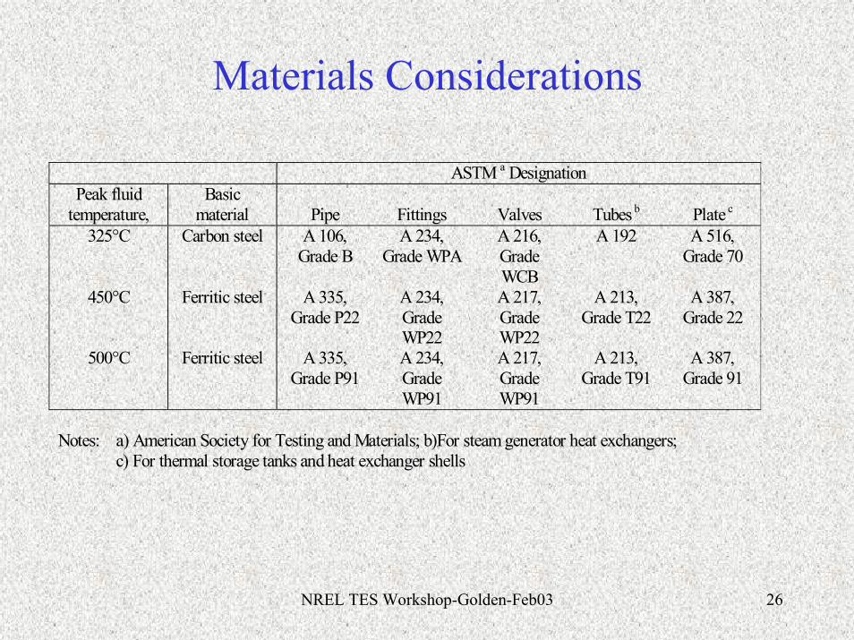
Materials Considerations ASTM a Designation
Peak fluid temperature,
Basic material
Pipe
Fittings
Valves
Tubes b
Plate c
325°C Carbon steel A 106, Grade B
A 234, Grade WPA
A 216, Grade WCB
A 192 A 516, Grade 70
450°C Ferritic steel A 335, Grade P22
A 234, Grade WP22
A 217, Grade WP22
A 213, Grade T22
A 387, Grade 22
500°C Ferritic steel A 335, Grade P91
A 234, Grade WP91
A 217, Grade WP91
A 213, Grade T91
A 387, Grade 91
Notes: a) American Society for Testing and Materials; b)For steam generator heat exchangers; c) For thermal storage tanks and heat exchanger shells
NREL TES Workshop-Golden-Feb03 27
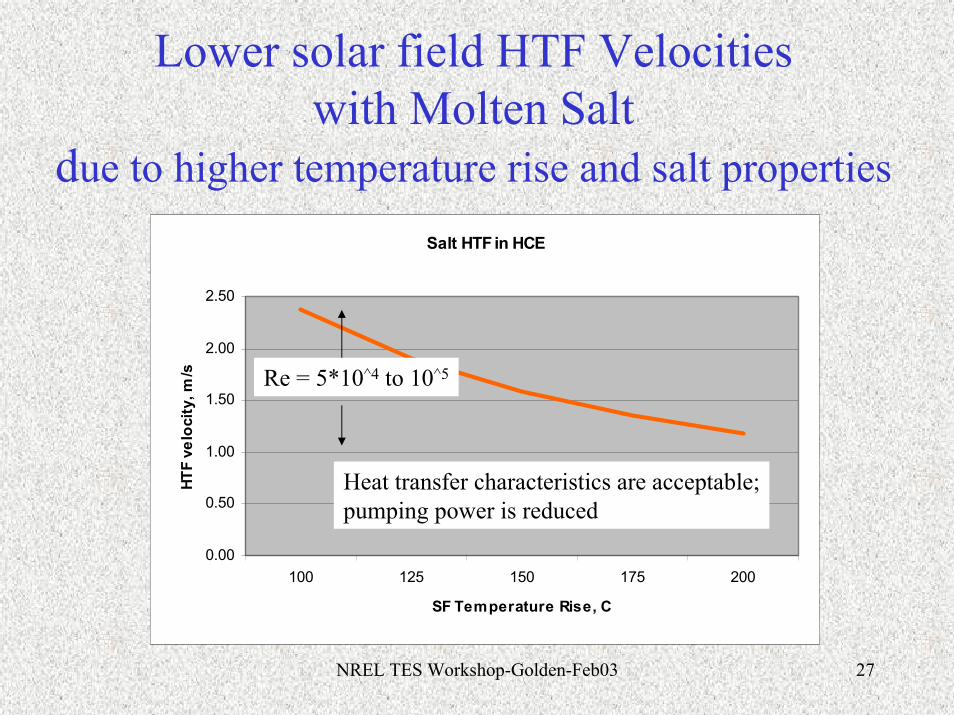
Lower solar field HTF Velocities with Molten Salt
due to higher temperature rise and salt properties
VP-1 velocity 3.45 m/s
Salt HTF in HCE
0.00
0.50
1.00
1.50
2.00
2.50
100 125 150 175 200
SF Temperature Rise, C
HTF
velo
city
, m/s Re = 5*10^4 to 10^5
Heat transfer characteristics are acceptable;pumping power is reduced