overview of umts - educypediaeducypedia.karadimov.info/library/umts_tech-paper.pdf · anywhere and...
TRANSCRIPT

Overview of UMTS
Guoyou He (51005L) Telecommunication Software and Multimedia Laboratory
Helsinki University of Technology [email protected]

1
Contents
ABSTRACT ...................................................................................................................................................................... 2
1 INTRODUCTION .................................................................................................................................................... 3
2 EVOLUTION FROM GSM TO UMTS.................................................................................................................. 4
3 UMTS ARCHITECTURE ..................................................................................................................................... 12 3.1 UTRAN............................................................................................................................................................. 12 3.2 UMTS CORE NETWORKS .................................................................................................................................. 13 3.3 UMTS TERMINALS............................................................................................................................................ 20
4 UMTS PROTOCOLS............................................................................................................................................. 22 4.1 UU INTERFACE PROTOCOL................................................................................................................................. 23 4.2 PROTOCOL ARCHITECTURE OF MAIN INTERFACES ACROSS UMTS ................................................................... 24
5 UMTS SERVICES.................................................................................................................................................. 26 5.1 UMTS QOS ARCHITECTURE ............................................................................................................................. 26 5.2 SERVICE CAPABILITIES AND END USER SERVICES ENABLED BY UMTS............................................................ 29
6 UMTS MARKET.................................................................................................................................................... 33 6.1 3G MARKET SHARES......................................................................................................................................... 33 6.2 VENDORS PRODUCTS AND STRATEGIES............................................................................................................. 35 6.3 TERMINAL AVAILABILITY ................................................................................................................................. 37
7 CONCLUSION ....................................................................................................................................................... 39
ABBREVIATION........................................................................................................................................................... 39
REFERENCES ............................................................................................................................................................... 43

2
Abstract Since the analog cellular systems involved in our life, mobile communications have evolved to its third generation (3G)). The richness of features and functionalities with high quality of service in 3G will bring people to a fascinating world. UMTS is the European vision of 3G mobile communication systems. One of the key functionalities of UMTS is the ability to provide services anywhere and anytime. In UMTS the mobile equipment will be used for any possible purpose such as communication, entertainment, business and all kinds of services. This essay reviews the UMTS systems as a 3G platform for mobile communications and services. It gives an overview of UMTS systems from the areas including its evolution, architecture, protocols and service capabilities. It also analyses the UMTS markets and presents UMTS vendors’ products and strategies as well as their recent activities in 3G. The content of this essay is mainly divided into five key parts: the first part is Evolution of UMTS which gives an overall picture for the history of UMTS development and the evolution process of mobile communication systems from GSM to UMTS; the second part is UMTS architecture, which illustrates the technical and service architectures of the three key subsystems, UTRAN, CN network and Terminals, in the UMTS systems; the third part is UMTS protocols, which presents the main protocols used from UE to service provider across UTRAN and PS CN in the UMTS systems; the fourth part is service capabilities, which summarizes the possible services supported by the UMTS networks and the enabled services for the end users; the fifth part is UMTS market, which firstly shows the UMTS systems market shares in the near past years and the prediction on potential big markets for UMTS deployment in near future based on the public information; then it is presented that the UMTS vendors’ products, strategies and their recent activities in 3G. The available 3G terminals are listed as the final part in this section. The specification on 3G is an evolving process. Many features and functionalities of UMTS are still under development. Vendors battle on pushing their UMTS networks and technologies. Though the process of development and deployment UMTS will be tough, UMTS shall finally change the way of our life and bring people to a brilliant new world.

3
1 Introduction Since the introduction of commercial cellular systems in the late 1970s and early 1980s, mobile communication is evolving to its third generation, 3G. The first generation, 1G, mobile communication systems transmit only analog voice information and provide basic mobility. The most prominent 1G systems are AMPS, NMT, and TACS. They were incompatible due to the scope of national specifications. The development of the second generation, 2G, mobile communication systems was driven by the growth need for systems compatibility, capacity, coverage and improved transmission quality. The development of 2G mobile communication systems started in early 1980s. 2G emphasized on the mobile networks compatibility. Speech transmission was still the main supported services, but data transmissions and supplementary service such as fraud prevention and encrypting of user data became standard features of 2G systems. The main 2G systems include:
• GSM was firstly opened in Finland in 1991. • D-AMPS started its commercial operation in US in 1994. • PDC was put into commercial use by NTT in Japan in 1994. • CDMA started its commercial operation in Hong Kong and Korea in 1995.
Today, multiple 1G and 2G standards are used in worldwide mobile systems, and most of them are incompatible. The most successful implementation of 2G is GSM. Due to the regional nature of 2G mobile communication systems specifications, GSM did not succeed completely in implementing globalization. Based on GSM, the third generation, 3G, aims to implement the globalization of mobile communications. The research for 3G started in 1991. The primary requirements for 3G as described in [10] are:
• The system must be fully specified and world-widely valid, the major interfaces of the system should be standardized and open.
• The system must have clearly added value to GSM in all aspects and be backward compatible at least with GSM and ISDN at the beginning.
• The system must support multimedia and all of its components. • The radio access of 3G must provide wideband capacity be generic enough to be world-
widely available. • The services must be independent from radio access technology and the network
infrastructure must not limit the services to be generated. With the evolution of communications technologies, the traditional telecommunications and the Internet are merging rapidly. The combination of these two worlds and the trends of telecommunications moving to “All IP” require 3G to fulfill more requirements except above primary ones to fit the changes.

4
UMTS[10] is the European vision of 3G mobile communication systems. It represents an evolution in terms of services and data speeds from today's 2G mobile networks. UMTS represents the move into 3G of mobile networks. It addresses the growing demand of mobile and Internet applications for new capacity in today’s overcrowded mobile communications. UMTS increases transmission speed up to 2 Mbps per mobile user and establishes a global roaming standard. It allows many more applications to be introduced to a worldwide base of users and provides a vital link between current multiple GSM systems and the ultimate single worldwide standard systems for all mobile telecommunications. The specifications of UMTS are under development in 3GPP[1]. To reach global acceptance, 3GPP is introducing UMTS in phases:
• 3GPP R99 Most of the specifications were frozen in March of 2000. It laid the foundations for high-speed traffic transfer in both circuit switched and packet switched modes by defining enhancements and transitions for existing GSM networks and specifying the development of new radio access network.
• 3GPP R4 Most of the core technical specifications were frozen in March 2001. It is a minor release with the evolutions including UTRAN access with QoS enhancement, CS domain evolution with introducing MSC server and MGWs based on IP protocols, enhancements in LCS, MMS, MExE, etc.
• 3GPP R5 Most of the specifications and technical reports were frozen in March 2002 or June 2002. It is a major release aiming to utilize IP networking as much as possible. IP and overlying protocols will be used in both networks control and user data flows, i.e. implement “All IP” network, but the IP-based network should still support circuit switched networks. The features of this release mainly include the introduction of IMS[6], enhancement in WCDMA[8], MMS, and LCS. In 3GPP R99 the basis for the UMTS radio access is WCDMA. In 3GPP R4/R5 GSM/EDGE Radio Access Network (GERAN) is specified as an alternative for radio access to build a UMTS mobile network.
• 3GPP R6 It is still being defined with the target June 2003. In this release, a lot of enhancements and improvements in IMS, MBMS, MMS, QoS, GERAN will be specified. Many new services such as digital rights management, speech recognition and speech enabled services and priority service will be specified.
UMTS is already a reality. Japan launched the world's first commercial WCDMA network in 2001. Nokia and AT&T Wireless complete first live 3G EDGE call on November 1, 2001. Telenor launched the first commercial UMTS network in Norway in December 1, 2001. On February 20, 2002, Nokia and Omnital Vodafone made the first rich call in an end-to-end All IP mobile network. In 2002, many of the main UMTS vendors announced their progresses in the battle of pushing their 3G networks and technologies[11, 12].
2 Evolution from GSM to UMTS Moving from GSM to UMTS includes evolutions in three aspects, technical, network architecture and services. Technical evolution depicts the development path of how network elements will be implemented and with what kind of technology. With technical evolution, network will evolve correspondingly due to network elements together form a network. Service evolution is based on the real or imagined demands generated by the end users.

5
In the technical and network aspects, the main idea behind GSM specifications was to define open interfaces, which determine the standardized GSM system components. The openness of the interfaces allows network components from different suppliers to be fit in same network seamlessly. The definition of open interfaces divides a GSM system into different subsystems, and each of them completes specific functionalities. Compared to the analog mobile networks, this division increases the overall system performance by decentralized intelligence. GSM system specifications expected to define three open interfaces, and correspondingly the system was divided into four subsystems, MS, BSS, NSS and NMS as shown in Figure 2-1. In reality, two interfaces, Um interface and A interface, were open, the third one between NMS and NSS/BSS was manufacturer specific due to the delay of its specifications.
NMS
BSS
Um A
BTS TRAU BSC GMSC MSC/VLR
HLR/AuC/EIR
NSS MS
PSTN
X.25
PSPDN
ISDN
V A S
I N
HW&SW Changes for HSCSD GSM Phase 2+
C A M E L
Figure 2-1: GSM network[10] MS is composed of ME and SIM, and subscriber’s data is stored in SIM. BSS is responsible for radio path control and it is composed of BSC, BTS and TRAU. BSC is the central part of BSS and it controls the radio network. BTS maintains the Um interface. It takes care of air interface signaling, ciphering, and speech processing. TRAU handles speech transcoding. NSS takes care of call control functions and it has the elements, MSC, VLR, GMSC, HLR, AuC and EIR. MSC is responsible for call control, BSS control functions, interworking functions, charging, statistics and interface signaling towards BSS and interfacing with external networks. VLR is mainly responsible for subscriber data and service handling and mobility management. GMSC participates in mobility management, communication management and connections to external networks. The main functions of HLR are subscriber data and service handling, statistics and mobility management. Both AuC and EIR take care of security issues together with VLR. AuC maintains subscriber identity related security information, and EIR maintains mobile equipment identity related security information. NMS is the operation and maintenance related part of the network. Quality and services of the network can be observed and maintained through NMS.
6
The actual network needed for call establishing is composed of NSS, BSS and MS. Every call is connected through BSS and NSS. In the service aspect, data transfer capability is the most remarkable difference between 2G and 1G; basic GSM offers 9.6 kb/s symmetric data connection between the network and the terminal. Adding service nodes and service centers, VAS platforms, on top of the existing infrastructure is the natural step for developing basic GSM to provide services. The VAS platform equipment uses standard interfaces towards the GSM network and may or may not have interfaces towards other networks. The minimum VAS platform contains typically SMSC and VMS. Basic GSM and VAS are basically intended to provide services for mass people. With service evolution, more individual services are required from the end users. At this point IN was introduced and integrated together with the GSM network to make individual services possible. IN platform is a complex entity, to integrate IN functionality in GSM system, major changes are required in switching network elements. IN takes big step towards individual services such as Pre-Paid, Free Phone/Toll-free, Premium Rate, Calling Card, Single Number Service, etc. The first phase of GSM specifications provides 9.6 kb/s circuit switched symmetric transmission capability for the supported data services. This capability could not fulfill the increased requirements for mobile data transfer due to the growth of using Internet and electronic messaging. To ease this situation, HSCSD[9] was the first GSM Phase 2+ work item that increased the available data rate in the GSM system with bit rate of 14.4 kb/s channel coding, and up to 8 traffic channels can be used instead of one. The theoretical maximum air interface bit rate of HSCSD is up to 115.2 kb/s. HSCSD can be used in conjunction with both 9.6 kb/s and 14.4 kb/s bearers, enabling a maximum data transfer speed of up to 40-50 kb/s in reality. The biggest disadvantage of HSCSD is that it is very expensive for the user. More channels mean that subscribers have to pay more. More introductions of data services into GSM systems, it became more evident that the circuit switched bearer services were not the best possible media for data traffic with bursty nature. To make GSM systems more suitable for efficient data transfer, GPRS[9] was introduced as shown in Figure 2-2. GPRS brings the packet switched bearer services to the existing GSM systems. It requires some hardware and software changes in MS and BSS and also introduces a few new network elements, SGSN, GGSN, PTM-SC, BG, Inter-PLMN and Intra-PLMN backbone networks as shown in Figure 2-3, among them SGSN and GGSN are the most important two elements. SGSN is the service access point to GPRS network and handles mobility management, authentication, MS registration and protocol conversion. GGSN is connected to external networks like Internet and X.25. It is a router to a sub-network and hides the GPRS infrastructure from the external networks. GPRS introduces packet switching to the GSM network all the way from a server in an external IP network to a mobile station. It integrates with existing GSM systems and reuses the GSM radio network infrastructure and the same transmission links between the GSM network nodes. Theoretical maximum speed of up to 171.2 kb/s is achievable with GPRS using all eight timeslots at the same time. It is possible that GPRS uses asymmetric connections when required and utilizes network resources more efficiently. GPRS starts the development path of converting more and more traditional circuit switched services to packet switched services and brings IP mobility and Internet closer to GSM subscribers though it is not a complete IP mobility solution. When services use

7
packet switched connections, the QoS is a critical issue. Though GPRS can achieve the theoretical maximum data transmission speed of 171.2 kb/s, it requires a single user takes over all eight
Gb
NMS
BSS
Um A
BTS TRAU BSC
HLR/AuC/EIR
GMSC MSC/VLR
NSSMS
PSTN
X.25
PSPDN
ISDN
V A S
I N
HW&SW Changes for GPRS
GGSN SGSN
GPRS Packet Core
Other Data Netwrok
Interent
C A M E L
Figure 2-2: Introduction of GPRS[10]
Local area network
Server
Router
Local area network
Server
Router
Corporate 2
Corporate 1
Intra-PLMN backbone network (IP based)
Serving GPRS Support Node (SGSN)
Point-To- Multipoint Service Center (PTM SC)
Gateway GPRS Support Node (GGSN)
GPRS INFRASTRUCTURE
HLR/AuC MSC
BSC BTS Packet network PSTN
Packet network SS7 Network
Packet network
Data network (Internet)
Packet network
Data network (X.25)
Packet network Inter-PLMN
Backbone network
Border Gateway (BG)
Gb Gr Gd
Gi.IP
Gi.X.25
Firewall
Firewall
Firewall
Um R/S
SMS-GMSC Gr Gd
Gs
Gs
Gp
Gn
Gn
EIR MAP-F
Figure 2-3: Functional view of GPRS[9]

8
timeslots without any error protection. In practice, GPRS speeds need to be checked against the reality of constraints in the networks and terminals. The reality is that the bandwidth available to a GPRS user will be limited to one to four timeslots due to hardware limitations. In addition, though GPRS supports QoS but in reality GPRS traffic has secondary priority in GSM networks traffic, QoS cannot be guaranteed due to GPRS traffic uses unused network resources that cannot be known exactly in advance. To solve above problems, EDGE[9] was introduced. EDGE is specified using 8-PSK [9] that will enhance the throughput per timeslot for both GPRS and HSCSD as shown in Figure 2-4. The development of EDGE is divided into phase 1 and phase 2, which are also known as E-GPRS[9] and E-HSCSD[9] respectively. In phase 1, BSS is renamed as E-RAN[10], and channel coding and modulation methods are defined to enable data rates for packet switched traffic up to 384 kb/s. In phase 2, the same speed is defined to achieve for circuit switched traffic.
Gb
NMS
E-RAN
Um A
BTS TRAU BSC
HLR/AuC/EIR
GMSC MSC/VLR
NSSMS
PSTN
X.25
PSPDN
ISDN
V A S
I N
HW&SW Changes for EDGE
GGSN SGSN
E-GPRS Packet Core
Other Data Netwrok
Interent
C A M E L
Figure 2-4: Introduction EDGE to GPRS system[10] In the path of moving to 3G, GPRS is the first step. If GPRS is already in use, EDGE is the most effective as the second step that gives a low impact on migration. Only software upgrades and EDGE plug-in transceiver units are needed. The existing network equipment and radio systems can be reused. EDGE can deliver third-generation mobile multimedia services using existing network frequencies, bandwidth and carrier structure. 3G introduces WCDMA[8] as the new radio access method. WCDMA is a global system for 3G mobile communications and allows all 3G subscribers to be able to access all 3G networks. It has better spectral efficiency than TDMA in certain condition and is more suitable for packet transfer than TDMA based radio access. For using WCDMA, new radio access network, UTRAN, composed of BS and RNC, has to be added due to the incompatibility between WCDMA elements

9
and GSM equipment, and the interoperability of GSM/UMTS has to be handled. For taking care of the interoperability, E-RAN is modified to be able to broadcast system information about WCDMA radio network in its downlink and inter-working functionality is introduced into the evolved 2G MSC/VLR for handling WCDMA. In 3GPP R99 implementation as shown in Figure 2-5, the transmission connections within WCDMA radio access are implemented by using ATM, the CS domain elements are able to handle both 2G and 3G subscribers by changing MSC/VLR and HLR/AuC/EIR, and the PS domain is an evolved GPRS system. The mobility management activities of SGSN in 2G are divided between RNC and SGSN, i.e. the changes handled by RNC are not visible to PS domain.
Iu
Iu
Gb
NMS
Um
A
HLR/AuC/EIR
3G GMSC
3G MSC/VLR
CN CS Domain MS
PSTN
X.25
PSPDN
ISDN
V A S
CAMEL
GGSN SGSN
CN PS DomainOther Data
Netwrok
Interent
WAP
E-RAN
BTS BSC
UTRAN
BS RNC
Uu
UE
MExE
O S A
Figure 2-5: 3G network (3GPP R99)[10] In the service aspect, IN has some deficiencies for mobile use. The main problem is that standard IN cannot transfer service information between networks. To handle this issue, evolved IN, and CAMEL were introduced in GSM Phase 2+, and the use of it will be widely increased in 3G. CAMEL is not a service, but a feature to create services. It makes worldwide support of OSA possible. In addition to GSM, 3GPP R99 implementation offers some new services such as video call, etc. but majority of them are moved to PS domain. The main features to be developed after 3GPP R99 are:
• Separation of connection, its control and services, • The conversion to full IP 3G networks, • Provision of enhanced multimedia services, • Implementation of VHE, • GERAN enhancement,

10
• USAT enhancement, • IMS implementation, • End-to-end QoS, • Enhancement of existing services and introduction of diverse new services, etc.
All these are too difficult and complicated to be implemented in one step. They are going to be introduced in different phases. 3GPP R4 introduces separation of connection, its control and services for the CS domain. The CN CS domain will be changed as Figure 2-6. It is composed of MSC/GMSC server(s) and MGWs. The MSC/GMSC server(s) are evolved from MSC/GMSC, it can handle multiple MGWs. The MSC/GMSC server mainly comprises the call control and mobility control parts of a MSC/GMSC. Whole connection process is controlled by the MSC/GMSC server(s), user data goes through MGWs, which maintain the connection and act as switches. The number of MSC/GMSC severs and MGWs is scalable based on the required control and switching capacity. At this stage, more services will be converted to PS domain, the enhancements for MExE, MMS, OSA, and UTRAN transport support for IP will be evolved, VHE, and USAT will be implemented. IMS was postponed until R5 though it was expected to be implemented in R4 previously.
Iu
Iu
Gb
NMS
Um
A
MGW MGW
CN CS Domain MS
PSTN CSPDN
ISDN
GGSN SGSN
CN PS Domain
IP, Multimedia
E-RAN
BTS BSC
UTRAN
BS RNC
Uu
UE
HLR/AuC/EIR V A S
CAMEL
WAP
MExE
O S A
USAT
V H E
VLR/MSC Server
GMSC Server
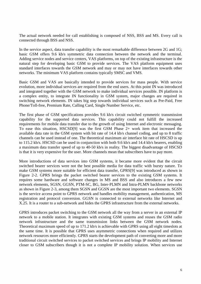
Figure 2-6: 3G Network (3GPP R4) 3GPP R5 continues the evolution as shown in Figure 2-7. The largest new functionality of R5 is IMS implementation including interworking with CS. GERAN/UTRAN interfaces will evolve to Iu for both PS and CS domains. CAMEL will be supported in IMS and more services will be converted to the PS side from the CS side. All traffic flow through the UTRAN can be IP based. The major change will be the transport technology, which will be converted from ATM in 3GPP R99 implementation to IP in 3GPP R4 and R5 implementation scenarios. The selection of using ATM, IP or both is flexible. The target of the 3G CN will be completely IP based as illustrated in Figure 2-8. IP based services such as VoIP and MMS will be available via IMS. The connection with traditional networks will be implemented through IMS. The HSS provides enhanced features
11
and functionalities for support IMS, and contains the subset of HLR/AuC functionality required both the PS and CS domains.
Iu
N M S
U m
M G W M G W
C N C S D o m ain M S
P S TN C S P D N
IS D N
G G S N S G S N
C N P S D o m ain
IP , M u ltim ed ia
G E R AN
B TS B S C
U TR AN
B S R N C
U u
U E
H S S (H LR /A u C )
& E IR
V A S
C A M E L
W A P
M E X E
O S A
U S A T
V H E
V LR /M SC S erver
G M S C S erver
IM S
IP /A TM
IP /A TM
IP /A TM
Figure 2-7: 3G Network (3GPP R5)
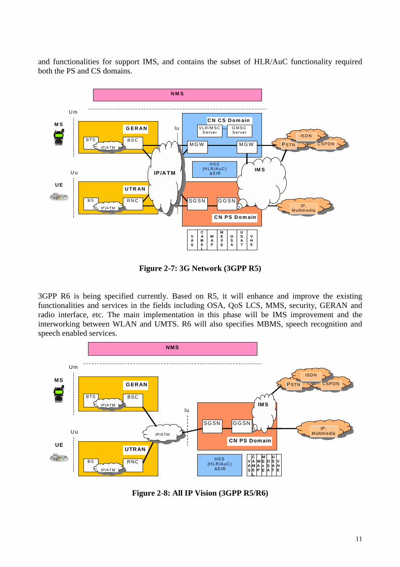
3GPP R6 is being specified currently. Based on R5, it will enhance and improve the existing functionalities and services in the fields including OSA, QoS LCS, MMS, security, GERAN and radio interface, etc. The main implementation in this phase will be IMS improvement and the interworking between WLAN and UMTS. R6 will also specifies MBMS, speech recognition and speech enabled services.
Iu
NMS
Um
MSPSTN CSPDN
ISDN
IP, Multim edia
GERAN
BTS BSC
UTR AN
BS RNC
Uu
UE
HSS (HLR/AuC)
&EIR
V A S
CAMEL
WAP
MExE
O S A
USAT
V H E
GGSN SGSN
CN PS Dom ain
IMS
IP/ATM
IP/ATM
IP/ATM
Figure 2-8: All IP Vision (3GPP R5/R6)

12
3 UMTS Architecture As mentioned in previous section, the main components of a UMTS system are, UTRAN, CN, UE and NMS. Among them NMS is a vendor specific component. This section mainly discusses the architecture of the first three components.
3.1 UTRAN UTRAN is located between the two open interfaces, Uu and Iu. It is the “revolutionary” part of the UMTS system. It offers the tools necessary to manage and control the WCDMA radio resources. It further includes the functionality needed to handle handover. The main task of UTRAN is to create and maintain RAB for communications between UE and the CN, and fulfills end-to-end QoS services. The architecture of UTRAN is given in Figure 3-1. A UTRAN is composed of multiple RNSs, and each RNS contains one RNC and a collection of BSs. The RNSs are connected through an open interface Iur, which carries both signaling and traffic information.
Figure 3-1: UTRAN architecture
BSs are located between the interfaces, Uu and Iub. The main tasks BSs are to establish the physical implementation of the Uu and Iub interface by utilizing the protocol stacks specified for them. The BSs implement WCDMA radio access channels and transfer information from transport channels to the physical channels based on the arrangement determined by the RNC. RNC schedules the transmission over the radio interface and takes care of handover. The concrete structure and implementation of BS is very complicated, which is presented in [10]. The RNC is located between the Iub and Iu interfaces, it acts as a switching and controlling element in the UTRAN. The third interface of it is Iur, which is used for inter-RNC connections. RNC also
Uu
RNS
RNS(UE) Core Network
Iu
UTRAN
(CN)
RNC
Iur
BS
BS
RNC
BS Iub
BS
Iub

13
has another interface, which is vendor specific, for the connections to/from NMS. The generic structure of RNC is shown in Figure 3-2.
Iur
I N T E RFACE
UN I TS
I N T E RFACE
UN I TS
(Wideband) Switching
UTRAN Control
Functions
Radio Resource
Management
O&M Interface
To/from the BSs
Iub
To/from
NMS
To/from Other RNCs
To/from
Core Network
Iu
Figure 3-2: RNC logical structure [10] The overall functionality of RNC can be classified into Radio Resource Management (RRM) and UTRAN control functions. The RRM is located in both UE and RNC. It contains a collection of algorithms including handover control, power control, admission control and packet scheduling, and code management. They are used to stabilize the radio path and fulfill the QoS set by the service using the radio path. The UTRAN control functions include all the functions related to set-up, maintenance and release of the RBs including the support functions for the RRM algorithms. These functions are System information broadcasting, Radio access and signaling bearer set-up, RB management, UTRAN security functions, UTRAN level mobility management, Database handling, and UE positioning as described in [10].
3.2 UMTS Core Networks The UMTS CN is located between the access networks and the external networks. It is the basic platform for all communication services provided to the UMTS subscribers. The PS and CS services are two basic communication services provided by the CN, other value added services are provided on top of these two basic services. UMTS CN provides universal services by aiming to handle a wide set of different radio accesses, WCDMA-FDD RAN, WCDMA-TDD RAN, MC-

14
CDMA RAN, GERAN, BRAN, Wireless LAN etc. The development of UMTS CN is an evolution process, which evolves from GSM and transfers to “All IP” gradually in different phases. 3GPP R99 implementation The 3GPP R99 implementation of UMTS introduces WCDMA as radio access and effectively utilizes existing GSM/GPRS system providing the basic communication services for both CS and PS traffic together with a rich set of VAS and supplementary services. The CN is divided into CS domain and PS domain for handling circuit switched and packet switched traffic respectively. The CN architecture of 3GPP R99 implementation is shown in Figure 3-3.
BSS
BSC
RNS
RNC
R99 CN
Node B Node B
A IuPS
Iur
Iubis
Uu
MSC SGSN
Gs
GGSN GMSC
Gn HLR
Gr
Gc C
D
E
AuC H
EIR
F Gf
Gi PSTN
IuCS Gb
VLR B
Gp
VLR G
BTS BTS
Um
RNC
Abis
MSC
B
PSTN PSTN
cell
interfaces supporting user traffic interfaces supporting signalling
Figure 3-3: CN architecture of 3GPP R99 implementation [3]
The CS domain contains 3G MSC/VLR and GMSC. These two elements can be physically separated or combined. The 3G MSC/VLR evolves from GMS MSC/VLR by merging the transcoders required for speech coding conversion from the radio network to MSC/VLR. The VLR is an integral part of the MSC in 3G. The 3G MSC/VLR is responsible for CS connection management activities, MM related issues such as location update, location registration, paging and security activities. The GMSC takes care of the incoming/outgoing connections to/from the external

15
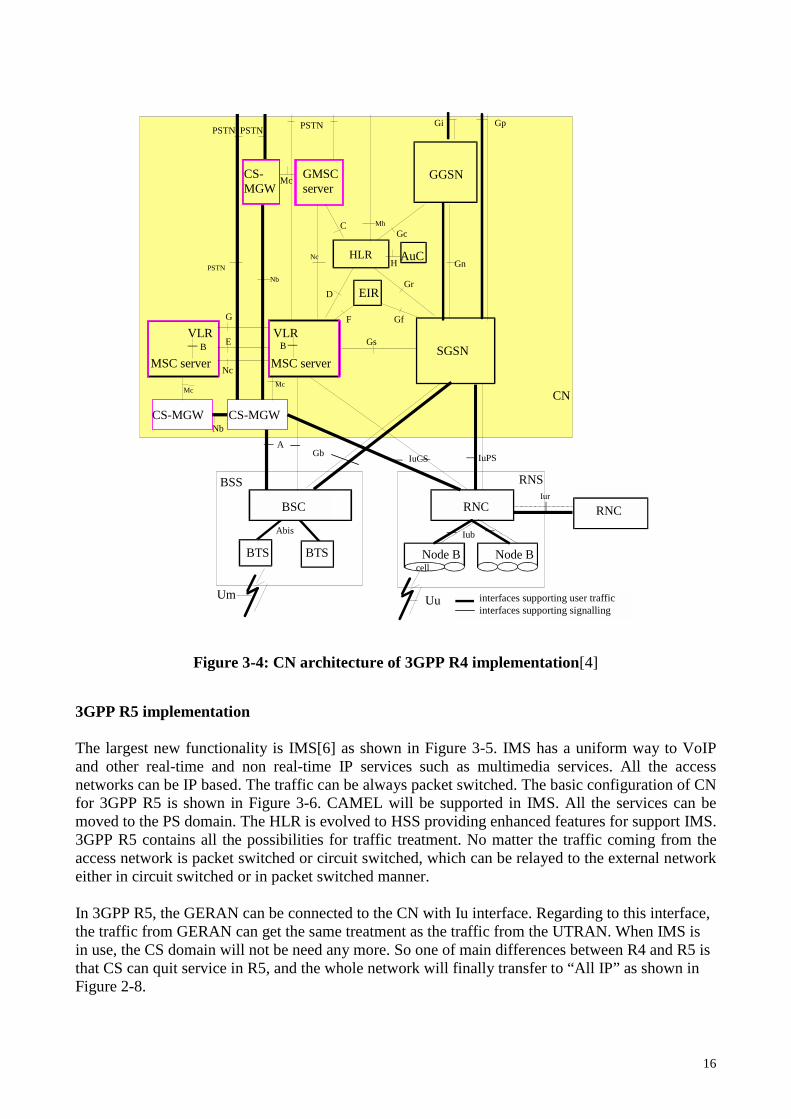
networks. It initiates a location info retrieval procedure to find the correct 3G MSC/VLR for call path connection, and establishes a call path towards the 3G MSC/VLR under which the addressed subscriber is to be found. The PS domain contains SGSN and GGSN. The SGSN node supports packet communication towards the access networks via the Gb interface for GSM BSS and Iu interface for UTRAN. SGSN mainly takes care of MM related issues such as route update, location registration, packet paging and security. The GGSN node maintains the connections towards external packet switched networks such as Internet. This node is responsible for route info retrieval and routing packets to/from SGSN for further relaying. It also takes care of session management. The Registers part is composed of EIR, HLR and AuC. This part does not deliver traffic. Instead it contains addressing and identity information required for MM and security for both CS and PS. HLR contains permanent data of the subscribers and is responsible for MM related procedures. AuC is a database generating the Authentication Vectors that contain the security parameters used for security activities performed over the Iu interface by the VLR and SGSN. AuC can be an integrated part of HLR and use MAP protocol interface for information transfer between them. EIR contains the identification information related to the UE. The CS domain of 3G CN uses GSM inherited signaling scenarios based MAP covering any possible addins that the UMTS brings into the system. The inherited interfaces follow the same functioning principles as used in GSM and are marked with MAP interface naming rules. The PS domain is evolved from GPRS. The inherited interfaces are marked with starting letter G followed by the small letter of the corresponding interface in the CS domain. 3GPP R4 implementation Compared to R99, the changes are extended remarkably to CN instead of in the radio access network. Especially in the CN CS domain, the MSC/VLR and GMSC are evolved into (G)MSC server and MGW to separate CM and actual switching as well as related functions into separate physical entities as shown in Figure 3-4. The MSC/GMSC server is evolved from the MSC/GMSC. It mainly comprises the call control and mobility control parts of a MSC/GMSC. Whole connection process is controlled by the (G)MSC server(s), user data goes through MGWs, which maintain the connection and act as switches. The MSC server contains CM main functionality and takes care of MM. VLR is also integrated into it. The MGW contains the functionality of performing actual switching and network inter-working. It may contain other functionality such as performing circuit packet conversion in VoIP calls, etc. The relationship between MSC/GMSC server and MGW is one to multiple. It means that one MSC/GMSC server can control numerous MGWs. The number of MGWs under one MSC/GMSC server is scalable and the MSC server amount may be dimensioned in the system.
16
BSS
BSC
RNS
RNC
CN
Node B Node B
IuPS
Iur
Iub
Uu
MSC server SGSN
Gs
GGSN GMSC server
Gn HLR
Gr
Gc C
D
Nc
H
EIR
F Gf
Gi PSTN
IuCS
VLR B
Gp
VLR
G
BTS BTS
Um
RNC
Abis
MSC server
B
PSTN
cell
CS-MGW CS-MGW
CS-MGW
AuC
Nb
Mc Mc
Nb
PSTN PSTN
Nc
Mc
Mh
A Gb
E
interfaces supporting user traffic interfaces supporting signalling
Figure 3-4: CN architecture of 3GPP R4 implementation[4]
3GPP R5 implementation The largest new functionality is IMS[6] as shown in Figure 3-5. IMS has a uniform way to VoIP and other real-time and non real-time IP services such as multimedia services. All the access networks can be IP based. The traffic can be always packet switched. The basic configuration of CN for 3GPP R5 is shown in Figure 3-6. CAMEL will be supported in IMS. All the services can be moved to the PS domain. The HLR is evolved to HSS providing enhanced features for support IMS. 3GPP R5 contains all the possibilities for traffic treatment. No matter the traffic coming from the access network is packet switched or circuit switched, which can be relayed to the external network either in circuit switched or in packet switched manner. In 3GPP R5, the GERAN can be connected to the CN with Iu interface. Regarding to this interface, the traffic from GERAN can get the same treatment as the traffic from the UTRAN. When IMS is in use, the CS domain will not be need any more. So one of main differences between R4 and R5 is that CS can quit service in R5, and the whole network will finally transfer to “All IP” as shown in Figure 2-8.

17
UTRAN
GERAN
PS CN
SGSN GGSN
HSS
CS CN MSC
Server GMSC Server
MGW MGW
IMS CN MGW
MGCF
BGCF S-CSCF
I-CSCF
P-CSCF
Iinternet & Corporate IP
PSTN/ISDN
BSC
RNC BS
BTS
Figure 3-5: Introduction of IMS (3GPP R5)
BSS
BSC
RNS
RNC
CN
Node B Node B
IuCS IuPS
Iur
Iub
Uu
M SC server SGSN
Gs
GGSN GM SC server
Gn HSS (HLR,AuC)
Gr
Gc C
D
E
EIR
F Gf
Gi PSTN
IuCS IuPS
VLR B
Gp
VLR G
BTS BTS
Um
RNC
Abis
M SC server
B
PSTN
cell
CS-M GW CS-M GW
CS-M GW
Nb
M c M c
Nb
PSTN PSTN
Nc
M c
A Gb
Go
Nc
interfaces supporting user traffic interfaces supporting signalling
Figure 3-6: Basic configuration CN (3GPP R5 implementation)[5]

18
The configuration of IMS is illustrated in Figure 3-7. All the functions can be implemented in different logical nodes. Two or more logical nodes are implemented in the same physical node.
P-CSCF
IM Subsystem
CSCF MGCF HSS
Cx
IP Multimedia Networks
IMS-MGW
PSTN
Mn
Mb
Mg
Mm
MRFP
Mb
Mr
Mb
Legacy mobile signalling Networks
CSCF
Mw
Go
Mw
Gm
BGCF Mj Mi
BGCF
Mk Mk
C, D, Gc, Gr
UE
Mb
Mb
Mb
MRFC
SLF Dx
Mp
PSTN
PSTN
CSCF: Call Session Control Function MGCF: Media Gateway Control Function P-CSCF: Proxy CSCF IMS-MGW: IMS Media Gateway Function S-CSCF: Serving CSCF MRFC: Multimedia Resource Function Controller I-CSCF: Interrogating CSCF MRFP: Multimedia Resource Function Processor SLF: Subscription Locator Function BGCF: Breakout Gateway Control Function PDF: Policy Decision Function
Figure 3-7: Configuration of IM Subsystem entities[5] The CSCF can act as P-CSCF, S-CSCF or I-CSCF. The P-CSCF is the first contact point for the UE within the IMS; the S-CSCF actually handles the session states in the network; the I-CSCF is mainly the contact point within an operator’s network for all IMS connections destined to a subscriber of that network operator, or a roaming subscriber currently located within that network operator’s service area. The MGCF controls the parts of the call state that pertain to connection control for media channels in an IMS-MGW. It communicates with CSCF, selects the CSCF depending on the routing number for incoming calls from legacy networks, and performs protocol conversion between ISUP and the IM subsystem call control protocols. A IMS-MGW terminates bearer channels from a circuit switched network and media streams from a packet network. It supports media conversion, bearer control and payload processing, and interacts with the MGCF for resource control.

19
The MRFC controls the media stream resources in the MRFP and interprets information coming from an application server and S-CSCF. The MRFP controls bearers on the Mb interface and provides resources to be controlled by the MRFC. It sources and processes media streams. The BGCF selects the network in which PSTN breakout is to occur and selects the MGCF. The SLF is queried by the I-CSCF during the Registration and Session Setup to get the name of the HSS containing the required subscriber specific data. It is also queried by the S-CSCF during the Registration. The architecture shall be based on the principle that the service control for Home subscribed services of a roaming subscriber is in the Home network, e.g., the S-CSCF is located in the Home network The IMS service concept for roaming users is illustrated in Figure 3-8. The services can be provided via the service platform in the Home Network or via an external service platform located in either the visited network or in a third party platform. The third party access to IMS services is secured via OSA framework. The P-CSCF is located in the same network (home/visited network) as the GGSN. It enables the session control to be passed to the S-CSCF, which is located in the home network and invokes service logic. A P-CSCF is supported in both roaming and non-roaming case, no matter the S-CSCF is located in the same IMS CN or not.
UE
P-CSCF
Serving CSCF
Home Network
Home/Visited Network
Service Platform
Gm
Mw External Service Platform
Figure 3-8: IMS service (VHE)[6]

20
3.3 UMTS Terminals A user terminal in UMTS corresponding to MS in GSM is called UE, which is responsible for the communication functions needed on the radio interface. A UE need to support followings: Mandatory functions[10]
• An interface to UICC for insertion of USIM • Service provider and network registration and deregistration • Location update • Originating and receiving services in both connection-oriented and connectionless manner • A permanent IMEI • Basic identification of the terminal capabilities • Support for emergency call without USIM • Support for the execution of algorithms required for authentication and encryption
Supplementary functions[10]
• An API capacity • A mechanism to download service related information, new protocols, other function and
even new APIs into the terminal • Maintenance of VHE using the same user interface and or another interfaces while roaming • Optional use of multiple UICCs
The UE consists of a set of interconnected modules, USIM, TE and ME, as shown in Figure 3-9.
R
USIM
TE
User’s application
TA
M E
M T Tu
RT
NT UICC
Iu
Cu
UE
Another User’s
Application
End-to-end interface
DTE
H om e N etw ork
UTRAN
Serving N etw ork
T ransit N etw ork
Figure 3-9: UE reference architecture[10]

21
USIM is the user dependent part. It is implemented into UICC. USIM is connected to a specific user profile but service profile. The operator will provide the information content of USIM while a user makes the subscription. The counterpart in network side is basically user’s home network registers such as HLR and AuC. ME is a user’s subscription independent part of UE. It terminates all control plane functions and UMTS bear for user plane. ME contains the TA function and MT module. MT terminates the radio transmission, adapts terminal equipment capabilities to those of the radio transmission, terminates the services of the UMTS network systems, and has the capabilities of changing locations within access network or moving between different access networks. NT is the core network dependent part of MT, it uses non access stratum protocols for mobility management and communication management. The RT is radio access dependent part of MT, which terminates the UTRAN services. TE is the telecom service platform dependent part of UE, which provides end-user application functions. TE interacts with MT via the TA function. UMTS terminals classification The diverse requirements such as simultaneous multi-network and multi-radio mode MT, narrowband and wideband services, real-time and non real-time services, security and confidentiality, rich applications and functionalities, etc. for UMTS terminals increase the complexity and cost for the UE. If the cost for the UE is too high it will prevent the expanding of 3G technologies and increase the risk in implementation of UMTS network. To fulfill needs for different group of users, it is essential to classify UMTS terminals based on both termination functions and subscribers and their needs as Table 3-1. The concrete models of the terminals can be based on different combinations between the two types of classifications. Table 3-1: Classification of UMTS Terminals
Classification based on MT’s capability
Classification based on subscribers and their needs
Single radiomode MT
Can utilize only one type of radio interface for user traffic.
Classic terminal
Equivalent to the present sellular phone, able to handle both GSM and WCDMA rado access but not necessarily simultaneously
Multi-radiomode MT
Can use several radio termiantions for user traffic.
Dual mode
Contains both GSM and WCDMA radio access and can automatically select the access method based on available coverage and requested service.
Single network MT
Can use only one type of core network, PS, CS or PS/CS.
Multimedia terminal
Combination of cellular phone and palm/laptop, contains plenty of applications to handle the multimedia connections and services.
Multi-network MT
Support several core networks such as both the UMTS core network and GSM. NSS
Special terminals
Serve special purposes such as positioning, etc. and will be integrated together with other equipment.
UMTS subscription As GSM, UMTS separates the subscription, USIM, from the ME. It is contained in the removable UICC that the USIM with service information and identities, administrative data, temporary network data, service related data, personal data and applications. The USIM is accessed through profiles defining how the services and stored information will be provided to the user. One USIM

22
can contain multiple profiles for different purposes, and both the user and the network can change the setting of the profiles. The network changes the profiles via MExE. The main difference between GSM SIM and UMTS USIM is that USIM is downloadable and its information is accessible and updateable.
4 UMTS Protocols There are two major protocol design aspects in UMTS, one is the separation of generic transport aspect from UMTS specific mobile networking aspect by horizontal layers, the other is the separation of network control aspect from the user data transfer aspect by vertical planes as shown in Figure 4-1. Correspondingly, the UMTS protocol model is divided into three layers, transport network layer, radio network layer and system network layer, in horizontal decomposition and two planes, control plane and user plane, in vertical separation. The horizontal layers depict the protocol interworking across multiple interfaces and protocol terminations. The transport network layer provides transport services for all UMTS network elements thus making them able to communicate across different interfaces. The radio network layer is responsible for the interworking between UE and CN on all radio bearer related aspects. The system network layer protocols extend from UE to the transit network edge of the UMTS CN and take care of the interworking of UMTS communication service related aspects. The vertical planes illustrate the system control and user data flow in the UMTS system. The control plane protocols in different UMTS system interfaces interwork with each other to make system-wide control of communication resources and services. The user plane protocols interwork each other across the different interface to ensure the end-to-end flow of user data.
Uu Iub Iu E / Gn
User Plane Control Plane
User Plane Control Plane
Control Plane User Plane
System Network Layer
Radio Network Layer
Transport Network Layer
UE BS RNC MSC/VLR SGSN SMSC GGSN
Figure 4-1: UMTS protocol internetworking architecture[10]

23
4.1 Uu Interface Protocol The key task of the radio interface is multiplexing different kinds of traffic flows from different origins. To have effective control of multiplexing, a three-layer model is applied to it as illustrated in Figure 4-2. In this model, the radio interface is divided into three protocol layers, physical layer (L1), the data link layer (L2) and network layer (L3). L1 provides its services as a set of WCDMA transport channels. It takes care of the first level multiplexing function to map the traffic flows between transport channels and physical channels and vice versa. L2 is split into different sublayers, MAC, RLC, PDCP and BMC. It is another multiplexing layer and contributes to dynamic sharing of the capacity of the WCDMA radio interface. MAC controls the use of transport block capacity. RLC adds regular link layer function onto the logical channels provided by the SAP between RLC and MAC. PDCP makes the UMTS interface applicable to carry IP data packets. BMC is specified for message broadcast and multicast domain. L3 and RLC are divided into Control and User planes. PDCP and BMC exist in the User plane only. L3 control plane is the RRC protocol taking care of radio resource management. An RRC entity locating on both UE and UTRAN sides has control interfaces with all other protocol entities. The MM and SS/CC/SM protocols are located on top of L3. MM is responsible for mobility management, SM controls the establishment and release of packet transfer sessions or PDP contexts in the CN PS domain, CC takes care of the establishment and release of circuit switched calls in the CN CS domain, SS controls the activation and deactivation of various call related or non-call related supplementary services.
L 3
cont
rol
cont
rol
cont
rol
cont
rol
Log ical C hannels
T ransport C hannels
C -p lane signalling U -plane in form ation
P H Y
L 2/M A C
L 1
R L C L 2/R L C
M A C
R L C R L C
R L C R L C
R L C R L C
R L C
B M C L 2/B M C
contro l
P D C P P D C P L 2/PD C P
R adio B earers
R R C
Figure 4-2: Radio Interface protocol architecture (SAPs marked by circles) [9]

24
4.2 Protocol Architecture of Main Interfaces across UMTS The protocol architecture in the main interfaces from UE to ISP across the UMTS network for packet switched traffic is illustrated in Figure 4-3 and 4-4. Figure 4-3 illustrates the protocol stacks in the user plane. Figure 4-4 illustrates the protocol stacks in the control plane, and it also presents the control protocol stacks between HLR and SGSN, GGSN, MSC. The control protocol stack between MSC and SGSN is also illustrated in this Figure. From the UE to UTRAN (RNC), the IP data packets are carried in PDCP packets. PDCP provides either an acknowledged/unacknowledged or transparent transfer service. It also performs a compression/decompression function. From the UTRAN (RNC) to SGSN IP packets are tunneled using GTP-U. Another GTP-U tunnel then runs from the SGSN to GGSN. Using GTP-U, UMTS can carry a number of different packets such as IPv4, IPv6, PPP and X.25 over a common infrastructure. GTP-U packets are formed by adding a header to the underlying PDP packet and sent using UDP over IP using IP address of the tunnel end point, e.g, the GGSN for traffic sent from the SGSN to an external network. In UMTS CN, IP Layer 3 routing is typically supported by ATM switching networks. It is the operator’s choice to implement QoS at the IP or ATM level. The communication resources and services in UMTS are controlled via the protocols located in the control plane. The GTP-C protocol takes care of the setting up, modifying, and tearing down of GTP tunnels. It runs between SGSN and GGSN and also carries the messages to set up and delete PDP contexts. GTP-C does not run over Iu interface between UTRAN (RNC) and SGSN. The GTP tunnel from UTRAN (RNC) to SGSN is setup by part of RANAP, which provides the signaling across Iu interface and is also responsible for:
• Radio access bear setup, modification and release • Control of the UTRAN security modes • Management of RNC relocation procedures • Exchanging user information between RNC and CN. • Transport MM and CC information between UE and CN.
Through Uu interface, the RRC sets up a signaling connection from UE to RNC. It covers the assignment, re-configuration and release of radio resources. RRC also handles handover, cell re-selection, paging updates, and notifications. UMTS can support both IPv4 and IPv6 operations. It decouples the terminal packet data protocol from the network transport through the use of tunneling and can transport IPv4 and IPv6 packets without modification. The underlying UMTS CN can also be IPv4 or IPv6 networks, and it has no interaction with the user data being tunneled over it.

25
User Plane (Traffic Plane)
TE
IP
PPP
L1
MT UTRAN ATM
switch
ATM ARP
server
AAL5
ATM
ATM ARP
server
SGSNGGSN
IP
GTP-U UDP
IP
IPOA
AAL5
ATM
IPinIP
IP
802.3
FE
GGSN
Application
IPinIP
IP
L2
L1
ISP
Relay
GTP-U UDP
IP
IPOA
AAL5
ATM
GTP-U UDP
IP
IPOA
AAL5
ATM
Relay
GTP-U UDP
IP
IPOA
AAL5
ATM
PDCP
RLC
MAC
Radio
Relay
PPP
L1
PDCP
RLC
MAC
Radio
Relay
Application
Figure 4-3: UMTS user plane protocol stack Control Plane (Signaling Plane)
TE
PPP
L1
PPP
L1
MT UTRAN
SM/
GMM
RRC
RLC
MAC
Radio
RRC
RLC
MAC
Radio
RANAP
SCCP
MTP3
AAL5
ATM
Replay
ATM switch
ATM ARP
server
AAL5
ATM
ATM ARP
server
SM/
GMM RANAP
SCCP
MTP3
AAL5
ATM
GTP-C
UDP
IP
IPOA
AAL5
ATM
SGSNGGSN
GTP-C
UDP
IP
IPOA
AAL5
ATM
BSSAP+/
MAP TCAP
SCCP
MTP3
MTP2
E1
DHCP/
RADIUS UDP
IP
802.3
FE
GGSN MSC _VLR /HLR
DHCP/
RADIUS UDP
IP
L2(802.3)
L1(FE)
ISP
MAP
TCAP
SCCP
MTP3
MTP2(SAAL)
E1(ATM)
GGSNHLR
MAP
TCAP
SCCP
MTP3
MTP2(SAAL)
E1(ATM)
SGSNHLR
BSSAP+
TCAP
SCCP
MTP3
MTP2(SAAL)
E1(ATM)
SGSNMSC_HLR SM: Session management GMM: GPRS mobility management RRC: Radio resource control RLC: Radio Link Control MAC: Medium Access Control RANAP: Radio Access Network Application Protocol SCCP: Signaling Connection Control Part MTP3/2: Message Transfer Part 3/2 PDCP: Packet Data Convergence Protocol
SAAL: Siganaling ATM adaptation layer AAL5: ATM adaptation layer 5 GTP-C/U: GPRS Tunneling Protocol-Control/User IPoA: IP over ATM UDP: User Datagram Protocol BSSAP: Base Station System GPRS Application Part MAP: Mobile Application Part TCAP: Transaction Capabilities Application Part PPP: Point to Point Protocol
Figure 4-4: UMTS control plane protocol stack

26
5 UMTS Services The business or value chain in UMTS consists of end user, carrier provider, service provider and content provider. Carrier provider is the party maintaining both access network and CN; service provider is the one providing service(s); content provider is a party creating and providing the end user services. In real life, one or more parties could be the same commercial party, for example the service provider and carrier provider are often the same company and also acts as service provider to some extend. A UMTS network is a platform required to provide bit rate above 144 kb/s within coverage area for both circuit and packet switched connections as shown in Table 5-1. Table 5-1: UMTS bit rates [10] Circuit switched bit rate Packet switched bit rate Coverage type 144 kb/s 384 kb/s 2 Mb/s
144 kb/s (peak) 384 kb/s (peak) 2 Mb/s
Basic coverage, rural/suburban, fast moving vehicles, outdoor Extended coverage, urban, moving vehicles, outdoor Hot spot areas, center, walking speed, indoor
In UMTS system, bandwidth is one factor affecting required services, but the more important issues are the utilization and verification of UMTS bearers via QoS mechanisms.
5.1 UMTS QoS Architecture The end-to-end services are carried over the UMTS network with bearers providing QoS as shown in Figure 5-1. As shown in Figure 5-1, the UMTS system contains multiple levels and entities of bearer services with their own special characteristics. The local service contains the mechanisms on how the end-user service is mapped between TE and MT. UMTS bearer service contains mechanisms to allocate QoS over the UMTS/3G network. The external bearer service handles the QoS of UMTS network towards the external networks. The end-to-end service sets the requirements for QoS. These requirements are mapped to the next levels performing QoS, they are classified as:
• Conversational class: minimum fixed delay, no buffering, symmetric traffic, guaranteed bit rate.
• Stream class: minimum variable delay, buffering allowed, asymmetric traffic, guaranteed bit rate.
• Interactive class: moderate variable delay, buffering allowed, asymmetric traffic, no guaranteed bit rate.
• Background class: big variable delay, buffering allowed, asymmetric traffic, no guaranteed bit rate.

27
TE MT UTRAN CN Iu EDGE NODE
CN Gateway
TE
UMTS
End-to-End Service
TE/MT Local Bearer Service
UMTS Bearer Service External Bearer Service
UMTS Bearer Service
Radio Access Bearer Service CN Bearer Service
Backbone Bearer Service
Iu Bearer Service
Radio Bearer Service
UTRA FDD/TDD
Service
Physical Bearer Service
Bearer Service Physical
Figure 5-1: UMTS QoS Architecture[10] In UMTS, the important QoS parameters are maximum bit rate, guaranteed bit rate, allowed transfer delay and the required QoS class is negotiable or not. The attributes of UMTS bearer service and radio access bearer service for each UMTS QoS class are given in Table 5-2 and 5-3. Table 5-2: UMTS bearer service attributes[10] Conversational Streaming Interactive Background Maximum bit rate (kb/s) Guaranteed bit rate (kb/s) Symmetry Transfer delay (ms)
< 2048 < 2048 Symmetric 100-250
< 2048 < 2048 Asymmetric 250-seconds
< 2048 N/A Asymmetric N/A
< 2048 N/A Asymmetric N/A
Table 5-3: UMTS radio access bearer service attributes[10] Conversational Streaming Interactive Background Maximum bit rate (kb/s) Guaranteed bit rate (kb/s) Symmetry Transfer delay (ms)
< 2048 < 2048 Symmetric 80-250
< 2048 < 2048 Asymmetric 250-seconds
< 2048 N/A Asymmetric N/A
< 2048 N/A Asymmetric N/A

28
From Table 5-2 and 5-3, the main difference between QoS classes is transfer delay. In UMTS system the majority traffic is expected to be packet switched. The packet switched connections do not use fixed bit rates, which varies according to the transmission direction. The relations among QoS classes, transfer delay, required network resources (investment), and required buffer resources are shown in Figure 5-2.
Required Buffering
Resources
Stre
amin
g C
lass
Con
vers
atio
nal
Cla
ss
Required Network
Resources (Investment)
Back
grou
nd
Cla
ss
In
tera
ctiv
e
Cla
ss
Delay
Reasonable area
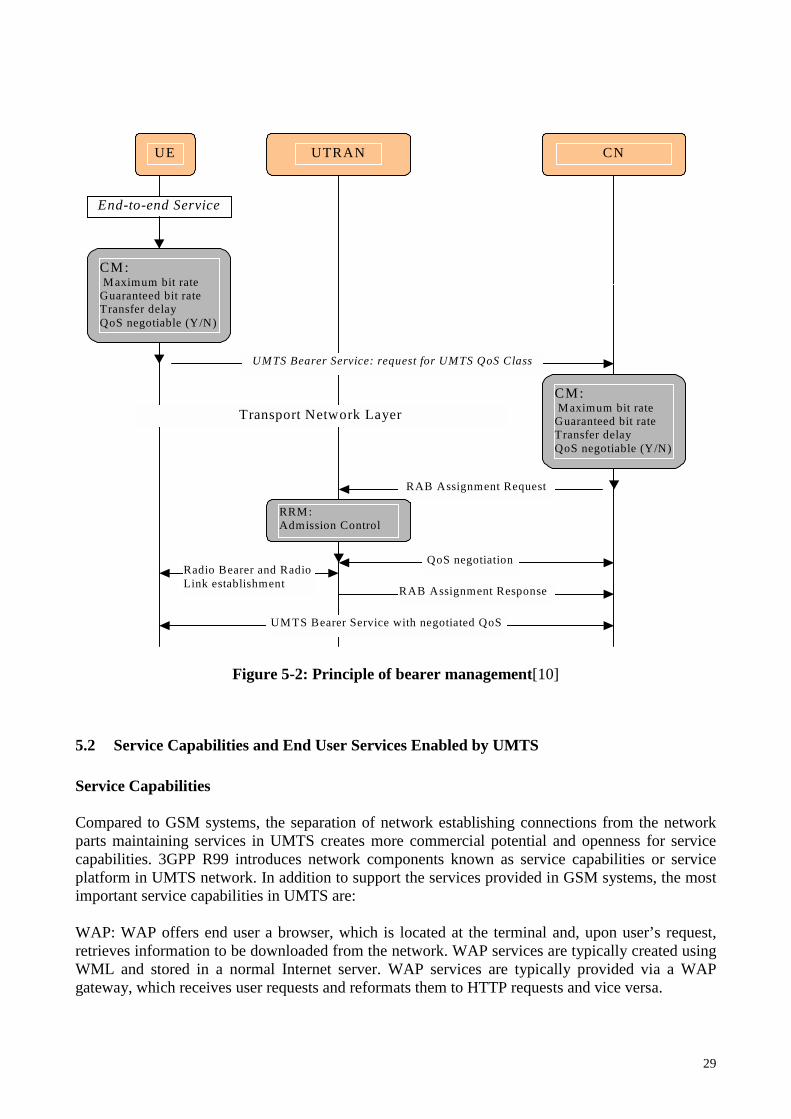
Figure 5-2: Relations between required network resources and QoS[10] Figure 5-2 illustrates the principle of bearer management. At the UE side, the end-to-end service is initiated, the requested service is classified based on the service class criteria CM, and the UMTS bearer establishment request is passed to CN within RRC and RANAP message through UTRAN. At the CN side, the end-to-end service is mapped onto a UMTS bearer based on the defined QoS attributes by CM, the UMTS bearer requirements are checked, and then the RAB allocation and QoS negotiation are handled between UTRAN and CN. Finally the UMTS service with negotiated QoS is established between UE and CN.
29
End-to-end Service
Transport Network Layer
UE UTRAN CN
CM: Maximum bit rate Guaranteed bit rate Transfer delay QoS negotiable (Y/N)
CM: Maximum bit rate Guaranteed bit rate Transfer delay QoS negotiable (Y/N)
UMTS Bearer Service: request for UMTS QoS Class
QoS negotiation
RAB Assignment Request
RRM: Admission Control
Radio Bearer and Radio Link establishment RAB Assignment Response
UMTS Bearer Service with negotiated QoS
Figure 5-2: Principle of bearer management[10]
5.2 Service Capabilities and End User Services Enabled by UMTS Service Capabilities Compared to GSM systems, the separation of network establishing connections from the network parts maintaining services in UMTS creates more commercial potential and openness for service capabilities. 3GPP R99 introduces network components known as service capabilities or service platform in UMTS network. In addition to support the services provided in GSM systems, the most important service capabilities in UMTS are: WAP: WAP offers end user a browser, which is located at the terminal and, upon user’s request, retrieves information to be downloaded from the network. WAP services are typically created using WML and stored in a normal Internet server. WAP services are typically provided via a WAP gateway, which receives user requests and reformats them to HTTP requests and vice versa.

30
MExE: MExE is specified by 3GPP to enable provision of standardized execution environment in UE. It provides the ability to negotiate the UE supported capabilities with a MExE service provider. The applications can be developed independent of any UE platform or operator’s service platform and executed on a remote server or downloaded to the UE and directly executed in it. USAT: Compared to GSM SIM, USIM has more memory space and more processing power. It creates room for new kinds of services presented in USIM. 3GPP designed USAT to provide a standardize execution environment for applications stored on the USIM card. USAT provides mechanisms enabling the applications to interact with any mobile equipment supporting the specified mechanisms thus ensuring the interoperability between USIM and UE. The applications are downloadable and can be updated. CAMEL: CAMEL is specified by ETSI/3GPP, which is a technology of GSM phase 2+, which enables roaming GSM users to access IN service in their home operator’s environment. In UMTS, CAMEL is used to enable mobility and service portability on top of IN. Like in IN, CAMEL takes care of CS connection control. In UMTS, it will perform interworking with PS connections. Service creation in 3G is based on VHE including CAMEL, OSA and MExE. CAMEL will interoperate with most of the services such as SMS, MM, GPRS interworking, CS call control, LCS, etc. in UMTS. VHE: VHE is specified by 3GPP, it is a concept of the 3G mobile system for personal service environment portability across network boundaries and between terminals. The user can have the same interface and service environment regardless of location. For certain subscriber, his/her profile(s), charging information, service information and numbering information is either transferred or is transparently available between networks. The concept can be realized using OSA, MExE, CAMEL or USAT. OSA: OSA is the standardization effort of 3GPP. It specifies the architecture that enables applications to make use of network functionality through open standardized interfaces. OSA consists of applications implemented in applications servers, framework providing applications with basic mechanisms for using service capabilities in network, and service capability servers providing applications with service capability features. Positioning/LCS: Positioning service is also called LCS in 3GPP specifications[2]. The typical commercial position based applications are fleet management, traffic information management, transportation, nearest services, emergency services, following me services, etc. Various methods can be used to find geographic position of a mobile terminal. After detailed investigation and discussion in 3GPP, following positioning methods were selected for UMTS networks:
• Cell ID based positioning: The position of the terminal can be estimated using the cell related position information on which radio cell the terminal is visiting or has just been visited. By using the cell ID or cell coverage co-ordinates of the serving BS, the position of the terminal can be estimated.
• OTDOA positioning: OTDOA is based on TDOA of radio signals from neighboring BSs
observed by UE. The unknown UE position can be estimated by processing the measurements of TDOA between the UE and at least three BSs of known co-ordinates.

31
• GPS positioning: GPS estimates the position of a UE by measuring the delay between a group of satellites keeping precise timing and GPS receiver implemented in the UE. In the estimation process, at least three satellites are need. By calculating the distance between the GPS receiver and each satellite, the position of the UE can be estimated by utilizing mathematical method.
Among these three positioning methods, GPS is the most accurate positioning method. Its accuracy is 1~100m, but it is complex and expensive. Depending on the cell structure of the radio network, the positioning accuracy of OTDOA and Cell ID are 50~3000m and 100~15000m respectively. The positioning functionality of UMTS is distributed to the network elements. The positioning equipment and functionality is located in both UTRAN and CN. The UTRAN contains functionalities responsible for implementing positioning with the selected positioning methods and positioning data collection. In CN, a new network element, GMLC is added to the overall system architecture to support location services. It acts as a connection point through which the positioning data is delivered to other service capabilities and client applications. The detailed UMTS system architecture for positioning is presented in [10]. End User Service With the development of 3G, more and more applications are emerging for UMTS. There might never be a single killer application to monopolize the application markets. It is predictable that multiple and rich applications will coexist in the UMTS systems. The applications of 3G can be divided into different categories based on different criteria by different organizations and vendors. Table 5-5: The possible types of services in 3G networks Category Description
Fun WWW, video, post card, snapshots, text, picture and multimedia messaging, datacast, personalisation applications (ring tone, screen saver, desk top), jukebox, virtual companion, etc.
Work Rich call with image and data stream, IP telephony, B2B ordering and logistics, information exchange, personal information manager, dairy, scheduler, note pad, 2-way video conferencing, directory services, travel assistance, work group, telepresence, FTP, instant voicemail, colour fax, etc.
Media Push newspaper and magazines, advertising, etc. Shopping E-commerce, e-cash, e-wallet, credit card, telebanking, automatic transaction, auction, micro-
billing shopping, etc. Entertainment News, stock market, sports, games, lottery, gambling, music, video, concerts, adult content,
etc. Education Online libraries, search engines, remote attendance, field research, etc. Peace of mind Remote surveillance, location tracking, emergency use, etc. Health Telemedicine, remote diagnose and heath monitoring, etc. Automation Home automation, traffic telematics, machine-machine communication, etc. Travel Location sensitive information and guidance, e-tour, location awareness, time tables, e-
ticketing, etc. Add-on TV, radio, PC, access to remote computer, MP3 player, camera, video camera, watch, pager,
GPS, remote control unit, etc. UMTS Forum[11] divides the near-term 3G data services into content connectivity and mobility, which are subdivided into six categories of services as shown in Table 5-4.

32
No matter how the applications will be classified and what criteria will be used for the classification, the bottom line is that computer and Internet applications will be merged with communication and location based services. Many networks operators, vendors and third party service providers have been already creating many applications and demos. Though it is difficult to enumerate the concrete services in 3G networks, the possible types of services that will be available in 3G networks are listed in Table 5-5. Table 5-4: UMTS service categories and their applications
Service category
Applications Users Revenues (2010)
Mobile Intranet/ Extranet Access
• Messaging (E-mail), Travel assistance (WWW) • Mobile sales, Technical services • Teleworking, Access to corporate database • Video telephony, Conferencing • Fleet management, Warehaouse
Mobile office, Business user
15%
Mobile Internet Access
• Messaging (E-mail, SMS, MMS) • Download video, music, streaming • VoIP, Video over IP • m-banking • m-commerce (m-purchasing), trading • www travel • www Infoservices
Business user, Consumer
3%
Customized Infotainment
• Information (photo, video, music download) • www travel • Education (schools, universities) • Mobile messaging, Chatting (SMS, MMS) • Gaming • m-shopping, banking, e-wallet, micro-payment
Business user, Consumer
28%
Multimedia Messaging
• Extension of SMS • MMS: Image, Video, Unified messaging, Mobile
postcard, video/audio clip • MS Office document • Mobile chatting • Machine to machine communications • Photo messaging • Music • Video messaging
User 15%
Location-based Services
• Navigation (person car) • Localized Info (yellow pages) • Location-based m-commerce • Telematics • Trading (vehicle, goods, person)
User 3%
Rich Voice Telephony/Conferencing Video-telephony, conferencing, presence Telemedicine Teleworking (building industry etc.) Multimedia communication (IMS)
User 34%

33
In 3G, the services are created by 3rd parties, users, and operators and provided via service platforms by operators as shown in Figure 5-3.
New Applications Provided by 3rd parties, Users, Operators
Service Platforms
Service Categories provided by Operators
M-Office
Telematics
Dispatch Telemetry Gambling Banking Ticketing
Rich Voice LBS MMS Internet Access
Intranet Access
Info- tainment
Info- provisio
Personal Info Management
Video Conferencing
E-Pay Broking Advertising
Health Care
Map based Info
Music Video
Instant Messaging
Data Bearer /GPRS/MMS/xHTML/JAVA Download/IMS
Figure 5-3: Service provision in 3G networks [11]
6 UMTS Market This section presents the estimated market shares and predications for 3G and mobile communications based on publicly available information. From the information here, we can have an overall image for future UMTS market.
6.1 3G Market Shares Table 6-2 shows the estimation of WCDMA market shares based public information about UMTS contracts until late 2001. The actual situation may vary a lot. Anyway we can see the rough position of different players in the battle of pushing their UMTS products. Table 6-1 illustrates UMTS world’s estimation on 3G markets in different geographical areas. The vendors will battle for these markets for pushing their products and technologies. Table6-1: 3G (cdma2000 and WCDMA) market sizes around 2005[12]
Geographical Area Market Size Asia / Pacific Europe (East & West) Americas (North & South) Africa / Near East
~ 40% ~ 30% ~ 30% ~ several %

34
Table 6-2: Estimation of UMTS (WCDMA) sales volume market share (late 2001)[12] Vendors Market shares Ericsson Nokia Siemens (NEC) Nortel NEC (Siemens) Alcatel Lucent Motorola
33 % 32 % 15 % 8 % 4 % 4 % 3 % 1 %
Table 6-3 and 6-4 present the biggest GSM operators and mobile markets by number of subscribers respectively until 2002. These operators and areas are the potential investors and places for deploying UMTS first in the next several years. Table 6-3: Top 12 GSM Operators By Subscribers (June 2002) [12]
GSM Operator Subscribers in millions (June '02) China Mobile Vodafone Group T-Mobile China Unicom Orange AT&T Wireless Telecom Italia Mobile Singtel Cingular Telefonica Moviles mmO2 Turkcell
123 119 56 52 41 27 27 24 22 19 18 14
Note: These are carriers that operate GSM networks and have GSM customers, but these numbers represent the entire customer base, and not just GSM subscribers.
Table 6-4: Biggest Mobile Market[12]
Area Subscribers in millions Until China USA Japan Germany Italy United Kingdom France South Korea Spain Brazil
200.3 ~137 72.8 64.4 ~47 ~45 ~34 ~32 ~28 ~27
Dec 2002 June 2002 Nov 2002 July 2002 Late 2001 Late 2001 Late 2001 Late 2001

35
6.2 Vendors Products and Strategies Currently, many vendors have involved in UMTS systems development and deployment. The largest UMTS vendors are listed in Table 6-1. Currently it seems that no network vendor can supply all equipment and components to the full 3G networks. Quite a few of them are the main contractors to build 3G networks. Normally network vendors bring in partners in different areas such as services and applications providers, handset manufactures, etc. Since late 2002, the development and introduction of UMTS are more and more active though the economic situation is still dim. Many vendors announced launching of their UMTS products, and more operators introduced UMTS operations in reality. Following presents the main vendors’ UMTS products and their 3G related activities in last four months according to recent public information[11, 12]. Ericsson provides the whole range of 2G and 3G Mobile Systems and end-to-end system elements including infrastructure, terminals, applications and expertise. Who also provides total solutions from systems and applications to services and core technology for mobile handsets. With Sony Ericsson, Ericsson also provides complete mobile multi-media products. Ericsson is very active in 3G development and deployment. In October 2002, Ericsson announced to participate 3G expansion with J-PHONE in Japan, to jointly develop and supply WLAN access solutions for 2G and 3G networks with Agere and Promix, and to supply CDMA2000 1xEX-DO overlay system to Vesper in Brazil. In the same month, Ericsson also confirmed 10000 UMTS/WCDMA macro base stations were shipped worldwide. In December 2002, Ericsson and AT&T Wireless completed the first WCDMA/UMTS call in a live network in the Americas. Ericsson was also chosen as primary 3G supplier by Danish operator TDC Mobil, the delivery planned to start in January 2003. In January 2003, Ericsson agreed to deliver seamless 2G/3G WCDMA networks to Far EasTone in Taiwan, to supply new Video Gateway System to Hutchison globally, and to provide WCDMA network infrastructure to Tele2/Tango in Luxembourg and Liechstenstein. The latest activities of Ericsson are that it demonstrated mobile video call in a fully integrated dual-mode WCDMA/GMS platform, and was going to provide Orange UMTS core networks equipments and associated integrated services. Nokia provides the whole systems from terminals and base stations to core network solutions for GSM, GPRS and UMTS. The products spread in a wide range with various models. Nokia also provides all kinds of platforms for 3G systems. Nokia is also very active in 3G development and deployment. Nokia announced to participate in 3G expansion with J-PHONE in Japan and to supply WCDMA 3G network to CHT Taiwan in October 2002. In November 2002, Nokia announced that it had launched 15 phones supporting MMS and delivered the world’s first GSM/EDGE 3G mobile phone, 6200 tri-band (GSM/GPRS/EDGE 850/1800/1900 MHz) phone, for operator controlled live network testing, and successfully performed 3G WCDMA call handover to commercial GSM network with Vodafone in Italy. In December 2002, Nokia successfully demonstrated IP mobility services using Nokia’s IMS, which is expected to have the first commercial release in 2003, followed by IMS capable terminals in 2004. Nokia also demonstrated Service Area Identity (SAI) positioning technology in Radiolinja’s pre-commercial WCDMA network, and agreed to deliver WCDMA 3G Network to Taiwan Cellular

36
Corp. in December 2002. Until February 2003, Nokia has delivered 10,000 Nokia 6650 phones globally to operators for testing. The commercial deliveries are expected to start first half of 2003. Siemens in partnership with NEC provides UMTS radio solution (FDD and TDD), carrier-class switching for UMTS and many kinds of enabling services for 3G systems. Siemens shipped first U10 3G phones to selected operators in October 2002. In December 2002, Siemens agreed to supply and install all the necessary components of a complete 3G mobile network for P&T Luxembourg in the second half of 2002. Six weeks after the agreement, Siemens made the first live call via UMTS networks with UMTS mobile phone (U10) at P&T Luxembourg Nortel offers end-to-end UMTS network solution including terminals, radio access networks and core networks for UMTS systems. In Q4 2002, Nortel demonstrated the world’s first UMTS call using IP-based UTRAN, agreed to carry out a program to realize the first 3G UMTS trial test with Samsung and Vodafone in Spain, and announced the ability to provide integrated solutions for seamlessly link Wireless Wide Area Network (WWANs) with WLAN. Nortel was selected to supply CDMA2000 1xEV-DO networks by PT Wireless Indonesia (WIN) in January 2003. In February 2003, Nortel demonstrated its next generation Wireless Data Network solutions featured with live 2.5G and 3G wireless services at 3GSM World Congress in Cannes. Alcatel is mobile networks vendor offering second and third generation (2G and 3G) solutions from networks, applications and terminals to implementation and operation. For 3G networks, Alcatel offers end-to-end solution that includes networks, applications and services. Together with partners, Alcatel is developing a wide array of applications and packages that are ready to run. In Q4 2002, Alcatel launched fully functional 3G/UMTS mobile systems in the Netherlands and Germany, and confirmed that it had delivered and installed EDGE-equipped mobile infrastructure solutions over 100 networks worldwide. Austrialia’s m.Net tested Alcatel’s advanced mobile services platform, which supports SMS, WAP, MMS, GPRS and 3G applications. In January 2003, Alcatel agreed to deliver and install its complete Evolium 3G end-to-end solution including UTRAN, the core network systems (packet and circuit), and associated multimedia equipment and terminals for a 3G/UMTS field trial by Etisalat in the United Arab Emirates. In February 2003, Alcatel chose IPWirelss to work on mobile broadband access solution based on TD-CDMA (TDD), introduced the Ultimate broadband wireless access solution for 3G/UMTS backhaul, and announced to deliver 3G/UMTS multimedia services for Orange France. Lucent provides 3G solutions - CDMA and UMTS. Currently, Lucent delivers 3G networks. It has already upgraded more than 35,000 base stations to add 3G capabilities. In November 2002, Lucent and Option demonstrated successful data calls using jointly developed wireless modem cards for 3G UMTS networks. Lucent and Novatal Wireless also unveiled jointly developed wireless modem card for 3G UMTS networks in February 2003. Motorola launched the commercial 3G CDMA 1X service with access speeds up to 144 kb/s in Japan In 2002. Motorola is developing UMTS systems based on its CDMA technology.

37
In November 2002, Motorola agreed to introduce Next Generation Network Management Platform from HP to speed up UMTS network deployment. In January 2003, Motorola unveiled mobile handsets, applications for 2003 including A835 powered with 3G technology in Shanghai. In February 2003, Motorola announced the industry’s first live over air call of its fully integrated wireless handset platform, which supplies handset designers and manufacturers with a complete silicon-to-software platform solution. NEC offers products in the fields of mobile communications and optical networks. In October 2002, Hutchison Whampoa ordered two million 3G video devices (handsets) from NEC. In February 2003, NEC demonstrated its advanced Internet server software at 3GSM World Congress in Canned, France. All vendors have different product schedules and development status. It is a big secret for all of the vendors. Based on recent announced activities and achievements, it is obvious that Ericsson and Nokia are the key vendors in 3G. Currently, they can provide the most complete solutions for 3G/UMTS systems. It seems that Ericsson has more 3G market shares than Nokia in the competition in last four months, but Nokia is also very active in developing and pushing its products and technologies. Alcatel is a new vendor in 3G and is quite active in developing its 3G network solutions and pushing its pushing products to the market. The strength of Alcatel is in its 3G service solutions. Siemens in partnership with NEC can also provides whole 3G/UMTS systems to operators now. Nortel’s 3G products are mainly characterized in WLAN, IP and ATM solutions for 3G. Its products are still under testing and trial. Lucent has small shares in the 3G market now. Its 3G solution have not been fully matured yet. NEC in partnership with DoComo is successful in developing its 3G handsets. Its development of mobile Internet server solution seems to have reached the final stage. Motorola has not been very successful in developing its 3G solution yet, but more its 3G handsets will come to market in 2003. In the battle of developing and pushing 3G products, it is obvious that all of the vendors get partners in one or more fields to speed up their solutions. Though the current economic situation is dim, all the vendors are very active in getting progress on their 3G/UMTS solutions and pushing them to market.
6.3 Terminal Availability Except the competition in developing and pushing 3G/UMTS networks solutions, the battle in innovation of mobile terminals and pushing them to market is even hotter due to more competitors involved in it. Table 6-5 lists the main 3G terminals that have already been available or to be available in near future based on public information.

38
Table 6-5: 3G Terminals Vendor Product Key Features Key Functionalities Availability LG UMTS
Handset 1) High Speed Data Transmission 2) Multimedia Player (Built-in Camera, 2.2" TFD Color LCD, MPEG4 for Video Streaming/Download) 3) User Friendly User Interface(Easy Color GUI)
1) IDual Browser, WIM 2) K-Java 3) USIM 4) Plug and Play Application 5) MP3 6) Bluetooth, USB Connectivity 7) Position Location 8) Voice Recognition
3Q.'02
Motorola A820 A835
1) Multi-functional voice/data embedded MP3 player 2) Integrated video camera 3) Multi-call, multi-task 4) Support 2G, 2.5G and 3G GPRS/EDGE/WCDMA
1) Customizing messages with video or audio files 2) MP3 3) MMS EMS and MMS, Java(TM )
2002 2003
NTT DoCoMo NEC
FOMA series
1) High speed packet data transmission (receiving speeds of up to 384Kbps) 2) Circuit switched data transmission speed up to 64kbps 3) Multitask feature – performs up to 3 activities simultaneously; voice call, use of i-mode and a terminal function such as scheduler, calculator, address book etc 4) External connector USB interface
1) 3G handset compatible with the FOMA network in Japan 2) Download and play various video files such as music video, movie previews, news and sport. 3) i-mode. 4) Video clip
2002/2003
NEC FOMA N2002
Similar features as above
Similar functionalities as above 2002
Nokia 6650 6200
1) Highe speed data: up to 57.6 kps in CS data networks and 384 kps (downlink) and 64 kps (uplink) 2) Built-in camera for shooting video at over ten frames per second, a 4096-color display, and MMS capability for sending and receiving clips, 3) Works both in GSM 900/1800 networks and in the ne WCDMA networks. 4) In the WCDMA network, talk, snap, and send pictures at the same time. 5) Voice dialing, Voice recorder, Integrated handsfree speaker 1) Tri-band (GSM/GPRS/EDGE/850/ 1800/1900MHz) 2) Data rate up to 118kb/s
1)Wireless Connectivity: Infrared, Bluetooth, Wireless phone connection to a compatible PC 2) Send/receive pictures, video clips, graphics, play games 3) Messaging: Combine video/picture, text, and voice into multimedia messages. Send multimedia messages to a compatible phone or PC. Concatenated text messages, picture messaging 4) WAP: WAP 1.2.1 over GPRS data in both GSM and WCDMA mode 1) MMS 2) XHTML 3) Java(TM)
Commercial deliveries in first half 2003 Commercial deliveries Q1 2003
Siemens U10 1) Color screen 2) Work in both in both WCDMA networks and in GSM/GPRS 900/1800/1900 frequency bands 3) Integrated camera. 4) Data stream up to 384 kb/s
1) Wap 2.0 2) MMS, Video clip and e-mail 3) Bluetooth, USB or infrared connectivity 4) MP3
21/10/2002

39
7 Conclusion Mobile communications move to its third generation has become a must trend. The specifications for 3G have been evolving from R99 to R6. Most of the technical specifications for R5 were frozen until June 2002. R6 is under defining with the target June 2003, but the current estimated time for finalizing R6 is December 2003. 3G/UMTS specifications reveal unimaginable splendid life world to all kinds of consumers, they intend to make everything available on moving, no matter when, where, who and what. In the 3G/UMTS development aspect, many vendors have involved in the venture actively. Most of them have already launched their 3G/UMTS products and push them to real operation or put them under trial. The development and deployment of 3G/UMTS is also an evolvement process, it is estimated that only the key 3G vendors have been developing corresponding to R4/R5 products or have already had R4/R5 products partly though all of the vendors are battling against pushing their products and technologies. Looking back the path for telecommunications, it’s not difficult to find that both the development and deployment of telecom products and technologies are acceleration processes for both vendors and operators. It requires the vendors have to output much more complex products and technologies within much shorter lifecycle, and the GSM operators invest in new systems or update their existing systems though they were just put in operation. It’s a contradiction process demanding both the vendors and operators have to have powerful financial backing to get around it. On the users side, the 3G/UMTS terminals are no longer just simple phones. The requirements on users will also be quite demanding, they have to update their minds with new concepts for fully utilizing the functionalities of their new UMTS terminals and avoiding waste of money and resources. On the markets side, the most prospective potential markets for 3G/UMTS are still Asia Pacific Area, USA and Europe. Compared to PSDN and GSM, 3G/UMTS systems are luxury systems for most of the ordinary users, especially at the beginning. This luxury somehow limits the deployment of 3G/UMTS systems in economic undeveloped regions though these places might still be virgin for mobile communications. To get around it, the vendors have to provide cheap UMTS terminals, and the operators have to offer cheap 3G services. The aim of 3G is to evolve to “All IP”. To reach this target, both vendors and operators have quite long to go ahead. The vendors have to overcome all the critical technical problems such as delay, echo and other QoS related issues for real time communications. The operators have to expand the coverage of 3G/UMTS systems with great financial support.
Abbreviation 1G First Generation 2G Second Generation 3G Third Generation 3GPP Third-Generation Partnership Project 8-PSK Octagonal Phase Shift Keying AAL ATM Adaptation Layer

40
AMPS Advanced Mobile Phone System API Application Programming Interface ATM Asynchronous Transfer Mode AuC Authentication Center BG Border Gateway BGCF Breakout Gateway Control Function BMC Broadcast/Multicast Control BRAN Broadband Radio Access Network BSC Base Station Controller BSS Base Station Subsystem BSSAP Base Station System GPRS Application Part BTS Base Transceiver Station CAMEL Customised Application for Mobile Network Enhanced Logic CDMA Code Division Multiple Access CM Communication Management CN Core Network CS Circuit Switched CSCF Call Session Control Function CS-MGW Circuit Switched Media Gateway CSPDN Circuit Switched Public Data Network D-AMPS Digital AMPS DTE Data Terminal Equipment EDGE Enhanced Data Rates for GSM Evolution E-GPRS Enhanced GPRS E-HSCSD Enhanced HDCSD EIR Equipment Identity Center E-RAN EDGE Radio Access Network ETSI European Telecommunication Standard Institute FDD Frequency Division Duplex GERAN GSM/EDGE Radio Access Network GGSN Gateway GPRS Support Node GMM GPRS Mobility Management GMSC Gateway MSC GMLC Gateway Mobile Location Center GSM Global System for Mobile Communications GPRS General Packet Radio Service GPS Global Positioning System GTP GPRS Tunnelling Protocol GTP-C GTP for Control Signalling GTP-U GTP for User Plane HLR Home Location Register HSCSD High Speed Circuit Switched Data HSS Home Subscriber Server HTTP HyperText Transfer Protocol I-CSCF Interrogating CSCF IMEI International Mobile Equipment Identity IMS IP Multimedia Subsystem IMS-MGW IMS Media Gateway

41
IN Intelligent Network IP Internet Protocol IpoA IP over ATM IPv4 IP version 4 IPv6 IP version 6 ISDN Integrated Services Digital Network ISP Internet Service Provider ISUP ISDN User Part L1 Layer 1 – Radio Physical Layer L2 Layer 2 – Radio Data Link Layer L3 Layer 3 – Radio Network Layer LAN Local Area Network LCS Location Communication System MAC Medium Access Control MAP Mobile Application Part MBMS Multimedia Broadcast/Multicast Service MC-CDMA Multi-Carrier CDMA ME Mobile Equipment MExE Mobile Execution Environment MGCF Media Gateway Control Function MGW Media Gateway MM Mobility Management MMS Multimedia Messaging Service MRFC Multimedia Resource Function Controller MRFP Multimedia Resource Function Processor MS Mobile Station MSC Mobile Switching Center MT Mobile Termination MTP3/2 Message Transfer Part 3/2 NMS Network Management Subsystem NMT Nordic Mobile Telephone NSS Network Subsystem NT Network Termination O&M Operations and Maintenance OSA Open Service Architecture OTDOA Observed TDOA P-CSCF Proxy Call Session Control Function PDC Personal Digital Cellular PDCP Packet Data Convergence Protocol PDF Policy Decision Function PDP Packet Data Protocol PLMN Public Land Mobile Network PPP Point-to-Point Protocol PS Packet Switched PSPDN Packet Switched Public Data Network PSTN Public Switched Telephone Network PTM-SC Point-To-Multipoint Service Center QoS Quality of Service

42
R4 Release 4 of 3GPP UMTS Standard R5 Release 5 of 3GPP UMTS Standard R6 Release 6 of 3GPP UMTS Standard R99 Release 1999 of 3GPP UMTS Standard RAB Radio Access Bearer RAN Radio Access Network RANAP Radio Access Network Application Protocol RB Radio Bearer RLC Radio Link Control RNC Radio Network Controller RNS Radio Network Subsystem RRC Radio Resource Control RRM Radio Resource Management RT Radio Termination SAAL Signalling ATM Adaptation Layer SAP Service Access Point SCCP Signalling Connection Control Part S-CSCF Serving Call Session Control Function SGSN Serving GPRS Support Node SM Session Management SMS Short Message Service SMSC Short Message Service Center SIM Subscriber Identity Module SLF Subscription Locator Function SS Supplementary Service SS7 Signalling System No 7 TA Terminal Adaptation TACS Total Access Communication System TCAP Transaction Capabilities Application Part TDD Time Division Duplex TDMA Time Division Multiple Access TDOA Time Difference of Arrival positioning TE Terminal Equipment TRAU Transcoding and Rate Adaptation Unit UDP User Datagram Protocol UE User Equipment UICC Universal Integrated Circuit Card UMTS Universal Mobile Telecommunications System USAT UMTS SIM Application Toolkit USIM Universal Subscriber Identity Module UTRAN Universal Terrestrial Radio Access Network VAS Value Added Service VHE Virtual Home Environment VLR Visitor Location Register VMS Voice Mail System VoIP Voice over IP WAP Wireless Application Protocol WCDMA Wideband Code Division Mutiple Access

43
WLAN Wireless Local Area Network WML Wireless Markup Language
References [1] 3GPP: <http://www.3gpp.org> [referred 20. 2003] [2] 3GPP: 3GPP Specifications - Release contents and functionality, 2002-10-01 [referred 15.01.2003]
<http://www.3gpp.org/specs/releases-contents.htm>
[3] 3GPP: TS 23.002 Network Architecture, Release 1999, V3.6.0 2002-09 [4] 3GPP: TS 23.002 Network Architecture, Release 4, V4.6.0 2002-12 [5] 3GPP: TS 23.002 Network Architecture, Release 5, V5.6.0 2002-12 [6] 3GPP: TS 23.228 IP Multimedia Subsystem (IMS), Stage 2, Release 5, V5.7.0, 2002-12 [7] GSM Association: What is General Packet Radio Service?, 2003, [reffered 11.01.2003]
<http://www.gsmworld.com/technology/gprs/intro.shtml>
[8] Holma Harri, Toskala Antti: WCDMA for UMTs: Radio Access for Third Generation Mobile Communications, 07 March, 2001, ISBN: 0471486876
[9] Halonen Timo, etc.: GSM, GPRS and EDGE Performance, John Wiley & Sons, Ltd, England, 2002, ISBN 0470
84457 4 [10] Kaaranen Heikki, etc.: UMTS Networks Architecture, Mobility and Services, John Wiley & Sons, Ltd, England,
2001, ISBN 0471 48654 X [11] UMTS Forum: <http://www.umts-forum.org/servlet/dycon/ztumts/umts/Live/en/umts/Home>
[referred 20. 02. 2003] [12] UMTS World: <http://www.umtsworld.com/> [referred 13.01.2003]