overview of in situ bioremediation of chlorinated ethene - itrc
TRANSCRIPT
ABOUT ITRC Established in 1995, the Interstate Technology & Regulatory Council (ITRC) is a state-led, national coalition of personnel from the environmental regulatory agencies of more than 40 states and the District of Columbia, three federal agencies, tribes, and public and industry stakeholders. The organization is devoted to reducing barriers to and speeding interstate deployment of, better, more cost-effective, innovative environmental techniques. ITRC operates as a committee of the Environmental Research Institute of the States (ERIS), a Section 501(c)(3) public charity that supports the Environmental Council of the States (ECOS) through its educational and research activities aimed at improving the environment in the United States and providing a forum for state environmental policy makers. More information about ITRC and its available products and services can be found on the Internet at www.itrcweb.org. DISCLAIMER This document is designed to help regulators and others develop a consistent approach to their evaluation, regulatory approval, and deployment of specific technologies at specific sites. Although the information in this document is believed to be reliable and accurate, this document and all material set forth herein are provided without warranties of any kind, either express or implied, including but not limited to warranties of the accuracy or completeness of information contained in the document. The technical implications of any information or guidance contained in this document may vary widely based on the specific facts involved and should not be used as a substitute for consultation with professional and competent advisors. Although this document attempts to address what the authors believe to be all relevant points, it is not an exhaustive treatise on the subject. Interested readers should do their own research, and a list of references may be provided as a starting point. This document does not necessarily address all applicable heath and safety risks and precautions with respect to particular materials, conditions, or procedures in specific applications of any technology. Consequently, ITRC recommends also consulting applicable standards, laws, regulations, suppliers of materials, and material safety data sheets for information concerning safety and health risks and precautions and compliance with then-applicable laws and regulations. The use of this document and the materials set forth herein is at the user’s own risk. ECOS, ERIS, and ITRC shall not be liable for any direct, indirect, incidental, special, consequential, or punitive damages arising out of the use of any information, apparatus, method, or process discussed in this document. This document may be revised or withdrawn at any time without prior notice. ECOS, ERIS, and ITRC do not endorse the use of, nor do they attempt to determine the merits of, any specific technology or technology provider through publication of this guidance document or any other ITRC document. The type of work described in this document should be performed by trained professionals, and federal, state, and municipal laws should be consulted. ECOS, ERIS, and ITRC shall not be liable in the event of any conflict between this guidance document and such laws, regulations, and/or ordinances. Mention of trade names or commercial products does not constitute endorsement or recommendation of use by ECOS, ERIS, or ITRC.

INTERSTATE TECHNOLOGY & REGULATORY COUNCIL
DocumentEvaluation Survey
We value your opinion! Please complete the following survey to tell us how useful the ITRC documents have been to you.Thank you.
1. Please write the title of the ITRC document for which you are completing this evaluation. (Please complete a separate form foreach document that you are evaluating.)
______________________________________________________________________________________________________
2. Please identify your involvement with the site-specific application of this document:
Your Name: (Optional) _______________________________ Your Organization: ______________________________________ Regulator ___ Project Manager (consultant/engineer) ___ Responsible Party___ Stakeholder ___ Public Representative ___ Local Official ___ Other: ___________________
3. Did the use of this document aid in your review / approval of the site-specific application? Yes No
4. Did the use of this document provide you with new / important background informationon the use of the technology? Yes No
5. How many other sources of information did you use for background information? 1 2 3 4 5+
6. If you had read the ITRC document first, would you still have needed the other materials? Yes No
7. Did the use of the document provide you with a better understanding of the regulatoryrequirements involved in using the technology? Yes No
8. In which part(s) of the approval process did the use of the ITRC document help?Please circle as many as apply:
Test Plan / Treatability Study / Remedial Investigation and Feasibility Study /
Remedial Action (Work) Plan / Record of Decision / Other _____________________________________________________
9. Was the guidance from this document incorporated into your site-specific application? Yes No
If yes, please explain how: ________________________________________________________________________________
10.Did the use of the document save time / money in the review and application of the technology Yes No
11.Will the use of this document result in time and/or monetary savings at subsequent applications? Yes No
12.Overall, did you find the guidance document useful? Very / Somewhat / Not at all
13.Overall, did you concur with the guidance outlined in the document? Very / Somewhat / Not at all
14.Please identify which sections of the document were most useful in your application.
______________________________________________________________________________________________________
______________________________________________________________________________________________________
15.For what other areas should the ITRC develop guidance?________________________________________________________
Please fax completed surveys to ITRC c/o WPI at: (540) 557-6085.No cover sheet is necessary. Thank you.

This page intentionally left blank.

Overview of In Situ Bioremediation of Chlorinated Ethene DNAPL Source Zones
October 2005
Prepared by The Interstate Technology and Regulatory Council
Bioremediation of Dense Nonaqueous Phase Liquids (Bio DNAPL) Team
Copyright 2005 Interstate Technology & Regulatory Council 444 North Capitol Street, NW, Suite 445, Washington, DC 20001

Permission is granted to refer to or quote from this publication with the customary acknowledgment of the source. The suggested citation for this document is as follows: ITRC (Interstate Technology & Regulatory Council). 2005. Overview of In Situ Bioremediation
of Chlorinated Ethene DNAPL Source Zones. BIODNAPL-1. Washington, D.C.: Interstate Technology & Regulatory Council, Bioremediation of Dense Nonaqueous Phase Liquids (Bio DNAPL) Team. www.itrcweb.org.

ACKNOWLEDGEMENTS The members of the Interstate Technology & Regulatory Council (ITRC) Bioremediation of Dense Nonaqueous Phase Liquid (Bio DNAPL) Team wish to acknowledge the individuals, organizations, and agencies that contributed to this Technology Overview of In Situ Bioremediation of Chlorinated Ethene DNAPL Source Zones. As part of the broader ITRC effort, the Bio DNAPL Team effort is funded primarily by the U.S. Department of Energy. Additional funding and support have been provided by the U.S. Department of Defense (DoD) and the U.S. Environmental Protection Agency (EPA). ITRC operates as a committee of the Environmental Research Institute of the States, a Section 501(c)(3) public charity that supports the Environmental Council of the States through its educational and research activities aimed at improving the environment in the United States, and providing a forum for state environmental policy makers. The Bio DNAPL Team wishes to recognize the efforts of specific Bio DNAPL Team members, as well as members of the former ITRC In Situ Bioremediation Team, who provided valuable written input in the development of this document. The efforts of all those who took valuable time to review and comment on this document are also greatly appreciated. The Bio DNAPL Team recognizes the efforts of the following state environmental personnel who have contributed to the writing of this document: • Naji Akladiss, P.E., Maine Department of Environmental Protection (Bio DNAPL Team
Leader) • Bart Faris, New Mexico Environment Department • Paul Hadley, California Environmental Protection Agency • Eric Hausamann, P.E., New York State Department of Environmental Conservation • Dr. G.A. (Jim) Shirazi, P.G., Oklahoma Department of Agriculture, Food, and Forestry • Larry Syverson, Virginia Department of Environmental Quality We also wish to thank Carmen Lebron from the U.S. Naval Facilities Engineering Service Center and Dr. Hans Stroo from both the Strategic Environmental Research and Development Program (better known as SERDP) and HydroGeoLogic, Inc. for contributing to the writing of this document. Additionally, the Team recognizes the efforts of the following representatives from industry and non-government organizations who also contributed to the writing of this document: • James Brannon, P.E., C.S.P., Major, U.S. Army (retired), Northern New Mexico Citizen’s
Advisory Board • Dr. Eric Hood, P.E., GeoSyntec Consultants, Inc. • Dr. David Major, GeoSyntec Consultants, Inc. • Dr. Frederick Payne, ARCADIS • Dr. Kent Sorenson, Jr., P.E., Camp Dresser & McKee • Anna Willett, Regenesis Bioremediation Products
ii
• Ryan Wymore, P.E., Camp Dresser & McKee Thanks to Dr. Eric Hood and Dr. David Major from GeoSyntec Consultants, Inc. and to Grant Carey from Conestega Rovers & Assoc. for contributing document cover and text graphics. The efforts of all those who took valuable time to review and comment upon this document are also greatly appreciated, specifically: • John Doyon, New Jersey Department of Environmental Protection • Dr. Dibakar (Dib) Goswami, Washington Sate Department of Ecology • Rob Hoey, P.G., Maine Department of Environmental Protection • Judie Kean, Florida Department of Environmental Protection • Dr. Andrew Marinucci, New Jersey Department of Environmental Protection • Michael Smith, Vermont Department of Environmental Conservation • Clay Trumpolt, Colorado Department of Public Health and Environment • Kimberly Wilson, South Carolina Department of Health & Environmental Control • Charles G. Coyle, U.S. Army Corps of Engineers • Linda Fiedler, EPA • Lisa Moretti, EPA • Susan Mravik, EPA • Dr. Ian T. Oserby, U.S. Army Corps of Engineers, New England District • Travis Shaw, U.S. Army Corps of Engineers, Seattle District • Dr. Jack Adams, Weber State University • Dr. Robert Borden, North Carolina State University • Dr. Konstantinos Kostarelos, Polytechnic University • Dr. H. Eric Nuttall, University of New Mexico • Grant Carey, Conestega Rovers & Associates • Dr. David Ellis, Dupont • Jeffrey Lund, Engineering Consulting Services, LTD • Edward Seger, Dupont • Jennifer Smith, Conestoga Rovers & Associates Special thanks goes to the EnDyna, Inc. team, Dr. Smita Siddhanti (ITRC Program Advisor) and Dr. Patricia Harrington, for their technical contribution and assistance to the team in developing this document. Lastly, without the leadership, drive, and coordination of Naji Akladiss, the Bio DNAPL Team Leader, the concepts and ideas presented in this document would still be under discussion.

iii
EXECUTIVE SUMMARY This document presents a technological overview of in situ bioremediation (ISB) and some of the issues to consider when selecting and designing an ISB system for remediation of chlorinated ethene dense nonaqueous phase liquids (DNAPLs) source zones. ISB is the use of bioaugmentation and biostimulation to create anaerobic conditions in groundwater and promote contaminant biodegradation for the purposes of minimizing contaminant migration and/or accelerating contaminant mass removal. Bioaugmentation is the addition of beneficial microorganisms into groundwater to increase the rate and extent of anaerobic reductive dechlorination to ethene. Biostimulation is the addition of an organic substrate into groundwater to stimulate anaerobic reductive dechlorination. ISB remediation may be implemented separately or in conjunction with other treatments designed to remediate DNAPLs in groundwater. ISB treatments generally involve modifications to the subsurface environment to accelerate biodegradation. ISB is still an emerging, innovative technology, but it has demonstrated promising results in both pilot-scale and full-scale applications. DNAPLs are liquids denser than water that do not dissolve or mix easily in water (immiscible), and form a separate phase from water. Although dechlorinating organisms can withstand high dissolved concentrations of solvents, ISB does not work directly on free-phase DNAPL. Instead, ISB technology relies on degradation and solubilization processes that occur near the water-DNAPL interface. These processes result in enhanced removal through the following proven or proposed mechanisms: • increasing the concentration gradient by degradation of the dissolved compounds, thereby
increasing the dissolution rate • effectively increasing the solubility of chlorinated solvents beyond the DNAPL interface by
transforming highly chlorinated species (e.g., perchloroethene and trichloroethene) to daughter products that have significantly lower sorption coefficients (e.g., dichloroethene and vinyl chloride)
• possibly increasing the solubility of the DNAPL constituents due to addition of the electron donor solution directly and/or indirectly through the effects of its fermentation products
The basic requirements for successful ISB implementation for chlorinated ethene DNAPLs include sufficient electron donor distribution, appropriate geochemical conditions, sufficient nutrients, and a capable microbial community. Dechlorinating organisms are widespread in the subsurface, but are often present in low numbers and may, in fact, be absent at some sites. Bioaugmentation by adding bacterial populations to accelerate or achieve complete dechlorination has been used in some ISB applications. While some ISB approaches emphasize slow enhancement of dissolution via biodegradation mechanisms, others try to maximize the physical dissolution by frequent injections of donor solutions selected for their cosolvent properties. The most common ISB treatment approach is enhanced reductive dechlorination, which consists of adding organic substrates (i.e., electron donors) to ensure highly reducing conditions and to provide the hydrogen needed by dechlorinating organisms. Based upon existing information, ISB offers both advantages and disadvantages. The major advantages of ISB are as follows:

iv
• It may be possible to completely destroy the contaminant, leaving only harmless metabolic
byproducts. • It is almost always faster than baseline pump-and-treat. • It is usually less expensive than other remediation options. • It can treat both dissolved and sorbed contaminants. • It is not limited to a fixed area, typical of chemical flushing or heating technologies, because
it can move with the contaminant plume. The disadvantages of ISB include the following: • Complete contaminant destruction is not achieved in some cases, leaving the risk of a
residual toxic intermediate. • Some contaminants are resistant to biodegradation. • Some contaminants (or their co-contaminants) are toxic to the microorganisms. • Biodegradation of organic species, can sometimes cause mobilization of naturally occurring
inorganic species such as manganese or arsenic. • Alteration of groundwater redox conditions or substrate supply can reduce the downgradient
effectiveness of natural bioattenuation processes. • Uncontrolled proliferation of the microorganism may clog the subsurface. • The hydrogeology of the site may not be conducive to enhancing the microbial population. While there is considerable interest in the potential for longer-term ISB treatment, most experience with ISB has been over relatively short time periods. This limited experience has two important implications. First, it is difficult to predict the long-term impacts of treatment, particularly on plume longevity or life-cycle costs. Second, it is difficult to predict the impacts of longer ISB treatment durations. Continuing ISB treatment for several years may well produce greater decreases in mass and flux, even in difficult hydrogeologic environments or with high-strength sources, while remaining cost-competitive. The assessment contained in this technology overview document must be viewed as the current consensus regarding a rapidly developing technology. Our understanding of the potential of ISB technology is likely to change as practitioners gain further experience. ISB is not a “one size fits all” technology, but can be a successful approach to reducing environmental risks and costs of managing DNAPL sites when applied correctly. The ability of ISB to meet remediation goals at a specific DNAPL site depends on the functional remediation objectives, the hydrogeologic setting, and the source characteristics. When considering the use of ISB, it should be recognized that effectiveness is site-specific and largely dependent on the site geology and the distribution of DNAPL in the subsurface. Also, implementation of ISB requires sufficient dechlorinating activity by either indigenous or bioaugmented microorganisms and may require the addition of an electron donor as biostimulation. Finally, adverse impacts of ISB on secondary water quality objectives must be carefully balanced against the benefits accruing from the removal of the target contaminants. Prior to initiation of any remediation system, it is critical that regulators and remedial program managers clearly define their site remediation objectives. Remediation objectives may include:

v
contaminant mass removal, average concentration or flux reduction, plume longevity reduction, plume size reduction, or reduction in the life-cycle costs for site management. ISB or any other technology alone is unlikely to meet typical cleanup criteria, such as site-wide maximum contaminant levels, at a source zone site, and it is unlikely to prevent continued source migration at sites with substantial quantities of mobile DNAPL. However, ISB can yield significant (e.g., >90%) reductions in the downgradient plume concentration and in the total DNAPL mass at relatively simple sites. ISB can also be used as a secondary treatment with other cleanup technologies, such as following surfactant or cosolvent flushing to degrade residual contamination left behind after the initial treatment, or in combination with in situ thermal treatment. Total elimination of a long-standing DNAPL source from an aquifer is difficult using any available source removal technology. Therefore, identifying appropriate performance measures is an important aspect for determining the progress and success of ISB activities. Two key measures of ISB system performance are the contaminant molar balance and rate of increase in the molarities of the contaminants and their metabolic byproducts. As with any remediation project, addressing stakeholder concerns is critical to a successful outcome, and stakeholder input should be sought as early as possible during the remediation planning process. To help make informed decisions, the public should understand both the advantages and disadvantages of implementing ISB at a particular site, as well as those for implementing the various alternative treatment options. While deploying ISB for DNAPL cleanup can be effective and relatively inexpensive, it is possible that the efficacy of ISB for DNAPL source zones will remain a controversial and unsettled issue for the foreseeable future.

vi
This page intentionally left blank.

vii
TABLE OF CONTENTS ACKNOWLEDGEMENTS............................................................................................................. i EXECUTIVE SUMMARY ........................................................................................................... iii 1. INTRODUCTION .................................................................................................................. 1
1.1 An Introduction to ISB.................................................................................................... 2 1.2 Purpose of this Technology Overview............................................................................ 3 1.3 Document Organization .................................................................................................. 4
2. OVERVIEW OF CHLORINATED ETHENE DNAPLs AND ISB ...................................... 4
2.1 Overview of Chlorinated Ethene DNAPLs..................................................................... 4 2.2 Background Biogeochemistry of ISB ........................................................................... 13 2.3 Site Issues Affecting Applicability and Feasibility of ISB Application ....................... 16
3. TECHNICAL CONSIDERATIONS FOR ISB OF CHLORINATED ETHENE DNAPL
SOURCE ZONES ................................................................................................................. 18 3.1 Identifying DNAPL Source Zones................................................................................ 19 3.2 Functional Site Remediation Objectives for ISB Application...................................... 20 3.3 Geochemical and Biological Mechanisms of ISB for Removal of Chlorinated Ethene
DNAPL Sources............................................................................................................ 21 3.4 Geochemical and Biological Environmental Requirements for ISB Application ........ 23 3.5 Modeling of Bioremediation Removal Mechanisms for Chlorinated Ethene DNAPL
Sources.......................................................................................................................... 25 4. THE STATE OF ISB TECHNOLOGY APPLICATIONS .................................................. 26
4.1 ISB Strategy Overview ................................................................................................. 27 4.2 ISB as the Primary Mode of Chlorinated Ethene DNAPL Source Treatment.............. 28 4.3 Bioaugmentation........................................................................................................... 38 4.4 Using ISB in Combination with Other Treatment Technologies.................................. 39 4.5 Strengths and Limitations of ISB Application.............................................................. 44
5. DEFINING AND MEASURING SYSTEM PERFORMANCE OF ISB APPLICATIONS
FOR CHLORINATED ETHENE DNAPL SOURCES........................................................ 45 5.1 Potential for ISB to Achieve Functional Site Remediation Objectives ........................ 46 5.2 Defining and Measuring Success of ISB Application for Chlorinated Ethene DNAPL
Source Treatment .......................................................................................................... 49 5.3 Stakeholder Issues......................................................................................................... 50
6. CONCLUSIONS................................................................................................................... 51 7. REFERENCES...................................................................................................................... 52

viii
LIST OF TABLES Table 2-1. Chemical and physical properties of chlorinated ethenes ........................................5 Table 2-2. Industries associated with the presence of DNAPLs in the subsurface ...................6 Table 4-1. Effect of site specific characteristics on ISB applications .....................................30 Table 4-2. Strengths and limitations of ISB ............................................................................44 Table 5-1. The ability of ISB to meet remediation objectives ................................................48
LIST OF FIGURES Figure 2-1. Idealized schematic of the distribution of DNAPL constituent mass among the
various physical states in a typical plume (redrawn from Suthersan and Payne 2005) ........................................................................................................................8
Figure 2-2. Miscible organic contaminant mass distribution (redrawn from Suthersan and Payne 2005)............................................................................................................10
Figure 2-3. SCM of chlorinated solvents in karst regions of Tennessee (from USGS 1997)...12 Figure 2-4. SCM of DNAPL in fractured bedrock system (from Kueper et al. 2003) .............12 Figure 2-5. Estimated ORPs of commonly monitored chemical species .................................14 Figure 2-6. Reductive dechlorination pathway for chlorinated ethenes (Freedman and Gossett
1989)……….......................................................................................................... 15 Figure 2-7. Half-reaction potentials of environmentally relevant redox reactions...................16 Figure 4-1. Examples of carbon loading strategies for enhanced reductive dechlorination of
PCE and TCE (to-scale) .........................................................................................29 Figure 4-2. Schematic for ISB applications for source containment ........................................35
APPENDICES APPENDIX A. List of Acronyms APPENDIX B. Glossary of Terms APPENDIX C. ITRC Contacts, Fact Sheet, and Product List

OVERVIEW OF IN SITU BIOREMEDIATION OF CHLORINATED ETHENE DNAPL SOURCE ZONES
1. INTRODUCTION In August 2002, the Interstate Technology and Regulatory Council (ITRC) In Situ Bioremediation (ISB) Team published a technical and regulatory guidance document entitled A Systematic Approach to In Situ Bioremediation in Groundwater: Decision Trees on In Situ Bioremediation for Nitrates, Carbon Tetrachloride, and Perchlorate, ISB-08 (ITRC 2002a), which provided guidance on the systematic characterization, evaluation, design, and testing of ISB for any bio-treatable contaminant. In that document, the ISB team applied this systematic approach only to nitrate, perchlorate, and carbon tetrachloride. At about the same time, the ITRC Dense Nonaqueous Phase Liquid (DNAPL) Team acknowledged that several emerging in situ technologies were being deployed to address DNAPL source zones, and it published the document DNAPL Source Reduction: Facing the Challenge (ITRC 2002b). One of these emerging treatment technologies was enhanced bioremediation. Enhanced bioremediation is the introduction of an electron donor and possibly non-indigenous microbes to increase the rate and extent of biodegradation of DNAPL constituents via the process of reductive dechlorination (ITRC 2002a). After the development of the two documents described above, interested members of the ISB Team and the DNAPL Team joined forces in 2004 to form the ITRC Bioremediation of DNAPLs (Bio DNAPL) Team and to develop a technology overview document for bioremediation of source zone chlorinated ethene DNAPLs. The result of the efforts of the Bio DNAPL Team is this technology overview document, Overview of In Situ Bioremediation of Chlorinated Ethene DNAPL Source Zones. This technology overview provides the regulatory community, potentially responsible parties (PRPs), remedial program managers (RPMs), and other interested stakeholders with a tool to evaluate the appropriate use of ISB for chlorinated ethene DNAPL contamination. The document is written for readers who have a technical background but not necessarily extensive remediation experience. The scope of this document includes the following topics: • chemical and physical mechanisms of ISB of DNAPLs • hydrogeologic conditions associated with DNAPL contamination • technical considerations for ISB of chlorinated ethene DNAPLs • the current state of ISB technology application • potential for ISB to achieve site remediation objectives • means to measure the progress and effectiveness of ISB of DNAPL contamination This document is a precursor for future work by the ITRC Bio DNAPL Team in addressing ISB of DNAPL site contamination, and it is the first in a series of technical and regulatory guidance documents that the team will develop. As of the date of this document (October 2005), the Bio DNAPL Team is evaluating several case study projects to assess the application of ISB under various conditions. Site conditions and data from several sites where bioremediation of DNAPL has been implemented will be critically evaluated, and the performance of ISB in these case studies will be assessed by experts in the field of bioremediation. The expert evaluators will

ITRC–Overview of In Situ Bioremediation of Chlorinated Ethene DNAPL Source Zones October 2005
2
prepare written reports of their assessment of the case studies and critique the case studies in a forum sponsored by the Bio DNAPL Team. The ITRC Bio DNAPL Team will publish a summary of the expert evaluation reports and forum conclusions in a final case study document that will be available on the ITRC website, on CD, and in hard copy. The work of the Bio DNAPL Team will culminate in the publication of a technical and regulatory guidance document, and classroom and internet training will be developed to supplement this document. The Bio DNAPL Team goal is to provide extensive, useful information to the environmental community to aid in deciding between bioremediation and other treatment technologies. To this end, the Team encourages the participation of all interested parties in the development of technology guidance. 1.1 An Introduction to ISB ISB is the use of bioaugmentation and biostimulation to create anaerobic conditions in groundwater and promote contaminant biodegradation for the purposes of minimizing contaminant migration and/or accelerating contaminant mass removal. Bioaugmentation is the addition of beneficial microorganisms into groundwater to increase the rate and extent of anaerobic reductive dechlorination to ethene. Biostimulation is the addition of an organic substrate into groundwater to stimulate anaerobic reductive dechlorination. Microorganisms, such as bacteria, are discrete life forms that require a source of nutrients for their metabolism and a sustaining environment in which to live and reproduce. Under ideal conditions, bacteria can produce a new generation every 20 to 30 minutes. This exponential population growth potential gives rise to the possibility of a population explosion if sufficient food and supportive conditions prevail. Since the growth of these microbial populations can be regulated by controlling their critical nutrients or environmental conditions, they are subject to human control. These controlled, rapidly increasing bacterial populations can effectively break down contaminants and thus offer potential as a remedial technology. Bioremediation in its widest sense is not new; composting of food waste (a form of bioremediation) dates back thousands of years. A more modern understanding of bioremediation began over 100 years ago when the first biological sewage treatment plant opened in Sussex, UK, in 1891. As it is commonly understood today, however, the word bioremediation is fairly new, first appearing in peer-reviewed scientific literature in 1987. The first commercial application of bioremediation occurred in Santa Barbara County, California, in 1969 and involved the injection of nutrients and bacteria to treat 7,000 barrels of spilled crude oil and sediment. The specific metabolic pathways by which microorganisms transform contaminants are complex and are the subject of much scientific research and field investigation. In general, microbial metabolism requires a source of carbon, an electron donor, an electron acceptor, appropriate nutrients, a suitable temperature and pH, and certain other environmental conditions. However, the metabolic pathways can vary with the microbial type, the contaminant type, and other environmental conditions; thus site specific application of ISB requires sufficiently detailed information about the site microbiology, chemistry, and hydrogeology. For chlorinated hydrocarbons, biodegradation is understood to occur through one or more of three different

ITRC–Overview of In Situ Bioremediation of Chlorinated Ethene DNAPL Source Zones October 2005
3
pathways, which may occur simultaneously in the subsurface: (1) the use of the contaminant as an electron acceptor, whereby the contaminant is reduced by the microbe but not used as a carbon source; (2) the use of the contaminant as an electron donor, whereby the contaminant is oxidized by the microbe, and the microbe obtains energy and organic carbon from the contaminant; and (3) by the process of co-metabolism, whereby an enzyme or other factor used by the microbe for some other purpose fortuitously destroys the contaminant while providing no benefit to the microbe itself. In addition to these biochemical pathways, application of ISB can be viewed based on the degree of human involvement. Two general categories are recognized: (1) monitored natural attenuation (MNA) and (2) accelerated or enhanced bioremediation. MNA includes a variety of physical, chemical, or biological processes that, under favorable conditions, act without human intervention to reduce the mass, toxicity, mobility, volume, or concentration of contaminants in soil or groundwater. At an MNA site, indigenous microbes degrade the contaminants under the existing geochemical conditions. The site is characterized, modeled, and monitored to make predictions about the fate of the contaminant and to evaluate whether the final outcome will be sufficient to meet regulatory and technical requirements. In enhanced bioremediation, engineering designs are used to increase the desired activities of the subsurface microorganisms, thus destroying or transforming the contaminants. Engineered controls can include: the addition of electron donors, electron acceptors, or other nutrients; modifications of the subsurface environment to favor the desired activities; or the introduction of microbes possessing the requisite biodegradation activity and proven to be effective under similar conditions. The selection of an engineering design depends on site-specific conditions and on the specific metabolic pathways of the microbe mediating the biodegradation process. Therefore, enhanced bioremediation requires both considerable study of the biogeochemical aspects of the process as well as characterization of subsurface conditions and sophisticated modeling and design of the engineered system. 1.2 Purpose of this Technology Overview While the design of an ISB application may require significant scientific expertise, this should not prevent the concerned non-specialist from making sound judgments regarding the potential uses of ISB technology for contaminated sites. The purpose of this technology overview document is to review the state of ISB application and to help regulators, PRPs, RPMs, and other interested stakeholders understand the strengths and limitations of ISB for chlorinated ethene DNAPL source zones. The document is intended to provide the regulator or project manager with an adequate understanding of ISB to decide whether ISB might effectively meet cleanup objectives at a particular site and to help in the process of reviewing, planning, evaluating, and approving ISB methods and systems. This document is based only on currently available information and provides the current state of ISB as it relates to the treatment of DNAPL source zones. It is not intended to be a comprehensive description of all ISB technologies. For more detailed information on ISB of chlorinated solvents, the reader should refer to the ITRC Technical and Regulatory Guidance document Technical and Regulatory Requirements for Enhanced In Situ Bioremediation of

ITRC–Overview of In Situ Bioremediation of Chlorinated Ethene DNAPL Source Zones October 2005
4
Chlorinated Solvents in Groundwater (1998), the EPA document Engineered Approaches to In Situ Bioremediation of Chlorinated Solvents: Fundamentals and Field Applications (USEPA 2000), or the recent Air Force Center for Environmental Excellence (AFCEE)/Environmental Security Technology Certification Program (ESTCP) document Enhanced Anaerobic Bioremediation: Principles and Practices (AFCEE 2004). This technology overview document presumes that the site to be considered for chlorinated ethene DNAPL source area remediation has been adequately characterized. For further discussion on site characterization as it relates to ISB, please refer to Section 3.0 and Figure 1-1 of the ITRC ISB-08 technical and regulatory guidance document DNAPL Source Reduction: Facing the Challenge (ITRC 2002b). 1.3 Document Organization This document is organized to help the reader identify key considerations that must be addressed to determine the applicability of ISB for a particular site. Basic information about chlorinated ethene DNAPLs and the mechanisms of ISB are discussed in some detail in Section 2. Section 3 discusses technical considerations for ISB application. Section 4 reviews the state of the practice and presents summaries of actual ISB laboratory and field applications. Section 5 discusses measures and procedures that can be used to evaluate ISB performance once implemented. Section 6 offers conclusions about the state of ISB practice. Section 7 contains cited references. Appendix A lists acronyms and abbreviations used in this document. Appendix B is a glossary of terms for ISB. Appendix C provides contact information for ITRC Bio DNAPL Team members and an ITRC fact sheet and product list. 2. OVERVIEW OF CHLORINATED ETHENE DNAPLS AND ISB This section provides a basic overview for those readers who may not be familiar with the chemical and geophysical characteristics of chlorinated ethene DNAPLs or the chemical and biological mechanisms of ISB. The section is divided into three broad topical areas: an overview of the chemical and physical properties of chlorinated ethene DNAPLs, DNAPL sources, and site conceptual models (Section 2.1); an overview of the biogeochemical processes underlying ISB technology applications (Section 2.2); and an examination of several site issues that may affect the feasibility of ISB applications, including DNAPL architecture, biofouling, and subsurface mixing (Section 2.3). 2.1 Overview of Chlorinated Ethene DNAPLs The chemical and physical properties of chlorinated ethene DNAPLs are discussed in this section, along with sources of these DNAPLs. The DNAPL hydrogeologic environment and DNAPL site conceptual models are also presented. 2.1.1 Chemical and Physical Properties of Chlorinated Ethene DNAPLs The chlorinated ethenes include tetrachloroethene (perchloroethene or PCE), trichloroethene

ITRC–Overview of In Situ Bioremediation of Chlorinated Ethene DNAPL Source Zones October 2005
5
(TCE), cis-1,2-dichloroethene (cis-DCE), trans-1,2-dichloroethene (trans-DCE), 1,1-dichloroethene (DCE), and vinyl chloride (VC). All of these compounds, with the exception of VC, have a specific gravity significantly greater than water and therefore can create a distinct, sinking layer of the compound, or DNAPL. Descriptions of the chemical and physical properties of DNAPL chemicals are provided in ITRC’s DNAPL-4 document An Introduction to Characterizing Sites Contaminated with DNAPL (2003b). The physical and chemical properties of the chlorinated ethenes relevant to the discussion in this document are summarized in Table 2-1.
Table 2-1. Chemical and physical properties of chlorinated ethenes
Chemical Molecular Weight
Molecular Formula
Specific Gravity
Log Kow Koc
Color / Form
Boiling Point °C
Solubility mg/L
PCE 165.834 Cl2C=CCl2 1.6230 2.88 665 Colorless Liquid 121 150
TCE 131.3889 ClCH=CCl2 1.4694 2.29 160 Colorless Liquid 86.7 1,550
cis-DCE 96.9439 ClCH=CHCl 1.2837 1.86 35 Colorless Liquid 60.3 3,500
Trans-DCE 96.9439 ClCH=CHCl 1.2565 2.09 59 Colorless Liquid 47.5 6,300
DCE 96.9439 CH2=CCl2 1.218 2.13 65 Colorless Liquid 31.9 2,250
VC 62.4988 CH2=CHCl 0.9106 1.38 8.2 Colorless Gas 13.37 1,100
In general, the chlorinated ethenes have low solubility in water, but still result in dissolved phase concentrations well above groundwater standards. Due to the difficulty of directly determining the presence of DNAPL in the subsurface, its presence is typically inferred from dissolved concentrations of DNAPL constituents. 2.1.2 Sources of Chlorinated Ethene DNAPLs Most releases of chlorinated ethenes occurred in the 1950’s through the 1970’s, before the potential health effects of chlorinated ethenes were fully understood and major environmental laws and regulations were passed. Due to their lower solubility limits, chlorinated ethenes can persist in the subsurface for long periods of time, causing plumes of dissolved material to remain at concentrations that are many orders of magnitude above the level of concern. Additionally, there are inherent technical difficulties in discovering and measuring DNAPLs in groundwater, so the numbers of DNAPL source areas are probably underestimated. The operational history of a site may reveal important information about the duration and intensity of operations that led to the subsurface contamination. Historical knowledge of the site may provide anecdotal evidence that leads investigators to DNAPL source areas. Information on historical production, raw materials, chemical products, and use, handling, and disposal practices may also help determine the pervasiveness and scope of the problem (ITRC 2002, ISB-8). Rather than being released as pure or neat chemicals, DNAPLs have often been discharged as spent

ITRC–Overview of In Situ Bioremediation of Chlorinated Ethene DNAPL Source Zones October 2005
6
solvents or wastes that contain appreciable fractions of other chemicals which may, in turn, impact ISB (ITRC 2002, DNAPLs-2). If the site has used or stored DNAPLs, a high potential exists that a DNAPL release has occurred. Numerous industries and facilities have used chlorinated ethenes during manufacturing. Two major uses of chlorinated ethene solvents since the 1930s have been for degreasing machinery and for dry cleaning. There are approximately 36,000 active dry cleaning facilities in the United States, and soil and groundwater are contaminated by dry cleaning solvents at about 75% of these facilities (Linn et al. 2004). In addition to the active dry cleaning facilities, an unknown number of former dry cleaning sites are also contaminated (Linn et al. 2004). In 1930, TCE was introduced as a dry cleaning solvent in the United States (Martin 1958), but since TCE causes bleeding of some acetate dyes it is no longer used as a primary dry cleaning solvent. In 1934, PCE was introduced as a dry cleaning solvent in the United States. The superior cleaning ability of PCE, coupled with petroleum shortages during World War II and municipal fire codes prohibiting the use of petroleum solvents resulted in increased use of non-flammable PCE. In 1948, PCE surpassed carbon tetrachloride use in dry cleaning operations, and by the early 1960s, PCE had become the predominant dry cleaning solvent in the United States. It is estimated that over 80% of the commercial dry cleaners in the United States today use PCE (Linn et al. 2004). Table 2-2 lists some industries and industrial processes that are often, but not always, associated with the presence of DNAPLs in the subsurface (Kueper et al. 2003).
Table 2-2. Industries associated with the presence of DNAPLs in the subsurface
Industries Industrial Processes • timber treatment • coal gasification • electronics manufacturing • solvent or paint production • pesticide/herbicide manufacturing • airplane maintenance and engine manufacturing • military bases and rocket fuel production • dry cleaning • instrument manufacturing • transformer oil production • vehicle manufacturing • transformer reprocessing • steel industry cooking • pipeline compressor stations
• metal cleaning and degreasing • metal machining and plating • tool and die operations • paint removing • solvent storage above and below ground • solvent transmission through pipeline • solvent loading and unloading • mixed waste disposal in landfills • storage of liquid waste in lagoons
2.1.3 DNAPLs and the Hydrogeologic Environment As discussed in Section 2.1.1, the contaminants that can generate DNAPLs in aquifers1 are hydrophobic organic chemicals. These are compounds with low water solubility and with 1 An aquifer is a geologic unit composed of porous granular or fractured massive solids with the interstitial spaces filled with water. In most aquifers, the water is a transient component migrating through the aquifer matrix along a hydraulic head or pressure gradient. The cross-sectional dimensions of the interstitial spaces, their volume relative to the total aquifer volume, and their interconnectedness are key characteristics that determine the behavior of water moving through the matrix.
ITRC–Overview of In Situ Bioremediation of Chlorinated Ethene DNAPL Source Zones October 2005
7
principal fluid characteristics (density, viscosity, and surface tension) so distinct from those of water that their respective fluid masses are immiscible. Many of the hydrophobic organics, such as the chlorinated alkene and alkane solvents, are denser than water. In situations where DNAPL is present in the saturated subsurface, the aquifer contains two fluids that act mostly independently of each other: the wetting fluid (normally water) and the non-wetting fluid (normally the organic phase). An understanding of partitioning processes is essential in predicting the behavior of contaminants released as a DNAPL. In addition to the contaminant mass in the pure phase, contaminant may partition through • dissolution from the DNAPL into groundwater (either static or flowing); • sorption to the organic and mineral constituents of the geologic materials; • formation of a continuous fluid mass of pure phase, drainable DNAPL; • entrapment of residual pure phase DNAPL within pores as discontinuous globules or ganglia. These partitioning processes are described below. 2.1.3.1 Dissolution Chlorinated ethenes have a low solubility in water. However, for modeling purposes, the water cannot be treated as a homogeneous medium because contaminant distribution and migration patterns are significantly affected by the heterogeneities of actual formations. Aquifer water mobility is a key variable in developing an improved understanding of contaminant distribution. Though in reality groundwater displays a continuous distribution of velocities, the overall movement may be modeled effectively, if simplistically, as consisting of two components: migratory and static water. For migratory water, groundwater movement is dominated by advective processes (i.e., processes related directly to the velocity of the fluid as opposed to non-advective processes, such as diffusion). The migratory water is the contaminant mass transfer carrier, distributing contamination along the aquifer flow path. Groundwater pumping increases the velocity of the migratory water, decreasing its contact time in the contaminant source areas. In static water, some fraction of the aquifer water is present in lower permeability materials which may be a significant fraction of the aquifer material in some geologic settings. At the extreme, this water mass is essentially static and may contain a significant contaminant mass. This static water can act as a long-term source of contamination to the migratory water, similar to the sorbed phases discussed below. 2.1.3.2 Sorption and Adsorption Hydrophobic organic compounds often partition strongly into the soil organic matter typically present in an aquifer matrix through a variety of partition reactions. Recent studies have introduced the concept of “dual equilibrium” partitioning to explain the behavior of contaminants in aquifer matrices. This concept allows the range of partition reactions to be organized into two

ITRC–Overview of In Situ Bioremediation of Chlorinated Ethene DNAPL Source Zones October 2005
8
modes: sorption and adsorption. The conventional approach to estimation of sorption uses the concept of organic carbon partition coefficient (Koc) for each contaminant. Published values of Koc (see Table 2-1) are used in calculation of a distribution coefficient that expresses the equilibrium partitioning of the contaminant between the aqueous and sorbed phases. As the aqueous-phase concentration (CAQ) increases, the sorbed-phase mass increases steadily until the aqueous-phase concentration reaches its maximum value, CSAT. CSAT is thus the contaminant concentration at which the groundwater and surface sorption sites are saturated with contaminant. Above this concentration, contaminant may be present as a pure phase (drainable or residual) within the aquifer matrix. CSAT concentrations are an indication, but not a confirmation of saturation. In adsorption the contaminant is physically bound to a substrate. An aquifer contains mineral surfaces and, in some cases, organic matter that serve as sites of adsorption (i.e., an exothermic binding of a contaminant molecule to a binding site). The binding of hydrophobic organic molecules to granular activated carbon is an example of the adsorption process. Adsorbed contaminants are bound tightly to the sorbing matrix, and desorption is extremely slow in comparison. Consequently, adsorption is often referred to as “irreversible” sorption, though technically this is not correct. Figure 2-1 is an idealized schematic showing the different DNAPL constituent states that are likely to occur in a plume. Site specific characteristics, such as porosity, flow, clay content, and lithology, can significantly affect the contaminant distribution among the various states.
Figure 2-1. Idealized schematic of the distribution of DNAPL constituent mass among the
various physical states in a typical plume (redrawn from Suthersan and Payne 2005)

ITRC–Overview of In Situ Bioremediation of Chlorinated Ethene DNAPL Source Zones October 2005
9
2.1.3.3 Drainable and Residual DNAPL Fractions There are two fractions of DNAPL that may exist in an aquifer matrix: drainable and residual. If a drainable DNAPL fraction is large, it may occupy sufficient pore space to form a continuous fluid mass under positive nonaqueous phase fluid pressure. A residual DNAPL fraction consists of smaller masses of DNAPL that become disconnected from the main fluid body and held in capillary tension. This material becomes trapped in place because it can not generate the entry pressures needed to drive its movement through the water-wetted porous or fractured medium, except under circumstances where the surface tension is affected, such as a change in temperature, the addition of cosolvents or surfactants, or the existence of an acceleration force (e.g., seismic shocks). A DNAPL travels through the vadose zone leaving behind residual accumulations until it reaches the water table. In the saturated zone, it displaces water and moves deeper into the aquifer leaving behind dissolved and trapped residuals in the soil pores in its wake. Strong capillary forces result in capture of residual DNAPL accumulations in the soil pores. The DNAPLs have very low solubility and the dissolved phase has strong affinity for organics that bind them tightly to the soil. The small amounts of DNAPLs that partition into the groundwater are quickly adsorbed to soil particles. Hence, the dissolved phase plume moves very slowly, constantly releasing small amounts of contaminant into the groundwater (see Figure 2-2). Figure 2-2 highlights migratory water movement within the saturated media (not vadose zone conditions). Upon reaching an impermeable barrier or hydraulic contrast, the DNAPL pools in depressions on top of this barrier. Once these depressions are filled, the DNAPL may spread laterally, spill over the edge, and travel downgradient and through cracks in the barrier, sometimes in a direction different from the groundwater flow. The pool may also develop sufficient head to exceed the entry pressure and force a finger through the barrier layer, after which much of the rest of the pool may then drain more readily. Because the slope and cracks in the subsurface are not generally known, these transport phenomena make detecting DNAPL difficult. Residual DNAPL may be a significant portion of the contaminant mass in the source area. It may reside in contact with migratory groundwater, where it dissolves directly into the moving water. The surface area to volume ratio for residual DNAPL is much higher than for pools, so the mass flux into the aqueous phase is usually higher, and over time, the residual DNAPL will generally dissolve long before any drainable pools dissolve. Residual DNAPL may also reside in the static groundwater, where it is linked to the migratory groundwater through diffusion.

ITRC–Overview of In Situ Bioremediation of Chlorinated Ethene DNAPL Source Zones October 2005
10
Figure 2-2. Miscible organic contaminant mass distribution (redrawn from Suthersan and Payne 2005)
To be successful, a remedy applied to any aquifer zone may be required to remove or destroy a significant portion of the nonaqueous-phase, sorbed phase, and static water mass of contaminant. To achieve this, the remedial mechanism must reach beyond the migratory fraction of the groundwater mass, which is the fraction that is available to most injected fluids. Technologies that are limited because of the difficulty of accessing the non-migratory mass pools include groundwater pumping and in situ oxidation. ISB also shares this fundamental limitation to a certain extent, although microorganisms can grow in situ, colonizing less accessible areas, and their activities in more accessible zones may enhance dissolution of the DNAPL constituents in those areas that are less accessible. For further discussion on DNAPL fate and transport, please refer to An Illustrated Handbook of DNAPL on Transport and Fate in the Subsurface, published by the United Kingdom's Environment Agency (Kueper et al. 2003). 2.1.4 Site Conceptual Model of DNAPL Contamination An accurate site conceptual model (SCM) is a critical tool for considering and implementing ISB at a contaminated site. An SCM includes a description of the site hydrogeologic setting, release mechanism(s), flow directions, and locations of receptors. For a site where sufficient published information is available, an SCM can be developed. Professional judgments are made based

ITRC–Overview of In Situ Bioremediation of Chlorinated Ethene DNAPL Source Zones October 2005
11
upon what is known, what is unknown, and what is reasonably accurate to formulate an SCM. SCM development is a dynamic process and is refined as more subsurface information becomes available during site investigation. Site investigation is then planned to bridge data gaps and further refine the uncertainties in the SCM. Characterization of groundwater contamination in an aquifer, especially in a fractured or karst aquifer, is a challenge for the remediation industry, and the characteristics of DNAPLs in the hydrological setting pose real problems in formulating an SCM. The retention capacity of geologic media for DNAPLs in the vadose zone is low, so even a small release over a period of time can reach groundwater. Lateral movement from the input location can be large. Low permeability layers do not preclude migration due to the presence of fissures and fractures through which DNAPLs can move. SCMs involving DNAPLs are complex also due to the nonaqueous nature and higher specific gravity of the contaminants, which make it difficult to describe migration pathways. Pore geometry in fractured and sandy aquifers causes hysteresis effects. The entry pressure in a pore depends upon the interfacial tension between DNAPL and water and is inversely proportional to the pore size and shape. Drilling into or through a DNAPL zone can cause remobilization of DNAPL, making contaminant distribution even more complex. Two examples of SCMs for DNAPL contamination are shown in Figures 2-3 and 2-4. Figure 2-3 depicts an SCM of DNAPL release in karst regions in Tennessee. Figure 2-4 shows a generalized SCM of DNAPL which has migrated through unconsolidated material, then pooled on and migrated into fractured bedrock.

ITRC–Overview of In Situ Bioremediation of Chlorinated Ethene DNAPL Source Zones October 2005
12
Figure 2-3. SCM of chlorinated solvents in karst regions of Tennessee (from USGS 1997)
Figure 2-4. SCM of DNAPL in fractured bedrock system (from Kueper et al. 2003)
ITRC–Overview of In Situ Bioremediation of Chlorinated Ethene DNAPL Source Zones October 2005
13
2.2 Background Biogeochemistry of ISB Since current information concerning ISB and DNAPLs shows that reductive dechlorination is the common biological process for degradation of chlorinated ethenes, an understanding of the reduction-oxidation (redox) conditions in groundwater is critical to the design of an ISB system. This section describes redox reactions, biotic chemical contaminant transformations, the reductive dechlorination pathway of PCE to ethene, the impact of site reducing conditions on electron acceptor use by microbes, secondary reactions associated with reductive dechlorination, and environmental pH considerations common to ISB applications. The rate of biotransformation is also a function of temperature, but temperature effects are not discussed in this document. 2.2.1 Redox Reactions In general, redox reactions involve the transfer of electrons between two chemical species. In the case of ISB the oxidized compound provides electrons (i.e., the electron donor). The oxidation of a simple carbohydrate (CH2O) electron donor is represented by
2CH2O + 2H2O → 2CO2 + 8H+ + 8e-
The electrons are transferred to the species undergoing reduction (i.e., the electron acceptor). Multiple electron acceptors are present in most groundwater environments including oxygen, ferric iron, and sulfate. However, the electron acceptors of particular interest are the contaminants undergoing reductive dechlorination. For example, the reduction of PCE to ethene is given by
C2Cl4 + 8H+ + 8e- → C2H4 + 4H+ + 4Cl-
The net stoichiometry of these redox reactions indicates that two moles of the simple carbohydrate electron donor are required to dechlorinate one mole of PCE to ethene. The stoichiometry of these redox processes may be used to calculate the quantity of electron donor required to meet the total electron donor demand exerted by all electron acceptors (AFCEE, 2004). 2.2.2 Biotic Chemical Contaminant Transformations Some chemical species, including many organic species, can act as either an oxidizing agent or a reducing agent depending upon external electrochemical conditions. Scientists use the concept of an oxidation-reduction potential (ORP) to measure these oxidizing or reducing conditions. ORP is typically measured in millivolts (mV) and can be used to infer the type of biotic chemical contaminant transformation reactions that are possible. In most aquifers, bacteria are present that can mediate many contaminant transformations requiring electron transfers. The most oxidizing electron acceptor in groundwater is dissolved oxygen. Contaminants that are degraded by anaerobic bacteria require the absence of dissolved oxygen. In some cases, contaminants can act as electron acceptors and therefore can be degraded only after dissolved oxygen has been depleted. Figure 2-5 shows an ORP scale with calculated ORP values in mV for commonly monitored redox couples. The ORP values were calculated for

ITRC–Overview of In Situ Bioremediation of Chlorinated Ethene DNAPL Source Zones October 2005
14
thermodynamic equilibrium at pH 7 (i.e., equal concentrations of oxidizing and reducing species in each redox couple shown). Site-to-site variation in pH and differing reactants/products affect the calculated ORP couples. In some cases, reaction ranges may overlap with more oxidizing or more reducing reactions.
1000
810750
0-80
-180-210-240
-400-410-500
Aerobic(Oxygen as
Electron Acceptor)
Red
oxPo
tent
ial (
pH =
7) i
nm
illiv
olts
Ana
erob
ic (A
ltern
ate
Ele
ctro
n A
ccep
tors
)Typical Primary
Substrates(Electron Donors)
O2/H2O
Denitrification: NO3/N2
580Manganese Reduction: MnO2/Mn+2
Iron Reduction: Fe(OH)3/Fe+2
Sulfate Reduction: SO4=/H2S
Methanogenesis: CO2/CH4
Acetogenesis: CO2/CH3COOH (Acetic Acid)
H+/H2
Alcohol Fermentation: CH2O/CH3OHDec
reas
ing
Ener
gy Y
ield
Dur
ing
Ele
ctro
n T
rans
fer
(Res
pira
tion)
Figure 2-5. Estimated ORP of commonly monitored chemical species
Further discussion on ORP and idealized terminal electron acceptor processes is provided in A Systematic Approach to In Situ Bioremediation in Groundwater: Decision Trees on In Situ Bioremediation for Nitrates, Carbon Tetrachloride, and Perchlorate (ITRC 2002, ISB-8). Furthermore, Table 3-1 of this document provides a list of suggested analytes (i.e., chemical compounds that are the subject of chemical analysis and can be indicators of what reactions are occurring) and the rationale for their use in bioremediation. These analytes also apply to ISB and DNAPL source zones, and should be evaluated as secondary parameters to determine ISB activity. 2.2.3 Reductive Dechlorination of Chlorinated Ethenes During anaerobic reductive dechlorination, the chlorinated ethenes act as electron acceptors. The anaerobic reductive pathway removes one chloride ion at a time and replaces it with a hydrogen ion. The final step is the reduction of ethene to ethane. PCE is oxidized, and the byproducts are successively more reduced, so that the ORP required for each successive dechlorination step becomes increasingly negative. Reductive dechlorination typically requires ORP values in the range needed for sulfate reduction or methanogenesis (i.e., below -200 mV). The stoichiometry of chlorinated ethene DNAPL reductive dechlorination is well-known, and is
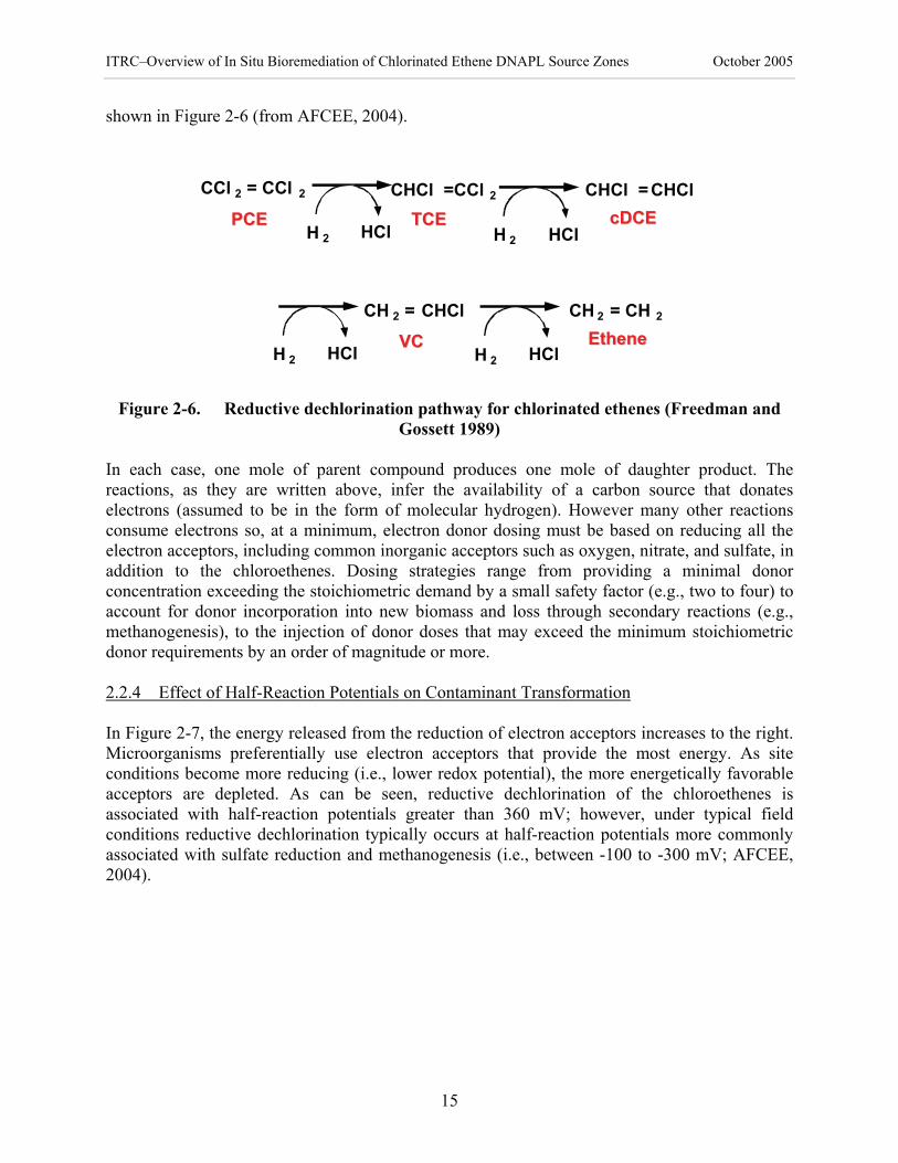
ITRC–Overview of In Situ Bioremediation of Chlorinated Ethene DNAPL Source Zones October 2005
15
shown in Figure 2-6 (from AFCEE, 2004).
CCl 2 = CCl 2 CHCl =CCl 2
CH 2 = CHCl
CHCl =CHCl
CH 2 = CH 2
PCEPCE TCETCE cDCEcDCE
VCVC EtheneEthene
H 2 HCl H 2 HCl
H 2 HCl H 2 HCl
Figure 2-6. Reductive dechlorination pathway for chlorinated ethenes (Freedman and
Gossett 1989) In each case, one mole of parent compound produces one mole of daughter product. The reactions, as they are written above, infer the availability of a carbon source that donates electrons (assumed to be in the form of molecular hydrogen). However many other reactions consume electrons so, at a minimum, electron donor dosing must be based on reducing all the electron acceptors, including common inorganic acceptors such as oxygen, nitrate, and sulfate, in addition to the chloroethenes. Dosing strategies range from providing a minimal donor concentration exceeding the stoichiometric demand by a small safety factor (e.g., two to four) to account for donor incorporation into new biomass and loss through secondary reactions (e.g., methanogenesis), to the injection of donor doses that may exceed the minimum stoichiometric donor requirements by an order of magnitude or more. 2.2.4 Effect of Half-Reaction Potentials on Contaminant Transformation In Figure 2-7, the energy released from the reduction of electron acceptors increases to the right. Microorganisms preferentially use electron acceptors that provide the most energy. As site conditions become more reducing (i.e., lower redox potential), the more energetically favorable acceptors are depleted. As can be seen, reductive dechlorination of the chloroethenes is associated with half-reaction potentials greater than 360 mV; however, under typical field conditions reductive dechlorination typically occurs at half-reaction potentials more commonly associated with sulfate reduction and methanogenesis (i.e., between -100 to -300 mV; AFCEE, 2004).

ITRC–Overview of In Situ Bioremediation of Chlorinated Ethene DNAPL Source Zones October 2005
16
[Bases of arrows align with the potentials of the half reactions shown in volts. (Modified from Cookson, Jr. 1995)]
Figure 2-7. Half-reaction potentials of environmentally relevant redox reactions 2.2.5 pH Considerations The pH is a measure of the acid/base characteristic of water; specifically, it measures the hydrogen ion concentration present in water. The pH of most groundwater is in the neutral range between 6 and 8 (lower pH is acidic and higher pH is basic). Within this normal pH range, bacteria seem to function well. Recent field tests demonstrated that even with groundwater pH as low as 4, bacteria can be revived by raising the pH to 6-8 (Hatzinger 2003). With an increase in electron donors, an increase in microbiological metabolism will occur resulting in an increase in production of hydrogen ions, thus potentially decreasing the pH. Most groundwater media have a capacity to buffer pH. However, if during site characterization it is determined that the media have insufficient buffering capacity, then a pH-buffering chemical may need to be added to maintain pH in the optimum range for reductive dechlorination. Effects of pH may occur unexpectedly. The addition of large amounts of fermentable substrate, such as molasses, has been observed to cause dramatic decreases in pH, likely caused by the expected formation of organic acids, such as acetic acid, exceeding the site buffering capacity. Prior to treatment, this possibility may be assessed by measuring the buffering capacity of the site soil and studying the types of site-specific microcosms present. 2.3 Site Issues Affecting Applicability and Feasibility of ISB Application Many issues need to be considered when evaluating ISB as a primary or secondary treatment.
Reductions(electron acceptors)
SO4 = to HS-
Fe++ to Fe(OH)3
CO2 to CH4H+ to H2
H2 to H+
EDB to EHCA to PCE
O2 to H2ONO3
- to N2
CT to CFPCE to TCE
CF to MC
TCA to 1,1-DCATCE to DCE
1,1-DCA to CANO3
- to NO2-
DCE to VC
0 +50 +100-50
0 +0.5 +1.0-0.5
0 +5 +15-5 +10pE'
E°' (V)
Free Energy (kJ/mol of electrons transferred
NADH to NAD+
Vitamin B-12 (reduced to oxidized)Acetate to CO2
Oxidations (electron donors) Hydrogenolysis
favorable
Dichloro-elimination
favorable
Reductions(electron acceptors)
SO4 = to HS-
Fe++ to Fe(OH)3
CO2 to CH4H+ to H2
H2 to H+
EDB to EHCA to PCE
O2 to H2ONO3
- to N2
CT to CFPCE to TCE
CF to MC
TCA to 1,1-DCATCE to DCE
1,1-DCA to CANO3
- to NO2-
DCE to VC
0 +50 +100-50
0 +0.5 +1.0-0.5
0 +5 +15-5 +10pE'
E°' (V)
Free Energy (kJ/mol of electrons transferred
NADH to NAD+
Vitamin B-12 (reduced to oxidized)Acetate to CO2
Oxidations (electron donors)
Oxidations (electron donors) Hydrogenolysis
favorable
Dichloro-elimination
favorable

ITRC–Overview of In Situ Bioremediation of Chlorinated Ethene DNAPL Source Zones October 2005
17
During the site characterization phase, a sufficiently detailed understanding of critical factors, such as the microbiology, chemistry, and hydrogeology of the site, must be obtained to properly apply ISB as a remediation strategy. Following adequate site characterization and development of an SCM, the next step is to identify the biogeochemistry (redox conditions) present in the subsurface and establish whether the primary ISB pathway for chlorinated ethenes (reductive dechlorination) can proceed. Since reductive dechlorination is the primary pathway, reducing conditions are required. This typically occurs when an electron donor (carbon source) is present to reduce the ORP to the desired level. Many options for electron donor exist, and selection should be based on site-specific considerations. ISB-8 Sections 4.4.4 and 9.4.3.2 provide further discussion of laboratory treatability tests and their importance (ITRC 2000b). Other site issues to consider when determining the feasibility of ISB application include the DNAPL architecture at the site (i.e., whether the DNAPL is present in pools or as residual), the potential for biofouling, and the adequacy of mixing of any added amendment. These considerations are described in detail below. 2.3.1 DNAPL Architecture DNAPL architecture is critical to ISB efficacy. Bioremediation does not make sense for sites where the DNAPL is largely located in pools. It makes much more sense for sites dominated by ganglia (residual phase) DNAPL because the surface to volume ratio is much larger, leading to much greater potential for dissolution and biodegradation at and near the nonaqueous phase liquid (NAPL)-water interfaces. Modeling evidence by Christ et al. (2003) shows that the ganglia-to-pool ratio is important to the potential efficacy of bioremediation alone or bioremediaiton following surfactant-enhanced extraction. This point is discussed further in Section 3.5, but the important conclusion is that bioremediation will be far more effective at sites where most of the DNAPL occurs as ganglia. 2.3.2 Biofouling As described in ISB-8 (ITRC 2002), biofouling
is attributed to the increase in microbial populations and perhaps more importantly, to the creation by cells of extra cellular polysaccharides. These slimy polysaccharides are important for the accumulation of microorganisms on surfaces or within porous media and can contribute significantly to biofouling of a formation or injection well. A portion of amendment goes to the creation of new bacteria (biomass). Eventually, continued unchecked bacterial growth is likely to reduce circulation and injection of the amendment, and may lead to a plugged formation or injection well (i.e., biofouling)…Various operating strategies have been devised to minimize this potentially undesirable outcome. These methods are not formalized, but rather various engineering approaches have been used over the years. No one approach is a clear winner. However, it is an issue that must be considered in system design and operation.
ISB-8 Section 4.4.7 includes a more complete discussion of options to reduce biofouling. Biofouling increases substantially under aerobic conditions, and therefore it is important to
ITRC–Overview of In Situ Bioremediation of Chlorinated Ethene DNAPL Source Zones October 2005
18
maintain anaerobic conditions to minimize biofouling problems. Certain techniques (i.e., use of hydrogen peroxide) to decrease biofouling may increase aerobic conditions and should be managed appropriately to ensure anaerobic conditions are maintained. 2.3.3 Mixing As noted in ISB-8 (ITRC 2002), ISB systems require the presence of contaminant-degrading bacteria, plus appropriate concentrations of electron acceptors, electron donors, and microbial nutrients. If a required component is absent, the biodegradation process slows and even stops. Consequently, the focus of a successful remediation system is to design an effective delivery process that will produce adequate amendment mixing in the subsurface treatment area (see ISB-8 Section 4.4.8 for further discussion). Widespread presence of DNAPLs in low permeability media poses significant challenges for assessment of their behavior and implementation of effective remediation technologies (Siegrist and Slack 2000). Most remedial methods that involve fluid flow perform poorly in low permeability media. In fractures or tight formations, amendment mixing can be a problem. The two major issues regarding geologic fractures and tight formations are the difficulty of locating and delineating these features and the problem of providing adequate distribution of a particular ISB amendment into the targeted geological environment. Formations containing clay, silt, and rock impede mass transfer rates and thus limit the desired effect of the ISB amendment. While geologic fractures represent “open” channels for the movement of fluids, these fractures can also cause inadequate distribution of ISB amendment within the entire subsurface environment. Hydraulic and pneumatic fracturing are two technologies that can enhance the remediation of subsurface contaminants. Fracturing is the injection of either air or another gas into a tight geologic formation at sufficient pressure to create artificial small fractures. These fractures increase permeability and provide an enhanced, homogeneous environment for remediation treatment. Hydraulic fracturing can improve the performance of other remediation methods, such as oxidation, reductive dechlorination, and bioaugmentation, by enhancing delivery of reactive agents to the subsurface. 3. TECHNICAL CONSIDERATIONS FOR ISB OF CHLORINATED ETHENE
DNAPL SOURCE ZONES As noted in Section 1.1, the potential for biodegradation of chlorinated organic solvents has been recognized since the early 1980’s. Both co-metabolic and anaerobic biodegradation pathways have been known for almost two decades (Vogel et al. 1987). Anaerobic biodegradation in particular has been used commercially for natural and enhanced remediation of dissolved phase plumes (AFCEE 2004, USEPA 1998). The documents referenced in this overview provide excellent background on the use of ISB for dissolved plumes and include in-depth discussions of the microbiology, biochemistry, and engineering considerations involved in ISB for chlorinated ethenes; however, these documents do not address source zone treatment. The discussion in this section provides background information on ISB and, in particular, focuses on source zone issues related to ISB of chlorinated ethene DNAPLs.

ITRC–Overview of In Situ Bioremediation of Chlorinated Ethene DNAPL Source Zones October 2005
19
Discussed in the following sections are issues related to: definition and location of DNAPL source areas (Section 3.1); functional site remediation objectives that may be applied to ISB application for chlorinated ethene DNAPL source zones (Section 3.2); geochemical and biological mechanisms used by ISB for removal of chlorinated ethene DNAPL contamination (Section 3.3); geochemical and biological environmental requirements for successful application of ISB (Section 3.4); and design implications based on modeling ISB of source zones (Section 3.5). The key points made in this section are as follows: • Since delineation of DNAPL source zones is difficult, remediation technologies that can
cost-effectively treat a zone of the aquifer without exact delineation (such as ISB) are preferred for these sites.
• Several mechanisms, including biological and abiotic, contribute to enhanced mass removal during ISB of DNAPL source areas.
• ISB promises to cost-effectively shorten remediation time frames for DNAPL source areas comprised primarily of residual or sorbed mass, but probably will not affect the time frame for sites with significant drainable DNAPL mass.
3.1 Identifying DNAPL Source Zones Treating a DNAPL source zone effectively requires that the source zone be indentified. The National Research Council panel on Source Zone Remediation defined a source zone as a subsurface zone “that acts as a reservoir that sustains a contaminant plume in groundwater, surface water, or air, or acts as a source for direct exposure. This volume is or has been in contact with separate phase contaminant (NAPL or solid)” (NRC, 2005). The typical rule of thumb for identifying a DNAPL source area is the observation of DNAPL-forming compounds at more than 1% of their aqueous-phase solubility. However, such rules of thumb should not be rigidly applied for reasons discussed elsewhere (ITRC 2003a). Finding the location of a DNAPL source area is challenging because of the non-uniform and unpredictable behavior of DNAPL in the subsurface. The pattern of DNAPL movement is highly site dependent and is influenced by soil lithology, pore size distribution, and structure. Due to these difficulties in exactly locating DNAPL contamination, the presence of DNAPL and especially residual DNAPL is usually inferred by high dissolved-phase concentrations. If DNAPL is present, its location is typically known at best only within a few meters to tens of meters. Thus, treatment methods that can remediate DNAPL on a broad scale without requiring the exact location of the DNAPL are desirable. Not all significant subsurface sources of chlorinated ethene contamination will appear the same. The formation of a separate-phase liquid in a monitoring well, for instance, is evidence of the presence of drainable NAPL which may be most effectively treated through direct extraction. Similarly, substantial nonaqueous-phase mass may be present in a sorbed phase without generating an aqueous-phase concentration indicative of DNAPL. Large sorbed-phase sources may also serve as long-term sources of aquifer contamination, and the challenges in locating and treating these materials in aquifers are similar to those associated with DNAPLs.

ITRC–Overview of In Situ Bioremediation of Chlorinated Ethene DNAPL Source Zones October 2005
20
3.2 Functional Site Remediation Objectives for ISB Application ISB of DNAPLs was not considered feasible until the 1990s, primarily because the chlorinated ethene concentrations within source areas were considered potentially toxic (Pankow and Cherry 1996). Since that time, however, the use of ISB has increased based on three separate lines of evidence that point to the viability of ISB for source areas. First, multiple, comprehensive studies clearly identified the limitations of active pump-and-treat remediation programs. Second, as highly aggressive treatment technologies, such as in situ thermal treatment or in situ chemical oxidation, were applied to source zones, it was noted that large contaminant mass removals attributed to these aggressive technologies would not necessarily result in large decreases in subsurface contaminant concentrations and compliance with regulatory criteria. Third, emerging laboratory and field evidence demonstrated that dechlorinating organisms can tolerate very high chlorinated ethene concentrations and can potentially enhance the rate of DNAPL dissolution. (USEPA 1989, Doty and Travis 1991, USEPA 1992, Bartow and Davenport 1992, NRC 1994, USEPA 1996, USEPA 1999). While all three of these lines of evidence were important, the experience with pump-and-treat programs was pivotal in that it drew a sharp distinction between source removal and plume containment. This distinction forced industry and the regulatory community to reexamine the definition of remediation success. As studies indicated that rates of pump-and-treat contaminant mass removal gradually declined over time, they also demonstrated that plume concentrations would rebound following shut-down of the pump-and-treat systems. Therefore, it became evident that these systems might require indefinite operation and that their primary value was in containing the spread of contamination within their capture zone. The principal lesson for remediation stakeholders from this experience was the critical need to unambiguously define the objectives of site remediation (USEPA 1996, NRC 2004). While it is clear that the absolute objective of remediation should be the protection of human health and the environment, there is substantial uncertainty in the means to achieve this result. Accordingly, given the difficulty of developing quantitative, well-defined metrics for this objective (ITRC 2004, NRC 2004), a range of functional site remediation objectives are commonly used. Some possible objectives for remediation of a DNAPL-contaminated site, listed here and discussed in more detail in Section 5.1, are as follows: • removal of contaminant mass • reduction of contaminant mass flux/concentration • reduction of contaminant plume life • reduction of project life-cycle cost The critical issue in selecting ISB is determining whether it can be effective at meeting or helping to meet the defined site remediation objectives within the time frame desired. While the overall effectiveness of ISB for chlorinated ethene DNAPL source zone applications is still relatively poorly understood, emerging evidence from a limited number of laboratory and field studies indicate that ISB has the potential to address many DNAPL sites. For instance, a recent Navy survey indicates an increase in the use of ISB for DNAPLs at sites where some sort of

ITRC–Overview of In Situ Bioremediation of Chlorinated Ethene DNAPL Source Zones October 2005
21
source zone treatment has been attempted. The survey found that ISB had been used at 20% of the sites, only slightly less than the number of sites at which in situ thermal treatment and chemical oxidation were applied (GeoSyntec 2004). ISB may also be less costly than other treatment alternatives. A recent survey of field-scale source zone treatment projects conducted by Groundwater Services, Inc., found that the reported average costs for the three dominant technologies were $61/yd3 for thermal treatment, $26/yd3 for in situ chemical oxidation, and $16/yd3 for ISB (McDade et al. 2005). Please note that these costs are taken from a single published survey and are provided for information only, not as an endorsement of their validity. 3.3 Geochemical and Biological Mechanisms of ISB for Removal of Chlorinated Ethene
DNAPL Sources As discussed in Section 1, enhanced ISB in the context of this document is the introduction of an electron donor and possibly nonindigenous microbes to enhance the removal of DNAPLs and the sorbed phase mass through reductive dechlorination. Enhanced removal may be accomplished by inducing a steep concentration gradient between the DNAPL and dissolved phases, but a separate phase donor such as vegetable oil may also be added to sequester the DNAPL in situ and foster biodegradation of DNAPL constituents as they solubilize over time. Note that bioremediation does not work directly on the free-phase DNAPL. Instead, the technology reduces contaminants through degradation and solubilization processes that occur near the water-DNAPL interface. The contaminant mass stored in the nonaqueous phase must transfer into the aqueous phase before it can be subjected to the dechlorination processes. This nonaqueous phase dominates the contaminant mass in sites where DNAPL is present and, in many cases, where there is a sorbed-phase mass component (see Section 2.1.3). As described in Section 2, enhanced reductive dechlorination occurs through addition of an organic electron donor to facilitate the sequential transformation of chlorinated ethenes as follows:
PCE → TCE → cis-DCE → VC → ethene The partitioning coefficients (Koc) of degradation products decrease with each step in the transformation, thus each degradation product will be less sorptive than the previous degradation product (see Table 2-1 for contaminant specific Koc values). In addition, aqueous solubility increases from PCE to TCE to DCE. Using these properties, the mechanisms that are currently understood to enhance DNAPL mass removal during bioremediation of DNAPL source zones can be divided into the three types briefly described below (Sorenson 2002). 3.3.1 Increased Concentration Gradient The first and most widely described mechanism discussed in the literature is enhancement of the mass transfer rate during ISB resulting from an increase in concentration gradient due to contaminant degradation in the aqueous phase (Seagren et al.1993, Seagren et al. 1994; Carr et al. 2000, Cope and Hughes 2001; Yang and McCarty 2000, 2002). The initial prediction of this

ITRC–Overview of In Situ Bioremediation of Chlorinated Ethene DNAPL Source Zones October 2005
22
effect was based solely on modeling and is discussed further in Section 3.5. of Carr et al. (2000). Cope and Hughes (2001) and Carr et al. (2000) demonstrated this effect using columns and batch reactors, respectively. In the columns, PCE removal from a NAPL in biotic systems was 6.3 times greater than that observed in an abiotic “washout.” This result was similar to the observation of about a 3-fold increase in PCE removal rates from a NAPL in the continuous-flow stirred-tank reactor. The total chlorinated ethene removal rate was 5 to 6 times greater for some of the biotic columns compared to the abiotic. Similarly, Yang and McCarty (2000, 2002) found that biological dechlorination activity increased aqueous phase total chlorinated ethene concentrations by about a factor of 5 compared to abiotic controls with PCE DNAPL. This work showed that dechlorinating organisms can withstand concentrations of total chlorinated ethenes in solution that exceed saturation concentrations of PCE on a molar basis. In fact, the high concentrations very near DNAPL inhibited the activity of other organisms, such as methanogens, that could potentially compete with dechlorinators for hydrogen, leading to speculation that the high concentrations might increase the efficiency of the bioremediation process.
3.3.2 Increased Solubility of Degradation Products The second mechanism is enhanced mass transfer into the aqueous phase due to the changes in properties of the degradation products relative to the parent compounds. Specifically, the increased solubility of degradation products (especially DCE) has been indicated as affecting enhanced mass transfer by facilitating more total moles of contaminant in solution than would be possible for the parent compounds alone. Carr et al. (2000) found that the enhanced mass removal in the batch reactors discussed above could be modeled using this mechanism and the first. The decreased Koc values of the degradation products have also been implicated because of the decrease in sorbed mass relative to the parent compounds. This “enhanced desorption” effect is inferred based on the contaminant properties, but it has not been well documented or quantified to date. 3.3.3 Abiotic Electron Donor Interactions The third mechanism proposed is abiotic interaction of electron donor solutions with the contaminant mass. The impact of surfactants and cosolvents on chlorinated ethene NAPL dissolution has been known for several years (Deitsch and Smith 1995, ITRC 2003b DNAPLs-3) and is the basis of several enhanced flushing technologies (e.g., AATDF 1998, Jawitz et al. 2000). However, the impact of solubilization by an electron donor solution has only recently been investigated. When high concentrations of soluble substrate are injected into CVOC source areas, some increase in the effective solubility of the contaminant may occur. Sorenson (2002) and Payne et al. (2001) report apparent increased dissolution of CVOCs from source areas when organic substrates were injected to stimulate anaerobic biodegradation, which is partially attributed to increases in CVOC solubility or perhaps increased desorption. It has been proposed that the observed enhanced mass transfer through either dissolution or desorption might be related to measured decreases in interfacial tension at high electron donor concentrations (e.g., 30% sodium lactate), or surfactant/cosolvent effects resulting from electron donor fermentation into alcohols, ketones, rhamnolipids, and other solubilizing agents. Although there is indirect evidence for this third mechanism (Sorenson, 2002, ARCADIS 2002, Bury and Miller 1993), its quantitative impact and practical importance under field conditions remain controversial.

ITRC–Overview of In Situ Bioremediation of Chlorinated Ethene DNAPL Source Zones October 2005
23
The complete dissolution of nonaqueous phase contaminant mass is limited by several factors, including the typically large amount of nonaqueous phase mass present, as compared to the aqueous phase, and the slow rate of dissolution. At some sites, significant destruction of contaminant mass in the source area can be achieved by increasing the rate of contaminant dissolution. However, even with dissolution rate increases, source areas at other sites are expected to persist for many decades, due to the large amount of nonaqueous phase mass present. Despite variation in source area characteristics, enhancing the contaminant dissolution rate remains a key process objective for bioremediation of source areas. 3.4 Geochemical and Biological Environmental Requirements for ISB Application Although the activities of numerous organisms are required for successful anaerobic biodegradation, the key process is the stepwise reductive dechlorination of PCE ultimately to ethene (Section 2.2.3). The basic geochemical and biological requirements for successful ISB of chlorinated ethene DNAPL source zones are apparent from a consideration of the background material described in Section 2.2. Appropriate redox conditions for complete reductive dechlorination and a capable microbial community, as introduced in Section 2, are two requirements for facilitating complete reductive dechlorination. A sufficient electron donor distribution to stimulate biological activity is another requirement that can be manipulated. These three requirements are discussed below. 3.4.1 Electron Donor Distribution Without an electron donor, reductive dechlorination cannot occur. Therefore, distributing an appropriate electron donor, often a fermentable carbon source, is key for successful ISB of chlorinated ethenes. An electron donor is needed not only for reduction of the contaminants, but also for reduction of competing electron acceptors (see Section 2.2). The electron donor addition strategy depends in part on the concentrations of competing electron acceptors, but probably depends more on the contaminant mass in the target treatment zone. In high concentration chlorinated ethene source zones, relatively high concentrations of electron donor are generally required to achieve adequate mass removal rates. Achieving sufficient electron donor distribution can be challenging at low permeability sites. Generally, two strategies have been used for introducing an electron donor to a site. The first strategy is a more passive approach in which a long-lasting solid or semi-solid electron donor, such as HRC-X™ or vegetable oil, is added directly to the DNAPL source area, generally through multiple Geoprobe points. This approach is relatively slow, and it relies almost entirely on the biological mechanisms for contaminant mass transfer and destruction. The second strategy is a more active approach based on more frequent injections of aqueous electron donors, such as lactate or molasses, in some cases with recirculation of the donor solution through the target zone. In this approach, the donor can be more thoroughly distributed throughout the subsurface and in addition to the biological mechanisms for removing DNAPL mass, the donor itself or its metabolites may directly solubilize DNAPL, presumably through cosolvent and surfactant properties. The longevity of the donor used can also affect the distribution. Various donors can persist in the subsurface for periods ranging from a few weeks to several years (see AFCEE,

ITRC–Overview of In Situ Bioremediation of Chlorinated Ethene DNAPL Source Zones October 2005
24
2004), and this longevity can impact how far downgradient the donor may be transported. 3.4.2 Redox Conditions Redox conditions are closely related to the electron donor distribution. When electron donor distribution is insufficient, conditions often will not be sufficiently reducing to achieve complete dechlorination, causing the process to stall at DCE. Wood and Sorenson (2004) provided several case study examples of incomplete dechlorination resulting from inadequate electron donor distribution. Incomplete dechlorination can often be overcome through improved distribution, which in some cases simply means introducing higher electron donor concentrations, or in other cases, more frequent injections. As alluded to in Section 2.2, the dominant microbial community in a groundwater system is largely dependent upon the distribution of electron acceptors. While PCE and TCE reduction might occur under iron-reducing conditions, reduction of DCE and VC to ethene generally requires at least sulfate reducing conditions, or preferably, methanogenic conditions (McCarty 1997, Freedman and Gossett 1989). There is some debate regarding the theoretical performance of dechlorination reactions under methanogenic conditions. Thermodynamic calculations and laboratory studies have been cited to suggest that methanogens should out-compete dechlorinators in the presence of high electron donor concentrations, implying that redox conditions should not be fully methanogenic (e.g., Smatlak et al. 1996, Fennell and Gossett 1998). These studies have generally been performed at temperatures that are elevated relative to groundwater, and have used reactant concentrations that are more typical of laboratory than field conditions. However, longer-term laboratory and field studies suggest that the competition between dechlorinators and methanogens is not a significant factor (e.g., Fennell and Gossett 1998). In fact, under field conditions, methanogenic activity appears to have little detrimental impact on dechlorination activity, perhaps because the predominant methanogens are those that use acetate instead of the hydrogenotrophic methanogens that would compete with dechlorinators (Macbeth et al. 2004). 3.4.3 Microbial Community While it is widely accepted that bacteria capable of anaerobic reductive dechlorination are vital to biological dehalogenation processes in anoxic environments (Smidt et al. 2000), recent advances in molecular techniques now allow scientists to characterize microbial communities, including dechlorinators, more fully. These advances have led to the discovery of many organisms capable of dechlorinating various compounds (Holliger et al. 1999). Many bacteria are capable of reducing PCE and TCE to DCE (McCarty 1997), but only Dehalococcoides spp. have been found to be capable of complete dechlorination of PCE and TCE to ethene in a pure culture (e.g., Maymo-Gatell et al. 1997). In fact, an increasing body of evidence suggests that complete biological reductive dechlorination of PCE and TCE to ethene requires certain strains of the bacteria Dehalococcoides spp. (Loffler et al. 2003). Multiple Dehalococcoides organisms, including strains KB-1/VC (Duhamel et al. 2004), BAV1 (He et al. 2003), and VS (Cupples et al. 2003), mediate dechlorination of cis-DCE and VC to ethene.

ITRC–Overview of In Situ Bioremediation of Chlorinated Ethene DNAPL Source Zones October 2005
25
Of particular importance is a recent study of 24 field sites in North America and Europe (Hendricksen et al. 2002). This study found that strains of Dehalococcoides were present at all 21 sites that exhibited complete dechlorination to ethene. None of these organisms were found at the three sites examined where dechlorination stopped at cis-DCE. This fact suggests that, while Dehalococcoides spp. are relatively common and widely distributed, their absence at a site might prevent complete dechlorination. Site data have not been published to date to refute the importance of Dehalococcoides spp. for complete biological reductive dechlorination. However, the inability to detect them at a site does not necessarily mean that complete dechlorination will not occur. Their numbers may be very low at some sites and their distribution sufficiently patchy that detection can be very difficult. Environmental conditions may change and Dehalococcoides spp. may become established at a later time, given the appropriate conditions. Moreover, other factors may complete the dechlorination process, including co-metabolic destruction of DCE or VC by other organisms, abiotic reactions that destroy incomplete dechlorination products, or dechlorination by some yet-to-be-discovered organism or process. In addition, it should be noted that the detection of the Dehalococcoides genus does not guarantee that complete dechlorination of PCE or TCE will occur at a site. Some strains of the Dehalococcoides genus are not capable of dechlorinating PCE and TCE, though they may degrade other chlorinated contaminants (e.g., Bunge et al. 2003). Due to the apparent stalling of reductive dechlorination at intermediate degradation products such as cis-DCE at some sites, many argue that selected mixed or pure cultures should be added to sites to facilitate complete dechlorination of chlorinated ethenes. Although Dehalococcoides spp. are found at many sites, they are not ubiquitous (Hendricksen et al. 2002). Further, their numbers are often low and their growth rates in situ may be very slow, leading to long acclimation times. Therefore, researchers have begun to test several mixed cultures containing Dehalococcoides spp. for use in bioaugmentation. Initial results have been promising (e.g., Ellis et al. 2000, Major et al. 2002), and the demonstrated success at some sites has led to the introduction of several commercially available cultures. 3.5 Modeling of Bioremediation Removal Mechanisms for Chlorinated Ethene DNAPL
Sources The first publications suggesting that bioremediation could be useful for source zone treatment focused on mechanism type 1 (described in Section 3.3), the potential to enhance dissolution of DNAPL (actually NAPL in general) within a source area by increasing the concentration gradients (Seagren et al. 1993, Seagren et al. 1994). These modeling studies showed that biodegradation near a source can enhance mass transfer rates by decreasing the aqueous concentrations near the interface, thereby significantly accelerating mass transfer from a NAPL to the aqueous phase and subsequent mass removal. The degree to which mass transfer was enhanced was determined to be a function of the relative rates of advection and biodegradation. As noted in Section 3.3, Carr et al. (2000) were among the first to document enhanced dissolution of NAPL due to biodegradation experimentally. They also developed an analytical model that adequately reproduced the experimental results based on mechanism types 1 and 2 (described in Section 3.3). Seagren et al. (2002) performed column studies to evaluate their

ITRC–Overview of In Situ Bioremediation of Chlorinated Ethene DNAPL Source Zones October 2005
26
earlier theoretical predictions of enhanced mass transfer, and observed up to a two-fold increase in dissolution rates. However, they were evaluating toluene as a NAPL and it was speculated that the toxicity of high toluene concentrations might have limited the dissolution enhancement due to biodegradation. Chu et al. (2003) developed a two-dimensional advection-dispersion model for enhanced dissolution of PCE from a pool due to biodegradation. Interestingly, they demonstrated that enhanced dissolution increased with electron donor concentration because the model predicted that unlimited electron donor allowed bacteria to grow closest to the DNAPL-water interface, thereby maximizing the concentration gradient. It was also noted that bioclogging of pore spaces could also impact long-term effects. Recently, Christ et al. (2005) investigated a theoretical combination of aggressive mass removal via surfactant flooding with bioremediation through numerical modeling. Based on the literature reviewed in this document, the authors assumed bioremediation enhanced dissolution rates by a factor of 5 compared to natural gradient dissolution. A key parameter in the cleanup timeframe was found to be the “ganglia-to-pool ratio” (G:P ratio), which describes the amount of DNAPL mass in the residual phase compared to the amount in the drainable free phase. Simulations with low G:P ratios had the longest remediation timeframes, while those with high ratios had the shortest timeframes. This result reiterates the fact that bioremediation is probably not well-suited for sites with a large amount of drainable (pooled) DNAPL. Not surprisingly, given the model assumptions, bioremediation alone was projected to shorten remediation timeframes by about a factor of 5 relative to natural gradient dissolution. When combined with aggressive mass removal through surfactant flushing, remediation timeframes were projected to be reduced by one to two orders of magnitude. Finally, it should be noted that Groundwater Services, Inc. has recently developed screening tools for DNAPL remediation timeframe estimation for the ESTCP and the AFCEE (see the Source DK Model website at http://www.gsi-net.com/Software/SourceDK.htm). These tools are used to estimate dissolved phase concentrations downgradient from a DNAPL source and to estimate the longevity of that source under various scenarios, including flushing (pump and treat), active treatment, and natural biodegradation. Preliminary results suggest that enhanced biodegradation might shorten DNAPL remediation timeframes considerably as compared to natural gradient dissolution, though the magnitude of the decreases is estimated to be less than that predicted by Christ et al. (2005). 4. THE STATE OF ISB TECHNOLOGY APPLICATIONS This section discusses the current state of ISB technology applications for chlorinated ethene DNAPL source zones. An overview is provided on ISB strategies for designing and applying an ISB treatment system for either mass removal of chlorinated ethene DNAPLs or for source containment (Section 4.1). The requirements for successful implementation of ISB as a primary mode of treatment for chlorinated ethene DNAPL sources are briefly described (Section 4.2). Several laboratory and field examples are presented regarding different ISB applications and how they relate to site-specific characteristics (Sections 4.2.1 and 4.2.2). Injection strategies for ISB applications under different site conditions (Sections 4.2.3 and 4.2.4), and bioaugmentation for ISB of chlorinated ethene DNAPLs (Section 4.3) are discussed. Applications of ISB as a

ITRC–Overview of In Situ Bioremediation of Chlorinated Ethene DNAPL Source Zones October 2005
27
secondary treatment in combination with other treatment alternatives are also provided (Section 4.4). Finally, the strengths and limitations of applying ISB for chlorinated ethene DNAPL sources are discussed (Section 4.5). The key points made in this section are as follows: • ISB is a flexible technology that can have different functional objectives and can be
implemented in a wide variety of ways, as a sole treatment technology or as part of a treatment train.
• ISB can be used to enhance mass removal from a source area, to contain the source area, or both, and it can be implemented using active systems that often employ recirculation or passive approaches relying more on natural hydraulic gradients.
• Bioaugmentation is a viable approach for achieving complete dechlorination at sites that do not have a capable indigenous microbial community.
• ISB’s strengths for source treatment include its flexibility, its compatibility with other technologies, its low cost relative to other technologies, its relative ease of implementation, and the lack of process wastes generated during treatment.
• ISB’s limitations include that it is relatively slow, it is generally not suitable for sources with drainable DNAPL, it may be inhibited by other contaminants, it can impact secondary water quality parameters, and it is still not well-understood or widely accepted for source treatment.
4.1 ISB Strategy Overview As discussed in Section 3.2, the design of a bioremediation system for DNAPLs may have several goals. Most commonly, ISB is deployed to enhance the rate of removal of chlorinated ethene compounds, and thereby decrease the plume longevity and/or source loading to the dissolved plume after treatment. However, ISB may also be used to provide biological containment of the source, thereby, cutting off or reducing the plume loading. Finally, ISB may be used to sequester the source and potentially degrade contaminants in place, effectively a combination of the first two objectives. The appropriate metrics and criteria for stopping active treatment must be chosen with these goals clearly defined and agreed-upon. ISB may be applied as a primary or secondary treatment technology. In either case, there are two general strategies based on electron donor type that have been used, and the responsible parties need to make a conscious choice between these strategies. The first strategy is more passive in that a long-lasting solid, semi-solid, or nonaqueous electron donor (e.g., chitin, HRC, or vegetable oil) is added directly to the source area, generally through multiple direct-push injection points. This approach is slower because of the passive electron donor distribution and relies almost entirely on the biological enhancement mechanisms for mass removal (i.e., depleting the aqueous phase and conversion to less-chlorinated metabolites that partition into water more readily). The second strategy is a more aggressive, active approach based on frequent injections of aqueous donors, like lactate or molasses. In this approach, the donor can be more thoroughly distributed throughout the target zone, and the donor itself or its metabolites can directly enhance mass removal by solubilizing or desorbing DNAPL, as well as enhancing biodegradation.

ITRC–Overview of In Situ Bioremediation of Chlorinated Ethene DNAPL Source Zones October 2005
28
When bioremediation is used as a secondary treatment, it may be coupled with any of several other more aggressive technologies. For example, thermal treatment may be used for hot spots or for a limited time, and bioremediation can be used for less contaminated areas or as a polishing step. Similar uses in conjunction with chemical oxidation and surfactant or cosolvent flushing have also been demonstrated. In these cases, it is important to plan ahead to take advantage of positive synergies, such as the use of cosolvents as an electron donor or the positive impacts of higher temperature on biological degradation rates, and avoid potential negative effects, such as temporary sterilization by heating. The optimum approach to implementing bioremediation for DNAPLs is not yet known, and site-specific factors are critical in designing and operating a source zone bioremediation system. The choice of electron donor will depend on a variety of site-specific environmental factors, as well as the specific remedial objectives. The method for delivery of electron donors needs to be carefully designed, as this is often the limiting factor in the success of in situ remediation, and ongoing operational monitoring can be crucial. 4.2 ISB as the Primary Mode of Chlorinated Ethene DNAPL Source Treatment There are two basic approaches to ISB as a mode of treatment: • groundwater recirculating systems that extract, amend, and re-inject groundwater to establish
a dechlorination zone in the aquifer • systems that rely on periodic injections of electron donor (can be slow-release or aqueous)
and distribution by natural groundwater flows Figure 4-1 shows the layout for published examples of each type of system. The left side of the figure represents the extraction/injection recirculation strategy deployed at the Brooks Air Force Base bioaugmentation study, reported by Major et al. (2002). The system on the right side of the figure represents the distribution of injected carbon using existing natural gradient groundwater flow patterns, as implemented at the Midwestern U.S. full-scale biostimulation site, reported by Payne et al. (2001). Each system achieved complete dechlorination of chlorinated ethenes in less than 12 months. The recirculation system exchanged groundwater in the treated volume approximately once every seven days. The natural gradient system received electron donor injections on a monthly basis, and the injected electron donor was consumed in the first 100 days of groundwater travel (approximately 100 feet downgradient from the injection wells). The treatment cost for the natural gradient system closely matched the ISB estimate of $16/yd3 (reported by McDade et al. 2005 and cited previously in Section 3.2).

ITRC–Overview of In Situ Bioremediation of Chlorinated Ethene DNAPL Source Zones October 2005
29
Key: EW = extraction well; IW = injection well; MW = monitoring well Figure 4-1. Examples of carbon loading strategies for enhanced reductive dechlorination
of PCE and TCE (to-scale) As noted in Section 4.1, ISB technology can be considered for two primary strategies at DNAPL-contaminated sites. The first strategy is to use ISB for mass removal in the DNAPL source zone. The second strategy is to use ISB for containment of the DNAPL source zone. Once the remediation objectives have been defined (as introduced in Section 3.2 and discussed in detail in Section 5.1), the effects of site-specific considerations on the application of ISB must be considered. Table 4-1 illustrates the impact of some important site-specific characteristics on the effectiveness of the ISB application for mass removal and source containment for DNAPL sites. One of the key differences between the applications that is revealed in the table is that source containment using ISB is probably applicable at a wider variety of sites than is mass removal. This is as true for ISB as it is for many other technologies because many site-specific characteristics that can make mass removal very difficult (e.g., low permeability, mass diffused in secondary porosity, and complex DNAPL architecture) are less problematic for containment.
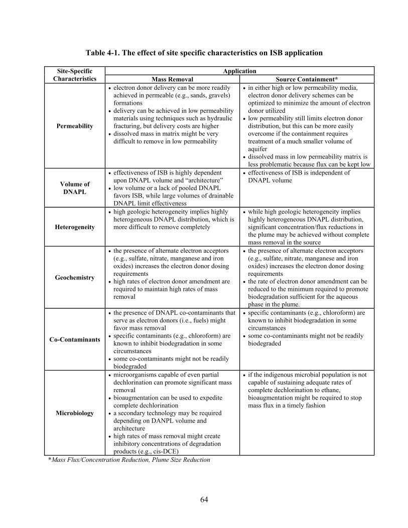
64
Table 4-1. The effect of site specific characteristics on ISB application
Application Site-Specific Characteristics Mass Removal Source Containment*
Permeability
• electron donor delivery can be more readily achieved in permeable (e.g., sands, gravels) formations
• delivery can be achieved in low permeability materials using techniques such as hydraulic fracturing, but delivery costs are higher
• dissolved mass in matrix might be very difficult to remove in low permeability
• in either high or low permeability media, electron donor delivery schemes can be optimized to minimize the amount of electron donor utilized
• low permeability still limits electron donor distribution, but this can be more easily overcome if the containment requires treatment of a much smaller volume of aquifer
• dissolved mass in low permeability matrix is less problematic because flux can be kept low
Volume of DNAPL
• effectiveness of ISB is highly dependent upon DNAPL volume and “architecture”
• low volume or a lack of pooled DNAPL favors ISB, while large volumes of drainable DNAPL limit effectiveness
• effectiveness of ISB is independent of DNAPL volume
Heterogeneity
• high geologic heterogeneity implies highly heterogeneous DNAPL distribution, which is more difficult to remove completely
• while high geologic heterogeneity implies highly heterogeneous DNAPL distribution, significant concentration/flux reductions in the plume may be achieved without complete mass removal in the source
Geochemistry
• the presence of alternate electron acceptors (e.g., sulfate, nitrate, manganese and iron oxides) increases the electron donor dosing requirements
• high rates of electron donor amendment are required to maintain high rates of mass removal
• the presence of alternate electron acceptors (e.g., sulfate, nitrate, manganese and iron oxides) increases the electron donor dosing requirements
• the rate of electron donor amendment can be reduced to the minimum required to promote biodegradation sufficient for the aqueous phase in the plume.
Co-Contaminants
• the presence of DNAPL co-contaminants that serve as electron donors (i.e., fuels) might favor mass removal
• specific contaminants (e.g., chloroform) are known to inhibit biodegradation in some circumstances
• some co-contaminants might not be readily biodegraded
• specific contaminants (e.g., chloroform) are known to inhibit biodegradation in some circumstances
• some co-contaminants might not be readily biodegraded
Microbiology
• microorganisms capable of even partial dechlorination can promote significant mass removal
• bioaugmentation can be used to expedite complete dechlorination
• a secondary technology may be required depending on DANPL volume and architecture
• high rates of mass removal might create inhibitory concentrations of degradation products (e.g., cis-DCE)
• if the indigenous microbial population is not capable of sustaining adequate rates of complete dechlorination to ethane, bioaugmentation might be required to stop mass flux in a timely fashion
*Mass Flux/Concentration Reduction, Plume Size Reduction

ITRC–Overview of In Situ Bioremediation of Chlorinated Ethene DNAPL Source Zones October 2005
31
4.2.1 ISB for Mass Removal Chlorinated solvent contamination is often associated with a DNAPL source area that continuously supplies chlorinated compounds to the dissolved phase. Elimination or reduction of these source areas can result in swifter contaminant plume remediation and a quicker path to site closure. Engineered bioremediation is one approach that can be used to effectively treat a large-scale zone of aquifer. With a properly designed amendment delivery system, any of the substrates can be used to completely surround the discontinuously-located DNAPL mass. Traditional schools of thought held that bioremediation in high concentration zones typical of source areas would be infeasible because of two reasons. First, it was thought that contaminants would be toxic to the microorganisms of interest. Second, it was thought that the impact on nonaqueous sources would be no more effective using ISB than using pump-and-treat remediation. However, recent research in both laboratory and field settings has shown that enhanced bioremediation can be extremely effective for chlorinated ethene source areas, and that dechlorinators actually may have an ecological niche in high concentration source areas. The mechanisms currently identified for enhanced mass removal in chlorinated ethene DNAPL source zones during ISB were discussed in Section 3. Several laboratory and modeling studies were briefly described, along with some field examples. In this section, empirical results from the laboratory and the field are provided in more detail to provide more insight into potential applications and as illustrations of what might be expected of the technology. 4.2.1.1 Laboratory Studies As mentioned in Section 3, Carr et al. (2000) conducted a laboratory study on the influence of dechlorinating microorganisms and their degradation products in the presence of a PCE DNAPL. The study was conducted in biotic and abiotic continuous-flow stir-tank reactors. Results showed that dechlorination resulted in a significant increase in the PCE removal rates from the NAPL. The authors noted that “the combined effects of dissolution and dechlorination on the removal of chlorinated ethenes from the NAPL were described using a mathematical model that approximated dechlorination as a pseudo-first-order process. It was determined that total chlorinated ethenes removal from the NAPL would be achieved in 13 days in biotic reactors, as compared to 77 days in the abiotic reactors, corresponding to an 83% reduction in longevity of the chlorinated ethenes component of the NAPL.” In a similar study, Yang and McCarty (2000) evaluated the possibility of biological reductive dechlorination of high concentrations of PCE. Their study showed that a bacterial culture was able to transform PCE at saturated conditions and that an increase in PCE DNAPL dissolution of up to 5-fold occurred under biologically reducing conditions. In a follow-up study concerning biologically induced dissolution of PCE DNAPL conducted by Yang and McCarty (2002), the substrate (electron donor) selection was deemed important for reductive dechlorination. This study evaluated pentanol, calcium oleate, and olive oil for bioenhanced DNAPL dissolution. Results from the study showed all substrates increased DNAPL dissolution, and methanogenesis was extensive in the pentanol and oleate study columns. The study suggested that methanogens can efficiently use the electron donor, and may produce considerable biomass that has the

ITRC–Overview of In Situ Bioremediation of Chlorinated Ethene DNAPL Source Zones October 2005
32
potential to clog flow paths. However, the presence of high PCE concentrations near DNAPL accumulations can be toxic to methanogens. “Substrate near PCE ganglia would be used primarily by dehalogenators because of PCE toxicity there, but methanogens could use the oleate that was not near DNAPL” (Yang and McCarty 2002). Another study, conducted by Cope and Hughes (2001), used upflow glass bead-filled columns to study the influence of dechlorinating microorganisms on PCE and its reduction products in a residual NAPL source zone. Their results showed that dechlorination resulted in an increase in total PCE removal by a factor of up to 16 greater than ambient dissolution. Reductive dechlorination degradation products were observed, and total chlorinated ethene removal was enhanced from 5.0 to 6.5 times greater than the removal that would have resulted from dissolution alone. 4.2.1.2 Field Studies ISB has also been successfully demonstrated under field conditions, at both pilot- and full-scale implementations. Several of the more controlled and well-monitored field studies are briefly described below. In general, the results demonstrate that complete dechlorination can occur in a source zone, enhanced mass removal can occur as a result of ISB within the source, and the enhancement factor as compared to dissolution only is significant, though more modest than that suggested by the laboratory studies described above. One of the higher-visibility full-scale applications of ISB has been at the Idaho National Engineering and Environmental Laboratory (INEEL) Test Area North (TAN), where TCE, PCE and 1,2-DCE were detected in drinking water supply wells above risk based concentrations. The groundwater contaminant plume was about two miles long, at a depth of 200–450 feet, and concentrations of TCE in groundwater ranged from historical highs of over 300 mg/L in the source zone (approximately 100-foot radius) to 5 μg/L at the distal end of the plume. Enhanced reductive dechlorination was used in the source zone, and food-grade sodium lactate with potable water was injected into the aquifer. Periodic lactate injections accelerated the dechlorination in the source zone, degrading contaminants in the aqueous phase near the source and accelerating degradation of the source material itself (separate-phase DNAPL), as evidenced by large (near 20-fold) but temporary increases in aqueous TCE concentrations (Sorenson 2002). A reduction of TCE to non-detectable levels has been shown in a number of wells, including the original injection (disposal) well and the three monitoring wells where TCE concentrations had been the highest. Continued groundwater monitoring has shown no rebound while the system continues to operate. Analysis of stable carbon isotopes in the TCE showed that the signature of the TCE changed, suggesting that the process directly impacted the source material (Song et al. 2002, USDOE 2002). Another field study of ISB was conducted at Naval Weapons Station Seal Beach in California. This study demonstrated enhanced mass transfer using ISB in a source zone, apparently comprised primarily of sorbed PCE mass (French et al. 2003). Although the highest concentrations in the plume, located in a shallow coastal aquifer, were only on the order of one to a few mg/L, they persisted in one area for several years. Sodium lactate was injected into the area as a 3% solution periodically over several months. Enhanced mass transfer caused PCE

ITRC–Overview of In Situ Bioremediation of Chlorinated Ethene DNAPL Source Zones October 2005
33
concentrations to increase by 2.5- to over 10-fold in monitoring wells near the injection well, and stoichiometric conversion to DCE was observed in all of them. The site was later bioaugmented successfully to achieve complete dechlorination of the contaminants (French et al. 2004). At Dover Air Force Base in Delaware, historic spills of chlorinated solvents contaminated ground water with TCE, cis-1,2 DCE, and PCE with average concentrations of 4800 μg/L, 1200 μg/L, and 3 μg/L, respectively. An accelerated ISB demonstration system was installed that included the extraction of contaminated water and additions of nutrients, substrate, and microorganisms prior to reinjection. The system showed complete in situ degradation of chlorinated organic solvents to ethane, using groundwater recirculation and amendment through augmentation of the native microbial community with a culture from Largo, Florida (Ellis et al. 2000). A more recent demonstration has been conducted at Dover AFB to more thoroughly investigate the potential for ISB to enhance DNAPL dissolution rates in source zones. In this pilot test, PCE was added to enclosed test cells, and electron donor (lactic acid) was added after an initial baseline equilibration phase. The test cells were then bioaugmented (with the KB-1™ culture) The phases include a groundwater flush to determine baseline dissolution, biostimulation to determine the impact of nutrient addition, and bioaugmentation to determine the impact of the addition of PCE degrading microorganisms. The results to date demonstrate that ISB can increase mass removal, by a factor of approximately 2, and that bioaugmentation was necessary to promote complete dechlorination of the PCE to ethene. Again, stable carbon isotope analysis has been valuable in demonstrating biological degradation has occurred, and microbial analyses have shown that significant levels of dechlorinating organisms (over 107 cells per L) have been maintained within the source area for over a year. At the Kennedy Space Center, groundwater amended with ethanol was recirculated through a test plot constructed within a TCE DNAPL source area (Battelle, 2004). Prior to ethanol amendment, groundwater concentrations of TCE as high as the solubility were initially observed in some locations. The TCE concentration in the recirculated groundwater was 160 mg/L. The addition of ethanol at a concentration equivalent to a 4-fold stoichiometric excess to that required to reduce all electron acceptor in groundwater (primarily TCE and sulfate), resulted in an increase in TCE biodegradation and significant accumulation of 1,2-cis-DCE and VC. Electron donor addition and groundwater recirculation continued for 107 days. Subsequently, the test plot was bioaugmented with 40 L of KB-1™, a commercially-available dechlorinating microbial consortium (Duhamel et al. 2002). After bioaugmentation, ethene was the dominant degradation product and concentrations as high as 96 mg/L were observed. An increase in total chloroethene concentrations following bioaugmentation suggested that there was an increase in the rate of TCE mass removal from the test plot. The examples discussed for using ISB for mass removal are all similar in the context of the remediation objectives in Sections 3.2 and 5.1. They all showed good results in terms of mass removal, reduction in local aqueous concentrations, and reduction in toxicity. None of them were operated in such a way as to demonstrate a decrease in mass flux. Conditions at all of the field sites were somewhat favorable for ISB. In terms of Tables 4-1 and 5-1, all of the examples had moderate to high permeability and low DNAPL volumes. The heterogeneity was variable for the

ITRC–Overview of In Situ Bioremediation of Chlorinated Ethene DNAPL Source Zones October 2005
34
field sites, with two being relatively homogeneous, while the INEEL TAN site is quite heterogeneous, but highly transmissive. Alternate electron acceptors were not prohibitively high at any of the sites, although sulfate was as high as 500 mg/L at Naval Weapons Station Seal Beach. Bioaugmentation was performed at two of the field sites to facilitate complete reductive dechlorination. 4.2.2 ISB for Source Containment As shown in Table 4-1, some site conditions make mass removal using ISB very difficult, but are more tractable when containment is the primary goal. Besides demonstrating enhanced mass removal, the examples discussed in Section 4.2.1 demonstrate that complete dechlorination can be stimulated. The use of ISB for source containment is defined as stimulating a biological treatment zone within or immediately downgradient of the DNAPL source zone to stop or minimize the flux of contaminants leaving the source zone. Containment is most typically achieved by establishing a reactive barrier downgradient of the source, through injection of an electron donor into wells or injection points along a transect perpendicular to the groundwater flow path (see Figure 4-2). Alternatively, physical barriers may be established, with biological treatment in defined areas (so-called funnel-and-gate applications). Finally, electron donors, such as vegetable oil, may be injected into and near the source area to sequester the DNAPL and degrade DNAPL constituents as they solubilize. In any application, achieving containment requires facilitating complete reductive dechlorination of contaminants in the aqueous phase.

ITRC–Overview of In Situ Bioremediation of Chlorinated Ethene DNAPL Source Zones October 2005
35
Figure 4-2. Schematic for ISB applications for source containment Source containment is applicable at a wider variety of sites than is mass removal because all of the conditions that made the sites in the previous examples good candidates for using ISB for mass removal in the source zone do not necessarily have to be met to use ISB for containment. For example, low permeability might preclude ISB from being used for mass removal in a spatially large source zone because the cost of closely spaced wells is too high. It might be possible, however, to achieve containment with just a fraction of the wells required for enhancing mass transfer, thereby making containment feasible. As another example, contacting the DNAPL source mass is not important for containment because containment can occur downgradient, so DNAPL architecture may be much less important for containment than for mass removal. Another characteristic that might make containment more widely applicable than mass removal is that injection strategies that could be appropriate for containment, such as trenching, might not be appropriate for mass removal (see Section 4.2.4). 4.2.3 Electron Donor Injection Strategies Several different techniques are available to inject electron donors into groundwater, and the appropriate technique depends not only on the strategic objectives, but also on the electron

ITRC–Overview of In Situ Bioremediation of Chlorinated Ethene DNAPL Source Zones October 2005
36
donor. The most common strategy is to inundate the source zone with electron donor to make the entire source zone sufficiently anaerobic for complete dechlorination and to distribute donor throughout the source zone. Less commonly, donor is distributed in a barrier along the downgradient edge of the source zone. In either case, the donor can be distributed in relatively passive or active delivery modes. The most common approach used is a relatively passive delivery, involving direct injection of the electron donor throughout the contaminated zone. The donor addition may include some dispersive mixing, such as pressure pulsing or water chases, but for the most part practitioners rely on ambient groundwater flow to distribute the electron donor throughout the subsurface. In this approach, groundwater monitoring is used to judge the need for further electron donor injections. This approach is used almost exclusively when adding insoluble or semi-soluble donors, such as chitin, vegetable oil, or HRCTM, and is often used with soluble donors as well. Often, this approach is associated with the addition of an excess concentration of electron donor. There are relatively low ongoing costs associated with passive electron donor delivery. An active electron donor delivery approach is one that uses continuous recirculation of electron donor-amended groundwater through the contaminated zone. Active delivery may be employed to provide electron donor throughout the source zone or within a barrier configuration. While there is an ongoing cost associated with operation of the recirculation system, this approach provides better mixing of the electron donor and the groundwater, and can provide some ability to optimize electron donor dosing based on monitoring data. Between these two approaches, there are a number of semi-passive electron donor injection strategies that try to balance the cost of additional injection locations against the operating costs of groundwater recirculation. 4.2.4 Electron Donor Injection Techniques Different techniques are available to inject electron donors into groundwater, and the appropriate technique depends not only on the relevant application (mass removal or plume containment) but also on the electron donor selected. The following sections describe five different techniques for distributing electron donors. A brief description of each is provided, along with the strengths and weaknesses in terms of the site-specific characteristics in Table 4-1. None of the injection techniques provide unique advantages for the last two characteristics in the table, so these are not discussed. 4.2.4.1 Semi-passive, large injection point spacing This technique relies on pulsed injection of significant volumes of electron donor solution to achieve a large radius of influence around a single injection point. Examples of this include the INEEL TAN site, where a radius of influence of approximately 100 feet from a single injection well was achieved (Martin and Sorenson 2004), and the California Seal Beach site, where a radius of influence of over 20 feet was achieved (French et al. 2003). This approach works best under moderate to high permeability conditions. It can be highly effective for enhancing mass transfer because of the volumes of high-concentration electron donor provided. It can work in heterogeneous systems, although the electron donor will follow the advective flow paths. The high volumes of electron donor solution are also well suited for removal of competing electron

ITRC–Overview of In Situ Bioremediation of Chlorinated Ethene DNAPL Source Zones October 2005
37
acceptors. 4.2.4.2 Passive, small injection point spacing This technique relies on either single injections or very infrequent injections of electron donor in closely spaced injection points on a grid that covers the DNAPL source zone. This approach is also effective at moderate to reasonably high permeability sites, although groundwater velocities that are very high can be problematic because little to no cross-gradient distribution of the electron donor occurs. It is also best in shallow sites where drilling costs are low, and it tends to be cost-prohibitive when direct-push techniques cannot be used. It can be somewhat effective for enhancing mass transfer, although concentrations that can be distributed away from the injection points tend to be lower than some other methods. Highly heterogeneous sites are problematic for this approach because the electron donor is not widely distributed from individual injection points. Relatively homogeneous sites with low to medium advection to dispersion ratios are best. Subject to the distribution limitations mentioned, concentrations of electron donor can generally be high enough to handle competing electron acceptors, except when acceptor concentrations are very high, as can be true for sulfate at some sites. 4.2.4.3 Forced advection This technique uses continuous pumping and re-injection to control groundwater flow and electron donor distribution. This approach provides the greatest engineering control, and it has been used to distribute electron donor and bacteria successfully in several published bioaugmentation demonstrations for treatment zones on the scale of approximately 10–30 feet long (Ellis et al. 2000, Major et al. 2002, Lendvay et al. 2003). The strengths of this approach are essentially the same as for the semi-passive approach, except that forced advection is somewhat more robust for slightly lower permeability sites or more heterogeneous sites because of the control over hydraulic gradients that is afforded. The hydraulic control can also be an advantage in bio-barrier applications where it is desirable to maximize well spacing. 4.2.4.4 Trenching This technique involves the installation of electron donor into the subsurface in a trench. This approach has limited applicability for inundation of source areas because of the nearly two-dimensional nature of a trench. It is most typically used to install permeable reactive biobarriers (or “biowalls”), though one or a series of trenches may be used to treat a source in a relatively permeable medium with a high groundwater velocity. As with the passive electron donor addition, lower concentrations of electron donor are likely to migrate downgradient from the barrier. Heterogeneity is less problematic for a permeable reactive barrier than other techniques because it allows distribution across an entire cross-section of the source zone, regardless of the heterogeneity. 4.2.4.5 Hydraulic Fracturing This technique emplaces electron donor during hydraulic fracturing of the formation. It has been successfully applied for facilitating ISB of a source zone in a low permeability formation at the

ITRC–Overview of In Situ Bioremediation of Chlorinated Ethene DNAPL Source Zones October 2005
38
Distler Brickyard Superfund Site (Martin et al. 2001, Bures et al. 2004a, 2004b). A radius of influence of approximately 15–20 feet was achieved for individual fractures at the site. This technique is probably best-suited to low permeability sites, although it can be used at higher-permeability sites as well. Mass transfer limitations are similar to the passive and trenching approaches, although the hydraulic fractures tend to cut across the heterogeneous units in a formation, helping to overcome some of the difficulties in distributing the donor effectively. 4.3 Bioaugmentation As noted in Section 3.4.3, an increasing body of evidence supports the notion that efficient, complete reductive dechlorination of chlorinated ethenes is best facilitated in the presence of Dehalococcoides spp. bacteria. At many sites, it might not be necessary to introduce these bacteria, but at several sites, the addition of an exogenous culture containing Dehalococcoides spp. has been shown to expedite cleanup. Several Dehalococcoides-containing bioaugmentation cultures have now been used in the field and are commercially available. Individual vendors often have specific protocols for implementing bioaugmentation, but the fundamental steps are essentially universal. 1. Preconditioning. The first step before injecting a Dehalococcoides-containing culture into site groundwater is to add sufficient quantities of donor to achieve anoxic conditions. This pre-conditioning will maximize the potential for survival of the strictly anaerobic Dehalococcoides and will minimize the lag time before the onset of complete dechlorination.
2. Inoculation. Care should be taken during inoculation to prevent exposure of the culture to oxygen, either during the transfer or in the receiving groundwater. Best results have been obtained using enriched cultures containing approximately 107 to 109 Dehalococcoides cells per milliliter. There are several studies in which large volumes of far less concentrated inoculants have been used (typically groundwater containing an active dechlorinating microbial population at densities 10–1000 lower than those cited above). However, the most common practice is the use of highly-enriched cultures. 3. Distribution. Bacterial distribution is more complex than electron donor distribution, and there are many factors that affect bacterial transport in groundwater. Nevertheless, transport on a scale of several tens of feet has been demonstrated in the field at several sites (Ellis et al. 2000, Major et al. 2002, Lendvay et al. 2003). Forced advection has been used successfully at these sites, although a semi-passive system was used successfully at the California Seal Beach site (French et al. 2004). Given the necessary preconditioning and appropriate care during inoculation, evidence of complete dechlorination is generally fairly rapid. Detections of VC and ethene usually occur within weeks to at most a few months. Distribution of bacteria can take longer depending on the scale of transport. The extent to which Dehalococcoides is retarded relative to groundwater velocity appears to vary significantly in the demonstrations published to date. In all cases, transport distances of tens of feet have been achieved in a few months. Some limitations for bioaugmentation to expedite ISB in DNAPL source zones might exist. For

ITRC–Overview of In Situ Bioremediation of Chlorinated Ethene DNAPL Source Zones October 2005
39
example, some strains of Dehalococcoides are inhibited by common co-contaminants, notably 1,1,1-trichloroethane (1,1,1-TCA), and research in this area is ongoing. Another example is that Dehalococcoides activity in some studies appears to be inhibited to some extent when DCE concentrations are extremely high, which can occur due to enhanced dissolution and biodegradation in DNAPL source zones. This is also an area of active research. These issues should be noted when considering bioaugmentation to ensure that expectations are realistic. 4.4 Using ISB in Combination with Other Treatment Technologies When bioremediation is used as a secondary treatment, it may be coupled with any of several other more aggressive technologies. For example, thermal treatment may be used for hot spots or for a limited time, and bioremediation can be used for less contaminated areas or as a polishing step. Similar uses in conjunction with chemical oxidation and surfactant or cosolvent flushing have also been demonstrated. In these cases, it is important to plan ahead to take advantage of positive synergies, such as the use of cosolvents as an electron donor or the positive impacts of higher temperature on biological degradation rates. It is also important to avoid potentially negative effects, such as temporary sterilization or unfavorable geochemical changes resulting from other treatment technologies. Despite anecdotal evidence that bioremediation has been employed as a secondary or polishing treatment technology, there has been limited research to date examining the performance of coupled bioremediation approaches. However, there are reasonable grounds for considering this approach and ongoing research is likely to increase its relevance. The following sections describe some of the possible coupled approaches, with examples of past applications. 4.4.1 ISB and Thermal Technologies Thermal technologies, including steam injection and electrical heating, work by volatilizing and mobilizing contaminants. Volatile components enter the vapor phase and migrate away from the injection wells toward cooler regions. Condensation occurs at the thermal front, creating a bank of contaminant in front of the advancing steam. DNAPL mobilization may also occur as a result of the decreased interfacial tension and lowered viscosity accompanying the increase in temperature (National Academy of Sciences 1999). Although only limited data are available, thermal technologies have several potential impacts on ISB. The high temperatures involved can reduce the population of viable microorganisms, with unforeseen results on the microbial community and reductive dechlorination. The residual heat is likely to increase the rate of biochemical reactions in the treated zone. Further, heating may result in geochemical changes. In each of these areas, only limited information is available on the potential relevance of these impacts to ISB. In a recent study at a polyaromatic hydrocarbon NAPL source zone, the effects of steam injection on soil microbial activity, community structure, and the potential for biodegradation of contaminants following steam treatment were evaluated (Richardson et al. 2002). Findings showed that samples collected while the subsurface was still hot were below detectable limits for microbial activity. However, soils that were slowly cooled showed microbial activity comparable to initial conditions. The study also showed that organisms capable of biodegradation were

ITRC–Overview of In Situ Bioremediation of Chlorinated Ethene DNAPL Source Zones October 2005
40
among the mesophilic populations that survived steam treatment. Similarly, in an EPA groundwater issues paper, Davis (1998) indicated that increased biological activity occurred at a steam injection site at Naval Air Station Lamoore, where in situ temperatures were as high as 100°C. A pilot study of six-phase heating (SPH) was conducted as part of a multiple technology demonstration for the in situ remediation of TCE present as DNAPL at Cape Canaveral in Florida. Average soil temperatures in the heated area ranged between 80°C and 120°C. The duration of the heating lasted 11 months, from August 18, 1999, to July 12, 2000. Soil sample analysis suggested that a rise in microbial activity after heating was responsible for biodegradation observed following the thermal study (Dettmer 2002). Subsequent laboratory experiments performed by Pacific Northwest National Laboratories (PNNL) confirmed the ability of indigenous microbial populations to degrade TCE at elevated temperatures (i.e., 70°C) and under anaerobic conditions similar to those during SPH operations. Further microbial analyses of samples from the SPH demonstration at Cape Canaveral suggested that thermal treatment reduced the numbers and diversity of the indigenous bacterial populations, but that the reduction was temporary (Battelle, 2001). A pilot field demonstration study conducted at West Quartermaster’s Fueling System in Operable Unit 5 at Fort Wainwright, Alaska, used radio-frequency heating (RFH) and SPH. Subsurface temperatures were elevated sequentially to above 30°C. Laboratory studies showed that the optimum temperature for microbial consortia existing in the soil was about 20°C, and biodegradation rates declined at temperatures above 30°C. Respiration tests were performed at the unheated control site, the RFH site, and the SPH site. Results showed a varying increase in biodegradation rates for the RFH and SPH sites heated to 10°C to 25°C. Interpretation of these results showed that biodegradation rates increased with an increase in soil temperature above 5°C, up to about 30°C (Dettmer 2002). There has also been some recent microcosm evidence that temperature increases comparable to those observed during thermal treatment (e.g., 100° C for 10 days) inhibit the activity of both hydrocarbon-degrading and dechlorinating organisms (Friis et al. 2004). Further, temperature increases appear to increase the solubility of natural organic carbon present in the soil, which appears to be readily utilized as an electron donor by survivor organisms to create reducing conditions. However, it is clear that further research is needed to determine the effects of thermal treatments on geochemistry, redox conditions, and biodegradation capacity. In general, it appears the dechlorinating activity may be temporarily inhibited by the high temperature associated with thermal treatment although this activity appears to recover. In reviewing the available data on thermal treatment impacts on bioremediation, Dettmer (2002) concluded that
bioremediation can be implemented as a polishing technique. It is apparent that bioremediation has potential to follow thermal treatment, and that thermal treatment may even enhance the biodegradation rates of contaminants. The combination of thermal treatment for source removal and bioremediation for dissolved phase reduction could significantly reduce remediation costs and energy consumption at a contaminated site.

ITRC–Overview of In Situ Bioremediation of Chlorinated Ethene DNAPL Source Zones October 2005
41
[However], [l]ittle is known about the thermal effects on dechlorinating microorganisms. Dechlorinating microorganisms are typically known to be mesophilic and non-spore forming, which means they do not possess the capability to survive high temperatures. No research was found, however, on the possible existence of thermophilic dechlorinating bacteria. Clearly, more research on the effects of elevated temperatures on dechlorinating bacteria is needed. The combination of thermal treatment for source removal and bioremediation as a polishing technique has potential to be used as an effective treatment train in the near future. Before this combination can be implemented, however, a better knowledge of the degradation processes affected by thermal activity must be acquired.
4.4.2 ISB and Electrokinetic Bioremediation Electrokinetic bioremediation (bioelectric remediation) technology for continuous in situ treatment of groundwater or soil uses electro-osmosis or electrochemical migration to initiate or enhance ISB (GWRTC 1997). In theory, it may provide improved amendment distribution in the DNAPL source zones for increased biodissolution and biodegradation. Electro-osmosis applies a direct current to the subsurface to accelerate groundwater flow. This process is applied to ISB to increase amendment mixing and may be most applicable in low permeability areas. Electrochemical migration occurs when an electrical field is applied primarily to fine silty clays and mixed clays and moves uniformly through the fine soils. It helps ions more readily move through small pore spaces. This electrical field may disperse some simple organic ISB amendments more uniformly through the contaminant zone. In 1995, an industrial consortium implemented an electrokinetics pilot demonstration treatment study at the DOE Paducah Gaseous Diffusion Plant through a treatment process termed Lasagna™ by Monsanto (DOE 1996). This process used electrokinetics to move contaminants in soil pore water into treatment zones where the contaminants could be captured or destroyed. The pilot study was conducted in a 15 by 10 by 15-foot volume where TCE maximum concentrations were at 1,760 ppm. DNAPL locations within the study cell were reduced to 1 ppm levels. The demonstration did not include testing of bioremediation potential following treatment. 4.4.3 ISB and Surfactant or Cosolvent Floods Surfactants and cosolvents are typically used to enhance the dissolution of DNAPL constituents into the aqueous phase, thereby increasing the rate of source mass removal. Common cosolvents include alcohols such as ethanol, ter-butanol, methanol, and isopropanol (ITRC 2003b). These technologies are particularly relevant to ISB in that most surfactants and cosolvents can act as electron donors and tend to promote the growth of indigenous microorganisms (including dechlorinators). Further, these technologies mobilize VOCs adsorbed to soil particles. Few studies have been completed to specifically examine the sequential application of these technologies with ISB. The most significant demonstration of the potential for combining enhanced flushing is a study completed at the Sages Dry Cleaning site in Jacksonville, Florida, where a cosolvent pilot-scale field demonstration was conducted in August, 1998. PCE DNAPL

ITRC–Overview of In Situ Bioremediation of Chlorinated Ethene DNAPL Source Zones October 2005
42
was recovered from an existing on-site water supply well and maximum concentrations of PCE, TCE, and cis-1,2-DCE in groundwater were 930 mg/l, 34 mg/l and 19 mg/l, respectively. The ethanol cosolvent consisted of 95% ethanol and 5% water. The residual ethanol then served as an electron donor for reductive dechlorination. PCE concentrations were reduced 60%, and increases in the concentration of PCE degradation products, the production of dissolved methane and hydrogen, and the depletion of sulfate indicated that the ethanol flush resulted in highly reducing conditions and increased the rate of reductive dechlorination. The Sages site results led researchers to conclude that “residual ethanol remaining after cosolvent flushing has significantly enhanced in situ biological dechlorination processes for natural attenuation of the contaminant mass” (ITRC 2003b). Results from this demonstration also strongly suggest that cosolvent flushing systems can be designed and used to aid in the enhancement of biodegradation processes at DNAPL sites (Mravik et al. 2003). 4.4.4 ISB and In Situ Chemical Oxidation One of the most widely applied source treatment technologies has been in situ chemical oxidation (ISCO). Although there has been considerable speculation about the potential impact of ISCO on bioremediation after treatment, research on the topic is still needed. Results from ongoing laboratory-scale research suggest that ISCO does not result in complete sterilization, and that dechlorinators can survive and remain active after ISCO treatment. In fact, ISCO may result in a flush of biodegradation following treatment, as a consequence of the chemical decomposition of more complex native organic matter. The existing data characterizing the impacts of oxidants of anaerobic bioremediation processes provide contradictory evidence for the feasibility of utilizing bioremediation following oxidation. In the case of permanganate, oxidation of constituents of the aquifer matrix can produce soluble products. For example, sulfide minerals may be oxidized to produce sulfate (Nelson et al. 2002), while some of the natural insoluble organic carbon content of the soil is partially oxidized to carboxylic acids and aldehydes (Hayes 1989). Increases in dissolved organic carbon concentrations observed at some field sites (Droste et al. 2002) may promote reducing conditions favoring reductive dechlorination. However, permanganate oxidation results in the deposition of manganese oxide (MnO2). Under anoxic conditions, manganese is essentially insoluble, but the anaerobic conditions typically associated with ISB of chlorinated ethenes also favor manganese reduction. As an oxidizing agent, contact with permanganate adversely impacts microorganisms present in groundwater, although complete sterilization of the microbial population is generally considered unlikely to occur. In a study evaluating the impact of permanganate addition on indigenous microorganisms, reductions in the populations of aerobic and anaerobic heterotrophs, nitrate-, nitrite-, and sulfate-reducers, and methanogens following treatment ranged from 47–99.95% (Klens et al. 2001). Replicate samples collected six months after treatment suggested that the population of heterotrophic aerobic microorganisms rebounded although enumeration of anaerobic heterotrophic microorganisms indicated that only minimal recovery of these microorganisms had occurred. While permanganate may result in large reductions in microbial populations, there is at least limited microcosm evidence to suggest that ISCO does not intrinsically inhibit the dechlorinating activity of the microbial population (Rowland et al. 2001).

ITRC–Overview of In Situ Bioremediation of Chlorinated Ethene DNAPL Source Zones October 2005
43
Achieving a transition to a microbial population dominated by dechlorinating microorganisms (e.g., Dehalococcoides) requires a significant shift in redox conditions. Since manganese-reducing organisms use hydrogen much more efficiently than dechlorinating organisms (AFCEE 2004), it may be the case that the establishment of dechlorinating populations may only be possible in anaerobic niches where manganese dioxide has been completely depleted (Crimi and Siegrist 2004). However, it has also been reported that TCE dechlorination at least to DCE might occur under manganese-reducing conditions (Hrapovic et al. 2005). A similar circumstance is expected to occur in the case of Fenton’s reagent, which results in the production of oxygen and significant increases in temperature. Oxygen gas, the ultimate product of hydrogen peroxide decomposition, can be trapped in the pore spaces and act as a long-term source of dissolved oxygen gas in groundwater. Application of the conventional Fenton’s reagent to a site resulted in highly acidic pH conditions and elevated concentrations of dissolved oxygen (up to 24 mg/L) in the treatment zone relative to a background location seventeen months after oxidant injection (Kastner et al. 1997, 2000). Dissolved oxygen is toxic to anaerobic microorganisms, including Dehalococcoides, and increases the amount of electron donor required to create reducing conditions suited to reductive dechlorination. 4.4.5 ISB and Nano-Scale Zero Valent Iron (ZVI) Improvements in the ability to produce ZVI at a controlled particle size gave rise to the idea of injecting nano-scale ZVI for treatment of chloroethene-contaminated groundwater (Elliot and Zhang 2001). When combined with an electron donor formulation (e.g., vegetable oil), ZVI can be incorporated into an amendment that offers the potential for rapid destruction of chloroethenes (dissolved phase and NAPL), along with the capability for prolonged biodegradation of residual contamination. Because ZVI is a reductant, there are obvious potential synergies between use of ZVI in combination with ISB (i.e., ZVI and ISB both operate under reducing conditions). Recently an amendment formulation was developed that combines vegetable oil and nano-scale ZVI (Geiger et al. 2003). This formulation, termed emulsified Zero-Valent Iron (EZVI), was first tested in the field at the NASA Launch Complex 34 site, for treatment of TCE-containing DNAPL (Quinn, et al. 2005). The emulsion droplets consist of an inner core of water and nano-scale ZVI that is contained within an oil/surfactant membrane. This oil/surfactant membrane provides protection of the ZVI particles and can cause the droplets to be attracted to deposits of chloroethene-containing NAPL. It may also be effective in combination with ISB because the oil and surfactant can serve as longer-term electron donors. At the Launch Complex 34 site, soil and groundwater samples were collected before and after the 5-day injection period to evaluate effectiveness. Within 90 days, decreases in soil concentrations of TCE were greater than 80% at four of the six sampling locations. TCE levels in groundwater were reduced from 57–100% at the depth intervals where EZVI was delivered. At the downgradient transect, the average reduction in TCE concentration was 68%, and the mass flux decreased by about 56% over a period of 6 months. Production of cis-DCE and VC was also observed, suggesting that biodegradation was an important contributor to the performance (Quinn, et al. 2005). Follow-on research with EZVI is being funded through ESTCP to document

ITRC–Overview of In Situ Bioremediation of Chlorinated Ethene DNAPL Source Zones October 2005
44
the cost and performance under field conditions. 4.5 Strengths and Limitations of ISB Application The research cited thus far has revealed some of the key issues that affect the applicability, selection, and design of source zone ISB systems. The strengths and limitations of ISB technology are summarized in Table 4-2.
Table 4-2. Strengths and limitations of ISB
Strengths Limitations ISB can reduce the total contaminant mass in the dissolved, sorbed, and nonaqueous phases typically without creating process waste requiring further treatment.
ISB treatment will be slow in highly contaminated source zones and may not be appropriate for areas with drainable DNAPL. In some cases, complete contaminant destruction is not achieved, leaving the risk of a residual toxic intermediate.
Under appropriate conditions, ISB can meet regulatory criteria for target contaminants in groundwater.
Some contaminants are resistant to biodegradation or may be toxic to the microorganisms, impeding or preventing the bioremediation process.
ISB may be used in both short- and long-term timeframes, either by itself or following a more aggressive source zone treatment technology.
Source zone ISB can cause significant changes in water quality. Uncontrolled proliferation of the microorganisms might reduce permeability.
At sites where significant dechlorination takes place under naturally occurring conditions, ISB is compatible with and can accelerate existing attenuation processes.
It might be difficult to adequately characterize sources and to deliver reagents to them, thereby preventing enhanced DNAPL removal rates from equaling those observed in the laboratory.
Implementation of electron donor addition and bioaugmentation appears to be relatively straightforward.
Performance assessment and engineering optimization of ISB technologies are not well understood.
ISB may be a cost-competitive containment technology. The use of low-cost electron donor amendment strategies, passive or semi-passive, is probably required for cost-effective containment.
ISB is almost always faster than baseline pump-and-treat remediation
The effectiveness of ISB will vary from site to site and be largely dependent upon the site geology and the distribution of DNAPL in the subsurface.
It has become clear that ISB may not be appropriate for all DNAPL sites, particularly those with large accumulations of free-phase NAPL. Borden (2003) used a simple mass transfer biodegradation model to determine that significant enhanced dissolution from pooled NAPL was not likely. He concluded that containment of a source zone by ISB was possible, but that “enhanced anaerobic bioremediation is not likely to be effective for rapid restoration of heavily contaminated source areas.” As discussed in Section 3.5, recent work by Christ et al. (2005) has indicated that ISB may be very effective in reducing plume longevity in source zones with high G:P ratios, especially following a primary treatment, such as surfactant flushing. However, in source zones dominated by pooled accumulations of DNAPL, ISB would have much less impact on the plume longevity because of the limited mass transfer that is possible from the DNAPL to water phases. It is important to note that these modeling efforts focused on “rapid restoration.” However, it has become clear that ISB may be cost-effective even when deployed over relatively long periods of

ITRC–Overview of In Situ Bioremediation of Chlorinated Ethene DNAPL Source Zones October 2005
45
time. Given sufficient time, bioremediation may well achieve results equivalent to more aggressive, but more expensive, technologies, particularly other mass transfer-limited technologies such as ISCO and surfactant flushing. Thus, bioremediation may be favored where limited capital is available for the initial phase of remedial action. However, bioremediation might be less desirable at sites where rapid treatment is preferred, such as sites undergoing property transfer. Another consideration when selecting or designing ISB for a specific site is that it is often very difficult to deliver the necessary reagents to the source zone. Rapid degradation near the water-DNAPL interface is a key to biological enhancement of the mass transfer of chlorinated ethenes to the aqueous phase. Therefore, finding and targeting the DNAPL areas are critical to the efficient and successful use of ISB. The ability to target DNAPLs has improved somewhat over time, though it remains a particularly challenging problem. Although not the focus of this technology overview, the development of improved source characterization tools, such as membrane interface probes and partitioning tracer tests (Meinardus et al. 2002, Jawitz et al. 2003), could prove significant in helping to make ISB even more effective. Addition of electron donors can also cause changes that need to be recognized and monitored. These include high biochemical oxygen demand or chemical oxygen demand in groundwater, increases in dissolved metal concentrations, lower pH near injection points, production of gases such as methane and hydrogen sulfide, increases in groundwater or in the vadose zone of carcinogenic byproducts such as VC, possible blockage of pore spaces in the subsurface, and possible increased mobility of DNAPL constituents in the subsurface. These changes can impact downgradient groundwater quality, but in general, the alterations should dissipate with time and distance and should not pose insurmountable problems. Moreover, any technology designed to enhance mass transfer of DNAPL also involves some risk that DNAPL accumulations will be mobilized and that they may migrate within the subsurface. For that reason, ISB will often be applied in conjunction with hydraulic control of some type to contain or recover the mobilized DNAPL and the expected flush of dissolved contaminants. Finally, application of ISB alone is unlikely to be sufficient to reach maximum contaminant levels (MCLs). ISB may be particularly limited in low-permeability or heterogeneous settings (National Research Council 2004). There are fundamental constraints in situ that limit the ability of microorganisms to access all of the residual DNAPL present, especially if a significant fraction of the DNAPL diffuses into a surrounding low-permeability matrix (Parker et al. 1994) or migrates into inaccessible areas. Other technologies depending on aqueous delivery of reagents have demonstrated similar limitations (Stroo et al. 2003). 5. DEFINING AND MEASURING SYSTEM PERFORMANCE OF ISB
APPLICATIONS FOR CHLORINATED ETHENE DNAPL SOURCES Identifying appropriate performance measures is an important aspect of determining the progress and success of ISB activities. This section briefly defines several functional remediation objectives for clean up of sites contaminated with chlorinated ethene DNAPLs and the potential

ITRC–Overview of In Situ Bioremediation of Chlorinated Ethene DNAPL Source Zones October 2005
46
for ISB to achieve those objectives under various geological site conditions and DNAPL source strengths (Section 5.1). The remainder of this section provides a conceptual look at how to define the success of ISB system performance (Section 5.2) and some suggestions for measuring the level of successful performance (Section 5.3). Key points made in this section include the following: • ISB will likely not achieve typical closure criteria, but can achieve functional remediation
objectives such as reducing mass flux from the source, site remediation timeframes, or life-cycle site management costs.
• ISB will be most effective in relatively permeable, homogeneous aquifers in which the DNAPL is distributed predominantly as “ganglia,” or residual, non-pooled accumulations.
• Measuring the progress or success of ISB is an important issue that should be carefully considered. Typical metrics important in evaluating ISB include molar mass balances of the chlorinated ethenes and their degradation byproducts.
5.1 Potential for ISB to Achieve Functional Site Remediation Objectives As discussed in Section 3.2, the absolute objective of site remediation should be the protection of human health and the environment. However, a range of functional site remediation objectives are commonly used at many chlorinated ethene DNAPL sites because there is substantial uncertainty about the means to achieve the absolute objective and because there is difficulty developing quantitative well-defined metrics for this absolute objective. Under most conditions, ISB of chlorinated ethene DNAPL sources is unlikely to meet clean closure criteria across an entire site. In fact, it is rare that any chlorinated ethene DNAPL source depletion technology will meet this rigorous standard. Therefore, it may be necessary to develop less restrictive site-specific, risk-based functional objectives for source depletion in the vast majority of cases (Kavanaugh et al. 2003, NRC 2005). Following is a discussion of several possible functional site remediation objectives that can be applied to ISB of chlorinated ethene DNAPL sources. 1. Mass Removal. The least restrictive functional objective is mass removal. This is probably the most common stated metric of source depletion, i.e., how much total mass has been removed or destroyed as a fraction of the estimated original mass. Although quantitative criteria are difficult to develop or measure, ISB has been estimated to remove greater than 90% of the original mass under favorable conditions (McDade et al. 2005, GeoSyntec 2004). In many cases, the goal is simply to remove mass to the extent practicable, although many would argue that the goal should be to remove sufficient DNAPL from the source zone to make a significant difference in the future site care requirements. 2. Mass Flux/Concentration Reduction. In many other cases, the objective is to reduce the contaminant concentrations in groundwater leaving the source area, or less commonly the mass flux or mass discharge from the plume. Because the relationship between mass reduction and mass flux or concentration is not necessarily strictly linear, the reduction can be more or less than the mass removal estimate suggests (Enfield et al. 2002, Sale and McWhorter 2001, Stroo et al. 2003). Typically, the reduction in concentration or flux (expressed as a fraction or percentage of the pre-treatment levels) will be less than the mass removal in homogeneous hydrogeologies

ITRC–Overview of In Situ Bioremediation of Chlorinated Ethene DNAPL Source Zones October 2005
47
and greater than the mass removal in more heterogeneous ones (Stroo et al. 2003, Wood et al. 2003). 3. Plume Life Reduction. Often, the stated or assumed goal of source depletion is to reduce the lifetime of the associated dissolved phase plume. It is often assumed that there will be some relatively simple relationship between plume duration and mass removal. However, it is clear that such a simple relationship is unlikely because concentrations tend to plateau following a first-order decay kinetic pattern in which the majority of the life of a plume will be characterized by relatively low source mass and relatively low dissolved phase concentrations (Newell and Adamson, in press). 4. Life-Cycle Cost Reduction. Finally, the objective may be to reduce the life-cycle costs for site management. This objective is also difficult to define or estimate, given the limited history of any aggressive chlorinated ethene source depletion efforts. Since plumes will continue to require some form of containment for long periods of time following most source depletion efforts and the long-term operations and maintenance costs for these containment technologies can represent a substantial fraction of the life-cycle costs, it may be very difficult to make significant reductions in these costs at most sites unless relatively low-cost source depletion technologies can be used. For example, implementing a source depletion technology that facilitates the use of MNA following source treatment and mitigates the need for a pump and treat system would substantially reduce life-cycle cost. ISB of chlorinated ethene source zones remains a developing technology, but there is sufficient experience to make some generalizations about its potential efficacy for meeting the previously discussed functional remediation objectives for different types of sites. Table 5-1 summarizes the current consensus of the authors regarding ISB potential for different hydrogeologic and source conditions, although exceptions to these generalizations undoubtedly exist. In preparing this summary, the NRC (2005) categorization of hydrogeologic settings has been used: • Type I sites are characterized as granular, with mild heterogeneity and moderate to high
permeability. • Type II sites are granular, with mild heterogeneity and low permeability. • Type III sites have granular structure, with moderate to high heterogeneity. • Type IV sites are fractured media with low matrix porosity. • Type V sites are fractured with high matrix porosity. These are idealized sites but, in general, the difficulty in addressing DNAPL sources within these settings increases from Type I through Type V because it is increasingly difficult to deliver remedial agents to the DNAPL.

ITRC–Overview of In Situ Bioremediation of Chlorinated Ethene DNAPL Source Zones October 2005
48
Table 5-1. The ability of ISB to meet remediation objectives*
For the purpose of evaluating ISB, it is necessary to further characterize sources as either low-strength or high-strength. Low-strength sources are characterized by primarily residual and discontinuous DNAPL distributions, or in the terminology of Christ et al. (2005), high “ganglia- to-pool ratios” (i.e., G:P ratios of 1.0 or greater). That is, over half of the total DNAPL present can be found in discontinuous ganglia or as material sorbed onto the aquifer particles. In contrast, high-strength sources have G:P ratios below 0.3. That is, over 70% of the total DNAPL mass is present as “pools” or accumulations of free product within the subsurface in which the DNAPL content exceeds residual saturation. In reality, most sources are more complex than this categorization suggests. In addition, it is technically difficult to determine the average source strength at most DNAPL sites. Nevertheless, this type of classification can be useful in evaluating the feasibility of ISB or other source depletion technologies.
* This table represents the current consensus view of the authors about ISB potential under different conditions, although exceptions to these generalizations undoubtedly exist.

ITRC–Overview of In Situ Bioremediation of Chlorinated Ethene DNAPL Source Zones October 2005
49
It should be remembered that most experience with ISB has been over relatively short time periods. This limited experience has two implications important to this analysis. First, it is difficult to predict the long-term impacts of treatment, particularly on plume longevity or life-cycle costs. Second, it is also difficult to predict the impacts of longer ISB treatment durations. Continuing ISB treatment for a period of several years may well produce greater decreases in mass and flux, even in difficult hydrogeologic environments or with high-strength sources, while remaining cost-competitive. There is considerable interest in the potential for longer-term ISB treatment, so this assessment must be viewed as the current consensus regarding a rapidly-developing technology. The current understanding of the technology’s potential is likely to change as practitioners gain further experience. 5.2 Defining and Measuring Success of ISB Application for Chlorinated Ethene DNAPL
Source Treatment The functional site remediation objectives often represent the scientific measure against which a treatment technology is judged to be successful. Conceptually, there are essentially two ends of the spectrum for measuring this success. The first end of the spectrum is to define success as a measurable reduction in the cost of due care for the DNAPL source. For example, the ISB treatment might result in partial source removal, thereby reducing mass transfer to the aquifer to a level that allows natural attenuation of the remaining mass. This end of the success spectrum is one that responsible parties can more easily support, and the question of whether it is achievable is not so controversial. The other end of the spectrum for measuring success is to remove enough of the DNAPL mass so that groundwater concentrations are compliant with applicable drinking water standards at all possible points of measurement. Measuring success in this way often generates a great deal of debate, especially because the likelihood of total elimination of a long-standing DNAPL source from an aquifer is very low. Meeting a functional site remediation objective or a series of functional objectives is, perhaps, the most intuitive way to judge remediation activities. It is important to note that EPA often views a site remediation strategy for complicated groundwater cleanups as a phased approach, which may include intermediate performance objectives to demonstrate progress toward achieving the final cleanup goals. EPA refers to these objectives as “intermediate” because actions taken to meet these objectives will typically occur after a facility achieves its short-term protection goals, but before it achieves all final cleanup goals. EPA encourages regulators and facilities to establish intermediate objectives when they can use such goals to demonstrate progress toward meeting the ultimate final cleanup goals (USEPA 2002, section 3.0). To determine whether ISB has resulted in significant chlorinated ethene DNAPL source zone treatment, at least two important measures can be considered: the contaminant molar balance and increasing molarities of total alkenes. These two measures of success are discussed in the following sections. 5.2.1 Contaminant Molar Balance The dechlorination reaction sequence provides one mole of dechlorinated product molecules for every mole of starting material. That is, if 1.0 mole of PCE is degraded and close to 1.0 mole of

ITRC–Overview of In Situ Bioremediation of Chlorinated Ethene DNAPL Source Zones October 2005
50
dechlorination products (TCE, DCE, VC, and/or ethene) is observed, it could be concluded that enhanced reductive dechlorination is the mechanism responsible for the decrease of PCE. Alternatively, if 1.0 mole of PCE is degraded and only 0.1 mole of dechlorination products is observed, it is more difficult to conclude that enhanced reductive dechlorination is the mechanism responsible for the decrease of PCE. It is possible that anaerobic oxidation or abiotic dechlorination reactions has caused the disappearance, but those mechanisms are not enhanced reductive dechlorination in the sense of this discussion. This document is not meant to address methods to design, control, or document those processes. Moreover, closing the mass balance to 1.0 or greater demonstrates that the displacement of aquifer water by injected fluids is not the cause of any observed contaminant decrease. 5.2.2 Increasing Molarities of Total Alkenes When enhanced reductive dechlorination and its related processes dechlorinate sorbed-phase mass of PCE or TCE, the total molarity of chlorinated ethenes may increase significantly. In other words, the sum in moles per liter of
PCE + TCE + cis-DCE + VC + ethene + ethane
may be larger than that which would have been estimated from the mass of the PCE or TCE found in the dissolved phase. This characteristic can only occur if sorbed or nonaqueous-phase mass is being dechlorinated. 5.3 Stakeholder Issues One measure of success for any site remediation project is how well the remediation satisfies the expectations of concerned stakeholders. As with any site remediation project, stakeholder concerns must be addressed to successfully implement ISB. Stakeholder input is critical and should be sought at the earliest opportunity for any site where ISB is being considered as a remediation strategy. To allow the public to ask appropriate questions about the efficacy of the various alternative remediation options and to provide useful input to the informed decisions about whether ISB is the most viable remediation option, information should be provided to help the public understand the various advantages and disadvantages of ISB, along with other proposed alternative treatment methods. Among other things, stakeholders should • understand the various assumptions which will be used in the groundwater model; • know if the ISB technology is to stand alone or if it is part of a treatment train to reach the
desired end; • have a visual idea of what the ISB technology will require logistically, such as drill rigs,
power supply, and the number of truck trips required to transport materials; • know the noise implications of the technology selected; • understand what the mass balance implications are for each technology selected, as well as
the potential consequences of daughter products and ISB byproducts. For instance, if hydrogen sulfide or methane might be generated by an ISB technology, will there be a gas

ITRC–Overview of In Situ Bioremediation of Chlorinated Ethene DNAPL Source Zones October 2005
51
collection system installed? How long will it operate? Will any metals be mobilized due to the reducing conditions?;
• know how each technology will affect water quality, water table levels, flow rates, and directions of groundwater flow;
• know that a technology may push contaminants deeper into the aquifer or bedrock or volatilize the contaminant and allow migration into the vadose zone;
• understand the length of time for remediation; • understand the design and expected performance of the monitoring system, as well the
monitoring requirements for post closure. 6. CONCLUSIONS ISB of chlorinated ethene DNAPL source areas is a viable, emerging technology that has been tested at a few sites in the U.S. and abroad. Even though ongoing research to evaluate, document, and develop ISB strategies for addressing chlorinated ethene DNAPLs is still limited, initial modeling studies, laboratory treatability tests, and pilot-scale demonstrations are encouraging. Based on the limited but growing number of studies to date about this technology, the following conclusions can be made: • Effectiveness of ISB will be site-specific and largely dependent on the site geology and the
distribution of DNAPL in the subsurface. • Implementation of ISB will require sufficient dechlorinating activity by either indigenous or
bioaugmented microorganisms and will likely require the addition of an electron donor (biostimulation).
• ISB can be used for source containment and/or source mass removal, although applications for containment will likely be successful over a wider variety of sites and hydrogeologic conditions.
• Adverse impacts of ISB on secondary water quality objectives will need to be carefully balanced against the benefits accruing from the removal of the target contaminants.
• ISB may be a cost-competitive containment technology, although the use of low-cost electron donor amendment strategies (i.e., passive or semi-passive) will be essential.
ISB is not “one size fits all.” Like any technology, ISB is most effective when applied appropriately. ISB should be applied only when site conditions and geology are favorable for its deployment. The site conditions, nature of contamination, and site remediation objectives should all be considered before applying ISB. When applied appropriately, ISB can be an effective and relatively inexpensive technology for the remediation of chlorinated ethene DNAPLs. As these remediation systems are becoming well understood and implementation continues, ISB shows promise in having the potential to play a significant role in the cleanup of highly problematic DNAPL plumes and source areas. However, because the nature of DNAPL sources is complex and the possible definitions of successful system performance are quite varied, it is difficult to establish common metrics by which to judge results and measure performance. Because of these issues, it is possible that the efficacy of ISB for DNAPL source zones will remain a controversial and unsettled issue for the foreseeable

ITRC–Overview of In Situ Bioremediation of Chlorinated Ethene DNAPL Source Zones October 2005
52
future. ISB systems for DNAPL treatment in groundwater may face significant regulatory issues that require careful attention as multiple regulatory authorities may become involved in oversight and permitting and the level of interaction needed with the regulatory agencies may be higher than when applying more traditional remediation technologies. The introduction of chemicals to effect remediation of recalcitrant compounds, particularly the chlorinated solvents in DNAPL source zones, is occurring with increasing frequency. In situ treatments have been applied in many states. Howsoever those injections were permitted, they provide a pathway to regulatory approval for ISB. Many of the historical objections to the introduction of the electron donor amendments for remediation were institutional in nature and resided in state drinking water and water quality programs (ITRC 1998). Those objections have subsided, as evidenced by the increase in the number of in situ remedies variously reported. Available guidance from EPA provides an excellent framework and roadmap for the path to regulatory approval for injection and re-injection associated with ISB. 7. REFERENCES AATDF. 1998. Surfactants and Cosolvents for NAPL Remediation: Technology Practice
Manual. Ann Arbor Press, MI. AFCEE. 2004. “Principles and Practices of Enhanced Anaerobic Bioremediation of Chlorinated
Solvents.” Prepared for Air Force Center for Environmental Excellence, Brooks City-Base, Texas, September 2004. http://www.afcee.brooks.af.mil/products/techtrans/bioremediation/downloads/PrinciplesandPractices.pdf
ARCADIS, Inc. 2002. “Technical Protocol for Using Soluble Carbohydrates to Enhance
Reductive Dechlorination of Chlorinated Aliphatic Hydrocarbaons.” Prepared for AFCEE, San Antonio TX, and ESTCP, Washington DC.
Bartow, G.W. and C.W. Davenport. 1995. “Pump and Treat Accomplishments: A Review of the
Effectiveness of Groundwater Remediation in Santa Clara Valley, California.” Ground Water Monitoring and Remediation, Spring, pp. 140-146.
Battelle. 2001. “Six-Phase Heating Treatment of a DNAPL Source Zone at Launch Complex 34
in Cape Canaveral Air Station: Appendix E.” In The Effect of Source Remediation Methods on the Presence and Activity of Indigenous Subsurface Bacteria at Launch Complex 34, Cape Canaveral Air Station, Florida. The Interagency DNAPL Consortium.
Battelle. 2004. “Demonstration of Biodegradation of Dense, Nonaqueous-Phase Liquids
(DNAPL) through Biostimulation and Bioaugmentation at Launch Complex 34.” In Cape Canaveral Air Force Station (Florida Final Innovative Technology Evaluation Report), prepared for the U.S. Environmental Protection Agency (USEPA), National Risk
ITRC–Overview of In Situ Bioremediation of Chlorinated Ethene DNAPL Source Zones October 2005
53
Management Research Laboratory, Superfund Innovative Technology Evaluation Program, 30 September 2004.
Borden, R.C. 2003. “Anaerobic Bioremediation of Chlorinated Solvent Source Zones – What
Can be Achieved?” Presented at AFCEE Technology Transfer Workshop, San Antonio, TX. http://www.afcee.brooks.af.mil/products/techtrans/workshop/postworkshop03/tuesday/pm/sourcezoneremediation/Borden_abst.pdf
Bunge, M. L. Adrian, A. Kraus, M. Opel, W.G. Lorenz, J.R. Andreesen, H. Gorisch and U.
Lechner. 2003. “Reductive Dehalogenation of Chlorinated Dioxins by an Anaerobic Bacterium.” Nature, 421:357-360.
Bures et al. 2004a, 2004b. ”Biofracing™ for Bioremediation of Chlorinated Solvents in Low-
Permeability Sediments.” Remediation of Chlorinated and Recalcitrant Compounds—2004. Proceedings of the Fourth International Conference on Remediation of Chlorinated and Recalcitrant Compounds (Monterey, CA; May 2004). published by Battelle Press, Columbus, OH.
Bury, S.J. and C.A. Miller. 1993. “Effect of Micellar Solubilization on Biodegradation Rates of Hydrocarbons.” Environmental Science and Technology, 27:104-110.
Carr, C.S., Garg, S., and J.B. Hughes. 2000. “Effect of Dechlorinating Bacteria on the Longevity
and Composition of PCE-Containing Nonaqueous Phase Liquids under Equilibrium Dissolution Conditions.” Environmental Science and Technology, 34(6):1088-1094.
Christ, J.A., C.A. Ramsburg, L.M. Abriola, K.D. Pennell, and F.E. Löffler. 2005. “Coupling
Aggressive Mass Removal with Microbial Reductive Dechlorination for Remediation of DNAPL Source Zones – A Review and Assessment.” Environmental Health Perspectives, 113(4):465-477.
Chu, M., P.K. Kitanidis, and P.L. McCarty. 2003. "Effects of Biomass Accumulation on
Biologically Enhanced Dissolution of a PCE Pool: A Numerical Simulation." Journal of Contaminant Hydrology, 65:75-100.
Cookson, J. Jr. 1995. Bioremediation Engineering: Design and Application. McGraw-Hill. New
York, NY. pp. 155-157. Cope, N. and J.B. Hughes. 2001. “Biologically-Enhanced Removal of PCE from NAPL Source
Zones.” Environmental Science and Technology, 35(10): 2014-2021. Crimi, M.L. and R.L. Siegrist. 2004. “Impact of Reaction Conditions on MnO2 Genesis during
Permanganate Oxidation.” ASCE Journal of Environmental Engineering, 130:562-572. Cupples, A.M., A.M Spormann, and P.L. McCarty. 2003. “Growth of a Dehalococcoides-Like
Microorganism on Vinyl Chloride and cis-Dichloroethene as Electron Acceptors as

ITRC–Overview of In Situ Bioremediation of Chlorinated Ethene DNAPL Source Zones October 2005
54
Determined by Completive PCR.” Applied and Environmental Microbiology, 69:953-959.
Davis, E. 1998. “Ground Water Issue: Steam Injection for Soil and Aquifer Remediation.”
USEPA, Office of Research and Development, Office of Solid Waste and Emergency Response. EPA/540/s-97/505. http://www.epa.gov/tio/tsp/download/steaming.pdf
DeBruin, W.P., M.J.J. Kotterman, M.A. Posthumus, G. Schraa, and A.J.B. Zender. 1992.
“Complete Biological Reductive Transformation of Tetrachloroethene to Ethane.” Applied and Environmental Microbiology. 58:1996-2000. http://www.pubmedcentral.nih.gov/articlerender.fcgi?artid=195716
Deitsch, J.J. and J.A. Smith. 1995. “Effect of Triton x-100 on the Rate of Trichloroethene
Desorption from Soil to Water.” Environmental Science and Technology, 29:1069-1080. Dettmer, K. 2002. A Discussion of the Effects of Thermal Remediation Treatments on Microbial
Degradation Processes. USEPA Office of Solid Waste and Emergency Response, Technology Innovative Office. http://www.clu-in.org/download/remed/dettmer.pdf
Doty, C.B. and C.C. Travis. 1991. The Effectiveness of Groundwater Pumping as a Restoration
Technology. Oak Ridge National Laboratory, Oak Ridge, TN. ORNL/TM-11866. Droste, E.X., M.C. Marley, J.M. Parikh, A.M. Lee, P.M. Dinardo, B.A. Woody, G.E. Hoag, and
P.V. Chheda. 2002. “Observed Enhanced Reductive Dechlorination after In Situ Chemical Oxidation Pilot Test.” In Proceedings of the Third International Conference on Remediation of Chlorinated and Recalcitrant Compounds, Battelle Press, Columbus, OH.
Duhamel et al. 2002. "Comparison of Anaerobic Dechlorinating Enrichment Cultures
Maintained on Tetrachloroethene, Trichloroethene, cis-Dichloroethene And Vinyl Chloride." Water Research, 36:4193-4202.
Duhamel, M., K. Mo and E. Edwards. 2004. “Characterization of a Highly Enriched
Dehalococcoides-Containing Culture that Grows on Vinyl Chloride and Trichloroethene.” Applied and Environmental Microbiology, 70:5538-5545.
Elliot, D. and Zhang, W. 2001. "Field Assessment of Nanoparticles For Groundwater Treatment." Environmental Science and Technology. 35: 4922-4926. Ellis, D.E., E.J. Lutz, J.M. Odom, R.L. Buchanan, Jr., C.L. Bartlett, M.D. Lee, M.R. Harkness,
and K.A. Deweerd. 2000. “Bioaugmentation for Accelerated In Situ Anaerobic Bioremediation.” Environmental Science and Technology, 34:2254-2260.

ITRC–Overview of In Situ Bioremediation of Chlorinated Ethene DNAPL Source Zones October 2005
55
Ellis, D. and D. Maiers. 2002. DNAPL Bioremediation – RTDF Tech ID 1737. Subsurface Contaminant Focus Area. Demonstration at Dover AFB, Dover, Delaware. DOE/EM-0625. http://apps.em.doe.gov/ost/pubs/itsrs/itsr1737.pdf
Enfield, C.G.. A.L. Wood, M.C. Brooks, and M.D. Annable. 2002. Interpreting tracer data to
forecast remedial performance. In Groundwater Quality: Natural and Enhanced Restoration of Groundwater Pollution. S. Thornton and S. Oswald, eds.
Eweis, J.B., S.J. Ergas, D.P.Y. Hang, and E.D. Schroeder. 1998. Bioremediation Principles.
McGraw-Hill. New York, New York. Fennell, D.E. and J.M Gossett. 1998. “Modeling the Production of and Competition for
Hydrogen in a Dechlorinating Culture.” Environmental Science and Technology. 32:2450-2460.
Freedman, D.L. and J.M. Gossett. 1989. “Biological Reductive Dechlorination of
Tetrachloroethylene and Trichloroethylene to Ethylene under Methanogenic Conditions.” Applied Environment Microbiology, 55:2144-2151.
French, J.H., A. Rossi, K.T. Kirk, D.B. Blackwelder, K.S. Sorenson, B. Rahm, L. Alvarez-
Cohen, S. Le, M. Pound and P. Tamashiro. 2003. “Phased In Situ Biostimulation/Bioaugmentation Pilot Testing in a Coastal Aquifer.” In Proceedings of the Eighth International In Situ and On-Site Bioremediation Symposium, Battelle Press, Columbus, OH. June.
French et al., 2004. “Phased In Situ Biostimulation/Bioaugmentation Pilot Results from a
Coastal Aquifer.” Remediation of Chlorinated and Recalcitrant Compounds—2004. Proceedings of the Fourth International Conference on Remediation of Chlorinated and Recalcitrant Compounds (Monterey, CA; May 2004). published by Battelle Press, Columbus, OH.
Friis, A., P. Bjerg, H.J. Albrechtsen, K. Udell, and T. Larsen. 2004. “Environmental Conditions
Following a Thermal Treatment.” In Remediation of Chlorinated and Recalcitrant Compounds. In Proceedings of the Fourth International Conference on Remediation of Chlorinated and Recalcitrant Compounds, A.R. Gavaskar and A.S.C. Chen, eds., Battelle Press, Columbus, OH. ISBN 1-57477-145-0.
Geiger, C. L., Clausen, CA, Brooks, KB, et al. 2003. "Remediation of DNAPLs Using
Emulsified Zero-Valent Iron: Laboratory and Field Results.” Abstracts of papers of the American Chemical Society 225; U819, 137-ENVR Part 1, New Orleans, LA.
GeoSyntec. 2004. Assessing the Feasibility of DNAPL Source Zone Remediation: Review of
Case Studies. Naval Facilities Engineering Services Center and GeoSyntec Consultants, Port Hueneme, CA. Contract Report CR 04-002-ENV. May 2004.

ITRC–Overview of In Situ Bioremediation of Chlorinated Ethene DNAPL Source Zones October 2005
56
GWRTAC 1998. Technology Evaluation Report: Technologies for Dense Nonaqueous Phase Liquid Source Zone Remediation Ground Water Remediation Technologies Analysis Center. Pittsburgh, PA. http://www.groundwatercentral.info/org/pdf/E_dnapl.pdfHatzinger, Paul. 2003. The 5th Environmental Technology Symposium & Workshop: Tomorrow’s Solutions Today, Charlotte, NC. March 24-28.
Hatzinger, Paul. 2003. The 5th Environmental Technology Symposium & Workshop: Tomorrow’s
Solutions Today, Charlotte, NC. March 24-28. Hayes, M.H.B., P. MacCarthy, R.L. Malcom, and R.S. Swift. 1989. “The Search for Structure.”
In Humic Substances II, John Wiley & Sons, Chichester. Heath, W. 2001. “Thermally Stimulated Degradation of Contaminants as an Emerging
Application for Six-Phase Heating™.” Current Environmental Solutions, Richland, Virginia. http://www.cesiweb.com/Pdf/Bio%20White%20Paper043003.pdf
He, J., K.M. Ritalahti, M.R. Aiello, and F.E. Löffler. 2003. “Complete Detoxification of Vinyl
Chloride by an Anaerobic Enrichment Culture and Identification of the Reductively Dechlorinating Population as a Dehalococcoides Species.” Applied Environmental Microbioogy, 69:996-1003.
Hendricksen, E.R., J.A. Payne, R.M. Young, M.G. Stasrr, M.P. Perry, and L.W. Buonamici.
2002. “Molecular Analysis of Dehalococcoides 16S Ribosomal DNA from Chloroethene-Contaminated Sites throughout North America and Europe.” Applied Enviromental Microbiology, 68: 485-495.
Holliger, C. W., Gert, Diekert, Gabriele. 1999. "Reductive Dechlorination in the Energy
Metabolism of Anaerobic Bacteria." FEMS Microbiology Review 22(5):383-397. Hrapovic, L., B.E. Sleep, D.J. Major, E.D. Hood. 2005. “Laboratory Study of Treatment of
Trichloroethene by Chemical Oxidation Followed by Bioremediation.” Environmental Science and Technology, 39(8):2888-97.
Interstate Technology Regulatory Council. 1998. Technical and Regulatory Requirements for
Enhanced In Situ Bioremediation of Chlorinated Solvents in Groundwater. ISB-6. http://www.itrcweb.org/isb-6.pdf
Interstate Technology Regulatory Council. 2002a. A Systematic Approach to In Situ
Bioremediation in Groundwater: Decision Trees on In Situ Bioremediation for Nitrates, Carbon Tetrachloride, and Perchlorate. ISB-8.
Interstate Technology Regulatory Council. 2002b. DNAPL Source Reduction: Facing the
Challenge. DNAPL-2. http://www.itrcweb.org/user/DNAPL-2.pdf

ITRC–Overview of In Situ Bioremediation of Chlorinated Ethene DNAPL Source Zones October 2005
57
Interstate Technology Regulatory Council. 2003a. An Introduction to Characterizing Sites Contaminated with DNAPLs. DNAPL-4.
Interstate Technology Regulatory Council. 2003b. Technical and Regulatory Guidance for
Surfactant/Cosolvent Flushing of DNAPL Source Zones. DNAPLs-3. http://www.itrcweb.org//DNAPL-3.pdf
Interstate Technology Regulatory Council. 2004. Strategies for Monitoring the Performance of
DNAPL Source Zone Remedies. DNAPLS-1. Jafvert, C. 1996. Technical Evaluation Report: Surfactant/Cosolvent. Ground Water
Remediation Technologies Analysis Center. Pittsburgh, PA. http://www.gwrtac.org/pdf/surf_co.pdf Jawitz, J.W., R.K. Sillan, M.D. Annable, P.S.C. Rao, and K. Warner. 2000. “In Situ Alcohol
Flushing of a DNAPL Source Zone at a Dry Cleaner Site.” Environmental Science and Technology, 34: 3722-3729.
Jawitz, J.W., M.D. Annable, G.G. Demmy, and P.S.C. Rao. 2003. ”Estimating Non-aqueous
Phase Liquid Spatial Variability Using Partitioning Tracer Higher Temporal Moments.” Water Resources Research, 39:1192-1211.
Kastner, J.R., J.S. Domino, M. Denham, M. Molina, and R. Brigmon. 2000. Effect of Chemical
Oxidation on Subsurface Microbiology and Trichloroethene (TCE) Biodegradation. Bioremediation Journal, 4(3):219-236.
Kastner J.R., J. Santo Domingo, M. Denham, M. Molina, and R. Brigmon. 1997. “Effect of
Fenton's Reagent on Subsurface Microbiology and Biodegradation Capacity. Engineered Approaches for In Situ Bioremediation.” In In Situ and On-Site Bioremediation, B.C. Alleman and A. Leason, eds. Vol. 1. Battelle Press, Columbus, OH. pp.191-198.
Kavanaugh, M.C., P.S.C. Rao, L. Abriola, J. Cherry, G. Destouni, R. Falta, D. Major, J. Mercer,
C. Newell, T. Sale, S. Shoemaker, R. Siegrist, G. Teutsch, and K. Udell. 2003. “The DNAPL Remediation Challenge: Is there a Case for Source Depletion?” EPA/600/R-03/143. National Risk Management Research Laboratory, Ada, OK.
Klens, J., D. Pohlmann, S. Scarborough, and D. Graves. 2001. “The Effects of Permanganate
Oxidation of Subsurface Microbial Population.” In Proceedings of the Sixth International In Situ and On-Site Bioremediation Symposium, San Diego, CA, June 2001.
Kueper, B., G. Wealthal, J. Smith, S. Leharne, and D. Lerner. 2003. An Illustrated Handbook of
DNAPL Transport and Fate in the Subsurface. United Kingdom, Environment Agency. Bristol, UK. ISBN 1844320669.
Lendvay, J.M., F.E. Loffler, M. Dollhopf, M.R. Aiello, G. Daniels, B.Z. Fathepure, M. Gebhard,
R. Heine, R. Helton, J. Shi, R. Krajmanlnik-Brown, C.L. Major, M.J. Barcelona, E.

ITRC–Overview of In Situ Bioremediation of Chlorinated Ethene DNAPL Source Zones October 2005
58
Petrovskis, J.M. Tiedje and P. Adriens. 2003. “Bioreactive Barriers: A Comparison of Bioaugmentation and Biostimulation for Chlorinated Solvent Remediation.” Environmental Science and Technology 37:1422-1431.
Linn, W., L. Appel, G. Davis, R. DeZeeuw, C. Dukes, P. Eriksen, J. Farrell, D. Fitton, J.Gilbert,
J. Haas, L. Henning, R. Jurgens, B. Pyles, R. Schmidt, J. So, A. Spencer, D. Trippler, P. Wilson. March 2004. Conducting Contamination Assessment Work at Dry Cleaning Sites. State Coalition for Remediation of Drycleaners. http://www.drycleancolition.org/download/assessment.pdf
Löffler, F.E., J.R. Cole, K.M. Ritalahti, and J.M. Tiedje. 2003. “Diversity of Dechlorinating
Bacteria.” In Dehalogenation: Microbial Processes and Environmental Applications. M.M. Haggblom and I.D. Dossert, eds., Kluwer Academic Publishers, New York, 2003. pp. 53-87.
MacBeth, T.W., D.E. Cummings, S. Spring, L.M. Petzke, and K.S. Sorenson. 2004. ”Molecular
Characterization of a Dechlorination Community Resulting from In Situ Biostimulation in a TCE-Contaminated Deep Fractured Basalt Aquifer and Comparison to Derivative Laboratory Culture.” Applied and Environmental Microbiology, 70(12):7328-7341.
Major, D.W. 2002. “Field Demonstration of Successful Bioaugmentation to Achieve
Dechlorination of Tetrachloroethene to Ethene.” Environmental Science and Technology, 36:5106-5116.
Martin J.P., K.S. Sorenson, and L.N. Peterson. 2001. “Favoring Efficient In Situ TCE
Dechlorination through Amendment Injection Strategy.” In Anaerobic Degradation of Chlorinated Solvents. V. Magar, D. Fennell, J. J. Morse, B. C. Alleman, and A. Leeson eds., Battelle Press, Columbus, OH, pp. 265-272.
Martin J.P. and K.S. Sorenson. 2004. “Case Study of Enhanced Bioremediation of a DNAPL
Source Area: Four Years of Data from Test Area North, Ineel.” Principles and Practices of Enhanced Anaerobic Bioremediation of Chlorinated Solvents. pp 282-294.
Maymo-Gatell, X. 1997. “Isolation of a Bacterium that Reductively Dechlorinates
Tetrachloroethene to Ethane.” Science, 276:1568-1571. McCarty, P.L. 1997. “Breathing with Chlorinated Solvents.” Science, 276:1521-1522. McCarty, P. and A. Spormann. 2000. “Mechanisms, Chemistry, and Kinetics of Anaerobic
Biodegradation of cis-Dichloroethene and Vinyl Chloride.” Environmental Management Science Program. Report #DOE/ER/62300. http://emsp.em.doe.gov/EMSPprojects1996_2002/completed/54666.pdf
http://www.osti.gov/bridge/product.biblio.jsp?osti_id=775373 McDade, J.M., T.M. McGuire and C.J. Newell. 2005. “Analysis of DNAPL Source-Depletion
Costs at 36 Field Sites.” Remediation 15(2):9-18.

ITRC–Overview of In Situ Bioremediation of Chlorinated Ethene DNAPL Source Zones October 2005
59
Meinardus, H.W. 2002. “Performance Assessment of NAPL Remediation in Heterogeneous
Alluvium.” Journal of Contam. Hydrology, 54:173-193. Mravik, S.C., R.K. Sillan, A.L. Wood, and G.W. Sewell. 2003. “Field Evaluation of Solvent
Extraction Residual Biotreatment Technology.” Environmental Science and Technology, 37:5040-5049.
National Academy of Sciences. 1999. Groundwater & Soil Cleanup: Improving Management of
Persistent Contaminants. National Academy Press, Washington, D.C., pp. 163-166. National Research Council. 1994. Alternatives for Ground Water Cleanup. National Academy
Press, Washington, D.C. National Research Council. 2005. Contaminants in the Subsurface: Source Zone Assessment and
Remediation. National Academy Press, Washington, D.C. Nelson, M.D., B.L. Parker, T.A. Al, J.A. Cherry, and D. Loomer. 2001. “Geochemical Reactions
Resulting from In Situ Oxidation of PCE-DNAPL by KMnO4 in a Sandy Aquifer.” Environmental Science and Technology, 35:1266-1275.
Nelson, M.D., B.L. Parker, T.A. Al, J.A. Cherry, and D. Loomer. 2001. “Geochemical Reactions
Resulting From In Situ Oxidation of PCE-DNAPL by KMnO4 in a Sandy Aquifer.” Science and Technology, 35:1266-1275.
Newell, C.J. and D.T. Adamson. In Press. Planning-Level Source Decay Models to Evaluate
Impact of Source Depletion on Remediation Timeframe. Remediation (In press). Pankow, J.F. and J.A. Cherry, eds. 1996. Dense Chlorinated Solvents and Other DNAPLs in
Groundwater. Waterloo Press, Austin, Texas. Parker, B.L., Gillham, R.W., and J.A. Cherry. 1994. “Diffusive Disappearance of Immiscible-
Phase Organic Liquids in Fractured Geologic Media.” Ground Water, 32:805-820. Payne, F., S. Sutherson, F. Lenzo, and J. Burdick. 2001. “Mobilization of Sorbed-Phase
Chlorinated Alkenes in Enhanced Reductive Dechlorination. Anaerobic Degradation of Chlorinated Solvents.” In Proceedings of the Sixth International In Situ and On-Site Bioremediation Symposium, San Diego, CA. Battelle Press, Columbus, OH.
Payne, F. and S. Sutherson. 2003. “Enhanced Reductive Dechlorination: The New Reality.” In
Proceedings of the Seventh International In Situ and On-Site Remediation Symposium, Florida. http://www.battelle.org/environment/er/conferences/biosymp/titles/b4.pdf
Peterson, L. and K. Sorenson, Jr. 2002. Enhanced In Situ Bioremediation, Innovative Technology
Summary Report – Tech ID2010. Subsurface Contaminant Focus Area. Demonstration at

ITRC–Overview of In Situ Bioremediation of Chlorinated Ethene DNAPL Source Zones October 2005
60
Dover AFB. Dover, Delaware. DOE/EM-0624. http://apps.em.doe.gov/ost/pubs/itsrs/itsr2410.pdf
Quinn, J., C. Geiger, C. Clausen, et al. 2005. "Field demonstration of DNAPL dehalogenation
using emulsified zero-valent iron." Environmental Science & Technology 39:1309-1318. Richardson, L., C. James, V. Bhupathiraju, and L. Alvarez-Cohen. 2002. “Microbial Activity in
Soils Following Stream Treatment.” Biodegradation 13:285-295, 2002. Roote, S. 1997. Technology Overview Report: In Situ Flushing. Ground-Water Remediation
Technology Analysis Center. TO-97-02. http://www.clu-in.org/download/remed/flush_o.pdf
Rowland, M.A., G.R. Brubaker, K. Kohler, M. Westray, and D. Morris. 2001. “Effects of
Potassium Permanganate Oxidation on Subsurface Microbial Activity.” In Proceedings of the Sixth International In Situ and On-Site Bioremediation Symposium, San Diego, CA. Battelle Press, Columbus, OH.
Sale, T.C. 1998. Interphase Mass Transfer from Single Component DNAPLs. Dissertation,
Colorado State University, Ft. Collins, CO. Sale, T.C. and D.B. McWhorter. 2001. “Steady-State Mass Transfer from Single Component
Dense Non-aqueous Phase Liquid in Uniform Flow Fields.” Water Resources Research, 37:393-404.
Seagren, E.A., Rittmann, B.E., and A.J. Valocchi. 1993. “Quantitative Evaluation of Flushing
and Biodegradation for Enhancing In Situ Dissolution of Nonaqueous-Phase Liquids.” Journal Contam. Hydrology, Vol. 12, pp.103-132.
Seagren, E.A., B.E. Rittmann, and A.J. Valocchi. 1994. “Quantitative Evaluation of the
Enhancement of NAPL-Pool Dissolution by Flushing and Biodegradation.” Environmental Science and Technology, 28:833-839.
Sewell, G.W., S.C. Mravik, and A.L. Wood. 2000. “Field Evaluation of Solvent Extraction
Residual Biotreatment (SERB).” In Proceedings of the 7th International FZK/TNO Conference on Contaminated Soil, Thomas Telford Publishing. Contaminated Soil 2000, 2:982-988 http://www.epa.gov/tio/download/newsltrs/gwc0600.pdf)
Siegrist, R. and W. Slack. 2000. Remediation of DNAPLs in Low Permeability Soils, Innovative
Technology Summary Report – OST/TMS ID 163. Subsurface Contaminant Focus Area. DOE/EM-0550. http://apps.em.doe.gov/OST/pubs/itsrs/itsr163.pdf

ITRC–Overview of In Situ Bioremediation of Chlorinated Ethene DNAPL Source Zones October 2005
61
Smatlak, C.R., J.M. Gossett and S.H. Zinder. 1996 “Comparative Kinetics of Hydrogen Utilization for Reductive Dechlorination of Tetrachloroethene and Methanogenesis in a Anaerobic Enrichment Culture.” Environmental Science and Technology, 30:2850-2858.
Smidt, H., A.D.L. Akkermans, J. van der Oost, and W.M. de Vos. 2000 “Halorespiring Bacteria-
Molecular Characterization and Detection.” Enzyme and Microbial Technology, 27(10):812-820.
Song, D.L., M.E. Conrad, K.S. Sorenson and L. Alvarez-Cohen. 2002. “Stable Carbon Isotope
Fractionation during Enhanced In-Situ Bioremediation of Trichloroethene.” Environmental Science and Technology, 36(10):2262-2268.
Sorenson, K.S. 2002. “Enhanced Bioremediation for Treatment of Chlorinated Solvent Residual
Source Areas,” Chlorinated Solvent and DNAPL Remediation – Innovative Strategies for Subsurface Cleanup, ACS Symposium Series 837, American Chemical Society, Washington, D.C., pp. 119-131. http://www.clu-in.org/studio/napl_121002/59/32/32bw.pdf
Stroo, H.F., M. Unger, C.H. Ward, M.C. Kavanaugh, C. Vogel, A. Leeson, J.A. Marqusee and
B.P. Smith. 2003. “Remediating Chlorinated Solvent Source Zones.” Environmental Science and Technology, 37:224A-230A.
Sutherson, S.S. and F.C. Payne. In Situ Bioremediation. CRC Press: Boca Raton, Florida. 2005. U.S. DOE. 2002. Enhanced In Situ Bioremediation. Innovative Technology Summary Report.
U.S. DOE, Office of Science and Technology, Washington, DC. DOE/EM-0624. http://apps.em.doe.gov/ost/pubs/itsrs/itsr2410.pdf
U. S. DOE. 1996. Lasagna™ Soil Remediation: Innovative Technology Summary Report. U.S.
DOE, Office of Environmental Management, Office of Science and Technology. DOE/EM-0308. http://web.em.doe.gov/plumesfa/intech/lasagna/index.html
U.S. EPA (Keely, J.F.). 1989. Performance Evaluations of Pump-and-Treat Remediations.
EPA/5404-89/005. U.S. EPA. 1992. Evaluation of Ground-water Extraction Remedies: Phase II, Volume 1 –
Summary Report. Office of Emergency and Remedial Response, Washington, D.C., Publication No. 9355.4-05.
U.S. EPA. 1995. In Situ Remediation Technology Status Report: Thermal Enhancements. Office
of Solid Waste and Emergency Response, Technology Innovation Office, Washington, D.C., EPA/542-K-94-009. http://www.epa.gov/tio/download/remed/thermal.pdf

ITRC–Overview of In Situ Bioremediation of Chlorinated Ethene DNAPL Source Zones October 2005
62
U.S. EPA. 1996. Pump-and-Treat Groundwater Remediation: A Guide for Decision Makers and Practitioners. Office of Research and Development, Washington, D.C., EPA/625/R-95/005.
U.S. EPA. 1998. Technical Protocol for Evaluating Natural Attenuation of Chlorinated Solvents
in Ground Water. Office of Research and Development, Washington, D.C., EPA/600/R-98/128. http://www.epa.gov/ada/download/reports/protocol.pdf
U.S. EPA. 1999. Groundwater Cleanup: Overview of Operating Experience at 28 Sites.
Washington, D.C., EPA 542-R-99-006. http://www.epa.gov/tio/download/remed/ovopex.pdf
U.S. EPA. 2000. Engineered Approaches to In Situ Bioremediation of Chlorinated Solvents: Fundamentals and Field Applications. Office of Solid Waste and Emergency Response, Washington, D.C., EPA 542/R/00/008. http://www.epa.gov/tio/download/remed/engappinsitbio.pdf
U.S. EPA. 2002. Handbook of Groundwater Protection and Cleanup Policies for RCRA
Corrective Action. EPA/530/R-01/015. http://www.epa.gov/epaoswer/hazwaste/ca/resource/guidance/gw/gwhandbk/gwhbfinl.pdf
U.S. Geological Survey. 1997. Preliminary Conceptual Models of the Occurrence, Fate, and Transport of Chlorinated Solvents in Karst Regions of Tennessee. 97-4097. http://water.usgs.gov/pubs/wri/wri974097/text/figure12.html
Vogel, T.M., C.S. Criddle, and P.L. McCarty. 1987. “Transformations of Halogenated Aliphatic
Compounds.” Environmental Science and Technology, 21:722-736. Weidemeier, T., H. Rifai, C. Newell, and J. Wilson. 1999. Natural Attenuation of Fuels and
Chlorinated Solvents in the Subsurface. John Wiley & Sons, Inc., New York, New York. pp. 175-177.
Wood, A.L. M.D. Annable, J.W. Jawitz, C.G. Enfield, R.W. Falta, M.N. Goltz and P.S.C. Rao.
2004. “Impact of DNAPL Source Treatment on Contaminant Mass Flux.” In Proceedings of the Fourth International Conference on Remediation of Chlorinated and Recalcitrant Compounds, Monterey, CA., Battelle Press, Columbus, OH.
Wood, T. and K.S. Sorenson. 2004. “Comparison of Field Sites Undergoing Enhanced In Situ
Bioremediation Using Aqueous Electron Donors.” Principles and Practices of Enhanced Anaerobic Bioremediation of Chlorinated Solvents. pp. 397-409.
Yang, Y. and P.L. McCarty. 2000. “Biologically Enhanced Dissolution of Tetrachloroethene
DNAPL.” Environmental Science and Technology, 34(14):2979-2984. http://es.epa.gov/ncer_pubs/full_text/11879.pdf
Yang, Y. and P.L. McCarty. 2002. “Comparison between Donor Substrates for Biologically
Enhanced Tetrachloroethene DNAPL Dissolution.” Environmental Science and Technology, 36(15):3400-3404.

APPENDIX A
List of Acronyms

A-1
This page left intentionally blank.

A-1
LIST OF ACRONYMS AFCEE Air Force Center for Environmental Excellence CAQ aqueous phase concentration CSAT saturation concentration CMS Corrective Measures Study COC contaminants of concern DCE dichloroethene DOE U.S. Department of Energy DNAPL dense nonaqueous phase liquid EACO enhanced attenuation: chlorinated organics ECOS Environmental Council of the States EPA U.S. Environmental Protection Agency ERD enhanced reductive dechlorination ERIS Environmental Research Institute of the States ESTCP Environmental Security Technology Certification Program G:P ratio ganglia-to-pool ratio HRC Slow Release Electronic Donor HRC-X™ ISCO in situ chemical oxidation INEEL Idaho National Engineering and Environmental Laboratory ISB in situ bioremediation ITRC Interstate Technology and Regulatory Council KOC organic carbon partition coefficient MCL maximum contaminant level MNA monitored natural attenuation mV millivolts ORP oxidation reduction potential PCE perchloroethene pE -log10 [e-] PNNL Pacific Northwest National Laboratories PRP potentially responsible party RCRA Resource Conservation and Recovery Act RFH radio frequency heating RPM remedial program manager SCM site conceptual model SEE steam enhanced extraction SERB solvent extraction residual biotreatment SERDP Strategic Environmental Research & Development Program SPH six-phase heating SVE soil vapor extraction TAN Test Area North TCA trichloroethane TCE trichloroethene VC vinyl chloride

A-2
This page left intentionally blank.

APPENDIX B
Glossary of Terms

This page left intentionally blank.
B-1
GLOSSARY OF TERMS abiotic. Occurring without the involvement of living microorganisms. advection. Transport of a solute by the bulk motion of flowing groundwater. aerobic. Conditions for growth or metabolism in which the organism is sufficiently supplied
with molecular oxygen. aerobic respiration. Process whereby microorganisms use oxygen as an electron acceptor to
generate energy. aliphatic compounds. Acyclic or cyclic, saturated or unsaturated carbon compounds, excluding
aromatic compounds. anaerobic. Environmental conditions requiring the absence of molecular oxygen. anaerobic respiration. Process whereby microorganisms use a chemical other than oxygen as
an electron acceptor. Common "substitutes" for oxygen are nitrate, sulfate, iron, carbon dioxide, and other organic compounds (fermentation).
bacteria. Any of a group of prokaryotic unicellular round, spiral, or rod-shaped single-celled microorganisms that are often aggregated into colonies or motile by means of flagella that live in soil, water, organic matter, or the bodies of plants and animals, and that are autotrophic, saprophytic, or parasitic in nutrition, and important because of their biochemical effects and pathogenicity.
bioaugmentation. The addition of beneficial microorganisms into groundwater to increase the rate and extent of anaerobic reductive dechlorination to ethene.
biodegradation. Breakdown of a contaminant by enzymes produced by bacteria. biomass. Material produced by the growth of microorganisms. bioremediation. Use of microorganisms to biodegrade contaminants in soil and groundwater. biostimulation. The addition of an organic substrate into groundwater to stimulate anaerobic
reductive dechlorination. biotransformation. Microbiologically catalyzed transformation of a chemical to some other
product. chlorinated solvent. Organic compounds with chlorine substituents that commonly are used for
industrial degreasing and cleaning, dry cleaning, and other processes. chlorinated ethene. Organic compounds containing two double-bonded carbons and possessing
at least one chlorine substituent. co-metabolism. A reaction in which microorganisms transform a contaminant even though the
contaminant cannot serve as an energy source for growth, requiring the presence of other compounds (primary substrates) to support growth.
dechlorination. The removal of chlorine atoms from a compound. dense, nonaqueous phase liquid (DNAPL). An immiscible organic liquid that is denser than
water (e.g., tetrachloroethene). DNAPL architecture. The spatial distribution of DNAPL mass in the subsurface. desorption. The converse of sorption. diffusion. The process net transport of solute molecules from a region of high concentration to a
region of low concentration caused by their molecular motion in the absence of turbulent mixing.
dilution. A reduction in solute concentration caused by mixing with water at a lower solute concentration. dispersion. The spreading of a solute from the expected groundwater flow path as a result of

B-2
mixing of groundwater. electron. A negatively charged subatomic particle that may be transferred between chemical
species in chemical reactions. electron acceptor. A compound to which an electron may be transferred (and is thereby
reduced). Common electron acceptors are oxygen, nitrate, sulfate, ferric iron, carbon dioxide and chlorinated solvents, such as tetrachloroethene and its daughter products trichloroethene, cis-1,2-dichloroethene, and vinyl chloride.
enhanced bioremediation. An engineered approach to increasing biodegradation rates in the subsurface.
electron donor. A molecule that can transfer an electron to another molecule. Organic compounds, such as lactate, ethanol, or glucose, are commonly used as electron donors for bioremediation of chlorinated ethenes.
functional objectives. Measures of the performance of a remediation project with well-defined and quantifiable metrics that are the means of achieving the absolute objective (i.e., the protection of human health and the environment).
ganglia. Zones of porous media containing DNAPL that are cut off and disconnected from the main continuous DNAPL body.
growth substrate. An organic compound upon which a bacteria can grow, usually as a sole carbon and energy source.
hydraulic conductivity. A measure of the capability of a medium to transmit water. hydraulic gradient. The change in hydraulic head (per unit distance in a given direction,
typically in the principal flow direction. inorganic compound. A compound that is not based on covalent carbon bonds, including most
minerals, nitrate, phosphate, sulfate, and carbon dioxide. in situ bioremediation. The use of biostimulation and bioaugmentation to create anaerobic
conditions in groundwater and promote contaminant biodegradation for the purposes of minimizing contaminant migration and/or accelerating contaminant mass removal.
intrinsic bioremediation. A type of in situ bioremediation that uses the innate capabilities of naturally occurring microbes to degrade contaminants without taking any engineering steps to enhance the process (including the addition of any amendment).
mass transfer. The irreversible transport of solute mass from the nonaqueous phase (i.e., DNAPL) into the aqueous phase, the rate of which is proportional to the difference in concentration.
metabolism. The chemical reactions in living cells that convert food sources to energy and new cell mass.
methanogen. Strictly anaerobic Archaeabacteria, able to use only a very limited substrate spectrum (e.g., molecular hydrogen, formate, methanol, carbon monoxide, or acetate) as electron donors for the reduction of carbon dioxide to methane.
microcosm. A batch reactor used in a bench-scale experiment designed to resemble the conditions present in the groundwater environment.
microorganism. An organism of microscopic or submicroscopic size including bacteria. mineralization. The complete degradation of an organic compound to carbon dioxide. natural attenuation. Naturally-occurring processes in soil and groundwater environments that
act without human intervention to reduce the mass, toxicity, mobility, volume, or concentration of contaminants in those media.
oxidation. Loss of electrons from a compound. During anaerobic reductive dechlorination, the

B-3
electron donor (e.g., lactate) is oxidized. petroleum hydrocarbon. A chemical derived from petroleum by various refining processes.
Examples include gasoline, fuel oil, and a wide range of chemicals used in manufacturing and industry.
plume. A zone of dissolved contaminants. A plume usually originates from a source and extends in the direction of ground water flow.
pool. An accumulation of DNAPL above a capillary barrier. reduction transfer of electrons to a compound. During anaerobic reductive dechlorination, the
electron acceptor (i.e., the chlorinated ethene) is reduced. reductive dechlorination. The removal of chlorine from an organic compound and its
replacement with hydrogen (see reductive dehalogenation). saturated zone. Subsurface environments in which the pore spaces are filled with water. site conceptual model. A hypothesis about how releases occurred, the current state of the source
zone, and current plume characteristics (plume stability). sorption. The uptake of a solute by a solid. source zone. The subsurface zone containing a contaminant reservoir sustaining a plume in
groundwater. The subsurface zone is or was in contact with DNAPL. Source zone mass can include sorbed and aqueous-phase contaminant mass as well as DNAPL.
substrate. A compound that microorganisms use in the chemical reactions catalyzed by their enzymes.
sulfate reducer. A microorganism that exists in anaerobic environments and reduces sulfate to sulfide.
volatilization. The transfer of a chemical from its liquid phase to the gas phase.

APPENDIX C
ITRC Contacts, Fact Sheet, and Product List

This page intentionally left blank.

C-1
ITRC CONTACTS Naji Akladiss, P.E. (Team Leader) Maine Dept. of Environmental Protection P: 207-287-7709 F: 207-287-7826 [email protected] Smita Siddhanti, Ph.D. (Program Advisor) EnDyna, Inc. 2230 Gallows Rd. Suite 380 Vienna, VA 22027 P: 703-289-0000 x201 F: 703-289-9950 [email protected] Patricia Harrington, Ph.D. EnDyna, Inc. 2230 Gallows Rd. Suite 380 Vienna, VA 22027 P: 703-289-0000 x202 F: 703-289-9950 [email protected] Douglas Bradford Louisiana Dept. of Environmental Quality P: 225-219-3408 F: 225-219-3474 [email protected] James Brannon, P.E., C.S.P. Northern New Mexico Citizens Advisory
Board P: 505-661-4820 F: 505-661-4821 [email protected] Anne W. Callison Barbour Comm. Inc. Lowry AFB RAB P: 303-331-0704 F: 303-331-0704 hit *2 while ringing for fax [email protected]
Ronald F. Carper, Jr., P.G. New Jersey Schools Construction Corp. P: 609-777-1805 F: 609-278-9508 [email protected] James Cashwell MACTEC Engineering and Consulting, Inc. P: 770-421-3433 F: 770-421-3486 [email protected] Charles G. Coyle, P.E. U. S. Army Corps of Engineers P: 402-697-2578 F: 402-697-2595 [email protected] William De Valle-Gonzalez U.S. EPA Region VII P: 913-551-7115 F: 913-551-9115 [email protected] Linda Fiedler U.S. EPA Technology Innovation Office (5102G) 1200 Pennsylvania Avenue, NW Washington, DC 20460 P: 703-603-7194 F: 703-603-9135 [email protected] David L. Fleming Thermal Remediation Services, Inc. P: 425-396-4266 F: 425-396-5266 [email protected] Joseph E. Gillespie North Wind, Inc. P: 208-557-7898 F: 208-528-8714 [email protected]

C-2
Dibakar (Dib) Goswami, Ph.D. Washington Dept. of Ecology P: 509-372-7902 F: 509-372-7971 [email protected] Paul Hadley California-EPA, Dept. of Toxic Substances
Control P: 916-324-3823 F: 916-327-4494 [email protected] Eric Hausamann, P.E. New York State Dept. of Environmental
Conservation P: 518-402-9759 [email protected] Chris Hawkins Mississippi Dept. of Environmental Quality P: 601-961-5775 F: 601-961-5300 [email protected] Eric Hood, Ph.D., P.E. GeoSyntec Consultants 130 Research Lane Suite 2 Guelph, Ontario N1G 5G3 Canada P: 519-822-2230 (ext. 225) F: 519-822-3151 [email protected] Judie A. Kean Florida Dept. of Environmental Protection 2600 Blairstone Road MS 4520 Tallahassee, FL 32399 P: 850-245-8973 F: 850-245-8976 [email protected]
Mark Kluger Dajak, LLC P: 302-665-6651 F: 302-655-0912 [email protected] Stephen Koenigsberg, Ph.D. Regenesis Bioremediation Products P: 949-366-8000 F: 949-366-8090 [email protected] Konstantinos Kostarelos, Ph.D. Polytechnic University P: 718-260-3260 F: 718-260-3433 [email protected] James Langenbach, P.E. GeoSyntec Consultants, Inc P: 321-269-5880 C: 321-403-3784 F: 321-269-5813 [email protected] Carmen Lebron U. S. Naval Facilities Engineering Service
Center ESC411 1 100 23rd. Ave. Port Hueneme, CA 93043 P: 805-982-1616 F: 805-982-4304 [email protected] Kira Pyatt Lynch U.S. Army Corps of Engineers P: 206-764-6918 F: 206-764-3706 [email protected] Tamzen Macbeth Northwind, Inc. P: 208-528-8714 [email protected]

C-3
Dave Major, Ph.D. GeoSyntec Consultants, Inc P: 519-822-2230 x232 F: 519-822-3151 [email protected] Susan C. Mravik U.S. EPA ORD / NRMRL / GWERD / SRB P: 580-436-8553 F: 580-436-8703 [email protected] Todd Mullins Kentucky Dept. of Environmental Protection P: 502-564-6717 x338 F: 502-564-2705 [email protected] Michael Nelson Texas Dept. of Environmental Quality P: 512-239-5361 F: 512-239-1212 [email protected] Ian T. Osgerby, Ph.D. U.S. Army Corps of Engineers New England District P: 978-318-8631 F: 978-318-8614 [email protected] Kalpesh Patel, P.E. U.S. Air Force P: 210-671-5344 F: 210-671-0335 [email protected] Frederick C. Payne, Ph.D. ARCADIS, Inc. 25200 Telegraph Road Southfield, MI 48034 P: (248) 936-8730 F: (248) 936-8731 [email protected]
Robert Pierce Georgia Environmental Protection Division P: 404-656-2833 F: 404-651-9425 [email protected] Gail L. Pringle U.S. Naval Facilities Engineering Service
Center P: 805-982-1411 F: 805-982-4304 [email protected] Suresh Puppala PMK Group P: 908-497-8900 x137 F: 908-497-8943 [email protected] David Rathke US EPA Region 8 P: 303-312-6016 F: 303-312-6067 [email protected] Rey Rodriguez H2O-R1 Consulting Engineers, Inc. P: 626-852-1235 F: 626-852-1285 [email protected] Guy W. Sewell East Central University PMB S-78 1100 E. 14th St. Ada, OK 74820 P: 580-310-5547 F: 680-310-5606 [email protected]

C-4
Travis Shaw U.S. Army Corps of Engineers Seattle District 4735 E. Marginal Way S. Seattle, WA 98134 P: 206-764-3527 F: 206-764-3706 [email protected] G.A. (Jim) Shirzi, Ph.D., P.G. Oklahoma Dept. of Agriculture, Food, and
Forestry 2800 N. Lincoln Oklahoma City, OK 73105 P: (405) 522-6144 F: 405-522-6357 [email protected] Donovan Smith JRW Bioremediation, LLC P: 913-438-5544 x113 F: 913-438-5554 [email protected] Michael B. Smith Vermont Dept. of Environmental
Conservation P: 802-241-3879 F: 802-241-3296 [email protected] Kent S. Sorenson, Jr., Ph.D., P.E. Camp Dresser & McKee 1331 17th Street, Suite 1200 Denver, CO 80202 P: 303-383-2430 M: 303-298-1311 F: 303-293-8236 [email protected]
Hans Stroo, Ph.D. HydroGeoLogic, Inc./SERDP 300 Skycrest Drive Ashland, OR 97520 P: 541-482-1404 C: 541-301-3583 F: 541-552-1299 [email protected] Larry Syverson Virginia Dept. of Environmental Quality P: 804-698-4271 F: 804-698-4327 [email protected] Anna Willett Regenesis Bioremediation Products 1011 Calle Sombra San Clemente, CA 92673 P: 949-366-8001 x114 F: 949-366-8090 [email protected] Ryan A. Wymore, P.E. Camp Dresser & McKee P: 720-264-1110 F: 303-295-1895 [email protected]

Guidance documents ITRC’s guidance documents include technologyoverviews, case studies, and technical/regulatory guidelines. These guidelines—often incorporating decision trees—suggestuniform data requirements for technologydemonstrations or approvals. State concur-rence with ITRC guidance makes the permit-ting process more uniform and efficient acrossstates, helping technology consultants andvendors avoid the time and expense of meet-ing different requirements in each state wherean innovative technology is proposed for use.
Training coursesITRC develops and delivers free, live, interac-tive, Internet-based training on emerging envi-ronmental technologies and approaches. Wealso partner with industry and other organiza-tions to develop inexpensive classroom coursesoffered across the country. Our cost-effectivetraining has successfully reached more than15,000 state, federal, industry, and otherstakeholders. When asked about the impact ofITRC documents and training, 90% of respon-dents indicate that the knowledge they’vegained will help them save time or money—usually both—and sometimes the savingsamount to millions.
Consensus in the environmental communityWorking in teams to create documents andtraining, ITRC participants leverage eachother’s expertise. The contentiousness thatoften characterizes relations between regula-tors and the regulated community dissipatesas teams build understanding of the conditionsunder which new technologies should beapplied, consensus about how they should beregulated, and confidence in their merits.Sharing problems, information, and lessonslearned spreads news of successful solutionsand increases deployments of the most appro-priate technologies and approaches.
www.itrcweb.org
INTERSTATE
CO
UN
CIL
TEC
HN
OLO
GY
REGULATORY
We areWe areITRCITRC
We create…
About ITRC
The Interstate Technology &Regulatory Council (ITRC) is astate-led coalition of regulators,industry experts, academia, citi-zen stakeholders, and federalpartners working together toincrease regulatory acceptanceof state-of-the-art environmentaltechnologies and approaches.With its diverse mix of environ-mental experts and stakeholdersfrom both the public and privatesectors and official participationof more than 40 states, ITRCbuilds consensus to eliminatebarriers to the use of new tech-nologies so that states canreduce compliance costs andmaximize resources. Our net-work of more than 11,000 peo-ple from all aspects of the envi-ronmental community is a uniquecatalyst for dialogue betweenregulators and the regulatedcommunity to build and sharetechnical knowledge about theselection, approval, and appli-cation of emerging technologies.Together, we’re building thestates’ ability to expedite qualityenvironmental decision makingwhile protecting human healthand the environment.
“Regulation is necessarily conservativeregarding deployment of new tech-nologies, yet new technologies oftenare key to achieving better resultssooner and at less cost. ITRC takes aimsquarely at this dilemma and, drawingfrom the combined technical skills andexperience of participating state andother agencies, makes the introduc-tion and regulatory approval of newtechnologies both quick and safe.”
—Washington State Regulator

ITRC is bringing about a culture change in environmental deci-sion making, replacing long-standing adversarial relationshipswith collaboration, consensus, and concurrence. State regulators areusing ITRC guidance documents, training, and peer exchange to findcreative ways to reduce regulatory barriers to new environmentaltechnologies, cut approval time, and enhance their ability to makequality decisions. As a result, regulated industries and contractors arebenefiting from reduced remediation costs and accelerated cleanupschedules. ITRC’s ultimate beneficiary is the public—through asafer, healthier environment; redeveloped brownfields; and a betterreturn on tax dollars.
Finding better solutionsLackland Air Force Base used the expertise, documents, and train-ing of ITRC’s Small Arms Firing Range Team to keep 3,500 truck-loads of untreated soil off the highways and avoid the associatedtransportation and disposal costs. At base invitation, team memberGary Beyer, RCRA Corrective Action specialist for the TexasCommission on Environmental Quality, shared alternatives for dis-posal of lead-contaminated soils examined during the developmentof ITRC guidance. The soil was chemically stabilized and used toshore up a failing adjacent landfill, an alternative that saved wellover $10 million. Beyer suggests that everyone involved with thecleanup of hazardous waste sites “consider participating in the pro-grams, attend Internet training courses, and use guidance docu-ments developed by ITRC to examine using cutting-edge technolo-gies and regulatory solutions developed and promoted by ITRC tosave time and money and promote the decreased risk from environ-mental hazards.”
Slashing remediation costsITRC guidance on enhanced in situ biodenitrification was usedextensively in developing the conceptual remedy for a New Jerseyindustrial site and in preparing the pilot and treatability study planssubmitted to state regulators. “Use of the ITRC guidance saved ourclient perhaps six months of time and about $10,000 in consultingfees...on top of the remediation savings of between $250,000and $1.5 million associated with the innovative alternative,”according to the site’s environmental consultant.
ITRC guidance documents were also key to implementing a biore-mediation remedy instead of a large pump-and-treat system at aCalifornia chemical manufacturing facility. The facility estimatesusing ITRC guidance “saved at least a year of consulting time,modeling costs, and other documentation that would have been
needed to devel-op an experimen-tal design, con-vince the agency,and implement aplan that wouldhave gotten us tothe same point.ITRC protocols and principles saved our company atleast half a milliondollars.” Furthersavings of at least $14 million in capital costs and $3 million inannual costs resulted because the facility was able to demonstrate,with the help of ITRC documents, that in situ bioremediation couldwork as the primary remedy.
Cutting approval timeITRC’s guidance and training for monitored natural attenuation(MNA) of chlorinated solvents helped lead the LouisianaDepartment of Environmental Quality to approve MNA at aMonsanto plant. Several potential remedies were examined foraddressing residual contamination near the soil-groundwater inter-face. ITRC information and training on implementing monitoring fornatural attenuation led to buy-in from LDEQ. Although MNA doesrequire continued monitoring, overall savings of thousands of dol-lars will occur over time as a result of the adoption of this remedy.“It takes...energy to investigate new remedies and to break downbarriers to implement alternative technologies to cleanup. ITRC infor-mation and expertise gives confidence that solutions are good.”—Doug Bradford, LDEQ Environmental Technology Division
Results from passive diffusion bag (PDB) sampling are being used todetermine additional removal or remediation steps to be taken atNebraska’s Ogallala groundwater contamination site. “It took sometime to determine if the PDBs were applicable, but the informationprovided by ITRC allowed the decision to use PDBs to move for-ward,” says EPA’s Diane Easley. The use of PDBs is anticipated tosave $20,000–$50,000 for this project alone. The experiencegained at Ogallala also encouraged EPA to allow the use of PDBsat other Nebraska Superfund sites contaminated with volatileorganic compounds.
We are ITRC
Join us!
WeWe’re making re making a difference
We’re organized for success
We are ITRC
Join us!
We’ a differencere making a difference
We’re organized for success
ITRC guidance helpedwith the installation ofpermeable reactivebarriers in Coloradoand New Jersey, result-ing in cost savingsmeasured in millions.
ITRC has documented hundreds of helpful applications of ITRCdocuments and training beyond the examples presented here to
illustrate the range of benefits and beneficiaries. Credit isshared, of course, with the developers of innovative technologiesand approaches and the project managers who blaze trails bydeploying them. More examples and details are available at
www.itrcweb.org.
“I find the workshops extremely informative andvery valuable in gaining perspectives in the appli-cation of new technologies. This includes bothremedial technologies and innovative characteri-zation technologies such as the diffusion samplingmethod. The fact that the regulatory communityis involved helps to facilitate better acceptance ofcertain technologies and allows the consultant tounderstand what questions are important to theregulators when proposing a new method.”
—Environmental Consultant

Sharing expertiseITRC documents and training helped consultant Mark Walthamreview a site remediation plan incorporating in situ chemicaloxidation. “I was able to use knowledge gained from ISCOtraining to confidently review the...plan. The ITRC training gotme up the learning curve very quickly and the interactive natureof the seminar allowed me to get quick answers to my concernsabout the technology from experts.” The proposed strategy willsave several hundred thousand dollars as well as reduce theremediation time from 5–10 years down to 1–2 years.
Colorado wildland firefighters recently faced not only intense firesbut also potential encounters with unexploded ordnance (UXO) ona former defense site. ITRC UXO Team members from the state’sDepartment of Public Health and Environment helped staff fromthe U.S. Army Corps of Engineers add local and fire manage-ment protocol information to the team’s UXO Basic Training. Fortyfirefighters attended the first course just one week after the needfor the training was recognized. Subsequent iterations in otherstates have delivered critical training that would have otherwisebeen cost-prohibitive.
Building stakeholder confidenceWhen community leaders learned that uranium had been ona brownfield site in the San Francisco Bay area, they calledon members of the ITRC Radionuclides Team to help deter-mine the best protocol to ensure against subsurface contami-nation. ITRC expertise and synergy yielded a monitoring solu-tion that increased public confidence and led to a quicker res-olution of issues confronting site developers.
Praise for ITRC products“I have worked on a number of very challenging DNAPL sitesaround the world with some of the top researchers in the country,many listed in your [DNAPL overview] document. One of my largestproblems on these sites is finding a reference for the public and myclients which is not too technical yet still thorough enough to explainthe many complications encountered on a DNAPL site. I have finallyfound the right document! Thanks very much for this effort!”—MichaelMoore, The Johnson Company, Montpelier, Vermont
The Diffusion Sampler Team’s Resource CD contains nearly 70 arti-cles and presentations on various diffusion samplers, as well as anITRC training video. One consultant says, “to effectively coordinatethe PDB work performed by others at various remedial locations, Ineeded a concise source of current information on diffusion samplingprocedures and results. The ITRC CD provided that information.“Another reports the CD “detailed enough to fully educate the user onthe key aspects associated with PDB sampling yet simple and inter-esting enough to keep a captive audience. We plan to [use] the CDto educate our field staff.”
“Substantial dollar savings were realized by using the phytotechnolo-gies decision tree to determine the feasibility of using phytoextraction.Classroom training and guidance documents were critical to thedesign and implementation of a remediation plan.”—Regulator withthe Central California Coast Regional Water Quality Control Board
“The ISCO training was very useful, timely, and presented in a pro-fessional manner. I am recommending that engineers in our organiza-tion take the ITRC Internet training.”—Ron Santini, Duke Energy
“ITRC instructors are the crème de la crème, the most knowledgeablepeople covering the topics...well known, lending credibility and inter-est. The classes are good, solid material with a deep content. Weget to hear regulators and subject matter experts discuss current,ongoing issues outside our own backyard.”—Teresa Feagin,Westinghouse Savannah River electronic training coordinator
The training was extremely cost-effective and provided a tremendousamount of useful information. No fluff!”—Industry participant
“The networking opportunity provided by ITRC classroom training isgreat. We’re able to successfully bring new technologies into thefield more quickly as a result of the training and interaction with otherfolks versed in chemical oxidation technology. ITRC-sponsored train-ing...has enhanced our ability to bring innovative, cost-effective solu-tions to our clients.”—Chuck Elmendorf, Panther Technologies, Inc.
States recognize the value of ITRC, as shown by their growing support and participation.In 2003, states provided more than $2 million of in-kind support for ITRC.
People from all 50 states and overseas participate in ITRC activities.The darker shaded states have designated official points of contact for ITRC.
“ITRC documents and training have helped SouthCarolina regulators provide more effective andefficient oversight at a multitude of sites. And insharing this common foundation of knowledgewith cleanup contractors and site owners, SouthCarolina has streamlined the deployment of inno-vative technologies and quickened the pace ofcleanup at contaminated sites.”
—R. Lewis Shaw, Former Deputy Commissioner, South Carolina Department of Health
and Environmental Control

Teams focus on consensus prioritiesThe annual revision of ITRC’s Five-Year Program Plan is an openprocess for soliciting and reviewing proposed areas on which tofocus resources. With representatives from state agencies, industry,and citizen stakeholders and input from sponsoring federal agen-cies, ITRC’s seven-member Board of Advisors makes final decisionson the technical areas and issues that ITRC’s teams pursue. The 21technical teams funded through this process in 2004 are address-ing a diverse set of regulatory and technical issues related to manyof the nation’s most pressing environmental problems (see table).
One or more state regulators lead each team, and membership typ-ically includes 15–25 representatives from state agencies, federalagencies, industry, and other stakeholders. Active members and theorganizations that they represent agree that they will spend 10% oftheir professional time supporting team activities. Most teams meetregularly by conference call and three times a year in person.
Teams are generally active for at least three years. The first year isdevoted to developing a case study or technical overview docu-ment that establishes the state of the practice for an emerging tech-nology or addresses a specific problem area and identifies relatedregulatory issues. In their second year, teams develop a technicaland regulatory guidance document, often with a flow chart toguide decisions on technology selection, approval, and applica-tion. Finally, teams develop Internet-based and sometimes class-room training to share and increase use of their guidance docu-ments and to build consensus for their use. In some cases addition-al documents and training topics are pursued.
State membershipMore than 40 states and the District of Columbia are currently activein ITRC. Every member state assigns a point of contact (POC) on theState Engagement Team to help the state benefit from ITRC productsand activities and to raise its environmental technology priorities to anational level. Reaching out through its network of POCs, the StateEngagement Team works to transform the regulatory process byencouraging state concurrence on ITRC guidance documents, helpingtechnical teams refine their training courses, and tracking where andhow ITRC’s products and services are making a difference.
*All guidance documents can be downloaded from the Web site, including guidancefrom former ITRC teams: Accelerated Site Characterization, Constructed Wetlands,Environmental Technology and Reciprocity Partnership, In Situ Bioremediation, Low-Temperature Thermal Desorption, Metals in Soils, Phytotechnologies, PlasmaTechnologies, Policy, Six-State Memorandum of Understanding, and Verification.
ITRC is the only organization of its kind led by state regulators andactively involving federal agencies, industry experts, and citizenstakeholders. Our network of environmental professionals exceeds11,000 and is still growing. We welcome your involvement in ourunique approach to tackling the issues facing the environmentalcharacterization, monitoring, and remediation fields. There aremany ways you can participate with ITRC:
•Use ITRC guidance documents, and attend our training.•If your state is not already a member, make participation in
ITRC official by appointing a POC to the State EngagementTeam.
•Join a team—With just 10% of your time, you can have a posi-tive impact on the regulatory process.
•Be part of our annual conference, where you can learn themost up-to-date information about regulatory issues surroundinginnovative technologies.
•Submit proposals for new technical teams and projects.•Fund ITRC’s technical teams and other activities.
We are ITRC
Join us!
We’re making a difference
WeWe’re organized for successre organized for success
We are ITRC
Join us!Join us!
We’re making a difference
We’re organized for success
2004 Technical Teams*Team Name State Lead(s)Alternative Landfill Technologies ColoradoArsenic in Groundwater New JerseyBioremediation of DNAPLs MaineBrownfields New YorkContaminated Sediments New Jersey, WashingtonDense Nonaqueous Phase Liquids New YorkDiffusion Samplers New JerseyEcological Enhancements ColoradoIn Situ Chemical Oxidation Missouri, LouisianaMitigation Wetlands Washington, MinnesotaMTBE and Other Fuel Oxygenates New HampshireNatural Attenuation and Florida, South CarolinaPassive BioremediationPerchlorate Nevada, CaliforniaPermeable Reactive Barriers New JerseyRadionuclides Ohio, ColoradoRemediation Process Optimization New JerseyRisk Assessment Resources CaliforniaSampling, Characterization, New Jerseyand MonitoringSmall Arms Firing Range New Jersey, WashingtonUnexploded Ordnance Alaska, ColoradoVapor Intrusion (Indoor Air) Kansas, New Jersey
04-ACopyright 2004 by ITRC
ITRC is hosted by the Environmental Council of theStates. Experienced regulators’ time contributed bymember states is the backbone of our program.
“ITRC resources and the industrywide dialoguewithin ITRC are critical to ensure that innovativetechnology is used and promoted appropriately.”
—DoD Project Manager
Three federal agencies cosponsor and fund ITRC activities: the U.S. Department of Energy, the U.S. Department of Defense, and theU.S. Environmental Protection Agency.
Go to www.itrcweb.org to find out more


ITRC Product List Page 3
Solvents in Groundwater (September 1999)
ISB-8 A Systematic Approach to In Situ Bioremediation in Groundwater (August 2002)
Presents flow paths for defining parameters and criteria leading to decision points for deployment of ISB. Includes decision trees for evaluating in situ bioremediation for treating nitrates, carbon tetrachloride, and perchlorate in groundwater.
G
In Situ Chemical Oxidation (ISCO) Doc. # Title Description Type Partners
ISCO-1 Technical and Regulatory Guidance for In Situ Chemical Oxidation of Contaminated Soil and Groundwater (June 2001)
Discusses the capabilities, limitations, costs, regulatory concerns, and data requirements for using ISCO to remove or destroy BTEX, chlorinated volatile organics, polycyclic aromatic hydrocarbon compounds, and chlorinated semivolatile organic compounds.
G
ISCO-2 Technical and Regulatory Guidance for In Situ Chemical Oxidation of Contaminated Soil and Groundwater, Second Edition (January 2005)
Provides a more comprehensive discussion on chemical oxidants than the first edition, along with a more detailed presentation of some of the key concepts of remedial design.
G
Metals in Soils (MIS) MIS-1
Technical and Regulatory Guidelines for Soil Washing (December 1997)
Technical requirements for using soil washing technologies.
G DOE (Office of Environmental Restoration and the Mixed Waste Focus Area)
MIS-2 Fixed Facilities for Soil Washing: A Regulatory Analysis (December 1997)
A case study of fixed facilities for soil washing in the United States and in other countries for identifying successful models of deployment.
C RTDF IINERT Technology Team
MIS-3
Emerging Technologies for the Remediation of Metals in Soils: In Situ Stabilization/Inplace Inactivation (December 1997)
Three separate status reports on technologies for the treatment of metals in soils and the potential regulatory issues associated with their use.
O RTDF, USEPA
MIS-4 Electrokinetics (December 1997) MIS-5 Phytoremediation (December 1997) MIS-6 Metals in Soils 1998 Technology Status
Report: Soil Washing and the Emerging Technologies of Phytoremediation, Electrokinetics, and In Situ Stabilization/In Place Inactivation (December 1998)
Updates the five previous documents. O
MTBE and Other Fuel Oxygenates MTBE-1 Overview of Groundwater Remediation
Technologies for MTBE and TBA (February 2005)
Describes established and emerging technologies for remediating groundwater containing methyl tert-butyl ether and tert-butyl alcohol.
O
Perchlorate PERC-1 Perchlorate: Overview of Issues, Status,
and Remedial Options (September 2005)
Discussion of sources, contamination, analytical methodologies, toxicological issues and research, remediation technologies and regulatory status of perchlorate.
O
Permeable Reactive Barriers (PRB, formerly PBW) PBW-1 Regulatory Guidance for Permeable
Reactive Barriers Designed to Remediate Chlorinated Solvents (2nd Edition, December 1999)
Review of regulatory issues associated with permeable reactive barriers.
G RTDF
PBW-2 Design Guidance for Application of Permeable Reactive Barriers for Groundwater Remediation (March 2000)
U.S. Air Force document revised with state input to provide technical information for PRB installation.
G U.S. Air Force, Environics Directorate, Armstrong Lab, Battelle
PRB-3 Regulatory Guidance for Permeable Reactive Barriers Designed to Remediate Inorganic and Radionuclide Contamination (September 1999)
Provides regulatory guidelines for the installation of permeable reactive barriers for the remediation of inorganics and radionuclides.
G RTDF

Page 4 ITRC Product List
PRB-4 Permeable Reactive Barriers: Lessons Learned/New Directions (February 2005)
Provides updated information on new developments and innovative approaches in applying PRBs to treat a variety of groundwater contaminants.
G
Phytotechnologies (PHYTO) PHYTO-1 Phytoremediation Decision Tree
(December 1999) A tool for determining the applicability of phytoremediation at a given site.
X USEPA
PHYTO-2 Phytotechnology Technical and Regulatory Guidance Document (April 2001)
Identifies key regulatory and technical issues relevant to the implementation of phytoremediation.
G
Plasma Technologies (PT) PT-1 A Regulatory Overview of Plasma
Technologies (June 1996) General description of plasma technology and regulatory pathways for permitting.
O
Policy (POL) Doc. # Title Description Type Partners
POL-1 An Analysis of Performance-Based Systems for Encouraging Innovative Environmental Technologies (December 1997)
Case studies of performance-based environmental regulatory and contracting practices and an analysis of activities that could encourage development and deployment of innovative technologies.
C U.S. Army Environ. Policy Institute, DOD (ES), Idaho National Engineering and Environmental Lab.
POL-2 Case Studies of Selected States’ Voluntary Cleanup/Brownfields Programs (September 1997)
In-depth case studies of selected states’ voluntary cleanup/brownfields programs and recommendations for possible enhancements.
C Colorado Center for Environ. Mgmt,. Assoc. of State & Territorial Solid Waste Mgmt. Officials
Radionuclides (RAD) RAD-1 Radiation Reference Guide: Relevant
Organizations and Regulatory Terms (December 1999)
Resource of organizations, activities, and technical terminology related to radioactive contamination.
X
RAD-2 Determining Cleanup Goals at Radioactively Contaminated Sites: Case Studies (April 2002)
Summarizes the various regulatory standards and requirements dictating the cleanup of radioactively contaminated sites, processes for developing cleanup levels and, case studies from 12 sites.
C
RAD-3 Issues of Long-Term Stewardship: State Regulators’ Perspectives (July 2004)
Presents the results of the survey of state regulator perspectives on long-term stewardship.
O
Remediation Process Optimization (RPO) RPO-1 Remediation Process Optimization:
Identifying Opportunities for Enhanced and More Efficient Site Remediation (September 2004)
Provides guidance on how to systematically evaluate and manage uncertainty associated with the remediation process by using RPO as a tool.
G
Sampling, Characterization and Monitoring (SCM) SCM-1 Technical and Regulatory Guidance for
the Triad Approach: A New Paradigm for Environmental Project Management (December 2003)
Introduces the Triad approach to conducting environmental work, which increases effectiveness and quality and reduces project costs.
G
Small Arms Firing Range (SMART) SMART-1 Characterization and Remediation of
Soils at Closed Small Arms Firing Ranges (January 2003)
Provides decision diagram and guidance for planning, evaluating, and approving lead soil remediation systems.
G
SMART-2 Environmental Management at Operating Outdoor Small Arms Firing Ranges (February 2005)
Assists range operators in developing, using, and monitoring environmental management plans to minimize potential exposure to metals, especially lead, at active outdoor small arms firing ranges.
G
Technology Acceptance & Reciprocity Partnership (TARP)
www.dep.state.pa.us/dep/deputate/pollprev/techservices/tarp
Tier 1 Guidance (December 2000) A protocol for defining the quality of information that TARP states will accept for a field demonstration of any technology
X Massachusetts, Pennsylvania, New Jersey, New York, California, Illinois
MOU-1 Strategy for Reciprocal State Acceptance of Environmental Technologies (December 2000)
The six-state strategy for reducing duplicative demonstration and testing of technologies, expediting multistate technology acceptance and reducing costs for both vendors and state regulators
X Massachusetts, Pennsylvania, New Jersey, New York, California, Illinois

ITRC Product List Page 5
Protocol for Stormwater Best Management Practice Demonstrations (July 2003)
Provides a uniform method for demonstrating stormwater technologies and developing test quality assurance plans for certification or verification of performance claims.
X Massachusetts, Pennsylvania, New Jersey, New York, California, Illinois, Virginia
Thermal Desorption (TD) TD-1
Technical Requirements for On-Site Low Temperature Thermal Desorption of Non-Hazardous Soils Contaminated with Petroleum/Coal Tar/Gas Plant Wastes (December 1997)
These three reports serve as the protocol for minimum technical requirements and can be used together when treating a mix of contaminants.
G DOE Mixed Waste Focus Area
TD-2 Solid Media Contaminated with Hazardous Chlorinated Organics (September 1997)
TD-3 Solid Media and Low Level Mixed Waste Contaminated with Mercury and/or Hazardous Chlorinated Organics (September 1998)
Unexploded Ordnance (UXO) Doc. # Title Description Type Partners
UXO-1 Breaking Barriers to the Use of Innovative Technologies: State Regulatory Role in Unexploded Ordnance Detection and Characterization Technology Selection (December 2000)
Using case studies, this document recommends including states in the selection of technologies for detecting and characterizing unexploded ordnance.
C
UXO-2 Technical/Regulatory Guideline for Munitions Response Historical Records Review (November 2003)
A guide for regulators, stakeholders, and others involved in oversight or review of munitions response historical records review projects on munitions response sites.
G
UXO-3 Geophysical Prove-Outs for Munitions Response Projects (November 2004)
Introduces the purpose and scope of GPOs, provides examples of associated goals and objectives, and presents information needed to understand and evaluate the design, construction, implementation and reporting of GPOs.
G
Verification (VT) Nancy Uziemblo (WA) • (509) 736-3014VT-1 Multi-State Evaluation of Elements
Important to the Verification of Remediation Technologies, 2nd Edition (December 1999)
A matrix of data requirements for a technology verification process to enhance states’ confidence in the technology verification and demonstration results. Use of this matrix will allow verification programs to modify their efforts and provide the data most needed by states in their approval process. This type of data collection will encourage states to consider reciprocal state acceptance of verification efforts. Highlights of the verification programs are also provided.
G 11 North American verification programs, DOE, USEPA
Wetlands (WTLND) WTLND-1 Technical and Regulatory Guidance for
Constructed Treatment Wetlands (December 2003)
A guide to help regulators, consultants, and stakeholders make informed decisions about the use of constructed treatment wetland systems for remediating a variety of waste streams, including acid mine water, remedial wastewaters, and agriculture waste streams.
G
WTLND-2 Characterization, Design, Construction, and Monitoring of Mitigation Wetlands (February 2005)
A guide to the appropriate characterization, design, construction, and monitoring of compensatory mitigation wetlands as part of a federal, state, or local permitting requirement.
G