overview of general electric's advanced turbine … electric’s advanced turbine systems...
TRANSCRIPT
OVERVIEW OFGENERAL ELECTRIC’S
ADVANCED TURBINE SYSTEMS PROGRAM
CONTRACT INFORMATION
Cooperative Agreement DE-FC21-95MC31176
Contractor General Electric Company1 River RoadSchenectady, NY 12345518-385-2968518-385-4314 (fax)
Contractor Project Manager Thomas F. Chance
Principal Investigators Charles S. CookEdward C. LoweThomas G. LeRoyJohn E. Pritchard
DOE Project Manager Kanwal Mahajan
Period of Performance July 1, 1995 to December 31, 2000
______________________________________________________________________Research sponsored by the U.S. Department of Energy,under Cooperative Agreement DE-FC21-95MC31176 withGE Power Systems, 1 River Road, Schenectady, NY 12345518-385-2968

OBJECTIVES
GE Power Systems, with the support of theU.S. Department of Energy, has continued to design,develop, and initiate the manufacture of its H class,gas turbine combined cycle power generation system.As stated previously (1), program goals remainconsistent with the original overall DOE AdvancedTurbine Systems goals of 60 percent combined cycleefficiency (LHV), <10 ppm NOx emissions at 15%O2, and a 10 percent reduction in the cost ofelectricity. As originally constituted, Phase 3 of theutility scale ATS program was intended to allow DOEsupport of detailed gas turbine design, assessment ofoverall combined cycle system performance and,most importantly, allow test validation of componentand subassembly designs, many of which have beensevere technical challenges for the gas turbine industryand its suppliers.
BACKGROUND INFORMATION
GE Power Systems has been developing anextensively steam cooled gas turbine design, whichhas evolved from early systems studies more than adecade ago. A large number of variations in cycleconfiguration were evaluated prior to settling on thecurrent concept and starting to address its designchallenges. As a result of having made a basic cycleconfiguration selection in advance of the initiation ofthe DOE ATS program, GE did not elect toparticipate in the ATS program until its selection foraward in Phase 2, Conceptual Design and ProjectDevelopment. Through participation in Phase 2, GEwas able to analytically and experimentally examinemany of the critical technology issues associated withthe use of closed circuit steam cooling in a very large,utility-scale gas turbine combined cycle system.These technology issues included material steamcompatibility, steam cleanliness requirements, heattransfer in steam-cooled rotating components,
combined cycle performance, and system startuprequirements.
The basic concepts of the GE steam-cooledgas turbine design and overall combined cycleconfiguration have been discussed previously (1), (2),and (3), and are driven by the need to increaseturbine inlet temperature to augment cycle efficiencyand specific output while retaining a low enoughcombustion temperature to provide the required NOxemission performance. The gas turbine can thenoperate as an intermediate pressure reheater for thebottoming cycle and is fully integrated with thecombined cycle’s steam system. Heat rejected to thecoolant in the gas turbine is directly transferred to thebottoming cycle rather than being lost to the gasturbine’s exhaust.
PROJECT DESCRIPTION
GE Power Systems concluded negotiationsfor a Cooperative Agreement with DOE for Phase 3of the ATS program, allowing a program start in July1995, and started work on detailed design andcomponent testing activities. A detailed workbreakdown structure (WBS), shown previously (1),addresses both the 7H (60 Hz) and 9H (50 Hz)configurations of the ATS gas turbine combined cyclesystem. A large amount of commonality existsbetween the 60 Hz and 50 Hz versions of the gasturbine, and the design of these components andsubassemblies continues to be supported by the ATSprogram. Proof of concept and subscaleaerodynamic, heat transfer, and material testing anddata evaluation are all generally common elements forboth gas turbine designs and have been a part of theATS program. Further, the overall operationalstrategy for starting, loading, unloading, andunscheduled loss of load have been evaluated as apart of the ATS program and viewed as common toboth single-shaft combined cycle systems.
In March 1997, DOE issued a Request forProposals to the ATS contractors for a restructuredprogram. Instead of the original demonstration phase(Phase 4) of the ATS program, which included thesiting of the first commercial unit at a host site, theprogram was restructured to extend the TechnologyReadiness Testing phase (Phase 3). The restructuredprogram (Phase 3R) features Full Speed No Load(FSNL) testing of the ATS (7H, 60 Hz), includingdesign, procurement, and installation of unique toolingand test instrumentation. Importantly, the restructuredprogram is designed to achieve the ATS program’stechnical goals in the time frame established by theATS program plan.
In July 1997, GE responded to theDepartment of Energy with a proposal for arestructured ATS program. Subsequently, inDecember 1997, GE submitted a final revisedproposal to DOE. Negotiations with DOE regardingthe restructured ATS program concluded in lateMarch 1998, with the execution of a modification tothe existing Cooperative Agreement for the ATSprogram, which extends the Agreement throughDecember 31, 2000.
The modified Cooperative Agreement reflectsthe continuing commitment of GE and DOE to theATS program. The central goal of the ATS program- producing technology by 2000 that is ready forcommercial application – remains unchanged. Underthe restructured ATS Phase 3, GE will manufactureand perform a FSNL test on a 60 Hz machine by theend of 1999 at GE’s Greenville, SC facility. Figure 1shows the GE ATS program by year.
RESULTS
Many of the system design considerations andresults related to overall gas turbine configuration,startup, and shutdown steam and air cooling issues
and system performance have been discussedpreviously, (1-4), and will not be repeated here.Much of the effort during 1999 has been incombustion system development, continued materialscharacterization, continued heat transfer testing,continued thermal barrier coating (TBC) developmentand testing, and component rig tests.
Two of the key components successfullytested in 1999 are: a scaled 7H compressor rig test(3Q99), and an ongoing full-scale combustordevelopment testing program.
In addition, 7H component manufacture wascompleted, and assembly to support a 4Q99 FSNLtest is on schedule. The 9H FSNL productacceptance testing has been completed, and hasprovided important technology validation that wasincorporated into the 7H hardware design andsubsequent test program.
Gas Turbine Description
GE’s MS7001H ATS gas turbine contains an18-stage compressor, a can-annular Dry Low NOx(DLN) combustion system similar to those utilized onprior GE gas turbines, and a 4-stage turbine. A2600F-class firing temperature and closed-circuitsteam cooling are used in the turbine. A cross-section is shown in Figure 2. The compressorprovides a 23:1 pressure ratio with 1230 pps airflow.It is derived from GE’s high-pressure compressorused in the CF6-80C2 aircraft engine and IndustrialAeroderivative (IAD) LM6000 gas turbine. TheMS9001H compressor is similar in design and has anairflow of 1510 pps.
The turbine employs closed-loop steamcooling of the first- and second-stage nozzles andbuckets. Steam from the combined cycle steamsystem is introduced into the turbine components,provides cooling, and is returned to the combined

cycle for work extraction in the steam turbine. Aircooling is used for the third-stage nozzles andbuckets, with the fourth stage being uncooled.
MS7001H Compressor Test
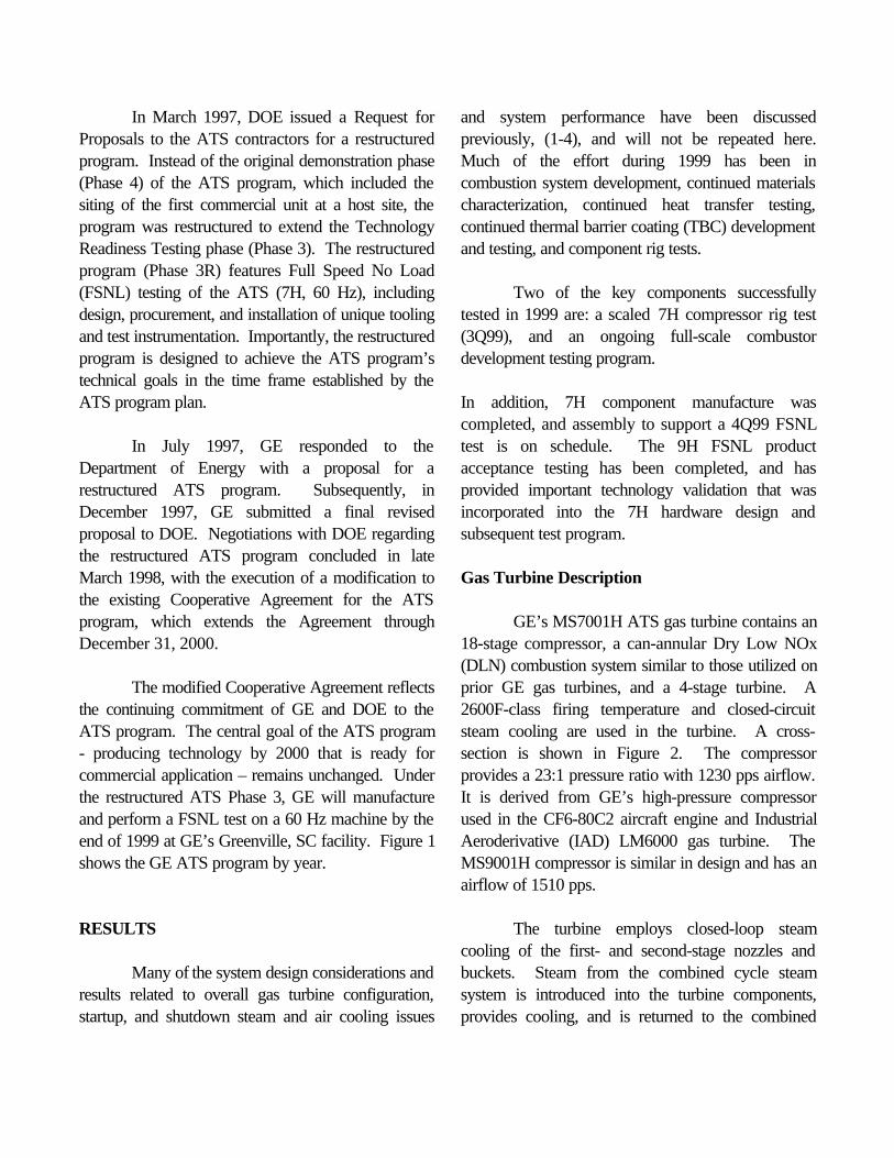
The 7H compressor rig test was completed in3Q99 at GEAE’s Lynn, MA test facility. Thecompressor rig rotor and stator are shown in Figure3.
MS7001H Compressor Test Results.The MS7001 compressor provides 1230 pps ofairflow at a 23:1 pressure ratio, and its design formsthe core aerodynamics for the 7H. This scales to 180pps and 23:1 pressure ratio for the test rig. Testobjectives included performance, operability, stallmargin, and aeromechanics. The rig was tested formore than 150 hours with more than 800 test pointsrecorded.
Power turndown performance and operabilitytesting were successfully conducted, with airflowturndown capability exceeding the 40 percent target.All of the compressor vibratory stresses were withinallowable limits.
An important part of the test wasestablishment of the high-speed compressor mapshown in Figure 4. In addition, testing was used tovalidate the no-load operating line, full-load operatingline, and stall margin. Start testing was performed tovalidate starting characteristics. The results of this testwere used to determine the variable vane settings inthe 7H FSNL test program.
The 7H compressor has been built upon afoundation of successful CF6-80C2 operation andvalidated by previous 9H compressor testing.
Rotor Steam Delivery System
The rotor steam delivery system deliverssteam for cooling stages 1 and 2 turbine buckets.This steam delivery system relies on tubular seals, or“spoolies”, to effectively deliver steam to the bucketswithout detrimental leakage of steam, which wouldlead to performance loss and adverse thermalgradients within the rotor structure. The basicconcept for power system steam sealing is derivedfrom many years of successful application of spooliesin GE aircraft engines.
Spoolies were used on the 9H FSNL testmachine. Although steam cooling was not utilized,assembly and disassembly tooling and processeswere developed. Post-FSNL test evaluation of theseals was correlated with previous spoolie componenttests.
A rotating steam delivery rig was designedand fabricated, and will demonstrate cyclic endurancecharacteristics of the steam delivery system undersimulated 9H and 7H engine operating conditions.The rotating rig will subject components to the samecentrifugal forces and thermal gradients that occurduring actual operation of the turbine. The rig isshown in Figure 5, and is scheduled to run in late4Q99.
Combustor Design
The H machine combustor design is based onthe current GE commercial DLN combustion system,with modifications being made for improved use ofavailable air, reduced cooling, and greater loadturndown capability. The design is similar for both the9H and 7H machines.
Development testing continued in 1999 in theGEAE-Evendale, OH combustor test facility, whichhas full H machine flow, pressure, and temperature

capability. Testing focused on producing acombustion system that produced single digit NOxemissions with acceptable dynamics, turndown, andmetal temperatures. Several configuration choiceswere made. The combustor length (longer of twooptions), and the number of fuel injectors perchamber were determined. Operating metaltemperatures were characterized, and lifing analyseswere completed with positive results. Testing willcontinue for the remainder of 1999 to develop marginto single digit NOx for the 7H. The combustor testrig is shown in Figure 6.
7H Full Speed No Load Test
The initial 7H full speed no load (FSNL)product acceptance test is scheduled for late 4Q99 atGE’s Greenville, SC manufacturing facility. Testingwill validate scale-up effects of the 7H compressor(flow, operability, aeromechanics), rotor dynamics,secondary airflow systems, bearing systems, andcontrols. The 7H FSNL test will benefit from theprevious 9H FSNL product acceptance test program,which provided an initial validation of the Htechnology platform and the GE Mark VI controlsystem. The 7H test machine is shown in Figures 7and 8.
Initial 9H Site
GE Power Systems and BP Amoco (UK) receivedBritish government approval for construction of a500-megawatt 9H-based power plant at the BaglanBay Energy Park in South Wales. The new plant isscheduled to enter service in 2002. An artist’s viewof the Baglan Energy Park is shown in Figure 9.
Initial 7H Site
GE Power Systems and Sithe Energies announcedplans for an 800-megawatt 7H-based power plant inScriba, NY. The plant is scheduled to begin
operation and testing in the last quarter of 2002. Anartist’s view of the “Heritage Station” plant is shownin Figure 10.
CONCLUSIONS
GE is continuing on its path to introduce the Hproduct line, providing the customer with the highestthermal efficiency, lowest cost of electricity option forfuture power generation. The successful compressorrig tests, nozzle cascade testing, and combustordevelopment are key milestones on that path. InitialFSNL testing of the 9H gas turbine at GE’sGreenville, SC manufacturing plant allowed validationof a large number of system components, and theresults are being factored into the ongoing 9H and 7Hdesigns. The MS7001H ATS will follow with FSNLtesting in late 1999.

ACKNOWLEDGEMENTS
DOE/FETC Contracting Officer’s Representative:Kanwal Mahajan
Period of Performance:July 1995 - December 2000
GE Power Systems, Schenectady, NY:Michael JamesKevin JerwannIain KellockRonald KorzunThomas LeRoyRobert OrensteinRichard Tuthill
REFERENCES
1. Cook, C. S. and Chance, T. F., November1996. Overview of GE’s H Gas TurbineCombined Cycle. Advanced TurbineSystems Annual Program Review, November7-8, 1996. Washington, DC.
2. Schonewald, R.W. and Fric, T.F., November1996. General Electric’s DOE/ATS H GasTurbine Development. Advanced TurbineSystems Annual Program Review, November7-8, 1996. Washington, DC.
3. Cook, C. S., November 1997. Overview ofGeneral Electric’s Advanced TurbineSystems Program. Advanced TurbineSystems Annual Program Review, October28-29, 1997. Morgantown, WV.
4. Cook, C. S., November 1998. Overview ofGeneral Electric’s Advanced TurbineSystems Program. Advanced TurbineSystems Annual Review, November 2-4,1998. Washington, DC.

Figure 1. ATS Program Timeline
Figure 2. 7H Gas Turbine
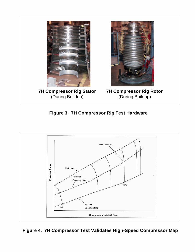
Figure 3. 7H Compressor Rig Test Hardware
Figure 4. 7H Compressor Test Validates High-Speed Compressor Map
7H Compressor Rig Stator(During Buildup)
7H Compressor Rig Rotor(During Buildup)

Figure 5. Turbine Rotor Rig
Figure 6. Combustor Test Stand at GEAE – Evendale, OH

Figure 7. 7H Compressor Rotor During Assembly
Figure 8. 7H Turbine Rotor During Assembly

Figure 9. 9H Site, South Wales, UKBaglan Bay Project
Figure 10. 7H Site at Heritage Station, Scriba, NY