overview of fluoropolymer foam technology - chemours · fep and pfa well suited for wire and cable...
TRANSCRIPT

Overview of Fluoropolymer Foam Technology
Wire New England ’07
WAI New England Chapter
October, 2007
Robert T. Young, DuPont Fluoroproducts

2
OutlineOutline
• Resin Structure and Properties
• General aspects of Foaming
• Equipment requirements for Foaming
• Resin, Construction & Processing Considerations
• Summary/Conclusion

3
Tefzel® ETFETefzel® ETFE -- CFCF22 -- CFCF22 -- CHCH22 -- CHCH22 -- nn-- 59% F59% F
Teflon® PTFETeflon® PTFE -- CFCF22 -- CFCF22 -- nn-- 76% F76% F
Teflon® FEPTeflon® FEP -- -- CFCF22 -- CFCF22 m CFm CF22 -- CFCF-- nn-- 76% F76% F
CFCF33
Teflon® PFATeflon® PFA -- -- CFCF22 -- CFCF22 m CFm CF22 -- CFCF-- nn-- 76% F76% F
OCOC33FF77
Structure & Properties of Structure & Properties of FluoropolymersFluoropolymers
• PTFE discovered in the 1930s but could not be melt extruded
• Modifications to polymer architecture led to the development of melt processable fluoropolymers such as FEP, PFA, FEP, PVDF
• Ability to be melt extruded coupled with properties such as a low dielectric constant and low flammability has made materials such as FEP and PFA well suited for wire and cable applications
PropertyProperty PTFEPTFE FEPFEP ETFEETFE PFAPFA
Specific GravitySpecific Gravity 2.152.15 2.152.15 1.701.70 2.152.15
Melting Point (2nd),°CMelting Point (2nd),°C 327327 260260 270270 310310
Tensile Strength, MPaTensile Strength, MPa 2020 2020 4040 2828
Elongation, %Elongation, % 300300 300300 300300 300300
Flexural Modulus, MPa Flexural Modulus, MPa 560560 650650 1,1001,100 650650
Temperature Rating,°CTemperature Rating,°C 260260 200200 150150 260260
Dielectric ConstantDielectric Constant 2.12.1 2.12.1 2.62.6 2.12.1
Coefficient of FrictionCoefficient of Friction 0.10.1 0.20.2 0.40.4 0.20.2
CutCut--Through, kgThrough, kg 4.54.5 4.5 4.5 1818 4.54.5
Chemical ResistanceChemical Resistance ExcellentExcellent ExcellentExcellent Very goodVery good ExcellentExcellent
* Nominal values* Nominal values
4
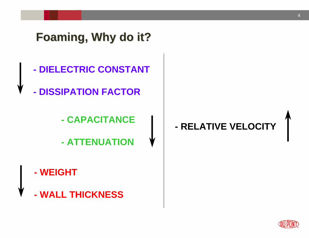
Foaming, Why do it?Foaming, Why do it?
- DIELECTRIC CONSTANT
- DISSIPATION FACTOR
- CAPACITANCE
- ATTENUATION
- RELATIVE VELOCITY
- WEIGHT
- WALL THICKNESS

5
VOID CONTENT, %
DIE
LEC
TR
IC C
ON
ST
AN
T2.6
2.5
2.4
2.3
2.2
2.1
2.0
1.9
1.8
1.7
1.6
1.5
1.4
1.3
1.2
1.1
1.00 10 20 30 40 50 60 70 80 90 100
FEP/PFA
POLYETHYLENE
ETFE
DIELECTRIC CONSTANT DIELECTRIC CONSTANT VERSUS VOID CONTENTVERSUS VOID CONTENT

6
Technology Implemented For FoamingTechnology Implemented For Foaming
1980
1985
1990
2000
Low PressureFreon ® Injection
Liquid Freon ®
Injection
High PressureNitrogen Injection
Low PressureNitrogen Injection

7
• Polymer is melted and conveyed ( Extruder )
• Gas is introduced into melt, forms solution
(Injector and High Pressure Pump )
• Ratio of polymer to N2 controls final product void Content
• Polymer/N2 solution exits Crosshead under
pressure
• Gas comes out of solution, forming bubbles
• Nucleating agents assist bubble formation
• Polymer cools on wire, freezing in structure
Mechanisms and Equipment for Mechanisms and Equipment for Foaming Foaming FluoropolymersFluoropolymers

8
Extruder ConfigurationExtruder Configuration
A traditional 3 to 4 stage screw is typically used
• Feed, Compression,Metering, and Mixing
• Typical compression ratio of around 3
A gentle mixing elements are recommended
• Low shear, divide & recombine elements beneficial in distributing the N2
Corrosion resistant materials of construction are needed
Extruder and screw design needs to be sized properly
• Too large (slow rpm) results in poor mixing and melting
• Too small (high rpm) can result in excessive shear and heat

9
Flow versus Pressure for Injector with 0.118 mil Nozzle
y = 0.0145x
R2 = 0.9989
40
60
80
100
120
140
2000 3000 4000 5000 6000 7000 8000 9000 10000
Pressure (psig)
Flo
w (
cc/m
in)
Gas Injection and MeteringGas Injection and Metering
Example of Injector (Maillefer Extrusion)
Example of high pressure gas pump (Fine International Corporation)
• Injector needs to be sized to deliver therequired gas flow at the desired pressure
• Flow to extruder controlled by orifice size & gas pressure supplied to the injector
• For stability, desirable to run injector pressures 1.5X to 2X higher than the barrel pressure
Metering Orifice

10
DieTip
WireFoaming
SlightMeltDraw
Melt Draw Extrusion Foamingfor Fluoropolymers
DieTip
WireFoaming
SlightMeltDraw
Melt Draw Extrusion Foamingfor Fluoropolymers
Profile Extrusion and DrawingProfile Extrusion and Drawing
• Ratio of the cross sectional areas of the annular tooling gap to that of the coating on the wire
• Lower DDR gives a more stable cone
• Higher DDR facilitates faster production rates
• DDR of 5:1 to 30:1 is typical
• Balance between the rates the outside and inside of the cone draw down
• R1 is die diameter divided by coated wire diameter
• R2 is tip diameter divided by bare wire diameter
• DRB = R1/R2
• DRB of 1.02 to 1.10 is typical
Drawdown Ratio (DDR)Draw Ratio Balance (DRB)
Optimum to have materialfoam once it is on the wire
Tooling calculations shouldbe based on the “pre-foamed”insulation diameter
11
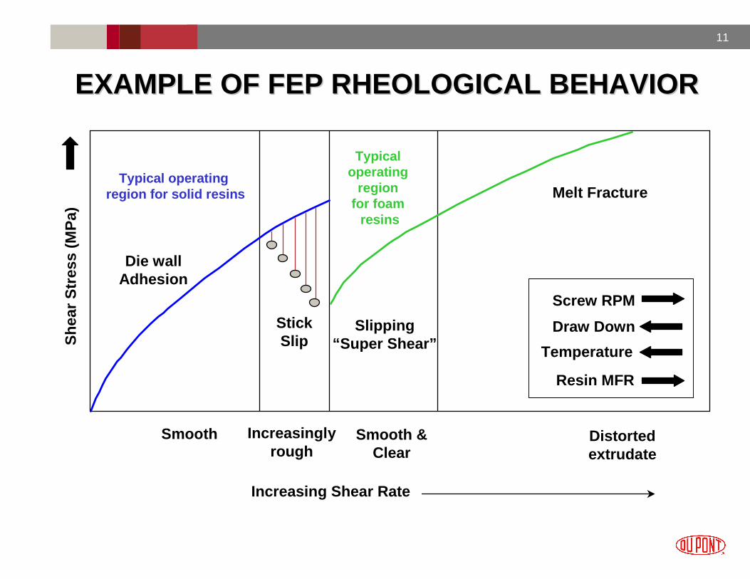
Increasing Shear Rate
Screw RPM
She
ar S
tres
s (M
Pa)
StickSlip
Die wallAdhesion
Slipping“Super Shear”
Melt Fracture
EXAMPLE OF FEP RHEOLOGICAL BEHAVIOR EXAMPLE OF FEP RHEOLOGICAL BEHAVIOR
Smooth Increasinglyrough
Smooth & Clear
Distorted extrudate
Draw Down
Temperature
Typical operating region for solid resins
Typical operating
region for foam
resins
Resin MFR

12
Construction ConsiderationsConstruction Considerations
Twisted Pair
Spacer
Jacket
Cat 5e
Cat 6
10 Gig
Jacket Spacer
Twisted Pair
Spacer
Jacket
Cat 5e
Cat 6
10 Gig
Jacket Spacer
• Resin and processing requirements highly dependent on construction
• Thicker wall (> 20 mil), higher void content (> 45%) constructions typically utilize lower MFR (< 15) resins and lower draw down tooling(RG cable, etc.)
• Thinner wall (< 20 mil), lower void content (< 45%) often made with higher MFR resins (> 15) and higher draw down tooling (Cat 6, 10 Gig, etc.)

13
Successful Foam = Good Return Loss/AdhesionSuccessful Foam = Good Return Loss/Adhesion
Return Loss measures the amount of signal that is l ost due to reflections along the length of the cable
14
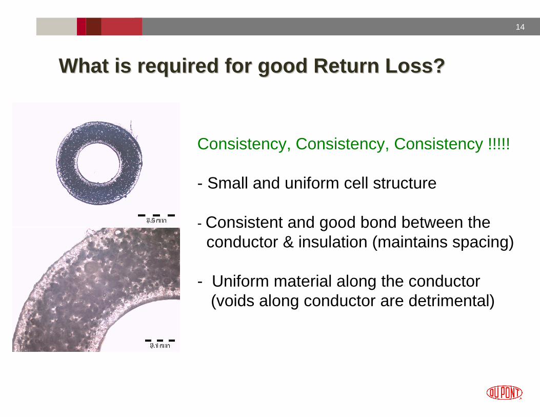
What is required for good Return Loss?What is required for good Return Loss?
Consistency, Consistency, Consistency !!!!!
- Small and uniform cell structure
- Consistent and good bond between the conductor & insulation (maintains spacing)
- Uniform material along the conductor(voids along conductor are detrimental)

15
Processing & Formulation = PerformanceProcessing & Formulation = Performance
• Good return loss can be achieved by combining material and processing parameters
• Polymer and nucleant formulation are contributing factors to producing uniform cells and better adhesion to the conductor

16
Variability in Diameter & Capacitance vs Nucleant P ackage
0.10%
0.15%
0.20%
0.25%
0.30%
0.35%
0.40%
0.45%
0.50%
0.55%
0.60%
Diameter Capacitance
CO
V %
(S
tand
ard
Dev
iatio
n/A
vera
ge)
Nucleant ANucleant B
Nucleant A
Nucleant B
Performance via FormulationPerformance via Formulation
• Nucleant type and loading can have an effect on processing and cell structure which impacts electrical performance
17
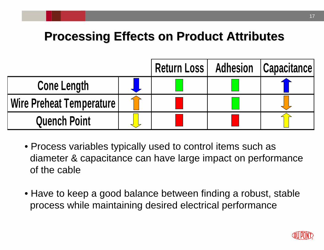
Return Loss Adhesion CapacitanceCone Length
Wire Preheat TemperatureQuench Point
Processing Effects on Product AttributesProcessing Effects on Product Attributes
• Process variables typically used to control items such as diameter & capacitance can have large impact on performance of the cable
• Have to keep a good balance between finding a robust, stable process while maintaining desired electrical performance

18
Alternative Methods for ProcessingAlternative Methods for Processing
Film / Foam / Skin
Film (Solid layer next to conductor)
• Provides void free uniform material next to the conductor• Serves to help improve return loss and adhesion
Skin (Solid layer on external Surface)
• Provide layer to help minimize blow through• Smoother surface for better contact for processes such
as shielding/braiding• Better processing control for items such as the cone
Foam / Skin

19
Summary and ConclusionsSummary and Conclusions
• Foaming of fluoropolymer resins such as FEP/PFAwith gas injection provides a safe & economical way to produce plenum rated cables of reduced size with desirable electrical performance
• Implementation of foamed products being facilitated with improvements in material formulations and processing technology
Makes for exciting times in the Wire and Cable Indu stryMakes for exciting times in the Wire and Cable Indu stry