overlay multicast for real-time distributed simulation
TRANSCRIPT
OVERLAY MULTICAST FOR REAL-TIME DISTRIBUTED SIMULATION
Final Report May 12. 2005
Dennis M. Moen Dr J. Mark Pullen
C3I Center, George Mason University
Submitted in Partial Fulfillment of Contract NBCH00-02-D-0037
Task Order 0217-001 Defense Modeling and Simulation Office

ii

iii
TABLE OF CONTENTS
Page ABSTRACT........................................................................................................................ x
XOM TOP-LEVEL ARCHITECTURE......................................................................... 1 I Introduction ..................................................................................................................... 1 II XOM Design Goals........................................................................................................ 3 III XOM High-Level Operational Concept........................................................................ 5 IV XOM System Functional Description ........................................................................ 18 V XOMR Routing Protocol ............................................................................................. 31 VI Summary..................................................................................................................... 39
APPENDIX A OVERLAY MULTICAST RESEARCH AND ANALYSIS.............. 40
SECTION I INTRODUCTION.................................................................................... 41 I Background.................................................................................................................... 41 II Statement of the Research Problem ............................................................................. 45 III Research Approach ..................................................................................................... 51 IV Summary and Unique Contributions of this Research ............................................... 52
SECTION 2 BACKGROUND AND SURVEY OF RELATED OVERLAY MULTICAST PROTOCOLS ........................................................................................ 55 I Introduction ................................................................................................................... 55 II Strategies for Overlay Multicast .................................................................................. 55 III Comparison of other Overlay Protocol Initiatives ...................................................... 60 IV Summary..................................................................................................................... 77
SECTION 3 BACKGROUND AND SURVEY OF RELATED ROUTING ALGORITHMS .............................................................................................................. 79 I Introduction ................................................................................................................... 79 II Algorithms Background ............................................................................................... 83 III Survey of Routing Algorithms.................................................................................... 86 IV Summary..................................................................................................................... 94
iv
SECTION 4 CHARACTERIZATION OF REAL TIME SIMULATION OFFERED MESSAGE LOAD .......................................................................................................... 95 I Introduction ................................................................................................................... 95 II Summary of Characterization Approach...................................................................... 95 III Analysis of Naval Vessel Simulation across Open Network using Web Services and XOM Prototype................................................................................................................. 98 IV Ops Simulation ......................................................................................................... 107 V JFCOM Message Transaction Analysis of JFCOM Simulation Experiment ............ 113 VI Summary of Observations for Message Flow Characterization ............................... 123
SECTION 5 MESSAGE LOAD ANALYTICAL MODEL ...................................... 126 I Introduction ................................................................................................................. 126 II Exponential Traffic Load Model................................................................................ 127 III ON/OFF Traffic Model............................................................................................. 136 IV Poisson Assumption.................................................................................................. 147 V Summary .................................................................................................................... 150
SECTION 6 PERFORMANCE CONSIDERATIONS FOR OVERLAY MULTICAST ................................................................................................................ 152 I Introduction ................................................................................................................. 152 II Performance Studies of the XOMR Prototype........................................................... 153 III Architecture Considerations...................................................................................... 162 IV Summary................................................................................................................... 166
SECTION 7 CONCLUSIONS, CONTRIBUTIONS, AND RECOMMENDATIONS FOR FUTURE RESEARCH ....................................................................................... 168 I Introduction ................................................................................................................. 168 II Conclusions ................................................................................................................ 168 III Unique Contributions of this Research ..................................................................... 170 IV Recommendations for Future Research.................................................................... 171
APPENDIX B END SYSTEM MULTICAST DEFINITION.................................. 174
APPENDIX C XOMR PROTOTYPE ........................................................................ 178
REFERENCES.............................................................................................................. 190
v
LIST OF TABLES Table Page Table 1: Function Definition/Operational Activity Matrix............................................... 20 Table 2: Data Element Description for XOMR (SV-4) .................................................... 22 Table A-2-1: Overlay Multicast Protocol Summary......................................................... 63 Table A-3-1: Comparison of Routing Algorithms............................................................ 91 Table A-4-1: Summary Statistics – JFCOM Simulation Experiment............................. 119 Table A-4-2: Message Flow Comparison ....................................................................... 125 Table A-5-3 Computer Simulation Results of Traffic Aggregation ............................... 148
vi
LIST OF FIGURES Figure Page Figure 1: High-Level Operational XOM Overlay Concept (OV-1) ................................... 7 Figure 2: XOM Operational Node Connectivity Description (OV-2) ................................ 9 Figure 3: XOM System Functional Description (SV-4) ................................................... 19 Figure 4: Group Aggregation Overlay.............................................................................. 25 Figure 5: Group Membership............................................................................................ 28 Figure 6: Registry Notional System Functional Description (SV-4)................................ 29 Figure 7: Registry UML Data Description (SV-4) ........................................................... 30 Figure 8: XMOR Host to Registry UML Data Description (SV-4).................................. 31 Figure A-4-1: Network Configuration for Web Service Interest Management................ 99 Figure A-4-2: Logical Tier Relationship for Multicast................................................... 100 Figure A-4-3: Message Flow from Federate to Multicast Group 2 ................................ 102 Figure A-4-4: WSIM Message Inter-Arrival Time......................................................... 103 Figure A-4-5: Message Flow from WSIM Server to Multicast Group 1........................ 105 Figure A-4-6: Tier View Message Flow......................................................................... 106 Figure A-4-7: Operations Simulation Experiment.......................................................... 109 Figure A-4-8: Tier View of Message Flow..................................................................... 110 Figure A-4-9: Message Throughput for the Ops Simulation .......................................... 111 Figure A-4-10: Ops Message Inter-Arrival Time ........................................................... 112 Figure A-4-11: Distributed Network .............................................................................. 114 Figure A-4-12: Typical Hierarchal Distribution ............................................................. 115 Figure A-4-13: Tier Relationship of Message Flow....................................................... 117 Figure A-4-14: Tier Relationship of Message Flow (Bytes) .......................................... 118 Figure A-4-15: Application Message Throughput Integrated View – Blue IMP 163 .... 121 Figure A-4-16: Tier View of Message Flow................................................................... 122 Figure A-5-1: State Transition Diagram......................................................................... 129 Figure A-5-2: Node Queue Model of Arrival Rates ....................................................... 132 Figure A-5-3: Example Network .................................................................................... 134 Figure A-5-4: Minimum Spanning ................................................................................. 135 Figure A-5-5: Two State Model for XOM Threshold Capacity ..................................... 144 Figure A-5-6: Plot of ( )
10log { [ ] / [ ]}mtVar X Var X versus ( )10log m ................................. 149
Figure A-6-1: Laboratory Test Scenario......................................................................... 154 Figure A-6-2: XOMR Loss Ratio (%) Performance Test............................................... 156 Figure A-6-3: Tier Processing Timing of Message Arrival............................................ 157 Figure A-6-4: M/D/1 Queue Waiting Time for Message Processing Time of 35 secµ . 160
vii
Figure A-6-5: M/D/1 Aggregate Probability Queue Overflow....................................... 161 Figure B-1: IP Multicast Tree resulting from DVRMP.................................................. 174 Figure B-2: Complete Graph connecting all Nodes........................................................ 175 Figure B-3: Spanning Tree of all Nodes ......................................................................... 176 Figure B-4: Physical Path of Packets across Spanning Tree .......................................... 176 Figure B-5: Proxy Nodes in an Overlay ......................................................................... 177 Figure C-1: XOMR Service on a Subnet ........................................................................ 179 Figure C-2: Group Aggregation Ovelay ......................................................................... 180 Figure C-3: JAVA Version of XOMR............................................................................ 184 Figure C-4: C++ Version of XOMR............................................................................... 186

viii
LIST OF ABBREVIATIONS/SYMBOLS ACE - Application Characterization Environment AS - Autonomous System ASM - Any Source Multicast ATM - Asynchronous Transfer Mode C3I - Command, Control Communications and Intelligence COI - Community of Interest DoD - Department of Defense DoDAF - Department of Defense Architecture Framework DiffServ - Differentiated Services DMSO - Defense Modeling and Simulation Office DREN - Defense Research and Engineering Network DVMRP - Distance Vector Multicast Routing Protocol GMU - George Mason University IP - Internet Protocol ISP - Internet Service Provider LAN{s} - Local Area Network(s) MMPP - Markov modulated Poisson Process MPLS - Multiprotocol Label Switching MST - Minimum-Weight Spanning Tree NETLAB - Network Modeling and Simulation Laboratory at George Mason University ODU - Old Dominion University OMNI - Overlay Multicast Network Infrastructure OPS-SIM - Operational Simulation OV-1 – High-Level Operational Concept Graphic defined by DoDAF OV-2 – Operational Node Connectivity Description defined by DoDAF P2P - Peer-to-Peer PC - Personal Computer PIM-SM - Protocol Independent Multicast – Sparse Mode QoS - Quality of Service RSVP - Resource Reservation Protocol RT-DVS - Real-Time Distributed Virtual Simulation RTI - Run Time Infrastructure RTT - Round Trip Delay SISO - Simulation Standards Interoperability Organization SRMP - Selectively Reliable Multicast Protocol SV-4 – System Functional Description as defined by the DoDAF TAG - Topology Aware Grouping

ix
VMASC - Virginia Modeling, Analysis and Simulation Center WSIM - Web Service Interest Management XML - Extensible Markup Language XOM - Extensible Modeling and Simulation Framework Overlay Multicast XOMR - Extensible Modeling and Simulation Framework Overlay Multicast Relay
x
ABSTRACT OVERLAY MULTICAST FOR REAL-TIME DISTRIBUTED SIMULATION This report provides a top-level architecture for an overlay multicast service in support of
distributed real-time virtual simulations over an open network environment. The top-level
architecture for the overlay protocol was developed based on key concepts identified in
the laboratory performance studies, the analytical model, and the studies of live
simulations. The proposed protocol is called the Extensible Modeling and Simulation
Framework Overlay Multicast Relay Protocol (XOMR). The XOMR provides overlay
multicast message relay services to support many-to-many communications in the very
dynamic environment of distributed real-time virtual simulation. (See Appendix B for
definition of overlay multicast.)
Appendix A includes results from demonstration of the prototype protocol based on
the top-level architecture. The results demonstrate that overlay multicast service is a
viable mechanism to meet the demands of communications messaging for distributed
real-time virtual simulation. A message traffic generator and test environment was
developed for use in performance evaluation of a prototype protocol used to demonstrate
feasibility for use of overlay multicast to support distributed real-time simulation.
xi
Appendix A also includes a description of an analytical model developed to
characterize the message flow characteristics to determine the regions of feasibility for
performance for overlay multicasting to support the target application environment. The
analytical model was validated in laboratory measurements of the prototype and the
results used to influence the design of the overlay protocol architecture.
Results of studies conducted of live real-time distributed simulations operating in the
laboratory and over the Defense Research and Engineering Network (DREN) are also
included in Appendix A. Included are results of studies and analysis of simulations in the
laboratory used to help characterize the operating system performance that might be
required to host the overlay protocol.
1
XOM TOP-LEVEL ARCHITECTURE
I Introduction
This report describes a top-level architecture for the XOM that recognizes that
underlying networks may have a wide range of network capacities and capabilities and do
not necessarily offer a multicast service. The proposed architecture provides a multicast
service to higher layer applications that require this capability across open networks. The
approach includes consideration for reliability by providing two classes of services on top
of existing UPD/IP protocols and security through a central registry service and
implementation of specific features within the protocol to support more secure
environments when required.
The research work described in Appendix A laid the ground work and describes the
basic principles for defining this architecture for the XOM to support many-to-many
multicast for RT-DVS applications. These applications have great demands for network
message throughput required for communicating object status updates [Brut02]. This may
consist of thousands of updates to simulation objects. A receiver set could be required to
support up to 10,000 simultaneous objects per group, and if the capability exists demand
could grow to scale up to millions. These object updates typically have message sizes in
the range of 100 to 200 bytes without tag or other protocol overheads. RT-DVS are run
on heterogeneous set of workstations with differing processing and display capabilities,
2
traveling over a heterogeneous network with capacities varying by many orders of
magnitude between the initial down link and the slowest end user.
The overlay multicast middleware is defined as the XOM Relay (XOMR) where relay
implies forwarding or routing of messages to designated destinations from authorized
sources. XOM uses an overlay multicast protocol designed to support efficient, reliable
many-to-many multicast transmissions on top of existing network protocols such as
UDP/IP for real time distributed visual simulations. It is based on the notion of a single
multicast host per subnet which controls all aspects of communications on a set of
multicast groups as a service to supported applications on that host’s subnet.
The simplest syntax definition for the protocol is that a message m is sent by process
p and the reception of m is by process q at one to many recipients. In order to add a level
of QoS, by queuing algorithm, the XOMR provides for the arriving of m at an incoming
channel from the application interface in an order which is a function of the priority of m
and provides for queuing on the sending side to the network, by process p.
The Department of Defense (DoD) Architecture Framework (DoDAF), Version 1.0 is
used as guide for the description and presentation of the top-level architecture for the
XOM. The Architecture begins with a discussion of overall design goals of the XOM
followed by an operational view in paragraph III. Paragraph IV provides system and
technical details of the top level architecture for the overlay multicast protocol. Paragraph
V follows with a proposed top-level description of the XOMR routing protocol.
3
II XOM Design Goals
The key design goals for the XOM are:
• XOM should not require support from underlying network routers or
operating systems in order to preserve ubiquitous deployment.
• XOM should be compatible with evolving IP and MPLS multicast services as
they are deployed in the Internet and be able to use these services
automatically in the underlying networks as they become available.
• XOM uses a central registry service and the location of the registry service
should not impact overall performance of the XOM.
• XOM will be self organizing in the sense that configuration is limited to
selecting a registry.
• XOM will be compatible/interoperable with existing IP multicast systems,
thereby preserving the high value invested in this approach within the
installed base.
• XOM will include security features to hence protection of multicast denial of
service attacks and provide information channel security when desired.
Good protocol design practices dictate the XOM:
• Use layered design to indicate the logical structure of the XOM protocol by
separating tasks. This defines the problem, the service to be performed at
every layer, the external functionality, and the internal functionality.
• Use routing middleware that is both scalable and decentralized, e.g., not
dependent on a central or root services for routing functionality.
4
• Is based on standards and portable abstractions of the system with network-
specific advantages including scalability, fault tolerance, and resource
availability easily utilized without any concerns about their underlying
infrastructure and resources.
• Transmission errors are handled at a higher layer (e.g. using the Selectively
Reliable Multicast Protocol (SRMP) [Pull99, Moen01] or at the application
layer).
• Use system aware messaging so that changes in system status can proactively
result in network/application adaptation.
• Is able to deliver/manage QoS to multiple simulation/applications.
• Use application knowledge of DVS to tailor design and implementation.
• Use local algorithms to collectively achieve a desired global effect. Example:
Some form of explicit congestion notification could be used for dynamically
regulating admitted real-time sessions in the face of network
congestion/network dynamics, to take advantage of the network awareness
characteristic of RT-DVS applications.
• Translate application level performance requirements into network
performance requirements.
Best practices for software system design calls for middleware that:
• Is light in computation and communication requirements.
• Is designed to intelligently trade the QoS of various demands against each
other.
5
• Identifies optimization metrics for use in resource allocation
• Is designed such that changes in topology and network conditions, even
node/link failures should not affect the operation of the control mechanism.
• Is designed not to keep per flow or aggregate state information, in order to not
have complex signaling for per flow state information as is the case might be
with “stateful” QoS approaches.
• Be administrator – friendly. Acceptance depends in part on the willingness of
administrators to deploy it, and for the software to be a good network citizen
that does not violate corporate security standards or take unfair advantage of
protocols that reduce information flow in order to control network congestion.
To maintain topology control of the overly the XOM must have ability to:
• Discovering neighbors
• Identifying position
• Determining transmission radius (diameter of the overlay)
• Establishing links to neighbors
• Maintain selected structure and information about nodes
• Information about service/node access (capacity)
III XOM High-Level Operational Concept
Many-to-many multicast transmission is an essential network capability for scalable
distributed simulation because the more common unicast approach does not scale. Here
we define many-to-many multicast to mean that many senders simultaneously can send to
6
all of many receivers. This also is called Any Source Multicast (ASM). Providing robust
multicast services to real time distributed virtual simulation (RT-DVS) is an important
requirement to enable use of Web based services across open networks such as the
Internet. These services must include network level quality of service (QoS) for
reliability and bounded latency as well as support for many-to-many multicast
communications.
A number of multicast protocols have been developed over several years to support
group communications. While these protocols offer many-to-many services, typical use
have focused on supporting applications that require only one-to-many data distribution.
Obvious examples include streaming audio and video. Even these early protocols have
had limitations in support of more demanding types of applications [Brau93].
RT-DVS applications use visual space management in real-time distributed
simulation and supporting communications systems and are evolving to Web based
services with XML tagged object characteristics. The performance provided by
underlying networks represent an important constraint in deployment of XMSF [Brut02].
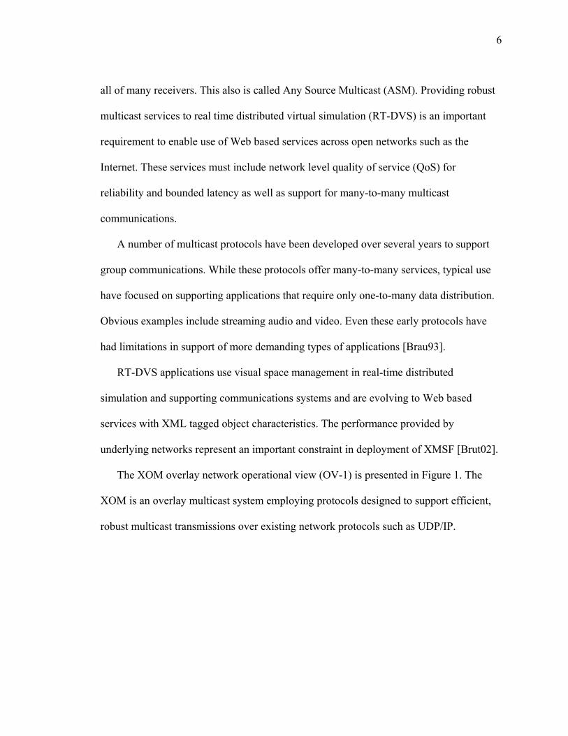
The XOM overlay network operational view (OV-1) is presented in Figure 1. The
XOM is an overlay multicast system employing protocols designed to support efficient,
robust multicast transmissions over existing network protocols such as UDP/IP.
7
Figure 1: High-Level Operational XOM Overlay Concept (OV-1)
Deploying RT-DVS across many organizations requires robust multicast networking
services that are invisible to end users. The proposed approach to XOM recognizes that
the underlying networks may have a wide range of network capacities servicing this
broad range of users that includes everything from low bandwidth wireless media to
modern broadband networks operating at gigabit speeds. The approach also recognizes
that, as RT-DVS applications move toward advanced technologies such as XML-oriented
Web services as well as agent-based distributed simulations [Wang03], there will also be
Router A
XOM1
Router
XOM4
XOM2
XOM3
Router C
XOM5
Router D
XOM6 XOM7
Application A
Application B
Application C
Application A Application B
Application B
Application C
Internet
Internet
8
a growing need for advanced networking services that are not likely to be available in
open networks such as the Internet [Moen03].
The XOM approach must provide the RT-DVS real-time response and predictable
network services in order for the end simulation systems to interact within specific delay
bounds. Simulations deployed across wide areas nevertheless require low latency,
including stringent jitter requirements and high bandwidth demands. Users also desire
simplicity in the sense that there should be very little configuration required to allow
deployment and establishment of service.
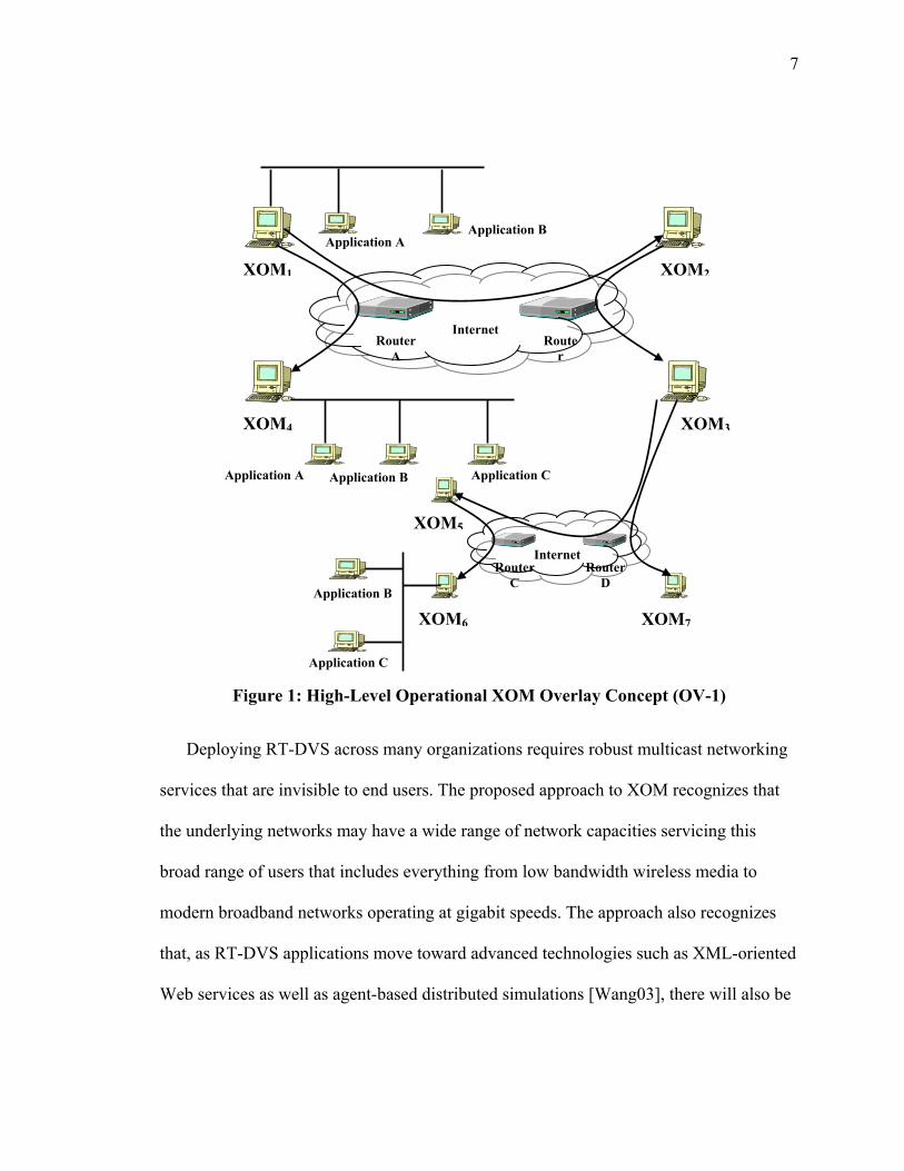
Figure 2 provides an Operational node Connectivity Description (OV-2) that depicts
the nodes, activities and information exchanges involved in overlay multicasting. The
filled rounded boxes represent nodes. The bullets in the rectangles between two nodes are
information exchanges. The bullets next to the node are activities preformed by the node.
Any number of nodes could participate in a community of interest overlay where each
node would perform the same function as the other organized to provide a multicast
service to the application layer.
9
Figure 2: XOM Operational Node Connectivity Description (OV-2)
XOMR
XOMR
XOMR
XOMR
Registry
Application
Application
Applicatio
Application
• Node discovery information exchange
• Group membership • Performance Statistics • Application messages
• Request for service • Authentication • Group membership • XOMR status
Application
Application
•Registry service communications •Overlay group membership filtering •QoS management •Performance measurement
•Maintain list of participants •XOMR Authentication •Group membership definition •Overlay administration
•Application messages

10
The following presents a summary of operational description for the XOM in four
categories: Group/overlay membership management, QoS, Path management, and
Security.
A. Group/Overlay Membership Management
This category requires the XOM to:
• Perform three basic functions in group management: address management,
service registration, and group membership maintenance.
• Provide registration services that identify the state of all XOMRs.
• Need to establish and manage membership in a multicast group which implies
assigning multicast group addressing scheme for the overlay. All multicast
traffic is then delivered to this address(s). This implies that all members of the
group must be listening for traffic with this address. In order to maintain
compatibility with existing IP multicast, the XOM allows for use of either
IGMPv2 or IGMPv3 locally to manage group membership. The organizational
community can choose which to use, but must be consistent across the
community. Using IGMPv3 allows implementation of source specific
multicast where a host joins specifically to a sender and group pair. This
capability allows some level of protection to the host from receiving messages
that it did not specifically request to receive.
• XOM doesn’t provide an inherent address management scheme, so an outside
authority (supported by the registry service in XOM) is required to provide the
11
address of the XOM host. Inherent to XOM this approach is a requirement for
an address assignment authority to support local served hosts and provide a
service to map multicast requests to an overlay IP path.
• There should be no explicit set-up processing between the sender and the
receivers beyond normal IP multicast group joins, prior to the establishment of
group communications. An out-of-band mechanism is required to pass the
multicast group (IP) address to the associated receivers. The receivers’
XOMR will have established support for the address prior to transmission in
order to receive the data.
• To add a new user to an existing group, the new receiver must first
communicate directly with the supporting XOMR using a mechanism to join a
group and exchange relevant information such as the group address. The
XOMR adds the new receiver, with the basic connection set-up processing
invoked as before, with the new connection completed only if there is
sufficient capacity to process the user.
• XOM group membership can be closed by either the sender or the receiver.
When the last receiver along a path has been removed, any resources allocated
over that path are released. When all receivers have been removed, the sender
is informed and has the option of either adding a new receiver or tearing down
the group.
• Connection set-up involves negotiation of the path capacity (access capacity)
and latency parameters between the sender’s XOMR, intermediate XOMRs,

12
and receiver XOMRs. If the requested resources cannot be made available, the
sender is given the option of either accepting what is available or canceling
the connection request.
B. Quality of Service
• Diversity and adaptability also must be accommodated by trading quality of
service (reliability. latency, and possibly jitter) with the capacity of the access
link. Multicast support for quality trades can be realized either through the use
of different multicast groups, and/or with prioritization of access capacity in
the overlay. Reliability for multi-class traffic can be accomplished through use
of a protocol such as SRMP, on top of the multicast overlay or queuing on the
send side based on class of traffic.
• The XOM does not provide a flow control mechanism in the context that
might be used for bulk data or file transfer. Some higher layer protocol is
expected to provide a flow control mechanism to regulate the quantity of data
placed on the network based on feedback from the XOM for bulk transfer
applications.
• The XOM provides rate control for access to the underlying network service.
The service is necessary to allocate available path resources and capacity in a
way that maintains the minimum negotiated QoS for the relay agent. Two
classes of service are supported: priority and best effort. Using two classes
provides a mechanism for application layer to designate priority under
13
congested or constrained conditions. The rate control mechanism also must
provide feedback to the higher layer protocol for application layer flow
control. The objective is to provide rate control from the global network
perspective based on the network resources used on a per flow or group basis.
• The XOM specification allows the user to determine whether multicast
transfers are unreliable or reliable, where reliable transfers are defined to
provide a "high-probability of success of delivery to all receivers.” SRMP can
provide the mechanism to manage this capability for limited amounts of
reliable traffic. SRMP, as a transport protocol, runs in the application host.
• The XOM, as an overlay, provides levels of guarantees end-to-end for
capacity and latency subject to availability in the underlying network. The
guarantees results from implementation of rate control where the XOM
dynamically manages the path, ensuring that the available capacity is
managed at optimum for the overlay. The enforcement policy ensures that the
same path is followed for all transmissions and prohibits new connections
over the network unless there is sufficient capacity to accommodate the
expected traffic. This is accomplished by maintaining the statistical state of all
connections in the XOMR.
• The XOM must acknowledge and be able to respond to the introduction of
priority messages above already allocated capacity. The approach is
implementation of a conservative statistical approach to capacity allocation
14
where bursts of priority traffic are allowed within the limits of the current
negotiated QoS [Simo03].
C. Path Management
• The XOM protocol suite requires routing support for four functions: path
setup, path teardown, packet forwarding, and prioritized packet loss due to
congestion.
• The routing tables must maintain both the multicast group address and the
forwarding path on each outbound interface in order to make appropriate
routing decisions.
• XOMRs receive path setup requests as required when new members join a
multicast group. This setup request specifies the incoming and outgoing
interfaces, the group address, and the QOS associated with the request. When
the message is received, XOMR establishes a path between the server and the
receiver, and subsequently updates the multicast group state table and
associated port information. Alternatively, the service can be aggregated
paths, and not provide sender based trees.
• Path teardown requests also are propagated through the XOMs when group
membership changes or QoS changes no longer require data to be sent over a
given route. These are used to inform XOMRs regarding both deletions of
QoS for a given path and deletions of entire paths. The purpose of the
message is to explicitly remove routing table entries in order to minimize the
15
time required to stop forwarding multicast data across networks once the path
is no longer required.
• Interface processes perform send and receive functions between XOMs across
the external network and with application hosts on the attached subnetworks
(LANS).
• The XOM provides a connectionless service which implies messages maybe
sent without permission; hence buffer management/overflow are required at
the receive side application layer.
• The XOM provides for two levels of priority traffic: Class B, no priority and
Class A, priority.
• Local control: relies on the existence of independent, end-to-end algorithms
that can “sense” and react to the distributed, local actions.
• Provide for resource management by periodically gathering and updating
information about the service/network.
D. XOM Security
Multicast communications introduce new security challenges compared to unicast
communication. RT-DVS multicast applications need source data authentication in order
to guarantee that a received message had originated from an authorized source and was
not manipulated during the transmission. There are a number of solutions available for
normal IP unicast communications. For example, a pairwise security association between
one sender and one receiver can provide data origin authentication using symmetric-key

16
cryptography. In groups, however, a key is required to be shared among more than two
members. In this case, a symmetric-key approach does not guarantee data origin
authentication. Since multicast implies group associations instead of pairwise, it becomes
possible for any member of the group to alter the message. It is therefore important that
security services design decisions for the XOM be an upfront design decision. It is
important to have security built in, not something added after the fact, includes
consideration for protecting the overlay, its members and for providing information
exchange protection.
If a systems approach is applied, then it is possible to use the concept of signatures to
detect and enable legitimate requests, denying all other traffic. The key security services
necessary are:
• Authentication—two processes exchange messages until each process is
certain that it is communicating with the other process
• Privacy—each of the processes uses its security key to encrypt any data
message before sending it to the other process
• Integrity—before sending a message, the sending process uses its security key
to compute an integrity check for the message and attaches it to the message.
This allows receiving process to prove the message arrived without
modification
• Non-repudiation—sending process computes digital signature to prove that
the message is from the sender
• Authorization—check for authorization to use a requested resource/process
17
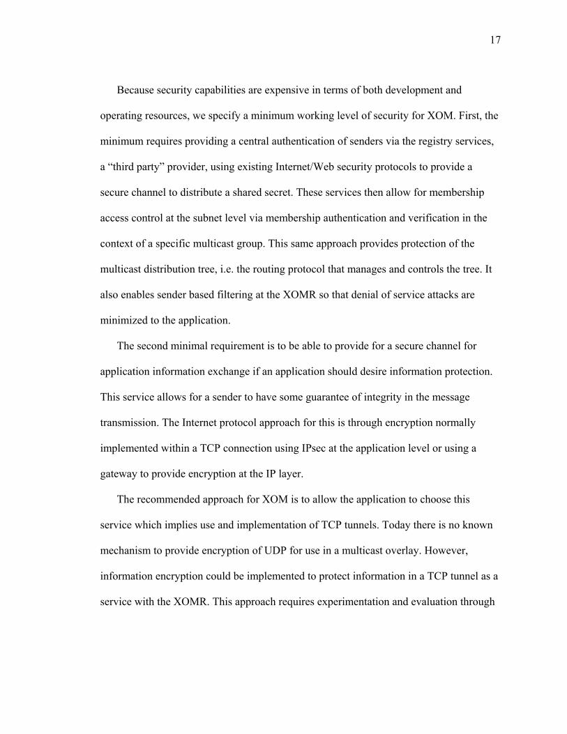
Because security capabilities are expensive in terms of both development and
operating resources, we specify a minimum working level of security for XOM. First, the
minimum requires providing a central authentication of senders via the registry services,
a “third party” provider, using existing Internet/Web security protocols to provide a
secure channel to distribute a shared secret. These services then allow for membership
access control at the subnet level via membership authentication and verification in the
context of a specific multicast group. This same approach provides protection of the
multicast distribution tree, i.e. the routing protocol that manages and controls the tree. It
also enables sender based filtering at the XOMR so that denial of service attacks are
minimized to the application.
The second minimal requirement is to be able to provide for a secure channel for
application information exchange if an application should desire information protection.
This service allows for a sender to have some guarantee of integrity in the message
transmission. The Internet protocol approach for this is through encryption normally
implemented within a TCP connection using IPsec at the application level or using a
gateway to provide encryption at the IP layer.
The recommended approach for XOM is to allow the application to choose this
service which implies use and implementation of TCP tunnels. Today there is no known
mechanism to provide encryption of UDP for use in a multicast overlay. However,
information encryption could be implemented to protect information in a TCP tunnel as a
service with the XOMR. This approach requires experimentation and evaluation through
18
prototyping so that performance can be measured and included in overall XOMR
performance expectations.
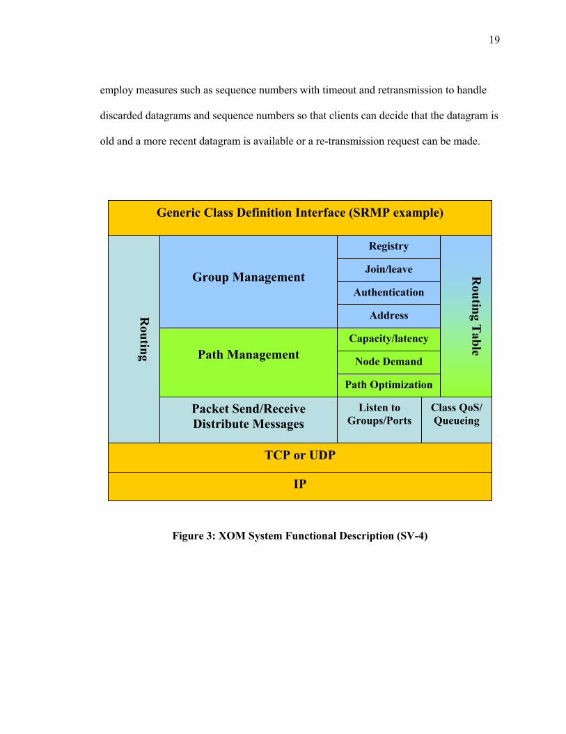
IV XOM System Functional Description
The system functional description (SV-4) for the XOM is presented in Figure 3 with
system function definition following in Table 1. Table 2 presents the data element
description for configuration of an XOMR to operate as a node in an overlay network.
The XOMR is designed so that each that module can be optimization and alternative
strategies for each can be prototyped for evaluation. The approach for the XOM overlay
is to use UDP as the underlying network protocol and offer services to the application
layer for two different classes of services: Class B-no priority and Class A-priority traffic.
The proposed XOM employs a priority queuing strategy to give priority to class A
traffic and mark class B traffic for discard eligible in the event of network congestion.
This approach is consistent with our previous efforts in development of multicast
protocols such as the SRMP.
Since this approach does not provide error control, any form of desired error control
must be added to the client application. The design assumption is that packets are
relatively small (<200 bytes) and the underlying network is able to deliver packet
guarantees greater than 99% and has reasonable routing path stability on the order of
minutes. Reliable transport can also be provided using higher layer protocols such as
SRMP, shown in Figure 3 as an example interface, where a more desirable reliability is
sought but not available to the client application. Alternatively, the application can
19
employ measures such as sequence numbers with timeout and retransmission to handle
discarded datagrams and sequence numbers so that clients can decide that the datagram is
old and a more recent datagram is available or a re-transmission request can be made.
Figure 3: XOM System Functional Description (SV-4)
Generic Class Definition Interface (SRMP example)
Packet Send/Receive Distribute Messages
Listen to Groups/Ports
Class QoS/ Queueing
Routing T
able
Registry
Join/leave
Authentication
Address
Group Management
Capacity/latency
Node Demand
Path Optimization
Path Management
Routing
TCP or UDP
IP
20
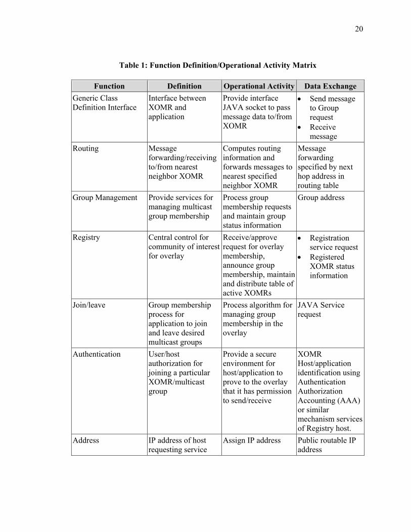
Table 1: Function Definition/Operational Activity Matrix
Function Definition Operational Activity Data Exchange Generic Class Definition Interface
Interface between XOMR and application
Provide interface JAVA socket to pass message data to/from XOMR
• Send message to Group request
• Receive message
Routing Message forwarding/receiving to/from nearest neighbor XOMR
Computes routing information and forwards messages to nearest specified neighbor XOMR
Message forwarding specified by next hop address in routing table
Group Management Provide services for managing multicast group membership
Process group membership requests and maintain group status information
Group address
Registry Central control for community of interest for overlay
Receive/approve request for overlay membership, announce group membership, maintain and distribute table of active XOMRs
• Registration service request
• Registered XOMR status information
Join/leave Group membership process for application to join and leave desired multicast groups
Process algorithm for managing group membership in the overlay
JAVA Service request
Authentication User/host authorization for joining a particular XOMR/multicast group
Provide a secure environment for host/application to prove to the overlay that it has permission to send/receive
XOMR Host/application identification using Authentication Authorization Accounting (AAA) or similar mechanism services of Registry host.
Address IP address of host requesting service
Assign IP address Public routable IP address
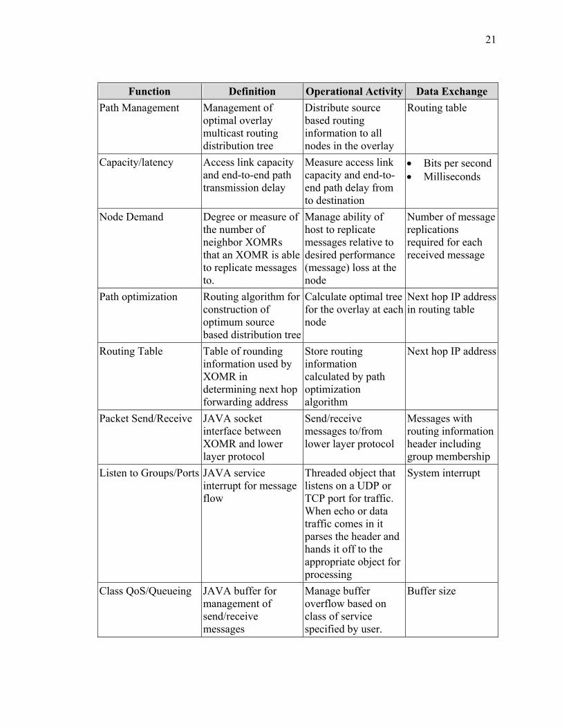
21
Function Definition Operational Activity Data Exchange Path Management Management of
optimal overlay multicast routing distribution tree
Distribute source based routing information to all nodes in the overlay
Routing table
Capacity/latency Access link capacity and end-to-end path transmission delay
Measure access link capacity and end-to-end path delay from to destination
• Bits per second • Milliseconds
Node Demand Degree or measure of the number of neighbor XOMRs that an XOMR is able to replicate messages to.
Manage ability of host to replicate messages relative to desired performance (message) loss at the node
Number of message replications required for each received message
Path optimization Routing algorithm for construction of optimum source based distribution tree
Calculate optimal tree for the overlay at each node
Next hop IP address in routing table
Routing Table Table of rounding information used by XOMR in determining next hop forwarding address
Store routing information calculated by path optimization algorithm
Next hop IP address
Packet Send/Receive JAVA socket interface between XOMR and lower layer protocol
Send/receive messages to/from lower layer protocol
Messages with routing information header including group membership
Listen to Groups/Ports JAVA service interrupt for message flow
Threaded object that listens on a UDP or TCP port for traffic. When echo or data traffic comes in it parses the header and hands it off to the appropriate object for processing
System interrupt
Class QoS/Queueing JAVA buffer for management of send/receive messages
Manage buffer overflow based on class of service specified by user.
Buffer size
22
Function Definition Operational Activity Data Exchange TCP or UDP Internet transport
protocol specifying type of service and flow control
Transform application message to meet Internet protocol specification for IP layer using UDP or TCP based tunnels.
• UDP protocol format for best effort service
• TCP tunnels for streaming data and IP based encryption
IP Internet Protocol Message routing across Internet (open network)
IP packets specified by IETF format
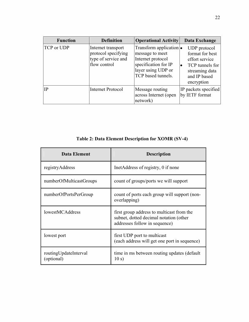
Table 2: Data Element Description for XOMR (SV-4)
Data Element Description
registryAddress InetAddress of registry, 0 if none
numberOfMulticastGroups count of groups/ports we will support
numberOfPortsPerGroup count of ports each group will support (non-overlapping)
lowestMCAddress first group address to multicast from the subnet, dotted decimal notation (other addresses follow in sequence)
lowest port first UDP port to multicast (each address will get one port in sequence)
routingUpdateInterval (optional)
time in ms between routing updates (default 10 s)
23
Data Element Description
thisSubnetMaskBits (optional) number of bits used for routing in subnet address (default 24)
useTCP (optional) 0 for UDP tunnels, 1 for TCP tunnels (default 0)
partnerHostAddress (optional in future, when Registry becomes available)
zero to MAX_PARTNERS IP addresses, in dotted decimal format, to be used as partners without checking the registry
The core of the XOM is provided in the Group and Path management functions as the
result of these activities provide the information for the routing table to be used in
making packet forwarding (routing) decisions. Three approaches should be considered
for managing the multicast path overlay and associated groups:
1. The XOMs could provide a service that is independent of group management and
essentially provide a path(s) overlay optimized across an open network to other
registered XOMs. Under this model, the path overlay looks like a closed network
with all group communications provided as single multicast network similar to
Protocol Independent Multicast – Sparse Mode (PIM-SM) specification [Estr98].
Each user application of the XOM, then listens for desired group identification
communications broadcasted on the local area network hosting the XOM and
discards/ignores unintended traffic.
2. The XOM could provide a service that recognizes group membership dynamics
(registered XOMs that host users/applications identified by group) and provide an
24
overlay path optimized for each group. This approach generally is referred to as
source-based tree multicast [FeiA01].This implies management and optimization
of multiple paths, essentially a path structure for each registered multicast group.
The current XOMR prototype uses this approach.
3. The XOMR can provide a service that aggregates group traffic across optimized
paths between XOMRs as presented in Figure 4. These optimized paths are
essentially shared trees and can be optimized for capacity and delay to support
aggregated group traffic [CuiJ04]. (See Appendix B for description of concept for
building overlay trees.) This approach also is similar to aggregated group
multicast over MPLS [CuiJ04] and with added features for group management.
The current XOMR prototype performs aggregation.
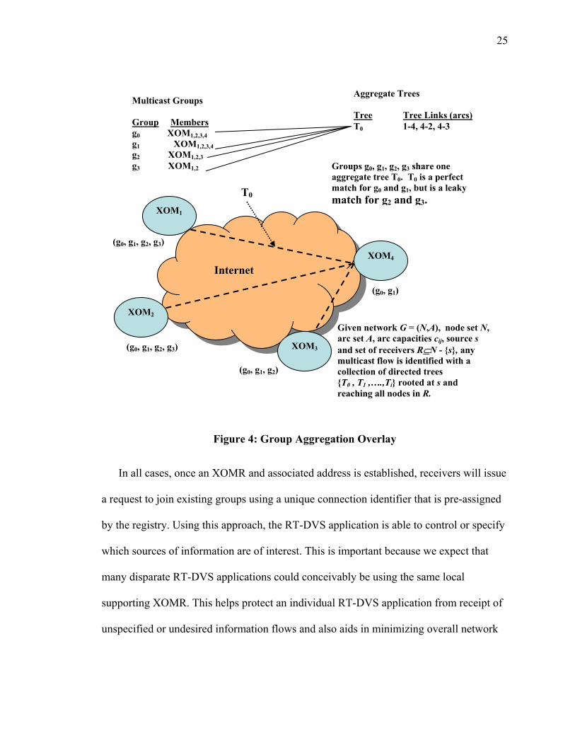
25
Figure 4: Group Aggregation Overlay
In all cases, once an XOMR and associated address is established, receivers will issue
a request to join existing groups using a unique connection identifier that is pre-assigned
by the registry. Using this approach, the RT-DVS application is able to control or specify
which sources of information are of interest. This is important because we expect that
many disparate RT-DVS applications could conceivably be using the same local
supporting XOMR. This helps protect an individual RT-DVS application from receipt of
unspecified or undesired information flows and also aids in minimizing overall network
Multicast Groups Group Members g0 XOM1,2,3,4 g1 XOM1,2,3,4 g2 XOM1,2,3 g3 XOM1,2
Aggregate Trees Tree Tree Links (arcs) T0 1-4, 4-2, 4-3
XOM2
XOM4
XOM3
XOM1
Internet
(g0, g1, g2, g3)
(g0, g1)
(g0, g1, g2)
(g0, g1, g2, g3)
T0
Groups g0, g1, g2, g3 share one aggregate tree T0. T0 is a perfect match for g0 and g1, but is a leaky match for g2 and g3.
Given network G = (N,A), node set N, arc set A, arc capacities cij, source s and set of receivers R⊆N - {s}, any multicast flow is identified with a collection of directed trees {T0 , T1 ,….,Ti} rooted at s and reaching all nodes in R.
26
traffic load. This will require that we specify how the XOM identifier is allocated and
how the receivers learn its value the external registry service and supporting protocol.
At the local level, the XOM manages the receivers’ interests in receipt of group
messages. This feature allows for a host to report to the local XOMR interest in receiving
packets only from specific source addresses and therefore aids in the overall management
of group membership and optimization of traffic loads on the network. This approach
also potentially adds a level of security to the RT-DVS application as the application is
able to discard or ignore messages from unauthorized sources.
We allow for the join request from a RT-DVS application to specify whether the
receiver wishes to be a producer of information as well as a receiver, whether the
connection should be able to provide the two classes of service (no priority or priority),
whether the receiver is able to accept multiple senders of information, the minimum
throughput desired, and the maximum data message size. This request information is
presented to the supporting XOM and used in the group join process to support
negotiation of the path capacity and latency parameters among the sender XOM,
intermediate XOMs, and receiver XOMs. If the needed resources to support the request
cannot be made available, the sender is given the option of either accepting what is
available or canceling the connection request.
An application request for terminating membership in a group is coordinated through
the supporting XOM. XOM connections can be closed by either the sender or the
receiver. When the last receiver along a path has been removed, the resources allocated

27
over that path are released. When all receivers have been removed, the sender is informed
and has the option of either adding a new receiver or tearing down the group.
We have not included in the specification what action the local XOM should take
when the application group is reduced to a single member, but a logical action would be
to stop transmission if there are no active receivers and announce this to the registry
service. It is also possible that the XOMRs will discover this by communicating with
each other, rather than via the registry. In this case, the routing protocol will prune a
dead-end XOMR from the routing tree but keep an XOMR if it is making the tree more
efficient by providing a branching point.
Our group membership approach assumes that a group definition is based on a
specific application running behind an XOM on the local area network. Multiple
instances of an application are supported behind each XOM, each of which may have
different group membership characteristics to include membership in multiple groups. It
is also feasible for a RT-DVS application to have membership in more than one group.
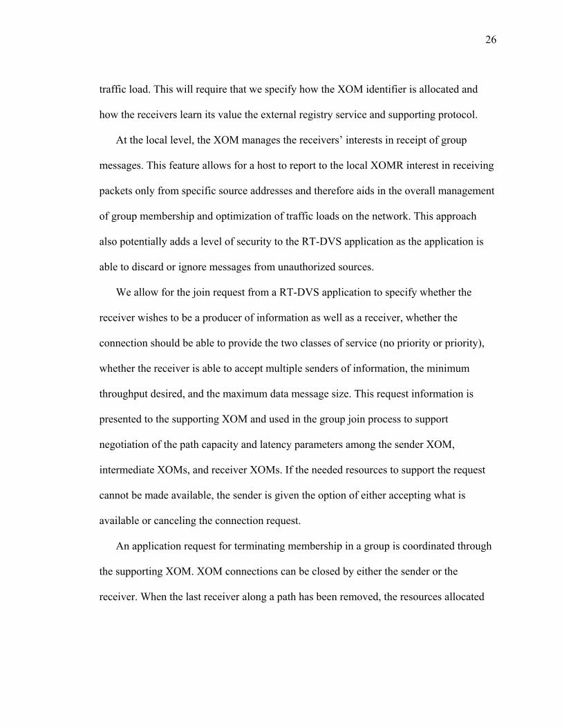
We present an example in Figure 5. Notice that application B has membership in group 1
and in group 2. In order to maintain efficiencies in packet transmission, we form a new
group 3 that is the union of the two groups. We also imply no explicit set-up processing
between the sender and the receivers prior to the establishment of group communications.
The XOM mechanism is required to pass the multicast group (IP/group tag) address to
the XOMRs of the associated receivers. The receivers’ XOM must have established
support for the address prior to transmission in order to receive the data.
28
Figure 5: Group Membership
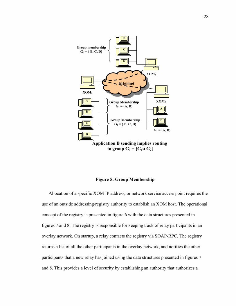
Allocation of a specific XOM IP address, or network service access point requires the
use of an outside addressing/registry authority to establish an XOM host. The operational
concept of the registry is presented in figure 6 with the data structures presented in
figures 7 and 8. The registry is responsible for keeping track of relay participants in an
overlay network. On startup, a relay contacts the registry via SOAP-RPC. The registry
returns a list of all the other participants in the overlay network, and notifies the other
participants that a new relay has joined using the data structures presented in figures 7
and 8. This provides a level of security by establishing an authority that authorizes a
XOM3
Internet
A B C D
A
B
C
D
Group Membership G1 = {A, B}
Group Membership G2 = { B, C, D}
B
G1 = {A, B}
Group membership G2 = { B, C, D}
Application B sending implies routing to group G3 = {G1υ G2}
XOM1
XOM2
29
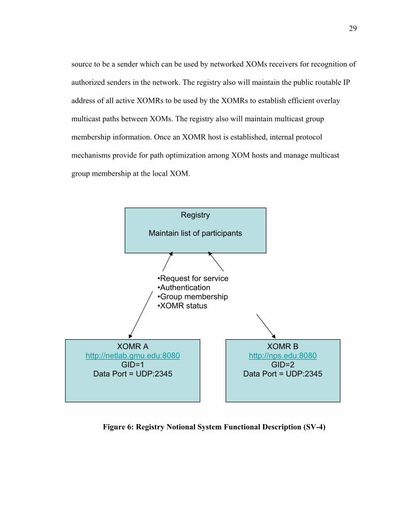
source to be a sender which can be used by networked XOMs receivers for recognition of
authorized senders in the network. The registry also will maintain the public routable IP
address of all active XOMRs to be used by the XOMRs to establish efficient overlay
multicast paths between XOMs. The registry also will maintain multicast group
membership information. Once an XOMR host is established, internal protocol
mechanisms provide for path optimization among XOM hosts and manage multicast
group membership at the local XOM.
Figure 6: Registry Notional System Functional Description (SV-4)
Registry
Maintain list of participants
XOMR A http://netlab.gmu.edu:8080
GID=1 Data Port = UDP:2345
XOMR B http://nps.edu:8080
GID=2 Data Port = UDP:2345
•Request for service •Authentication •Group membership •XOMR status
30
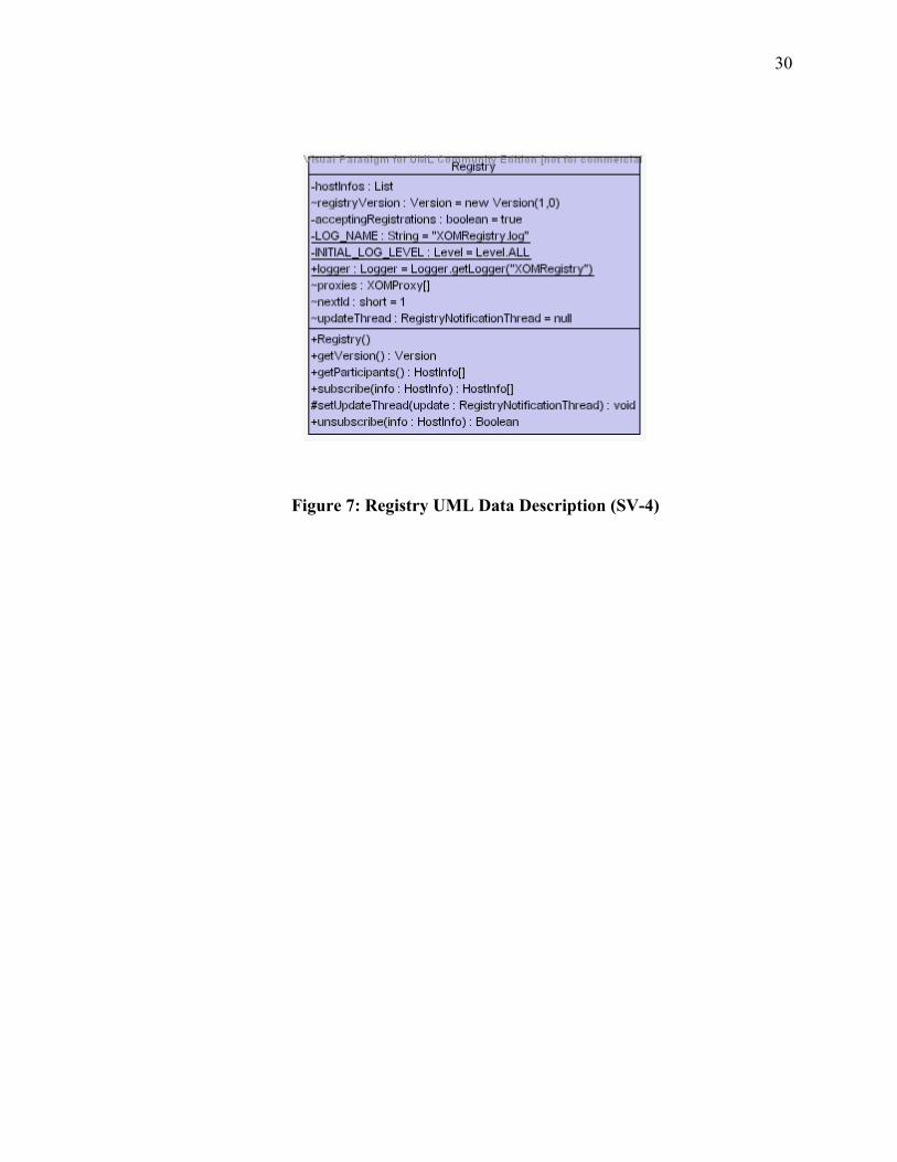
Figure 7: Registry UML Data Description (SV-4)
31
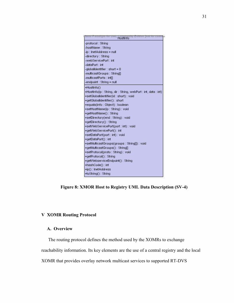
Figure 8: XMOR Host to Registry UML Data Description (SV-4)
V XOMR Routing Protocol
A. Overview
The routing protocol defines the method used by the XOMRs to exchange
reachability information. Its key elements are the use of a central registry and the local
XOMR that provides overlay network multicast services to supported RT-DVS
32
applications. The registry maintains a list of all XOMRs in the network and registered
RT-DVS application users with their requested group membership, but is not required to
maintain the topology of the overlay. The only requirements are that the registry
responds/replies to all requests from an XOMR and any valid XOMR can send messages
at least to its neighbors in the overlay network.
XOM relies on three steps to build the overlay. The first step is that a joining XOMR
must send a request to the registry access to the overlay. Second, the XOMR must
discover neighbor XOMRs that are potential candidates for the joining XOMR to
establish a network connection with, essentially building and becoming part of an overlay
mesh. The third step is for the joining XOMR to establish the services necessary for
group management and exchange this information with networked XOMRs, calculate
(and update routing table) optimum paths (shortest path tree) for group multicast routing
from source to group destinations, and propagate that routing to all other XOMRs.
There are two mechanisms that contribute to global service guarantees. The first is to
limit the out degree of an XOM host using Bollobas’ definition of the degree of a vertex
[Boll01]. That is, we do not allow the construction of more than n connections to other
XOMRs. This serves to limit the processing demands and network access capacity of
individual XOMRs in the overlay. The second is to threshold the end-to-end overall path
delay from a sending XOMR to a destination XOMR and offer only best effort above this
threshold to joining XOMRs that do not successfully find an existing XOMR node that is
adequate to maintain end-end-to-end path delay thresholds (e.g. 110msec threshold in
networking latency, based on the fact that 150 msec is representative of human response
33
times for RT-DVS. This can also be accomplished by establishing a network diameter
threshold based on Bollobas’ definition of network diameter [Boll01].).
We provide congestion control by providing two levels of service to the RT-DVS
application. Class B packets have no priority and Class A packets have priority. We
apply weighted fair queuing giving priority to Class A packets in the send queue of the
XOMR and discard Class B packets randomly during congestion.
Since the XOMR is hosted on the LAN that connects to the supported RT-DVS
application, we use IGMPv3 [Cain02] for group management at the local level.
B. Network Protocol
1. Central Registry. A central registry provides a service to register the presence of
a XOMR and the participation of an RT-DVS application. The central registry
maintains a cache of all nodes participating in the overlay.
a. The registry maintains the IP address of the XOMRs and authenticates and
audits continued participation in the overlay.
b. The central registry is reachable by all XOMR nodes at all times.
c. In the request for join by a new XOMR, the exchange messages will
provide for measurement of round trip delay time (RTT) between the
registry and the joining XOMR. The registry will maintain this time and
periodically update the information.
d. On request of a new XOMR to join the network, the registry will provide
the joining XOMR the addresses of existing XOMRs. The XOMR then
34
randomly polls the existing set of XOMRs measuring the RTT. The
responses with the shortest RTT represent the initial best candidates as the
nearest neighbors in the overlay. The XOMR continuously performs
random polling of known member XOMRs of the overlay, always looking
to optimize the selection of best neighbors.
e. The registry provides for registration of the RT-DVS application,
authenticates and authorizes relationship to a serving XOMR as a
legitimate source/sender, assigns a node ID, and maintains group
membership participation based on RT-DVS application request.
f. The registry group management service provides for creation of a
multicast group and assigns a group ID using the IP multicast address as
the group ID. This information is then made available for source and
receiver RT-DVS applications. A joining host source/receiver application
can then use the information locally to indicate to the XOMR a desire to
join a group by providing the group ID to the XOMR (XOMRs will use
IGMP for this function locally) [Bhat03].
2. XOM Overlay Construction. The XOM constructs an overlay using a
decentralized algorithm by searching for potential target existing network
XOMRs to become the child of in the overlay (nearest neighbor). It uses measures
of RTT to candidate neighbors to make decisions on joining a parent already in
the network.
35
a. An XOMR ready to join a multicast overlay sends a request to the registry
indicating desire to.
b. The registry authenticates the XOMR against a previously established
authorization in the registry and responds to the joining XOMR with a list
of all XOMRs in the existing network supporting the desired group
membership.
c. The XOMR sends echo requests to N candidate XOMR partners resulting
in RTT replies.
d. If the candidate XOMR existing connections are less than n, the parent
XOMR responds with a message indicating availability or else ignores the
message.
e. The joining XOMR uses the message exchange to measure RTT to the
candidate(s) partner XOMR(s). With the RTT information, the joining
XOMR selects the best candidate as the primary connection and selects
the second best as an alternate path and responds to these potential parents
with acknowledgement of the selected connection and ignores all other
responses. The primary partner and the alternate send acknowledgements
to the joining XOMR to complete the network join process.
f. The partner XOMR updates the routing table to reflect the new neighbors
with measured latency and propagates this information to all its neighbors
in the overlay. The result is a connected graph.
36
g. The XOMR uses the designated primary path unless it is not available in
which case it uses the alternate neighbor connection.
h. The XOMR maintains a routing table which maps a node ID to the node
IP address and next hop, e.g. neighbor along the path to the distant node.
i. Periodically each XOMR sends heart beat probe messages to its neighbors
to determine if the neighbor is still connected and if necessary, initiates the
node join process in the case of disconnected nodes by sending a request
to the registry, or by probing known XOMRs in the network.
j. Periodically, each XOMR sends random discover messages to other
known XOMRs to discover if a better neighbor (link cost) is available and
makes decisions on alternate path choices over using the current path. To
support this, the registry must periodically update the list of known
XOMRs in the overlay.
3. Link Delay Measurement. The XOMR develops the link delay data between
itself and its neighbors by measuring RTT. This information is shared with the
XOMR neighbors and propagated across the overlay.
a. The XOMR collects link delay information shared and periodically
updated from neighbor XOMR.
b. The link information is propagated across the overlay so that each XOMR
will have knowledge of primary and alternate link delay information
between XOMR nodes in the connected graph. It is not necessary to know
each link weight in the graph, if all the nodes in the graph have distinct
37
identities. However, distributed minimum spanning trees are constructed
with fewer messages if this knowledge exists at the source node [Gall83].
4. Multicast Tree construction. The overlay constructed by the distributed
algorithm is a connected undirected graph with N nodes and E edges, with a finite
weight assigned to each edge. A distributed algorithm is used at each node to
determine the minimum-weight spanning tree (MST)
a. We desire the algorithm to optimize overall performance across the entire
overlay. This means optimizing certain objective functions to improve
overall quality of message delivery. This quality is typically measured in
terms of latency and message loss. The algorithms solve a shortest path
problem potentially with many constraints to build a tree connecting the
source(s) and destination group members so that minimal message flow
occurs in the distribution of the message as well as maintaining optimum
or minimum latency form source to each destination. The optimal case is
that only a single copy of the message flows on any link in the overlay,
meets application latency requirements, and offers some level of
reliability. Typical resources that are allocated or that must be optimized
are link capacity, host processing capacity, number of links or diameter of
the tree, and the degree of a node in the path overlay. In addition, the
algorithm must lend itself to supporting dynamic overlays where many
multicast group members join and leave in real-time. It is also important to
consider the scalability of the algorithm which is made considerably more
38
difficult because end systems typically have limited topological
information in which to construct good overlay paths. All these factors are
considered in the optimization. A number of algorithms have been
considered, for example the constrained Steiner tree [Komp92] and
distributed delay bond algorithms [JiaX98]. If we run the optimization
algorithm at each node, we obtain aggregate multicast paths from each
XOMR as a sender to all other XOMRs.
b. The addition of a new node requires the new node initially join as a child
node as described in the XOMR overlay construction procedure above.
The join information is propagated to neighbor nodes and the new node
runs the distributed shortest path algorithm and sends routing table updates
to the XOM overlay.
5. Node Departure. There are two cases for node departure. A network event may
result in the XOM not being available in the overlay, in which case, the routing
algorithm must be able to repair the overlay using the alternate link to nearest
neighbor. In the second case, an XOMR may no longer have supported group
members and at some point may desire to log off the overlay. This case represents
a soft leave and allows for message exchange to effect new path construction
without the disruption of service.
39
VI Summary
Widely deploying RT-DVS across many organizations with large numbers of
applications requires robust multicast networking services that are transparent to end
users. This report has described a top-level architecture for the XOM that recognizes that
underlying networks may have a wide range of network capacities and capabilities and do
not necessarily offer a multicast service. The proposed architecture provides a multicast
service to higher layer applications that require this capability across open networks. The
approach includes consideration for reliability by providing two classes of services on top
of existing UPD/TCP/IP protocols.
The overlay multicast middleware is defined as the XOMR where relay implies
forwarding or routing of messages to designated destinations from authorized sources. A
relay host resides on every subnet that is host to applications that desire multicast services
between them. The XOMR host provides all controls and management services necessary
to provide the multicast service. The architecture includes provisions for a registry
service that enables security features so that only known XOMRs have access.

40
APPENDIX A OVERLAY MULTICAST RESEARCH AND ANALYSIS
41
SECTION I INTRODUCTION
I Background
Distributed virtual simulations operating across a network in human time generate
large amounts of message traffic between the computers hosting the simulation
applications. This requires many-to-many communications in a dynamic group
environment where N computers in the group scales as O(N) message transmissions from
each member or O(N2) total message transmissions in the group [Pull99]. In addition, this
simulation environment may not necessarily be homogenous, e.g. each simulator is likely
to be different but they dynamically share common simulation objects over time. The
result is that simulation objects may have membership in multiple groups with each
group’s membership changing at different rates.
RFC2502 [Pull99b] describes key networking requirements for distributed simulation
that result from the interaction of humans participating in these simulations in real-time.
Networks supporting these must distribute large amounts of data within the bounds of the
human interaction time which leads to the need for specific delay bounds. The
environment requires many-to-many distributions of data where many senders are
sending to many receivers simultaneously. This environment can be described as a
multiparty collaborative environment supporting multimedia applications. The underlying
42
networking environment needs to support a large number of participants dynamically
joining and leaving the communicating groups across the myriad of public and private
networks that make up the Internet. Because each of these networks is independently
managed, the Real-Time Distributed Virtual Simulation (RT-DVS) applications cannot
solely rely on the Internet to deliver the necessary Quality of Service (QoS) even though
QoS mechanisms are beginning to become available. As a result, networking real-time
simulators together has seen limited deployment, and then only in specialized local area
networks or on private networks dedicated to the simulation environment.
Similar limitations apply to running any application that requires group
communications across the Internet. In response, a number of researchers have proposed
an end system approach for supporting multicast across the Internet where all multicast
services are provided by the end system rather than by lower layer network services
[ChuY01] (Appendix A provides a detailed explanation of end system multicast.).
Because the overlay provides a place to manage QoS, it is likely that a RT-DVS
application running an end system multicast protocol would be better able to take
advantage of underlying QoS protocols across the Internet. Since this approach is
independent of underlying network improvements, the overlay approach would
automatically inherit any improvements in QoS of the Internet.
This approach may also help expand the user base since the concept could extend to
individual personal computers (PC) acting as “network nodes” in the end system
multicast schema. The introduction of low cost, very fast processor PC’s as well as the
growing presence of lower cost broadband access has the potential to make this a reality.
43
After many years, IP multicast is still not widely deployed over the Internet. In fact, there
are inherent disincentives for public carriers to implement IP multicast in their networks,
the largest being a financial incentive. Public carriers invoice based on fixed or burstable
amounts of traffic where as multicasting is designed to reduce offered traffic load. While
the IETF is exploring one-to-many multicast over the Internet as there is a growing
support for this service, it is unlikely that many-to-many multicast over the Internet will
ever materialize, as there is no clear business case. There also are other concerns for
broad deployment of IP multicast related to reliability, congestion control, network-to-
network policy sharing, and scalability [ChuY00].
These concerns have lead to a growing support for end system multicast where all
multicast related functionality is implemented in the end system or the host in an overlay
structure. In this overlay, all functionality of multicast, including group management and
message replication, are performed in the end host. Further, these end systems
approaches include optimization of the overlay by adapting to network dynamics and are
able to take application performance into consideration [ChuY00].
Studies have been undertaken to view performance of an end system approach for the
class of applications supporting audio and video conferencing [ChuY01]. Results of these
studies are highly favorable for this approach using one-to-many multicast services.
Audio and video conferencing applications have very stringent performance requirements
for delay and throughput similar to those required for real-time distributed simulations.
Distributed simulations operate with human participants who expect to experience a
44
virtual presentation in real-time [Pull99], not unlike the requirements of audio or video
conferencing.
However, the RT-DVS environment is significantly different from audio and voice
conferencing in that jitter is generally managed in the audio/video end system application
layer, by buffering for the one-to-many multicasting. In RT-DVS, jitter generally is
managed using time stamps in the application.
For RT-DVS end-to-end system performance, there still remains a higher-level
requirement to provide a managed multicast service across the many independent
Autonomous System (AS) domains the make up the Internet. To achieve this, every AS
domain manager must have an incentive to maximize performance across their managed
domain. The choices made by each manager must not be hindered by any other AS in
order for the end-to-end system application to achieve desired results across the network.
Overlay multicasting is a way to overcome this limitation and provide independence from
AS domain management. With this independence of AS, an overlay multicast protocol is
able to take advantage of the service offered by QoS facilities (e.g. Multiprotocol Label
Switching (MPLS) or Differentiated Services (DiffServ)) in the AS without even the
necessity of knowing that the AS is using this underlying technology. This approach
provides the network independence necessary for a set of real-time distributed
simulations to interact effectively within the confines of the network overlay.
45
II Statement of the Research Problem
The thesis of this research is that it is possible to use an end-system multicast
approach to provide the necessary multicast service across an open network to support
RT-DVS many-to-many multicast requirements. This includes providing a predictable
network performance that meets the stringent requirements for capacity and delay with
many-to-many multicast capabilities, subject to adequate performance in the underlying
network. Further, this approach provides an attractive alternative to network based
multicast as this approach allows the distributed simulation to become independent of
network based multicast. The case for this approach includes the historical end-to-end
argument [Sava99] that functionality should be (a) pushed to higher layers if possible, (b)
unless implementing it at the lower layer can achieve large performance benefit that
outweighs the cost of additional complexity at the lower layer.
To verify this thesis the following items were developed:
• A message traffic generator for use in performance evaluation of a prototype
protocol used to demonstrate feasibility for the RT-DVS application environment.
• A study and analysis of actual real-time simulation environments to characterize
expected message traffic load.
• An analytical model of the multi-flow characteristics to determine the regions of
feasibility for performance of the underlying network service required to meet the
real-time simulator requirements for distributed human time simulation
46
A. Value to RT-DVS Environment
The ability to perform many-to-many multicast over an open network is very
important to the RT-DVS community and is essential to implementing the Extensible
Modeling and Simulation Framework (XMSF) [Brut02]. This framework, recently
recognized by the Simulation Interoperability Standards Organization (SISO), has the
objective of using XML and web based technologies for expanding the user base of RT-
DVS. Implementing end system multicast for real-time distributed simulations allows the
continued use of open protocols as implemented across the Internet. RT-DVS is then no
longer dependent on consistency of network policy implementation for multicasting
across an open network such as the Internet and supports the RT-DVS community’s
effort to move to web based technologies such as XML.
B. Challenges to the Problem
There are many complexities of the RT-DVS environment that are not readily
supported in the current Internet. As indicated earlier, many-to-many multicast is
required and at this time and for the foreseeable future, is not available in an open
network environment even for a small number of users. In this many-to-many
environment, sources can be receivers and vice versa. Both can act as “virtual” nodes or
routers in the network. A small number of users can precipitate a very complex multi-
path problem.
The RT-DVS also requires that QoS be specified or negotiated for at least capacity
and latency, and if possible, jitter, and packet loss in a statistical sense, end-to-end or
47
between applications. In general terms, QoS can be specified or negotiated within private
networks or individual ISP (Internet Service Provider) networks, but not across the open
Internet. In these private networks, protocols such as the Resource Reservation Protocol
(RSVP) can be employed to provide QoS services. For Internet wide QoS negotiation, no
known strategy exists. Achieving certain QoS objectives also implies tradeoffs. For
example, reliability and latency work hand in hand as increased reliability implies greater
latency. It is impossible to have fully reliable/real-time multicast in the general case
because the acknowledgement mechanism used for reliability would overwhelm the
sender if many receivers are involved. Reliability is available only in the form of a
selectively reliable/real-time or fully reliable/non-real-time capability.
Finally, there is an added dimension of complexity in supporting distributed
simulation. Classic one-to-many multicast to support video or audio streaming generally
can be supported with minimal spanning tree routing. Current routing protocols use such
an approach. Because RT-DVS demands a higher level of performance management from
a global optimization perspective, the new problem becomes one of a dynamic extension
to the multicast tree problem. Here global means all the participants in a common
simulation exercise or experiment operating across an open network. There are two
special cases that result in the problem being dynamic for this environment:
• Network events: disruption, congestion (QoS requirements not being met), and/or
spare capacity re-allocation optimization may result in the cost of the edges in the
current tree to change or the cost of the edges not currently in the tree change as a
result of multicast bandwidth re-allocation since the current tree was first
48
computed. This results in the need for dynamic re-calculation of the tree. While
these events are similarly disruptive to streaming audio or video applications,
these applications tend to have one-to-many distributions so that tree
recalculations are less protocol intensive.
• The RT-DVS environment has a very dynamic multicast group characteristic.
Objects of the virtual simulation join and leave many multicast groups frequently
as the scenarios of the simulations are executed. This dynamic group
characteristic may result in the frequent need to re-calculate the multicast tree to
re-allocate network capacity or generate new paths or new flows within paths to
support the changes.
C. Problem Solution Considerations
The RT-DVS is dependent on real-time response and predictable behavior in order for
the end systems to interact with the physical world within specific delay bounds and
present data such as images, audio, and video on a real-time basis. The users are expected
to be deployed across the Internet and/or intranets and have low latency including
stringent jitter requirements and high network capacity demands. To support this
environment, there are a number of factors to be considered in developing the overlay
architecture for the RT-DVS.
49
1. Traffic Characterization
A traffic model with appropriate metrics is required to describe the behavior of the
RT-DVS. These metrics must take into account packet error and loss rates, throughput,
latency, and path flows. No historical data is available to characterize the traffic
generated by RT-DVS applications. Generally, this is complicated by the nature of the
application as the traffic load is specific to a simulation scenario. To facilitate studies of
traffic load behavior of protocols supporting the RT-DVS, a traffic model has been
developed for use in the GMU C3I Center Networking and Simulation laboratory
(NETLAB) [Moen01].
2. Demand Characterization
A model to describe resource demand is required for a scalable solution. This
includes network capacity assignment at each server and dimensioning/quantifying the
load at the servers according to a multi-flow session traffic model. The scalability
question to be addressed is the required capacity of the link(s) that connects the server to
the Internet, such that acceptable service levels are achieved and maintained. Modeling
this requires implementation of an open multi-flow network model where C is the
number of flows and λc (c = 1,2,3…, C) is the arrival rate of flow c. Based on this model,
service demand in terms of capacity must be calculated.
50
3. Path Characterization
A routing algorithm is required for discovery of valid network paths and associated
capacity. The objective is to manage the exhibited capacity experienced by the local host.
This approach simplifies path management and allows the local host to make decisions
on ability to support demand for available resources.
4. Path Convergence
The approach requires dynamic overlay network optimization, as this is a very robust
environment requiring many-to-many multicast with multicast group members joining
and leaving the groups real-time. The problem is to dynamically find a set of paths that
connects a finite set of points in a metric space with the shortest possible length. The
problem is difficult given end systems typically have limited topological information in
which to construct good overlay architectures (paths). The problem is made more
complex in that the approach could allow insertion of additional nodes to achieve
optimization. This problem is more commonly known as the Steiner problem [Floy99,
Onoe97]. The general problem can be defined as:
Given network G = (N,A), node set N, arc set A, arc capacities cij (expected
message delay on an arc), source s and set of receivers R⊆N - {s}, any
multicast flow is identified with a collection of directed trees {T1 , T2
,….,Tl} rooted at s each representing a one-to-many distribution tree
across the network and reaching all nodes in R and associated flows {x1 ,
x2 ,….,xl} with constraints:
51
Σ(1≤k≤l) f(i,j,Tk)*xk ≤ cij ∀ (i,j) ∈ A
f(i,j,Tk) = { 1 If arc (i,j) appears in Tree Tk and 0 Otherwise
This multicast flow problem involves sending flow from a source to a set of destinations
or receivers (one-to-many). A multicast flow is then defined as a collection of flows
along directed trees obeying the capacity constraints for each arc in a path.
III Research Approach
The research strategy applied to this problem started with a definition of the concept
through literature research and then defined through analysis and modeling, the value of
the concept. The research strategy included five steps:
• Collected data and performed analysis of live simulation applications using
OPNET modeling data capture and analysis capabilities.
• Developed the network service requirements for the RT-DVS community such
that an over-lay, end-to-end approach for QoS based many-to-many multicast can
be defined.
• Based on the RT-DVS network service requirements, developed a top-level
architecture for an end-to-end managed QoS, many-to-many multicast routing
mechanism that will support the stringent requirements of RT-DVS.
• Developed an analytical model to support performance analysis of the basic
concepts.
52
• Validated the analytical model and the approach by performance measurement of
a prototype in the laboratory and across the open Internet.
IV Summary and Unique Contributions of this Research
The unique contributions of this research are in the areas of traffic modeling and
performance evaluation of a proposed strategy of using multicast overlay as a mechanism
to support many-to-many multicast for real-time distributed simulation. The specific
contributions include:
• A methodology for modeling the traffic generated by real-time simulators
• An analytical model that characterizes traffic flow in a multicast overlay network
• A characterization of actual message traffic from the study of live simulation
environments and
• A top-level proposed architecture for a multicast overlay protocol called XOM to
support RT-DVS.
Implementing a multicast strategy that maintains RT-DVS independence of the
underlying network architecture that at the same time takes advantage of Internet QoS
implementations is a highly desirable strategy for RT-DVS. The outcome of this research
provides evidence to support the viability of an End System multicast architecture with
QoS management for enabling performance demanding RT-DVS across the Internet.
Section 2 provides a background on a number of other on-going initiatives related to
overlay multicast. The initiatives are presented in the context of satisfying a specific
application environment in the same fashion that this work is founded. Included in this

53
section is a discussion of different strategies for overlay multicast to include ideas such
building meshes versus trees and using combinations of differing strategies.
Section 3 presents a background on multicast routing algorithms used in many routing
protocols. The discussion includes concepts about optimizing certain objective functions
in routing algorithms to improve overall quality and efficiency of message delivery. The
Section provides definitions of quality measured in terms of latency and message loss. It
also discusses efficiency in terms of link stress or minimizing the number of times a
packet traverses an individual link in the network.
Results of studies of three real time simulation environments are discussed in Section
4. The propose of the studies was to develop a characterization of message flow in live
simulations that could later be used to develop a reprehensive analytical model of the
traffic flow and to influence the development of a proposed architecture for a new
overlay protocol. In addition, the characterization of live message flows served to help
validate the source traffic generator software module written to assist measuring the
performance of the early XOM prototype.
An analytical model is presented in Section 5 that uses the information gained during
the live simulation studies and experimentation in the laboratory. The proposed analytical
model has a basis of metrics that are feasible to measure in the operational overlay
network and therefore provides a relationship in a statistical sense to the overall expected
performance of an overlay.

54
Section 6 provides a link between the analytical model and evaluation of an early
prototype of the XOM overlay. The purpose is to validate the analytical model and serve
to form a basis of key features in the proposed architecture.
Section 7 discusses the conclusions of the research and summarizes the unique
contributions that resulted from the work. The section concludes with recommendations
for future research that would support continued refinement of overlay multicasting.

55
SECTION 2 BACKGROUND AND SURVEY OF RELATED OVERLAY MULTICAST PROTOCOLS
I Introduction
There are many ongoing initiatives that are focused on the development of overlay
multicast. These initiatives tend to all have roots in the context of satisfying a specific
application environment in the same fashion this work is founded. This section begins
with an overview of strategies for overlay multicast to establish a framework for the
review of other overlay multicast initiatives that follow in part III of this section.
II Strategies for Overlay Multicast
Multicasting remains a critical element in the deployment of scalable networked
virtual simulation environments. Multicast provides an efficient mechanism for a source
of information to reach many recipients. Traditional multicast protocols, such as those
defined by RFC 1075 [Wait88] and RFC 2362 [Estr98], provide mechanisms to support
either one-to-many or many-to-many group communications typically associated with
streaming media or distribution of large volumes data information. In real-time
collaborative and virtual simulation environments, the requirement is for many senders to
send to the same destination group(s) simultaneously. This is commonly referred to as
many-to-many multicast [Moen03].
56
Even though IP multicasting was introduced nearly 20 years ago, it still is not widely
available as an open Internet service even for one-to-many multicast [Deer90]. The most
widely used multicast capability is the MBone [Erik94]. The MBone provides a circuit
overlay inter-network that connects IP multicast capable islands by using unicast tunnel
connections and is commonly used in university and research environments. Only
recently have public carriers started to introduce multicast services, but then only as a
private network offering where all interested parties obtain service from the same carrier
[Wald03]. These new services are based on the more limited capability specified in RFC
3569 [Bhat03] providing one-to-many multicast.
Because open multicast services generally have not been available, there has been a
shift to the idea of an end-host service to provide similar capabilities without involvement
of the network provider. By organizing end hosts into an overlay to act as relay agents,
multicast can be achieved through message forwarding among the members of the
overlay using unicast across the underlying network or Internet. Two general approaches
have been proposed to accomplish this. One is peer-to-peer networks that were originally
designed for information sharing and messaging such as Napster and Gnutella [Chen00].
The second approach has focused on overlay multicasting to support group
communications. Here, a transport-layer overlay, on top of the underlying Internet,
between the members of a multicast group establishes group communications [Wang02].
The fundamental difference between these two approaches is that, in peer-to-peer
networks, the topology tends to be random relative to the underlying physical topology
which results from the loosely coupled relationship between the peers. The impact on the
57
service is that latency can be very high as information might pass across many peers
some of which might be slow as well as have long physical paths between them in the
underlying network. Also, large periods of message flooding can occur in peer-to-peer
networks, this can cause congestion and inefficient use of network capacity. By contrast,
an overlay multicast protocol can be more centrally controlled by managing the resources
through a service node that can efficiently manage link stress defined as the number of
times a message transmits across the same underlying network link.
The overlays are constructed under two different strategies: mesh or tree. The mesh
strategy provides for more than one overlay path between each pair of nodes. In the tree
case, a single path is established between any pair of nodes. It also is feasible to employ a
mesh-first, followed by a tree construction algorithm, to implement overlay multicast
where the idea is to take advantage of both strategies. In the following discussion, we will
be concerned with failure/removal of overlay nodes. In most cases, the underlying
network will include redundant paths.
There are distinct differences in the mesh and tree strategies that directly impact the
control mechanisms of implemented overlay protocols. Tree overlays are sensitive to
partitioning of the overlay because they are acyclic graphs. A graph that contains no
simple cycles is defined to be acyclic where a simple path is a path that contains no
repeated arcs and no repeated nodes, except the start node and the end node are the same
[Bert98]. This means that if any non-leaf member of the overlay tree leaves the overlay,
voluntarily, or by failure, the tree is broken and there will be no way for members of the
multicast group to communicate until a new tree is constructed. The clear advantage of
58
trees is that, inherently, there are no routing loops formed during tree construction. This
greatly simplifies the routing algorithm.
Mesh based overlays provide multiple or redundant connections between members of
the group. This means that the overlay is less likely to be partitioned by node failure or
departure. Alternate paths will already exist without the need to re-construct a path as is
the case in a tree overlay. This certainly has advantages when considering needs for
routing stability and offering quality of service (QoS) in the overlay. The down side to
the mesh is that it is necessary to run a routing algorithm for construction of loop-free
forwarding paths between group members [Wang02] such as a path vector algorithm.
Mesh overlays also may result in some inefficiency as more than one copy of a message
may use a link in the forward direction so that link stress increases. This is not the case in
a tree nor is it necessary to run a routing algorithm once the tree is established in order to
prevent loops, although the tree may be regenerated automatically as network conditions
change.
Traditional tree approaches use core based or route point based approaches for
forwarding messages. This approach works well for one-to-many multicast. The idea is
that a sender that desires to send a message to the multicast group sends the message to
the core of the tree or the route point node, which in turn then forwards the message
along the tree to all receivers. There is some inefficiency that results because all sender
messages must first be routed to the core or route point before distribution across the tree.
Current IP layer multicast routing generally uses this approach. The network inefficiency
can be overcome by using source based tree algorithms, in which each source builds the
59
optimal routing tree from the source to all receivers in the group, however, this approach
results in more overhead as each node must now run a routing algorithm and maintain
larger amounts of supporting information. However, storing and managing larger
amounts of information is easier to accomplish on an overlay host than on an ordinary
network router where processing and information resources per supported information
flow tend to be more limited.
Another important aspect of overlays is whether or not they are constructed with
knowledge of the Internet topology. An awareness of the underlying Internet topology
improves the efficiency of the overlay. Data forwarding in overlay networks is done at
the application level. Therefore, data may traverse the IP network several times before it
reaches its destination or destinations. This may result in inefficient use of network
capacity and increased delays compared to transmission at the IP layer. This disadvantage
is reflective of all overlay protocols but is least pronounced if the overlay network is
constructed with respect to the underlying Internet topology.
There are a couple of factors that influence the scalability of the overlay, where we
define the scalability as the achievable size in terms of number of nodes or possibility in
terms of overall performance, such as end-to-end latency. The number of nodes, for
example, is influenced by the amount of information that a node might need to retain. If
the information needs of a node grow faster than the number of nodes in the overlay, then
this becomes the limiting factor. Limiting node information to only knowing neighbors,
not the entire overlay, allows greater scalability. The level of effort required to build and
maintain the overlay also can influence scalability. While processing power and network

60
capacity continue to grow, it is important to keep the overhead of the protocol in balance
with the stated objective of efficient communications.
Typically multicast paths are the same as unicast paths and are the shortest paths in
term of hops: end-host to end-host connections. The resulting shortest-path trees are good
for best-effort traffic. However, when QoS is considered, such shortest-path trees may
not have the resources to support the quality requirement. Therefore, it is desirable to
include other resource availability considerations in the overall optimization of best path
for offering QoS. Another example would be to use adaptive tree generation. This allows
for traffic to move to the path with available capacity.
III Comparison of other Overlay Protocol Initiatives
Clearly, there are many alternatives and trade-offs for consideration in developing the
optimal overlay multicast protocol, which are represented in a large number of initiatives
in this area. Table A-2-1 below presents a summary of some of the more prominent
initiatives that are in various states of experimentation and development. It seems that
each of these efforts tends to focus on a specific optimization parameter that is reflective
of a unique characteristic of a targeted application environment. While the intent of this
research effort is not to draw a conclusion about this observation, it does however support
the original proposal of this research. That is, that there are unique characteristics of the
RT-DVS application environment that can be explored to enable open network overlay
multicast services. The main characteristics of these applications are: real time, many-to-
many, and receptive to network communication performance feedback. For example, RT-
61
DVS is unlike streaming video or streaming audio, which are also real-time applications
where the sender is not necessarily network aware, but the transmission is one-to-many.
Thus it is imperative to understand which combination of overlay strategies is optimal for
RT-DVS such that the end systems cooperate to construct a good overlay structure to
support many-to-many multicast.
To help answer that question, it is of value to review some of the most prominent
efforts in overlay multicast protocol development. The row headings of the table indicate
comparison criteria that reflect key performance elements for an overlay protocol. The
criteria used for comparison are:
• Application: A general description of the targeted application environment, e.g.
message information exchange, query, conferencing, streaming video.
• Overlay Topology: The term describes the nature of the organization of elements
in the network. Examples would be, mesh, tree, ring, or multi-tier.
• Routing Algorithm: The routing algorithm refers to the specific algorithm used to
develop the routing rules. Examples are distance vector, Floyd’s shortest path,
Steiner tree, etc.
• Group formation: A general description of how groups might be formed and
managed in the overlay.
• Scalability measures: A description of the scalability of the protocol and measures
used for determination.
62
• QoS considerations: A description of quality of services that might be offered or
are part of the guarantee of the protocol. Included are considerations for priority,
message loss, and path failure and recovery mechanisms.
• Consideration for Node characteristics/resources: Addresses whether the protocol
considers the characteristics of a node in the development and dynamic
management of the overlay. It is a recognition or consideration given to the ability
of a node or host to act as an overlay relay agent.
• Node Join/leave/failures: Addresses the technique associated with nodes joining
and leaving the network either by choice or fault.
In surveying these, our desired outcome is to identify techniques to support a protocol
that is QoS sensitive even though the underlying Internet is not able to provide services at
a consistent QoS [YanS02]. These comparison criteria are chosen as representative
characteristics of a protocol that enable QoS sensitivity while being resource efficient and
flexible. The criteria also represent areas or features that are typically traded off based on
targeted application environment. In our RT-DVS application environment, the
distributed real time simulation applications require a protocol that support many-to-
many multicast while being sensitive to end-to-end latency [Moen03]. The environment
must also be scalable to large number of users, which implies a protocol sensitive to
efficiency or minimum control messages and flexible to manage many multicast groups.
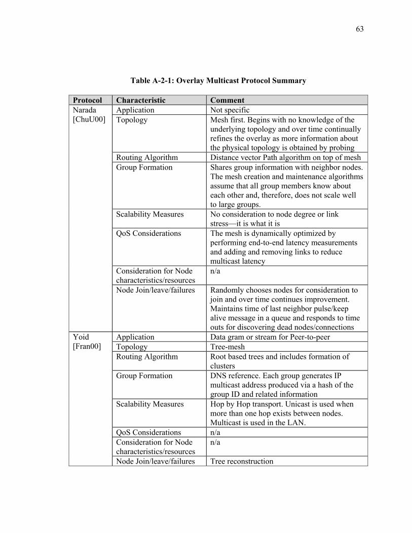
63
Table A-2-1: Overlay Multicast Protocol Summary
Protocol Characteristic Comment Application Not specific Topology Mesh first. Begins with no knowledge of the
underlying topology and over time continually refines the overlay as more information about the physical topology is obtained by probing
Routing Algorithm Distance vector Path algorithm on top of mesh Group Formation Shares group information with neighbor nodes.
The mesh creation and maintenance algorithms assume that all group members know about each other and, therefore, does not scale well to large groups.
Scalability Measures No consideration to node degree or link stress—it is what it is
QoS Considerations The mesh is dynamically optimized by performing end-to-end latency measurements and adding and removing links to reduce multicast latency
Consideration for Node characteristics/resources
n/a
Narada [ChuU00]
Node Join/leave/failures Randomly chooses nodes for consideration to join and over time continues improvement. Maintains time of last neighbor pulse/keep alive message in a queue and responds to time outs for discovering dead nodes/connections
Application Data gram or stream for Peer-to-peer Topology Tree-mesh Routing Algorithm Root based trees and includes formation of
clusters Group Formation DNS reference. Each group generates IP
multicast address produced via a hash of the group ID and related information
Scalability Measures Hop by Hop transport. Unicast is used when more than one hop exists between nodes. Multicast is used in the LAN.
QoS Considerations n/a Consideration for Node characteristics/resources
n/a
Yoid [Fran00]
Node Join/leave/failures Tree reconstruction
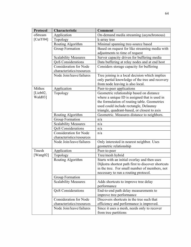
64
Protocol Characteristic Comment Application On-demand media streaming (asynchronous) Topology k-array tree Routing Algorithm Minimal spanning tree-source based Group Formation Based on request for like streaming media with
adjustments to time of request Scalability Measures Server capacity driven for buffering media QoS Considerations Data buffering at relay nodes and at end host Consideration for Node characteristics/resources
Considers storage capacity for buffering
oStream [CuiY04]
Node Join/leave/failures Tree joining is a local decision which implies only partial knowledge of the tree and recovery from node leaving is also local.
Application Peer-to-peer applications Topology Geometric relationship based on distance
where a unique ID is assigned that is used in the formulation of routing table. Geometries used could include rectangle, Delaunay triangle, quadrant-based, or closest to axis
Routing Algorithm Geometric. Measures distance to neighbors. Group Formation n/a Scalability Measures n/a QoS Considerations n/a Consideration for Node characteristics/resources
n/a
Mithos [Lieb02, Wald03]
Node Join/leave/failures Only interested in nearest neighbor. Uses geometric relationship
Application Peer-to-peer Topology Tree/mesh hybrid Routing Algorithm Starts with an initial overlay and then uses
Dijkstra shortest path first to discover shortcuts in the tree. For small number of members, not necessary to run a routing protocol.
Group Formation Scalability Measures Adds shortcuts to improve tree delay
performance QoS Considerations End-to-end path delay measurements to
improve tree performance Consideration for Node characteristics/resources
Discovers shortcuts in the tree such that efficiency and performance is improved.
Tmesh [Wang02]
Node Join/leave/failures Since it uses a mesh, needs only to recover from tree partitions
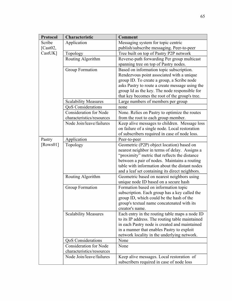
65
Protocol Characteristic Comment Application Messaging system for topic centric
publish/subscribe messaging. Peer-to-peer Topology Tree built on top of Pastry P2P network Routing Algorithm Reverse-path forwarding Per group multicast
spanning tree on top of Pastry nodes. Group Formation Based on information topic subscription.
Rendezvous point associated with a unique group ID. To create a group, a Scribe node asks Pastry to route a create message using the group Id as the key. The node responsible for that key becomes the root of the group's tree.
Scalability Measures Large numbers of members per group QoS Considerations none Consideration for Node characteristics/resources
None. Relies on Pastry to optimize the routes from the root to each group member.
Scribe [Cast02, CastUK]
Node Join/leave/failures Keep alive messages to children. Message loss on failure of a single node. Local restoration of subscribers required in case of node loss.
Application Peer-to-peer Topology Geometric (P2P) object location) based on
nearest neighbor in terms of delay. Assigns a “proximity” metric that reflects the distance between a pair of nodes. Maintains a routing table with information about the distant nodes and a leaf set containing its direct neighbors.
Routing Algorithm Geometric based on nearest neighbors using unique node ID based on a secure hash
Group Formation Formation based on information topic subscription. Each group has a key called the group ID, which could be the hash of the group's textual name concatenated with its creator's name.
Scalability Measures Each entry in the routing table maps a node ID to its IP address. The routing table maintained in each Pastry node is created and maintained in a manner that enables Pastry to exploit network locality in the underlying network.
QoS Considerations None Consideration for Node characteristics/resources
None
Pastry [Rows01]
Node Join/leave/failures Keep alive messages. Local restoration of subscribers required in case of node loss
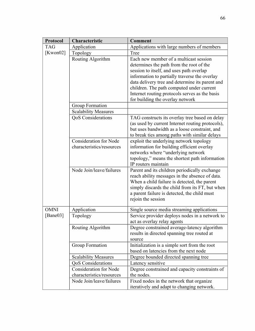
66
Protocol Characteristic Comment Application Applications with large numbers of members Topology Tree Routing Algorithm Each new member of a multicast session
determines the path from the root of the session to itself, and uses path overlap information to partially traverse the overlay data delivery tree and determine its parent and children. The path computed under current Internet routing protocols serves as the basis for building the overlay network
Group Formation Scalability Measures QoS Considerations TAG constructs its overlay tree based on delay
(as used by current Internet routing protocols), but uses bandwidth as a loose constraint, and to break ties among paths with similar delays
Consideration for Node characteristics/resources
exploit the underlying network topology information for building efficient overlay networks where “underlying network topology,” means the shortest path information IP routers maintain
TAG [Kwon02]
Node Join/leave/failures Parent and its children periodically exchange reach ability messages in the absence of data. When a child failure is detected, the parent simply discards the child from its FT, but when a parent failure is detected, the child must rejoin the session
Application Single source media streaming applications Topology Service provider deploys nodes in a network to
act as overlay relay agents Routing Algorithm Degree constrained average-latency algorithm
results in directed spanning tree routed at source
Group Formation Initialization is a simple sort from the root based on latencies from the next node
Scalability Measures Degree bounded directed spanning tree QoS Considerations Latency sensitive Consideration for Node characteristics/resources
Degree constrained and capacity constraints of the nodes.
OMNI [Bane03]
Node Join/leave/failures Fixed nodes in the network that organize iteratively and adapt to changing network.
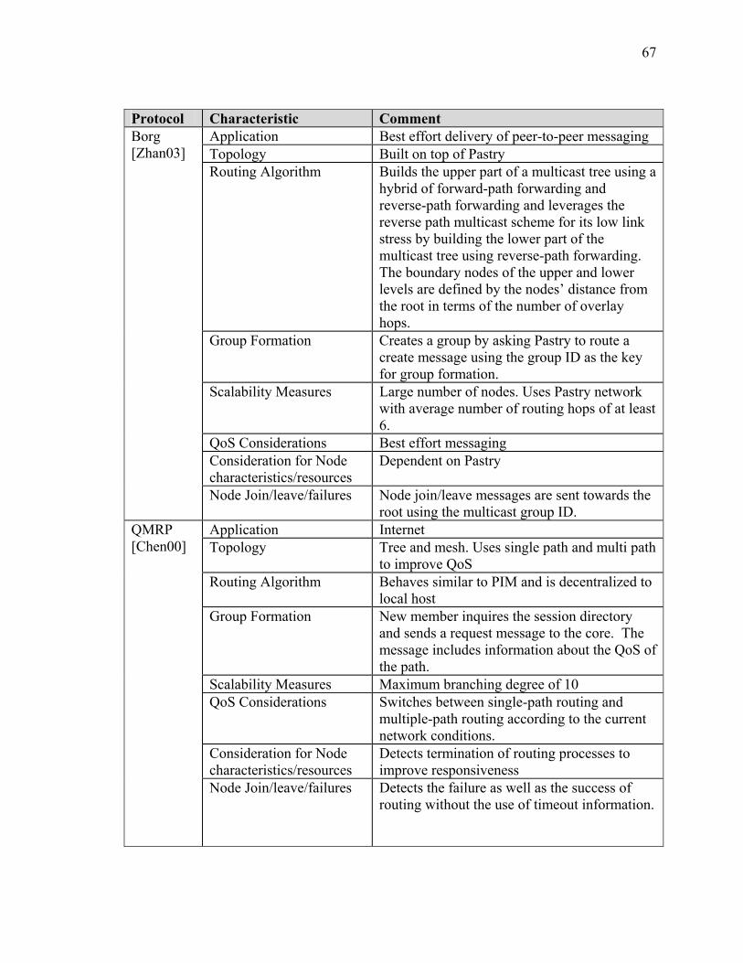
67
Protocol Characteristic Comment Application Best effort delivery of peer-to-peer messaging Topology Built on top of Pastry Routing Algorithm Builds the upper part of a multicast tree using a
hybrid of forward-path forwarding and reverse-path forwarding and leverages the reverse path multicast scheme for its low link stress by building the lower part of the multicast tree using reverse-path forwarding. The boundary nodes of the upper and lower levels are defined by the nodes’ distance from the root in terms of the number of overlay hops.
Group Formation Creates a group by asking Pastry to route a create message using the group ID as the key for group formation.
Scalability Measures Large number of nodes. Uses Pastry network with average number of routing hops of at least 6.
QoS Considerations Best effort messaging Consideration for Node characteristics/resources
Dependent on Pastry
Borg [Zhan03]
Node Join/leave/failures Node join/leave messages are sent towards the root using the multicast group ID.
Application Internet Topology Tree and mesh. Uses single path and multi path
to improve QoS Routing Algorithm Behaves similar to PIM and is decentralized to
local host Group Formation New member inquires the session directory
and sends a request message to the core. The message includes information about the QoS of the path.
Scalability Measures Maximum branching degree of 10 QoS Considerations Switches between single-path routing and
multiple-path routing according to the current network conditions.
Consideration for Node characteristics/resources
Detects termination of routing processes to improve responsiveness
QMRP [Chen00]
Node Join/leave/failures Detects the failure as well as the success of routing without the use of timeout information.
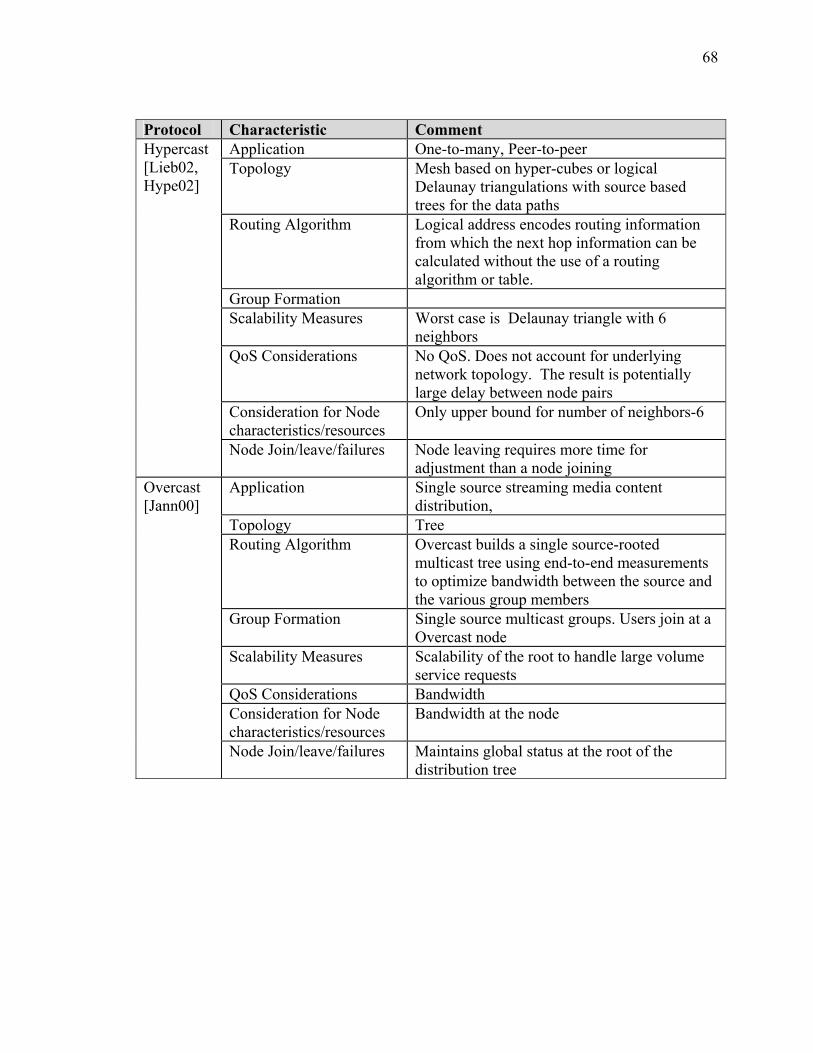
68
Protocol Characteristic Comment Application One-to-many, Peer-to-peer Topology Mesh based on hyper-cubes or logical
Delaunay triangulations with source based trees for the data paths
Routing Algorithm Logical address encodes routing information from which the next hop information can be calculated without the use of a routing algorithm or table.
Group Formation Scalability Measures Worst case is Delaunay triangle with 6
neighbors QoS Considerations No QoS. Does not account for underlying
network topology. The result is potentially large delay between node pairs
Consideration for Node characteristics/resources
Only upper bound for number of neighbors-6
Hypercast [Lieb02, Hype02]
Node Join/leave/failures Node leaving requires more time for adjustment than a node joining
Application Single source streaming media content distribution,
Topology Tree Routing Algorithm Overcast builds a single source-rooted
multicast tree using end-to-end measurements to optimize bandwidth between the source and the various group members
Group Formation Single source multicast groups. Users join at a Overcast node
Scalability Measures Scalability of the root to handle large volume service requests
QoS Considerations Bandwidth Consideration for Node characteristics/resources
Bandwidth at the node
Overcast [Jann00]
Node Join/leave/failures Maintains global status at the root of the distribution tree
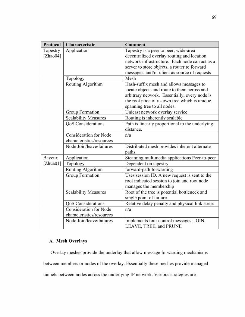
69
Protocol Characteristic Comment
Application Tapestry is a peer to peer, wide-area decentralized overlay routing and location network infrastructure. Each node can act as a server to store objects, a router to forward messages, and/or client as source of requests
Topology Mesh Routing Algorithm Hash-suffix mesh and allows messages to
locate objects and route to them across and arbitrary network. Essentially, every node is the root node of its own tree which is unique spanning tree to all nodes.
Group Formation Unicast network overlay service Scalability Measures Routing is inherently scalable QoS Considerations Path is linearly proportional to the underlying
distance. Consideration for Node characteristics/resources
n/a
Tapestry [Zhao04]
Node Join/leave/failures Distributed mesh provides inherent alternate paths.
Application Steaming multimedia applications Peer-to-peer Topology Dependent on tapestry Routing Algorithm forward-path forwarding Group Formation Uses session ID. A new request is sent to the
root indicated session to join and root node manages the membership
Scalability Measures Root of the tree is potential bottleneck and single point of failure
QoS Considerations Relative delay penalty and physical link stress Consideration for Node characteristics/resources
n/a
Bayeux [Zhua01]
Node Join/leave/failures Implements four control messages: JOIN, LEAVE, TREE, and PRUNE
A. Mesh Overlays
Overlay meshes provide the underlay that allow message forwarding mechanisms
between members or nodes of the overlay. Essentially these meshes provide managed
tunnels between nodes across the underlying IP network. Various strategies are
70
considered in performing establishment of these meshes including use of graphical
shapes that have well known geometric routing principles as well as information about
the underlying network or Internet.
Mithos [Wald03] uses a geometric approach where the network is embedded into a
multi-dimensional space, with every node being assigned a unique coordinate in this
space. The geometric approach greatly simplifies routing as routing is easily enabled with
knowledge of the local grid coordinates. Hypercast [Lieb02, Hype02] also uses this
strategy. This approach uses properties of regular geometric shapes like rectangles,
hypercubes, or Delaunay triangles to greatly simplify routing tables. In fact, in the case of
Hypercast, once the overlay is established, no routing protocol is necessary for the
overlay.
In the rectangular approach, each node is assigned an enclosing axis-parallel
multidimensional rectangle. Message forwarding is easily accomplished by sending to the
rectangle abutting at the point where the vector to the destination intersects with the
current node’s rectangular boundary.
A Delaunay [Lieb02] triangulation uses the special characteristic that for each
circumscribing circle of a triangle formed by three nodes, no other node of the graph is in
the interior of the circle. Each node in a Delaunay triangulation has (x,y) coordinates
which depict a point in the plane. This approach allows each application to derive the
next hop forwarding information without the need of a routing protocol.
While Pastry [Rows01] is a peer-to-peer based protocol, the substrate self-creates a
messaging routing overlay on the Internet that operates in a way that makes the overlay
71
look like a mesh. This is accomplished by each node having a unique 128-bit node ID.
Using this unique ID, Pastry routes a message to the active node that is numerically
closest. This approach provides a level of reliability since the idea is based on an active
node. No further routing protocol is necessary for the local node to make this decision
unlike a tree based approach were tree re-construction is likely required in the case of a
node going inactive. Pastry also uses a metric for closest node such as latency so that
optimum choice for forwarding is always made.
The HyperCast [Hype02] protocol builds logical overlays based on geometric
properties of a logical graph. HyperCast currently implements both the hypercube
[Hype02] and Delaunay [Lieb02] triangles. In each case, applications communicate with
its neighbors in the geometric overlay, both in one-to-many multicast and many-to-one or
anycast. The key advantage to using geometric logical relationships is that once the
overlay is established, there is no further need for a routing protocol. The key
disadvantage of this approach is that the underlying physical network is completely
ignored, which makes it difficult to consider end-to-end latency in performance. Another
disadvantage is that hypercube overlays must be formed sequentially with the result that
for a large set of nodes, it is likely that it will take a long time to construct the overlay
and also complicates departure or joining of a single node. In the case of Delaunay
triangles, overlay construction can be accomplished faster since as they can be built in a
distributed fashion.
The logical hypercube overlay network topology organizes the applications into a
logical n-dimensional hypercube. Each node is identified by a label (e.g., "010"), which
72
indicates the position of the node in the logical hypercube. Message forwarding is easily
accomplished by logical reference to nearest neighbor, hence no need for a routing
protocol once the overlay is established.
Tapestry [Zhao04] is a unicast overlay network that provides the infrastructure for
other multicast protocols like Bayeux [Zhua01]. The Tapestry routing mechanism is
similar to longest prefix routing used in the CIDR IP infrastructure of the Internet
[Rekh93], RFC 1518. The routing mechanism is a hash-prefix system which essentially
results in every destination node being the root of its own tree that is the unique spanning
tree across all nodes. The approach is inherently decentralized. Tapestry includes fault
tolerant mechanisms that provide redundant paths to all destinations. This strategy
effectively routes around failed nodes, in essence providing a mesh type infrastructure.
B. Tree Overlays
oSTREAM [CuiY04] is a tree based overlay that is specifically designed for one-to-
many on-demand media distribution. The approach is to establish a minimum spanning
tree and use media buffering at the host to aid in the distribution of asynchronous service
requests for the same streaming media. While this strategy is not particularly useful for a
many-to-many environment, there are some similarities in forwarding the same
information to asynchronous requests in the web services model. This might apply, for
example, in the case where more static background information such as terrain models or
weather information might be asynchronously requested from group members in a

73
simulation. In these types of data distribution requests, there would be link and server
efficiency advantages to using this approach.
Yoid [Fran00] employs a single shared tree for all members of the group. The links
are unicast multi-router-hop paths. Trees are managed by a concept of child/parent
relationship amongst members of the overlay. A member with no parent is the root
member, and members with no children are leaf members and stub members are always
leaf members. Each member divides the set of all other members into two groups called
parent-side and child-side members. The groups are defined such that parent side
members are all members reachable via the parent and all others are child-side members.
Each member must mange this and understand how to protect from partition and make
decisions on a new parent if the tree is partitioned.
Topology Aware Grouping (TAG) [Kwon02] exploits underlying network topology
information to build efficient overlay tree networks among multicast group members.
TAG uses information about path overlap among members to construct a tree that
reduces the overlay relative delay penalty, and reduces the number of duplicate copies of
a packet on the same link. Each member of a TAG multicast session determines the path
from the root of the session to itself and determines its parent and children. TAG nodes
need only the IP addresses and paths of their parent and children nodes. TAG is unusual
in that it constructs its overlay tree based on delay and considers network capacity to
break ties among paths with similar delays when constructing the overlay. This approach
has merit for consideration as it provides the opportunity to guarantee end-to-end latency
performance for the overlay. TAG does this by taking advantage of the underlying
74
network shortest path topology information maintained in the underlying network IP
routers.
The Overlay Multicast Network Infrastructure (OMNI) [Bane03] is a two-tier
approach to overlay multicast. The lower tier consists of a set of devices or service nodes
that are distributed throughout an underlying network infrastructure like the Internet. The
lower tier provides data distribution services to any host connected to an OMNI node
over a directed spanning tree rooted at the source OMNI node. An end-host subscribes
with a single OMNI node to receive multicast data service. The OMNI nodes organize
themselves into an overlay which forms the multicast data delivery backbone. For the
second layer, the data delivery path from the OMNI nodes to its clients is independent of
the data delivery path used in the overlay backbone. This path can be built using network
layer multicast, application-layer multicast, or a set of unicast paths.
Overcast [Jann00] is a single source multicast overlay designed for on-demand and
live data delivery. The protocol is single source tree based with some added features to
provide reliable delivery to multicast groups. Reliability is provided by using TCP e.g.,
HTTP over port 80.
C. Hybrid Mesh-Tree Overlays
As indicated earlier, there are two basic methods for construction of overlay trees for
data delivery. First, one can construct a tree directly by members selecting their parents
from among group members that they know. The second is to construct a well connected
mesh of the group members and then use standard shortest path tree construction
75
algorithms to establish the minimum distribution spanning tree. Protocols such as Narada
[ChuU00] apply a two step process where in the first step an overlay mesh is constructed
and then a tree is constructed using a shortest path algorithm on the nodes of the mesh.
While the mesh construction can be accomplished in an arbitrary fashion relative to
the underlying infrastructure, there is value in using knowledge of the underlying
structure for building the mesh so as to improve overall performance of the overlay. The
hypercube and Delaunay triangle techniques described above, for example, can easily be
applied to build meshes without regard to underlying infrastructure. The technique might
work well for peer-to-peer information exchange where end-to-end performance
constraints are less stringent.
Narada [ChuU00], however, tries to build the mesh using knowledge of underlying
network performance characteristics. Narada applies a reverse shortest path algorithm in
the second step to establish shortest path minimum spanning trees with each tree rooted at
the source node. Several advantages result from this approach:
• Group management can be accomplished at the mesh level and more easily allows
for the use of a standard group management protocol like IGMP at the local
distribution level.
• Meshes are more resilient than trees; repair and optimization are easier to
accomplish as loop avoidance is not required during this process.
• There are many existing algorithms for construction of shortest path trees on top
of the mesh.
76
Another protocol that uses this general strategy is Tmesh [Wang02], which uses an
algorithm to determine shortcuts in the tree. The idea is to correlate measurable
characteristics with a computed reduction in node-pair latencies attributed to each
shortcut. This information is then used in a heuristic to select a shortcut with the objective
of improving overall latency.
D. Peer-To-Peer Overlays
There is another definition of overlay networking that is normally associated with
information or message exchange at the application layer without using the services of an
intermediary host, such as in a client server application, called peer-to-peer. Peer-to-peer
is typically used to define an end point or application layer exchange of information.
They are not treated here as a separate category, as they apply routing principles similar
to overlays in general, but the relationship requires some explanation as there are many
developments in progress for implementation of self-organizing and decentralized peer-
to-peer overlay networks [Zhan03]. These efforts support new distributed applications
which require information discover and message exchange across a network of loosely
coupled applications.
The point-to-point overlays typically implement distributed hash tables that allow for
location of an object within a bounded number of routing hops. They tend to exploit
proximity in the underlying network topology in locating objects and routing.
Multicasting is built on top of these peer-to-peer overlays. Examples of this strategy
include Borg [Zhan03] and Scribe [Cast02, CastUK] which are built on Pastry [Rows01]
77
and Bayeux [Zhua01] which is built on Tapestry [Zhao04]. Both Pastry and Tapestry
provide unicast routing based on prefix-routing, and use a proximity neighbor selection
mechanism to take advantage of the underlying physical network. Tapestry and Pastry
also provide sensitivity to QoS by constraining the routing distance per overlay hop,
resulting in efficient point-to-point routing between nodes in the overlay mesh.
Scribe uses reverse-path forwarding and Bayeux uses forward-path forwarding. The
reverse-path construction of Scribe causes many short links in the multicast scheme
which provides for lower link stress than Bayeux. Borg uses a hybrid multicast scheme to
take advantage of asymmetry in routing in structured point-to-point networks. Borg
builds the upper part of a multicast tree using a hybrid of forward-path forwarding and
reverse-path forwarding and leverages the reverse-path multicast scheme for its low link
stress by building the lower part of the multicast tree using reverse-path forwarding.
Peer-to-peer overlays networks generally are unpredictable and therefore impact
quality of delivery of messages [Chen00]. Strategies such as message preservation
priority in queues and expiration times are sometimes used to enable some level of QoS.
An example is to discard messages that have reached expiration times, or at least give
priority to those that have not.
IV Summary
The main objective of overlay multicast protocols is to provide a multipoint service
that is independent of underlying network services. This allows unique applications such
as distributed real time applications to be effectively and efficiently deployed across open

78
networks that do not provide a multicast service. This section has provided a summary of
many initiatives designed to provide an overlay multicast service. These initiatives tend
to be driven by unique characteristics of the target application environment. The result
has been multiple strategies to achieve performance objectives for each of the unique
characteristic environments. A similar challenge exits for the unique characteristics of the
real time distributed simulation environment to find a solution to provide efficient
multipoint communications services.
79
SECTION 3 BACKGROUND AND SURVEY OF RELATED ROUTING ALGORITHMS
I Introduction
Applying multicast routing algorithms in routing protocols is about optimizing certain
objective functions to improve overall quality and efficiency of message delivery. Quality
is typically measured in terms of latency and message loss rate. Efficiency is normally
measured in terms of link stress or minimizing the number of times a packet traverses an
individual link in the network.
The routing algorithms solve a shortest path problem, potentially with many
constraints; to build a tree connecting the source(s) and destination group members so
that minimal message flow occurs in the distribution of the message as well as
maintaining optimum latency from source to each destination. The optimal case is that
only a single copy of the message flows on any link in the overlay (link stress), meets
application latency requirements (delay), and offers some level of reliability (minimum
packet loss). Typical resources that are allocated or that must be optimized are link
capacity, host processing capacity, number of links or diameter of the tree, and the degree
or number of connections to other nodes in the overlay. In addition, the algorithm must
lend itself to supporting dynamic overlays where many multicast group members join and
leave in real-time. It is also important to consider the scalability of the algorithm which is
made considerably more difficult in large networks since end systems in large networks
80
typically have limited topological information in which to construct good overlay paths.
The underlying topology is also changing over time with new links joining and others
leaving [Diot97].
The need for modeling and simulation multicast services can be defined as a multicast
flow problem. This multicast flow problem involves sending flow from a source to a set
of destinations or receivers. In this approach, a directed tree rooted at the source and
reaching all receivers is used as the basic unit of flow for the multicast network flow. A
multicast flow is then defined as a collection of flows along directed trees obeying the
capacity constraints for each edge in a path. The general graph problem is normally
defined as a weighted digraph G = (V,E), node set V, edge set E, edge costs or capacities
cij, source s and set of receivers R and includes a set of constraints as outlined above
[Wang00].
If we use Wang’s [Wang00] definition for M to be a multicast group or a subset of the
nodes V that are involved in a group communications, we can then define a multicast
flow as messages originating from a set of source nodes that are to be delivered to the set
M destination nodes. These multicast flows can be one-to-one, one-to-many, or many-to-
many. Our interest is in many-to-many as the most applicable to real time distributed
simulations. The other cases can be described as sub classes of the more general class of
many-to-many. In the many-to-many case, any node can be a sender or receiver, or both.
Section 2 presented the general problem as a flow problem, repeated here for clarity:
Given network G = (N,A), node set N, arc set A, arc capacities cij, source s
and set of receivers R⊆N - {s}, any multicast flow is identified with a
81
collection of directed trees {T1 , T2 ,….,Tl} rooted at s and reaching all
nodes in R and associated flows {x1 , x2 ,….,xl} with constraints:
Σ(1≤k≤l) f(i,j,Tk)*xk ≤ cij ∀ (i,j) ∈ A
f(i,j,Tk) = { 1 If arc (i,j) appears in Tree Tk and 0 Otherwise
The edge cost or capacity cij normally is associated with the expected delay a message
might encounter on an outgoing link. This includes the queuing delay associated with the
interface to the link, the capacity of the interface to the link, transmission time and the
propagation delay along the link to the next node. The underlying routing algorithm
would use the edge cost in an optimization to determine the multicast tree to be used to
connect the source to all group member destinations.
As indicated above, many resources can be considered for allocation in optimizing
the overlay. For real time modeling and simulation, the demand for improved quality of
service over best effort implies consideration for other factors besides link delay in the
construction of distribution trees. The desire is to have a “global” optimization such that
the overall experience of the distributed simulation is consistent for the registered set of
users. This is in contrast to a protocol like Overcast [Jann00] which optimizes network
capacity rather than any consideration of other factors such as end-to-end latency or host
resources.
Early laboratory tests of the XOM Relay (XOMR) prototype indicate the importance
of knowing the resource capacity of the XOMR host. (XOMR refers to the actual
protocol software.) In these laboratory experiments, the host performance in terms of
82
ability to service message interrupts was the limiting factor in performance. (The detailed
results are presented in Section 6.)
If we assume that the access link capacity to the underlying open network or Internet
is not the constraint, then the resource limitation of the host and end-to-end latency across
the overlay are the constraints to be optimized. Studies of the three simulation
experiments described in Section 4 support this assumption.
This appears to be a valid assumption for current simulation environments but is not
necessarily valid for future applications such as tactical military networks, where access
link capacity may be constrained. If we expand the application environment to other real
time applications or extending simulation to operational environments, then the
assumption of no access link constraint may not be valid. An example might be the use of
simulation in a forward battle area of a military operation where network capacity is
likely to be constrained. In this case, consideration to link capacity may become
important as part of the overall optimization.
The traditional approach for management of link capacity constraints is through flow
control. TCP provides this service in current reliable transport. The current XOMR
prototype uses UDP but is not restricted to use of UDP and could be implemented using
TCP. Since UDP provides no direct feedback mechanism for performance of a link, it
then becomes more important for the XOMR to have some capability for link capacity
constraint management to support potential applications in constrained link capacity
environments. Simon [Simo04] proposed using a statistical approach similar to that used
in the ATM protocol as way to predict forward congestion and then to implement
83
appropriate sending rate control at the sending host based on this prediction model. Other
mechanisms such as reserving capacity or simply allowing only sending at a certain
threshold rate could be used for rate control. This threshold could be a simple locally
controlled capability based on known host resources.
Another possible approach implements class queuing at the sender host. In this
approach, two classes of service, for example, might be offered to the application similar
to how ATM provides different classes of service. In this case, lower priority traffic is
discarded when there is projected congestion.
The remainder of this section provides a survey of possible routing algorithms and
reviews them in the context of expected requirements of using multicast routing to
support real time distributed simulations. This is an important differentiator as the
opportunity in overlay multicasting is the ability to acknowledge unique features of the
target environment.
II Algorithms Background
Multicast routing continues to become more important in distributed group
communications and as a result has fostered a great many initiatives in developing new
protocols and supporting routing algorithms. Diot [Diot97] provides a broad survey of
protocols and supporting functions required for distributed group communications. The
basic definitions associated with multicast routing provided in this reference are directly
relevant and provide a very good basis for review of routing algorithms.
84
Reference [Diot97] summarizes the challenges of Internet multicast routing as the
overall need to minimize network load, provide some basic support for reliable
transmission of messages, and include the ability to design optimal routes under different
cost constraints while minimizing the amount of statistical information stored at a router.
These are well stated challenges. Similar challenges apply to overlay routing to support
real time distributed simulation but with some differences in the objective functions.
Both Internet multicast routing and routing in general must avoid loops and have
algorithms that provide for avoidance of traffic load on a link or subnetwork. This is also
important in overlay multicasting, as the resources of the host and possibly the host
access link are critical constraints in the overlay. The overlay assumes that the underlying
Internet is providing optimal service using standard IP routing protocols.
Reliable transmission is aided by having stable routes. In IP layer multicasting this
implies protection from link failures and awareness to minimizing route changes. In an
overlay, failure translates to a node failure (host) either by the host failing or the host
access link to the Internet goes out of service. Note that failure of node can include host
overload or access link congestion. The overlay network then requires an assumption that
the underlying network is stable and manages route changes internally that are invisible
to the overlay.
One characteristic of real time simulations is able to help compensate for periods of
congestion and possibly brief periods of lost messages either in the underlying network or
in the overlay. This characteristic results from the design of these applications, as they
have behavior algorithms that are able to predict the next state of a simulation object
85
without regard to receiving an update message, should the message be lost or not arrive in
a timely manor. [Moen01]. This implies that the overlay performance has some flexibility
in reliability that might not exist in other applications such as streaming video.
Another stated challenge is the need for minimizing state information stored in the
routers of a multicast network [Diot97]. The concern in the overlay approach is not
necessarily memory of the node host, but rather the amount of network traffic generated
to distribute updates to this information in large networks. While available information is
limited regarding how many participants there might be in a community of interest (COI)
for a specific simulation environment, there is likely to be an expected limit on the
number of players that could conceivably interact in a particular real time simulation.
There are application environments, however, where distribution of real time information
updates would be much different, for example an operational military environment.
The primary reason for routing algorithms is to design optimal routes, given a set of
constraints. As discussed above, this normally translates to shortest path routes based on
link or edge costs. There are other factors to consider in the overlay such as the resources
of the host. We have already demonstrated this constraint in early laboratory tests
[Moen04]. Overlay node access link capacity is another example and is complex in that
the overlay host is likely to be sharing this link with other applications.
End-to-end delay is also an important constraint for real time simulations. This
implies the introduction of path latency as a constraint in constructing the overlay. The
real time simulation environment further refines this as a need for global optimization for
latency. The reason for this as that these applications desire responsiveness measured in
86
human time. This means that all players in a COI have some expectation to be interacting
in human time responses. For the players, interacting in different time frames does not
have the same value and results in unresponsive behavior that might no longer be
considered real time. The constraint can be defined as the diameter of the network where
diameter means there is an end-to-end constraint that represents time or latency end-to-
end across the overlay. This could be in terms of hop count if it correlates to time or sum
of the edge costs of a path in terms of edge delay.
In light of these challenges, it is important to recognize that in the end, the routing
algorithm must work with reasonable efficiency and also maintain a simplicity that
provides ability to be managed and maintain stability for the supported applications. The
paragraphs that follow provide an overview of a number of existing algorithms that are in
various states of research and implementation. Each is viewed in the context of the merits
to support real time simulations.
III Survey of Routing Algorithms
The simplest algorithm for multicast is broadcast or flooding the network with the
messages to be distributed. This approach is obviously not at all efficient for large
volume message distribution to large groups of recipients, however is very effective in
local area networks and is the standard today for this application. It is simple and requires
no calculations or algorithms to support message distribution in the local subnet. It is not
effective in large groups of users distributed across many subnetworks.

87
Given the need for communicating with a multicast group and recognizing the need to
optimize a set of resources or constraints, then the problem is to apply a routing algorithm
that builds a multicast tree that optimizes an objective function. There are many proposed
algorithms designed to solve this problem. Wang [Wang00] classifies multicast routing
into 12 distinct definitions of the problem according to link and tree constraints. For
reference, these definitions are quoted here:
“1) A link-constrained problem: A link constraint is imposed to construct feasible
multicast trees (e.g., bandwidth-constrained routing).
2) A multiple-link-constrained problem: Two or more link constraints are imposed to
construct feasible trees (e.g., bandwidth- and buffer-constrained routing).
3) A tree-constrained problem: A tree constraint is imposed to construct feasible
multicast trees (e.g., delay constrained routing).
4) A multiple-tree-constrained problem: Two or more tree constraints are imposed to
construct feasible multicast trees (e.g., delay- and inter receiver- delay-jitter-constrained
routing).
5) A link- and tree-constrained problem: A link constraint and a tree constraint are
imposed to construct feasible multicast trees (e.g., delay and bandwidth-constrained
routing).
6) A link optimization problem: A link optimization function is used to locate an optimal
multicast tree (e.g., maximization of the link bandwidth over on-tree links in a multicast
tree).
88
7) A tree optimization problem: A tree optimization function is used to locate an optimal
multicast tree (e.g., minimization of the total cost of a multicast tree). This is also known
as the Steiner tree problem.
8) A link-constrained link optimization problem: A link constraint is imposed and a link
optimization function is used to locate an optimal multicast tree that fulfills the constraint
(e.g., the bandwidth-constrained buffer optimization problem).
9) A link-constrained tree optimization problem: A link constraint is imposed and a tree
optimization function is used to locate an optimal multicast tree (e.g., the bandwidth-
constrained Steiner tree problem).
10) A tree-constrained link optimization routing problem: A tree constraint and a link
optimization function are used to locate an optimal multicast tree (e.g., the delay-
constrained bandwidth optimization problem).
11) A tree-constrained tree optimization routing problem: A tree constraint and a tree
optimization function are used to locate an optimal multicast tree (e.g., the delay-
constrained Steiner tree problem).
12) A link and tree constrained tree optimization routing problem: Link and tree
constraints and a tree optimization function are used to locate an optimal multicast tree
(e.g., the bandwidth- and delay-constrained tree optimization problem).”
In the early description of the problem statement presented in [Moen03], it was
defined as a classic Steiner problem because the objective is a global optimization of
network resources. The global optimization here is defined as minimizing the total cost of
the resulting multicast tree. By definition, if all the nodes are included in the group

89
membership, then this problem is the same as the minimum spanning tree problem. This
is very a very attractive characteristic, one that should be considered in the architecture of
the overlay protocol. While the Steiner problem remains a good description of the overlay
multicast problem for distributed simulation, its solution is NP-complete [Wang00]. The
same is true for problem definitions 4, 7, 9, 11, and 12 above.
According to Wang [Wang00], problems 1 and 2 are solvable because link constraints
can be removed from the problems that do not meet selection criteria and can then be
solved in polynomial time. Problems 3, 5, and 10 are solvable in polynomial time. This
constrains the remaining possible algorithm approaches to those that consider single
constraints or to use of an algorithm that is heuristic in nature so that at least approximate
solutions can be obtained in polynomial time.
A literature search was conducted for proposed algorithms that would have potential
for implementation in an overlay multicast network supportive of real time distributed
simulation. The search focused on algorithms that were able to support source based
routing and allow for consideration of constraints in addition to edge cost. The reason for
this becomes apparent later in Section 6 which presents performance studies of the
existing prototype multicast protocol that shows the importance of considering host
resources.
Another important factor for consideration in identifying candidate algorithms is the
expected size of the overlay in terms of number of nodes. The current prototype uses
Dijkstra’s [Corm97] shortest path algorithm for routing. It is a source based algorithm
and performs adequately for the prototype overlay networks with small numbers of nodes

90
which have been part of early experimentation in this research, however may not be
adequate for large overlay networks and the current version doesn’t support multiple
constraints. Dijkstra’s algorithm also does not include consideration for other kinds of
constraints, such as host resources without some modification to the algorithm [Boeh02].
A key assumption that is made for the overlay is that the underlying Internet does not
represent a bottleneck in terms of capacity. This means that capacity measures in the
routing protocol are not necessarily required across the Internet and algorithms that
include network capacity considerations would not be required. However, as indicated
earlier, this may not be the case for operational military networks.
The current approach for the overlay is based on the idea that this is a service
provided by a host or a proxy on a Local Area Network that is available to all
applications on the same subnet. The approach also recognizes that this is a service to a
community of interest and therefore offering a host for this service implies a certain
stability or availability of the host over the period of interest of the community of interest.
What this means is that an assumption can be made that the overlay network is
reasonability stable between networked overlay relay hosts. This raises the possibility
that the problem can be simplified further.
Table A-3-1 provides a summary of algorithms that are being studied and evaluated
by a number of researchers for use in overlay multicasting. The first column presents the
name of the algorithm, though in some cases, this represents the name of a protocol as
they are sometimes presented as synonymous. The source reference is also listed with the
algorithm name.
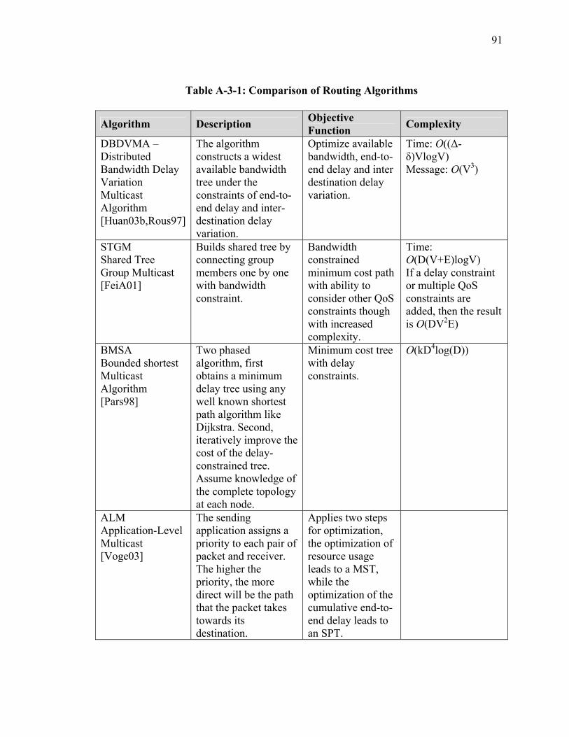
91
Table A-3-1: Comparison of Routing Algorithms
Algorithm Description Objective Function Complexity
DBDVMA –Distributed Bandwidth Delay Variation Multicast Algorithm [Huan03b,Rous97]
The algorithm constructs a widest available bandwidth tree under the constraints of end-to-end delay and inter-destination delay variation.
Optimize available bandwidth, end-to-end delay and inter destination delay variation.
Time: O((∆-δ)VlogV) Message: O(V3)
STGM Shared Tree Group Multicast [FeiA01]
Builds shared tree by connecting group members one by one with bandwidth constraint.
Bandwidth constrained minimum cost path with ability to consider other QoS constraints though with increased complexity.
Time: O(D(V+E)logV) If a delay constraint or multiple QoS constraints are added, then the result is O(DV2E)
BMSA Bounded shortest Multicast Algorithm [Pars98]
Two phased algorithm, first obtains a minimum delay tree using any well known shortest path algorithm like Dijkstra. Second, iteratively improve the cost of the delay-constrained tree. Assume knowledge of the complete topology at each node.
Minimum cost tree with delay constraints.
O(kD4log(D))
ALM Application-Level Multicast [Voge03]
The sending application assigns a priority to each pair of packet and receiver. The higher the priority, the more direct will be the path that the packet takes towards its destination.
Applies two steps for optimization, the optimization of resource usage leads to a MST, while the optimization of the cumulative end-to-end delay leads to an SPT.
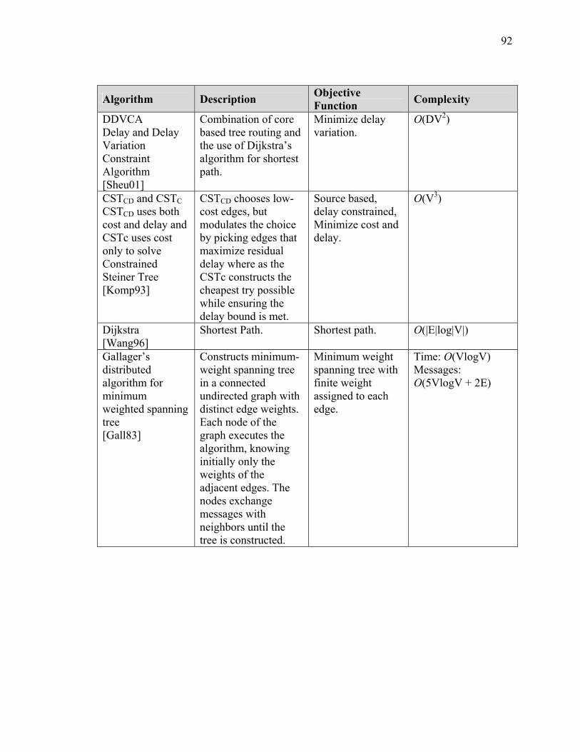
92
Algorithm Description Objective Function Complexity
DDVCA Delay and Delay Variation Constraint Algorithm [Sheu01]
Combination of core based tree routing and the use of Dijkstra’s algorithm for shortest path.
Minimize delay variation.
O(DV2)
CSTCD and CSTC CSTCD uses both cost and delay and CSTc uses cost only to solve Constrained Steiner Tree [Komp93]
CSTCD chooses low-cost edges, but modulates the choice by picking edges that maximize residual delay where as the CSTc constructs the cheapest try possible while ensuring the delay bound is met.
Source based, delay constrained, Minimize cost and delay.
O(V3)
Dijkstra [Wang96]
Shortest Path. Shortest path. O(|E|log|V|)
Gallager’s distributed algorithm for minimum weighted spanning tree [Gall83]
Constructs minimum-weight spanning tree in a connected undirected graph with distinct edge weights. Each node of the graph executes the algorithm, knowing initially only the weights of the adjacent edges. The nodes exchange messages with neighbors until the tree is constructed.
Minimum weight spanning tree with finite weight assigned to each edge.
Time: O(VlogV) Messages: O(5VlogV + 2E)
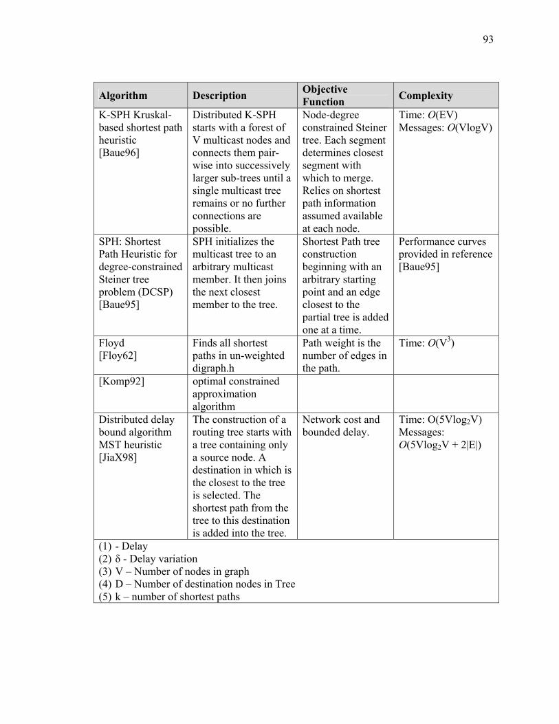
93
Algorithm Description Objective Function Complexity
K-SPH Kruskal-based shortest path heuristic [Baue96]
Distributed K-SPH starts with a forest of V multicast nodes and connects them pair-wise into successively larger sub-trees until a single multicast tree remains or no further connections are possible.
Node-degree constrained Steiner tree. Each segment determines closest segment with which to merge. Relies on shortest path information assumed available at each node.
Time: O(EV) Messages: O(VlogV)
SPH: Shortest Path Heuristic for degree-constrained Steiner tree problem (DCSP) [Baue95]
SPH initializes the multicast tree to an arbitrary multicast member. It then joins the next closest member to the tree.
Shortest Path tree construction beginning with an arbitrary starting point and an edge closest to the partial tree is added one at a time.
Performance curves provided in reference [Baue95]
Floyd [Floy62]
Finds all shortest paths in un-weighted digraph.h
Path weight is the number of edges in the path.
Time: O(V3)
[Komp92] optimal constrained approximation algorithm
Distributed delay bound algorithm MST heuristic [JiaX98]
The construction of a routing tree starts with a tree containing only a source node. A destination in which is the closest to the tree is selected. The shortest path from the tree to this destination is added into the tree.
Network cost and bounded delay.
Time: O(5Vlog2V) Messages: O(5Vlog2V + 2|E|)
(1) - Delay (2) δ - Delay variation (3) V – Number of nodes in graph (4) D – Number of destination nodes in Tree (5) k – number of shortest paths

94
IV Summary
Algorithms for constructing multicast trees seek to optimize the average of the
minimum path delays from the source to each of the destinations and minimizing the cost
of the tree where the tree cost is the sum of the cost of the edges of the tree. In the initial
phase of this research, the problem definition used was the least cost tree approach which
is defined as the Steiner tree problem. Unfortunately, the Steiner problem is NP-
complete.
This Section presented a summary of heuristics and approaches for algorithms to
approximate solutions to the problem. At one end of the spectrum complexity is the NP-
complete Steiner problem and the other flooding a network with messages though
obviously not very efficient in terms of link utilization. The ideal is to have an efficient
algorithm that results in a multicast tree that spans the multicast group members that
minimizes cost functions and minimizes the amount of information needed at each node.
95
SECTION 4 CHARACTERIZATION OF REAL TIME SIMULATION OFFERED MESSAGE LOAD
I Introduction
This section presents results from studies of three real time simulation environments.
The propose of the studies was to gain an understanding of message flow generated by
real time simulations. The primary objective was to develop a characterization or traffic
model of the message flow that would assist in developing an Architecture for the XOM
and result in the development of an appropriate analytical model for real time simulation
message flow. In addition, the characterization of live message flows served to help
validate the source traffic generator software module that was written to assist measuring
the performance of the XOM prototype.
II Summary of Characterization Approach
The overall strategy for characterizing the message flow in a simulation environment
was to instrument live simulation experiments. The OPNET modeling simulation
software [OPNE05] tool set was used to aid in data capture and analysis. Multiple data
samples were obtained in each of three simulation experiments. These experiments
included:
• Wide area network consisting of 2 nodes distributed across the Internet using the
XOMR prototype with each node running a Naval Post Graduate School
96
simulation of a maneuvering sea vessel. This experiment allowed for
measurement of message flow for a single federate (object).
• Single simulation running on notebook computer as the host. This simulation was
an Army ground operations maneuver to contact simulation where real-time was
actual operations maneuver time or the same as wall clock time. This experiment
allowed for instrumentation of an aggregate message flow in a controlled
laboratory environment.
• Wide area network consisting of 3 nodes distributed across the Defense Research
and Engineering Network (DREN). There were 211 Federates distributed across
the network running an urban warfare simulation. This experiment allowed for the
study of large volume message flow across an open network.
While all three where real-time simulation environments, there were significant
differences in the characteristics among them which proved to be of great value in the
overall understanding of the message flow in distributed real-time simulations. Two of
the experiments offered unique opportunities as they were across open networks,
therefore affording an opportunity to gather data in an environment where the XOM is
expected to operate.
The one experiment that was conducted in the laboratory allowed for behavior
analysis independent of any network layer traffic loading. This measurement experiment
therefore offered the opportunity to view pure simulation generated traffic load, unlike
the other experiments. This was of considerably benefit in defining an analytical
approach.
97
Capturing performance information of networked simulations depends on complex
interactions between the application, the services provided by the operating system of the
Host, and the network layer services. Data capture must result in ability to provide
detailed, quantitative understanding of these interactions across different network
segments. The OPNET module called Application Characterization Environment (ACE)
[OPNE05] was used to perform this data capture and analysis. The George Mason
University C3I Center NETLAB was provided a license to use this product under the
OPNET university research program specifically for this project.
ACE provides all the necessary capabilities to collect and analysis application
message data across multiple segment network environments. ACE enables the capture,
filter and the synchronization of multiple capture files. The capture files can be viewed
individually or merged in order to provide an integrated view of message flow between
elements of the environment being studied. The results are presented in graphical from
and can present the end-to-end view of individual message flows. The capture files also
can be exported to a text file where other approaches to analysis can be applied. All of
these approaches were employed in capturing data and performing analysis of the three
simulation experiments.
In order to perform a capture session, capture agents are installed on the targeted
hosts of interest. The OPNET ACE central capture manager is installed on a central
server that has network access to all the capture agents. From this central control module,
all capture activities are controlled such as turning on all agents and then recovering data
captured by each agent. This allowed for fully synchronized capture files.
98
Using ACE allowed visualization of application behavior at the individual transaction
level which enabled graphical visualization and analytical representation of the behavior.
The visualization is presented in a time synchronized, end-to-end view across a multi-tier
network.
III Analysis of Naval Vessel Simulation across Open Network using Web Services and XOM Prototype
The objective in the first experiment was to understand offered network traffic load
characteristics in an environment where multicast was employed. The sites involved were
two academic XMSF laboratories: Old Dominion University (ODU) Virginia Modeling,
Analysis and Simulation Center (VMASC), and GMU C3I Center. The RT-DVS
workload consisted of the HLA Federation supported by the Pitch pRTI 1516, which is
multicast-capable, and the Web Service Interest Management (WSIM) prototype as
described in [Mors04]. The WSIM was used for a Web-service based viewer/controller
for integrating and distributed simulation object update information from the source
simulation applications to the simulation viewer clients at the remote locations. Simulated
objects were naval vessels from the NPS SAVAGE library and visualized on a 3D viewer
from NPSNET (http://www.npsnet.org). The simulation demonstrated no difficulty
sustaining synchronized steaming-in-circles behavior with ship models running at ODU
and GMU. The data rates involved were low: less than ten messages per second per site.
Figure A-4-1 presents the physical relationship for the sample network. The VMASC
location is at Old Domain University Virginia Modeling Analysis and Simulation Center
located in Suffolk, Virginia. The GMU C3I location is at George Mason University
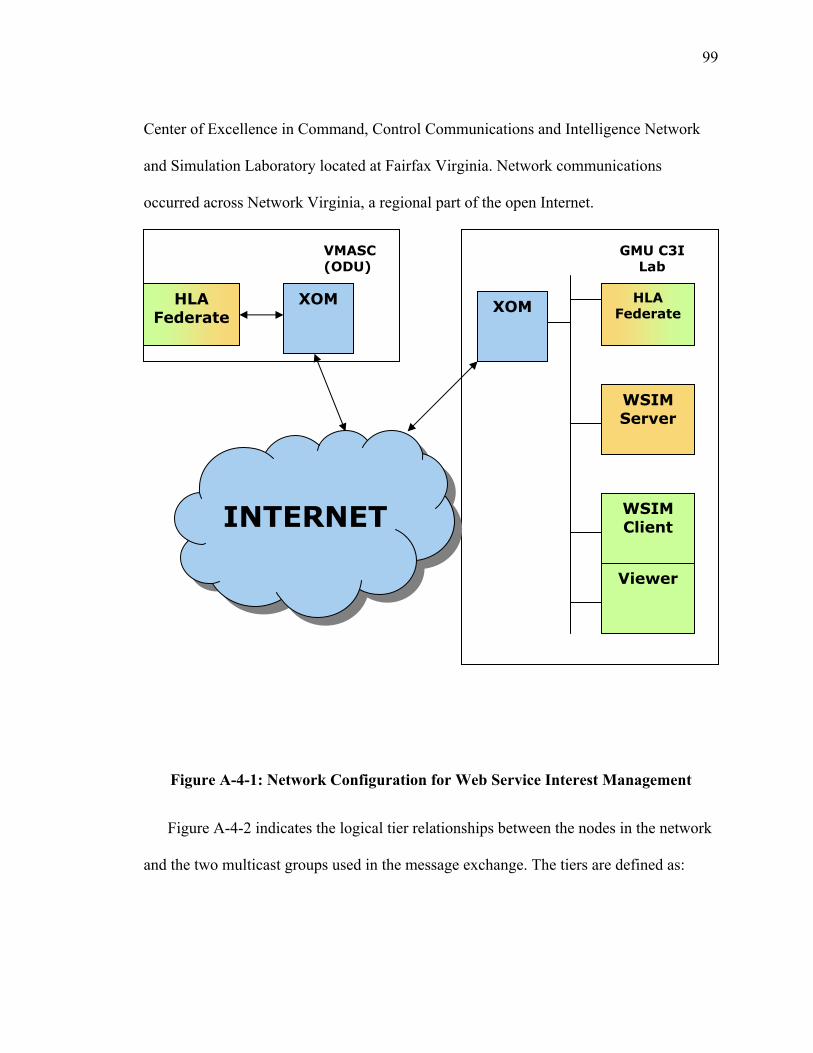
99
Center of Excellence in Command, Control Communications and Intelligence Network
and Simulation Laboratory located at Fairfax Virginia. Network communications
occurred across Network Virginia, a regional part of the open Internet.
Figure A-4-1: Network Configuration for Web Service Interest Management
Figure A-4-2 indicates the logical tier relationships between the nodes in the network
and the two multicast groups used in the message exchange. The tiers are defined as:
HLA Federate
VMASC (ODU)
WSIM Client
Viewer
WSIM Server
XOM HLA Federate
GMU C3I Lab
XOM
INTERNET
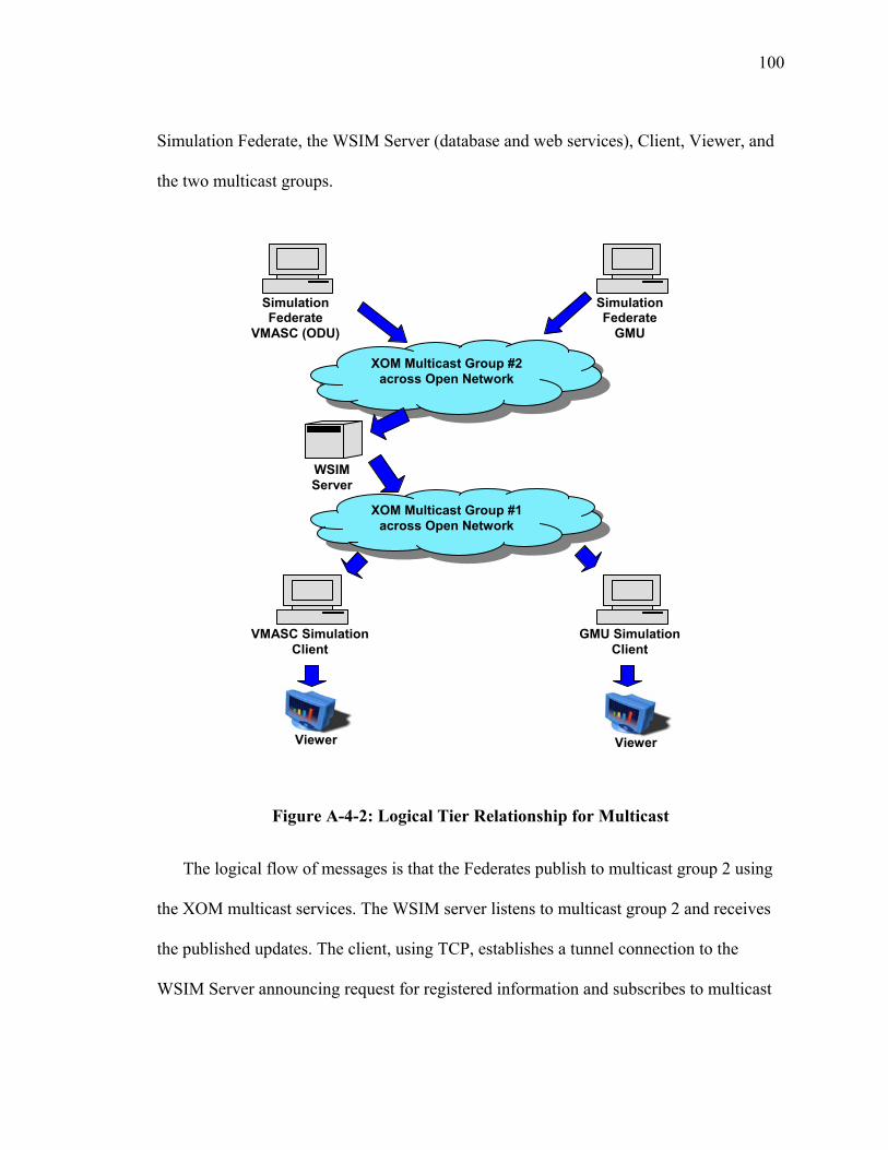
100
Simulation Federate, the WSIM Server (database and web services), Client, Viewer, and
the two multicast groups.
Figure A-4-2: Logical Tier Relationship for Multicast
The logical flow of messages is that the Federates publish to multicast group 2 using
the XOM multicast services. The WSIM server listens to multicast group 2 and receives
the published updates. The client, using TCP, establishes a tunnel connection to the
WSIM Server announcing request for registered information and subscribes to multicast
Simulation Federate
GMU
WSIM Server
XOM Multicast Group #2 across Open Network
Simulation Federate
VMASC (ODU)
VMASC SimulationClient
GMU Simulation Client
Viewer Viewer
XOM Multicast Group #1 across Open Network
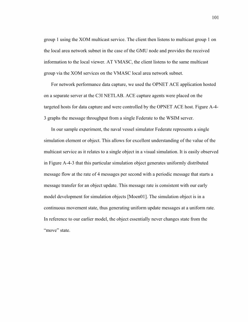
101
group 1 using the XOM multicast service. The client then listens to multicast group 1 on
the local area network subnet in the case of the GMU node and provides the received
information to the local viewer. AT VMASC, the client listens to the same multicast
group via the XOM services on the VMASC local area network subnet.
For network performance data capture, we used the OPNET ACE application hosted
on a separate server at the C3I NETLAB. ACE capture agents were placed on the
targeted hosts for data capture and were controlled by the OPNET ACE host. Figure A-4-
3 graphs the message throughput from a single Federate to the WSIM server.
In our sample experiment, the naval vessel simulator Federate represents a single
simulation element or object. This allows for excellent understanding of the value of the
multicast service as it relates to a single object in a visual simulation. It is easily observed
in Figure A-4-3 that this particular simulation object generates uniformly distributed
message flow at the rate of 4 messages per second with a periodic message that starts a
message transfer for an object update. This message rate is consistent with our early
model development for simulation objects [Moen01]. The simulation object is in a
continuous movement state, thus generating uniform update messages at a uniform rate.
In reference to our earlier model, the object essentially never changes state from the
“move” state.
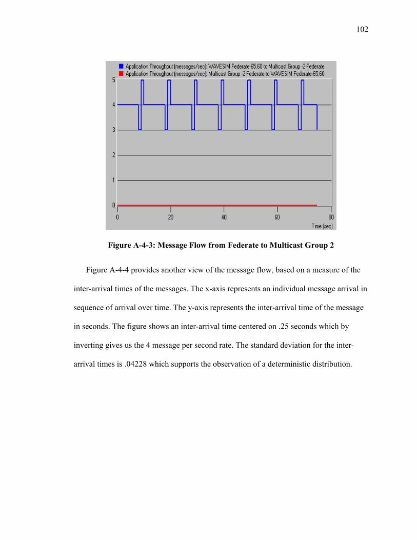
102
Figure A-4-3: Message Flow from Federate to Multicast Group 2
Figure A-4-4 provides another view of the message flow, based on a measure of the
inter-arrival times of the messages. The x-axis represents an individual message arrival in
sequence of arrival over time. The y-axis represents the inter-arrival time of the message
in seconds. The figure shows an inter-arrival time centered on .25 seconds which by
inverting gives us the 4 message per second rate. The standard deviation for the inter-
arrival times is .04228 which supports the observation of a deterministic distribution.
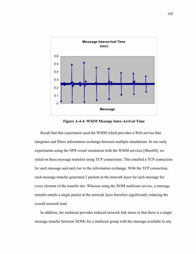
103
Figure A-4-4: WSIM Message Inter-Arrival Time
Recall that this experiment used the WSIM which provides a Web service that
integrates and filters information exchange between multiple simulations. In our early
experiments using the NPS vessel simulation with the WSIM services [Mors04], we
relied on these message transfers using TCP connections. This entailed a TCP connection
for each message and each tier in the information exchange. With the TCP connection,
each message transfer generated 2 packets at the network layer for each message for
every element of the transfer tier. Whereas using the XOM multicast service, a message
transfer entails a single packet at the network layer therefore significantly reducing the
overall network load.
In addition, the multicast provides reduced network link stress in that there is a single
message transfer between XOMs for a multicast group with the message available to any
Message Interarrival Time(sec)
0
0.1
0.2
0.3
0.4
0.5
0.6
Message
104
user on that local subnet. With multiple sites, the advantages of multicast would have
been even more pronounced.
We also simultaneously captured message flow data from the WSIM server to
Multicast group 1, the integrated message flow group the client viewers received. This
message flow integrated the simulation update messages from each of the single vessel
simulations into an integrated view of all the vessels for the client viewer. The viewer
then displayed all the vessels as an integrated simulation visualization even though the
source data where separate single vessel simulations. The results of this capture are
indicated in Figure A-4-5. Here we observed a slightly different message flow pattern,
one that reflects an ON/OFF pattern where OFF implies a lower transmission rate not
necessarily zero. Notice that the periods, or length of time that messages are in the OFF
or ON state appear to be vary slightly over time. By inspecting the raw data, the ON
period represents the transmission of 2 or 3 messages at a deterministic high rate
averaging 8 messages per second with a periodic message transfer at a higher rate
followed by one at a low rate.
The pattern is similar to the Federate uniform rate but periodically has these minor
rate changes. One possibility for this pattern is the random arrival of the second Federate
message relative to the first as a result of wide are network delay and the effect of
processing delay associated with the arrival before the WSIM aggregation message is
forwarded to the multicast group.
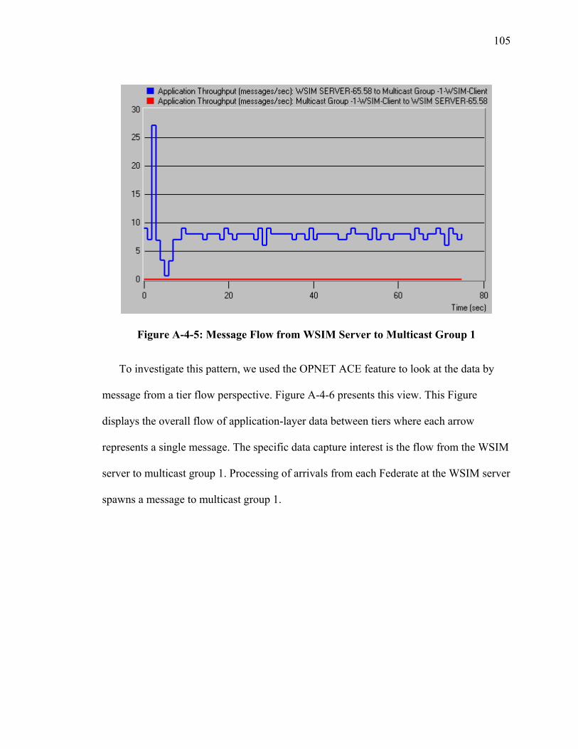
105
Figure A-4-5: Message Flow from WSIM Server to Multicast Group 1
To investigate this pattern, we used the OPNET ACE feature to look at the data by
message from a tier flow perspective. Figure A-4-6 presents this view. This Figure
displays the overall flow of application-layer data between tiers where each arrow
represents a single message. The specific data capture interest is the flow from the WSIM
server to multicast group 1. Processing of arrivals from each Federate at the WSIM server
spawns a message to multicast group 1.
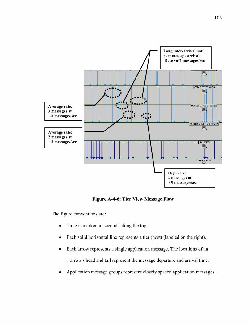
106
Figure A-4-6: Tier View Message Flow
The figure conventions are:
• Time is marked in seconds along the top.
• Each solid horizontal line represents a tier (host) (labeled on the right).
• Each arrow represents a single application message. The locations of an
arrow's head and tail represent the message departure and arrival time.
• Application message groups represent closely spaced application messages.
Average rate: 3 messages at ~8 messages/sec
Long inter-arrival until next message arrival: Rate ~6-7 messages/sec
High rate: 2 messages at ~9 messages/sec
Average rate: 2 messages at ~8 messages/sec
107
• Dependencies indicate network or application delay. A V-shaped line beneath
a tier indicates delay between two messages at that tier.
Another observation is that the message flow rate is never zero for any extended
period of time which supports the idea of ON/OFF pattern implying high and low rates of
message arrival. This observation is an important consideration as we develop a class of
service (priority) capability for the XOM. A continuous message flow rate in a priority
queuing system implies that the possibility exists that a lower priority arrival will never
receive service unless a form of weighted fair queuing is implemented.
These observations also impact global optimization of the overlay resources such as
the network access capacity for each of the XOMRs, link capacities, and number of
intermediate XOMRs in an overlay. This experiment also demonstrated the use of
multicasting as a mechanism to improve efficiency in the distribution of integrated
simulation information across an open network.
IV Ops Simulation
The second simulation experiment was a real-time combat unit operations maneuver
simulation consisting of a background static terrain map overlay and approximately 30
mobile/active objects. The general description of the simulation is a friendly force
combat unit maneuvering to engage an enemy force deployed in defensive positions.
Each object represented a mobile weapons system in the case of the friendly forces and a
defensive position with a weapons system in the case of the enemy forces. Real time in
this simulation is defined as actual operations clock time. This requires many hours of
108
real clock time to completely play out the operations scenario, therefore, the total
scenario was not played to completion but only through initial deployment of friendly
forces upon first contact with the enemy forces.
The data capture was accomplished by running the simulation on a notebook
computer with a crossover cable connection to the ACE central host. There was
essentially no network in the loop. This is observed by the simple message flow diagram
in Figure A-4-7. The diagram indicates message flow in the direction of the arrow with
the total number of messages indicated by the arrow call-out (18359 messages outbound
from the OPS-SIM Host and 0 messages in return). Twelve Data sample collections were
made, each approximately 200 seconds of real clock time. Results from only a single
representative sample of a data capture are presented here. There were no observed
significant differences in the separate data capture files.
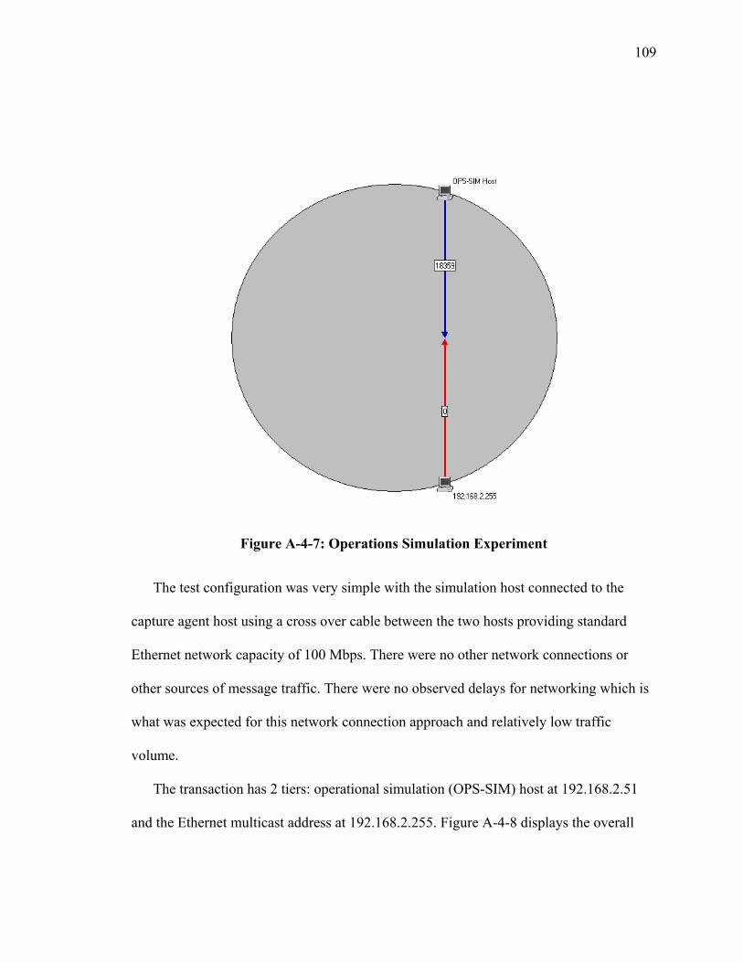
109
Figure A-4-7: Operations Simulation Experiment
The test configuration was very simple with the simulation host connected to the
capture agent host using a cross over cable between the two hosts providing standard
Ethernet network capacity of 100 Mbps. There were no other network connections or
other sources of message traffic. There were no observed delays for networking which is
what was expected for this network connection approach and relatively low traffic
volume.
The transaction has 2 tiers: operational simulation (OPS-SIM) host at 192.168.2.51
and the Ethernet multicast address at 192.168.2.255. Figure A-4-8 displays the overall
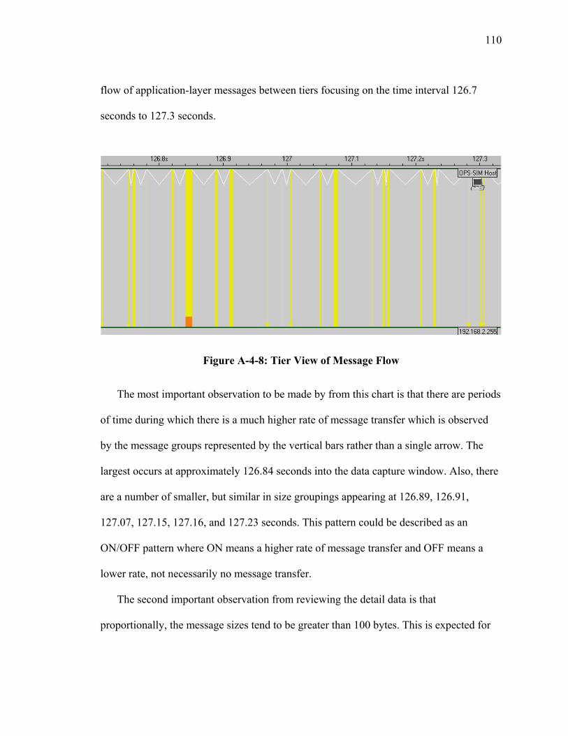
110
flow of application-layer messages between tiers focusing on the time interval 126.7
seconds to 127.3 seconds.
Figure A-4-8: Tier View of Message Flow
The most important observation to be made by from this chart is that there are periods
of time during which there is a much higher rate of message transfer which is observed
by the message groups represented by the vertical bars rather than a single arrow. The
largest occurs at approximately 126.84 seconds into the data capture window. Also, there
are a number of smaller, but similar in size groupings appearing at 126.89, 126.91,
127.07, 127.15, 127.16, and 127.23 seconds. This pattern could be described as an
ON/OFF pattern where ON means a higher rate of message transfer and OFF means a
lower rate, not necessarily no message transfer.
The second important observation from reviewing the detail data is that
proportionally, the message sizes tend to be greater than 100 bytes. This is expected for
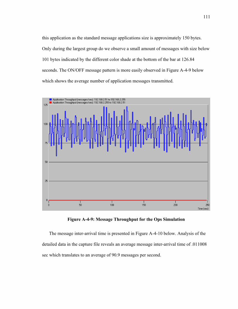
111
this application as the standard message applications size is approximately 150 bytes.
Only during the largest group do we observe a small amount of messages with size below
101 bytes indicated by the different color shade at the bottom of the bar at 126.84
seconds. The ON/OFF message pattern is more easily observed in Figure A-4-9 below
which shows the average number of application messages transmitted.
Figure A-4-9: Message Throughput for the Ops Simulation
The message inter-arrival time is presented in Figure A-4-10 below. Analysis of the
detailed data in the capture file reveals an average message inter-arrival time of .011008
sec which translates to an average of 90.9 messages per second.
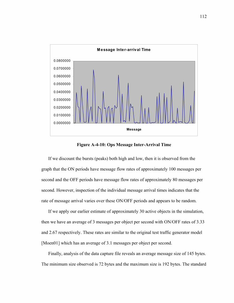
112
Figure A-4-10: Ops Message Inter-Arrival Time
If we discount the bursts (peaks) both high and low, then it is observed from the
graph that the ON periods have message flow rates of approximately 100 messages per
second and the OFF periods have message flow rates of approximately 80 messages per
second. However, inspection of the individual message arrival times indicates that the
rate of message arrival varies over these ON/OFF periods and appears to be random.
If we apply our earlier estimate of approximately 30 active objects in the simulation,
then we have an average of 3 messages per object per second with ON/OFF rates of 3.33
and 2.67 respectively. These rates are similar to the original test traffic generator model
[Moen01] which has an average of 3.1 messages per object per second.
Finally, analysis of the data capture file reveals an average message size of 145 bytes.
The minimum size observed is 72 bytes and the maximum size is 192 bytes. The standard
M essage Inter-arrival Time
0.0000000
0.0100000
0.0200000
0.0300000
0.0400000
0.0500000
0.0600000
0.0700000
0.0800000
Message
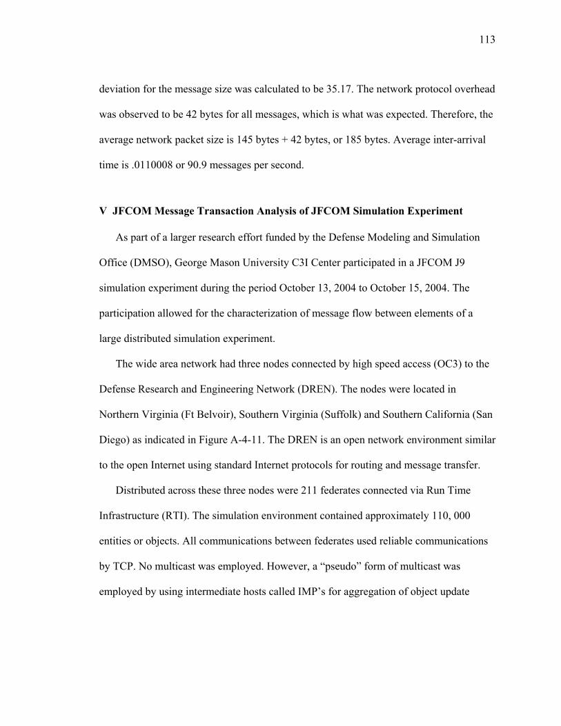
113
deviation for the message size was calculated to be 35.17. The network protocol overhead
was observed to be 42 bytes for all messages, which is what was expected. Therefore, the
average network packet size is 145 bytes + 42 bytes, or 185 bytes. Average inter-arrival
time is .0110008 or 90.9 messages per second.
V JFCOM Message Transaction Analysis of JFCOM Simulation Experiment
As part of a larger research effort funded by the Defense Modeling and Simulation
Office (DMSO), George Mason University C3I Center participated in a JFCOM J9
simulation experiment during the period October 13, 2004 to October 15, 2004. The
participation allowed for the characterization of message flow between elements of a
large distributed simulation experiment.
The wide area network had three nodes connected by high speed access (OC3) to the
Defense Research and Engineering Network (DREN). The nodes were located in
Northern Virginia (Ft Belvoir), Southern Virginia (Suffolk) and Southern California (San
Diego) as indicated in Figure A-4-11. The DREN is an open network environment similar
to the open Internet using standard Internet protocols for routing and message transfer.
Distributed across these three nodes were 211 federates connected via Run Time
Infrastructure (RTI). The simulation environment contained approximately 110, 000
entities or objects. All communications between federates used reliable communications
by TCP. No multicast was employed. However, a “pseudo” form of multicast was
employed by using intermediate hosts called IMP’s for aggregation of object update
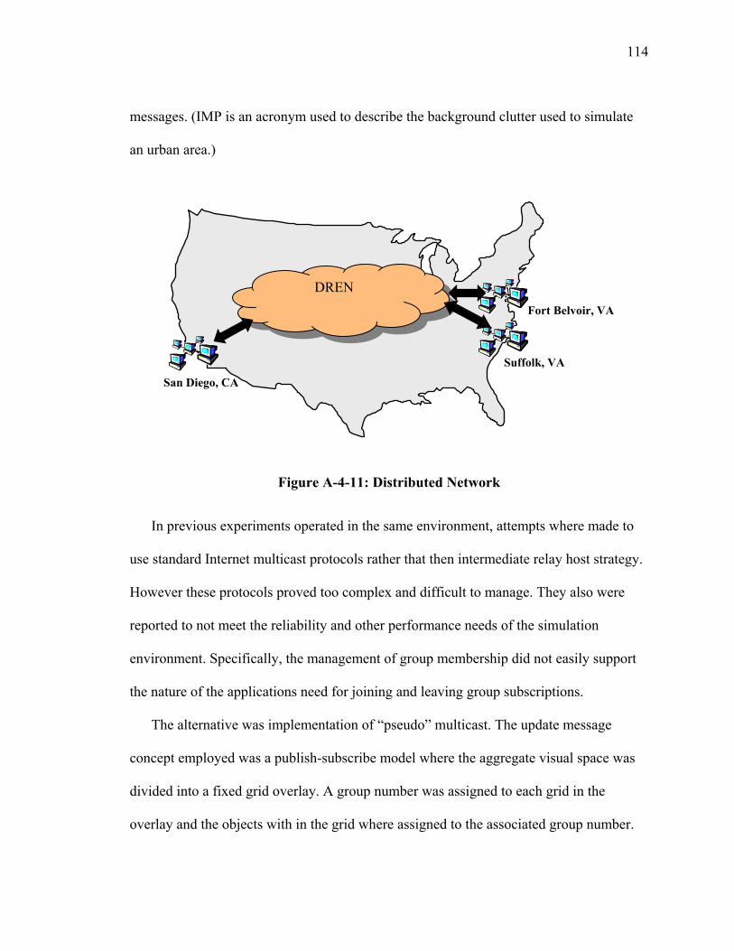
114
messages. (IMP is an acronym used to describe the background clutter used to simulate
an urban area.)
Figure A-4-11: Distributed Network
In previous experiments operated in the same environment, attempts where made to
use standard Internet multicast protocols rather that then intermediate relay host strategy.
However these protocols proved too complex and difficult to manage. They also were
reported to not meet the reliability and other performance needs of the simulation
environment. Specifically, the management of group membership did not easily support
the nature of the applications need for joining and leaving group subscriptions.
The alternative was implementation of “pseudo” multicast. The update message
concept employed was a publish-subscribe model where the aggregate visual space was
divided into a fixed grid overlay. A group number was assigned to each grid in the
overlay and the objects with in the grid where assigned to the associated group number.
DREN
San Diego, CA
Suffolk, VA
Fort Belvoir, VA
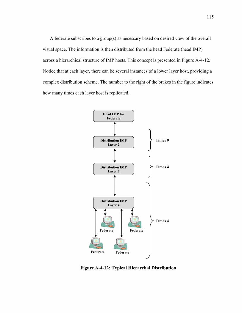
115
A federate subscribes to a group(s) as necessary based on desired view of the overall
visual space. The information is then distributed from the head Federate (head IMP)
across a hierarchical structure of IMP hosts. This concept is presented in Figure A-4-12.
Notice that at each layer, there can be several instances of a lower layer host, providing a
complex distribution scheme. The number to the right of the brakes in the figure indicates
how many times each layer host is replicated.
Figure A-4-12: Typical Hierarchal Distribution
Head IMP for Federate
Distribution IMP Layer 2
Distribution IMP Layer 3
Distribution IMP Layer 4
Federate
Federate Federate
Federate
Times 4
Times 4
Times 9
116
The IMPs in the structure are responsible for store and forward of element message
updates based on group subscriptions of associated Federates. The service provided by
this approach makes no assumptions or guarantees about end-to-end latency for the
delivery of messages. In the case of this experiment, the users accepted the inherent delay
and learned to adjust their interactive response to the delay during the course of running a
real-time operational simulation. In other words, the users accepted the response times of
the longer delays.
Multiple traces of date where collected over a two day period of the experiment. The
following data summary is based on information from one trace of length 8.6 seconds
collected at a Layer 4 IMP labeled Blue IMP-163. The Figure A-4-13 below presents a
tier view of the studied trace. Notice the source message flow is from a Layer 3 IMP
labeled Blue IMP-162. The numbers in the rectangular boxes indicated the total number
of messages sent during the collection period with the arrow heads indicating flow
direction.
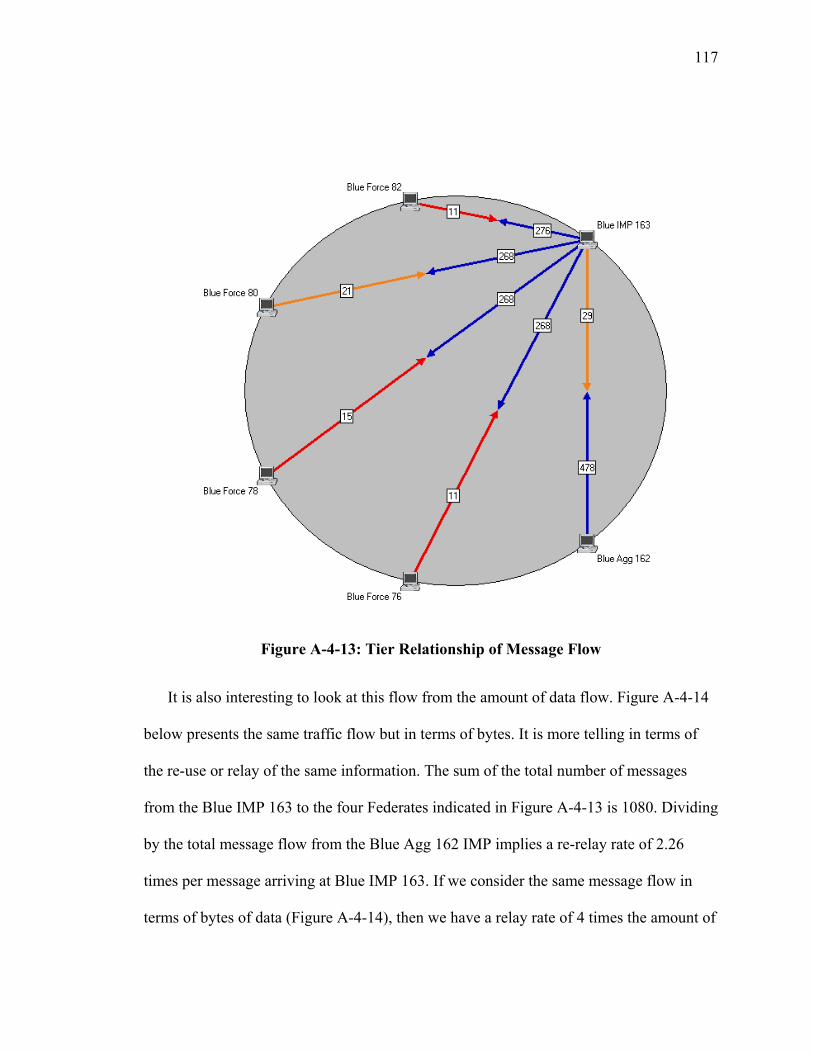
117
Figure A-4-13: Tier Relationship of Message Flow
It is also interesting to look at this flow from the amount of data flow. Figure A-4-14
below presents the same traffic flow but in terms of bytes. It is more telling in terms of
the re-use or relay of the same information. The sum of the total number of messages
from the Blue IMP 163 to the four Federates indicated in Figure A-4-13 is 1080. Dividing
by the total message flow from the Blue Agg 162 IMP implies a re-relay rate of 2.26
times per message arriving at Blue IMP 163. If we consider the same message flow in
terms of bytes of data (Figure A-4-14), then we have a relay rate of 4 times the amount of
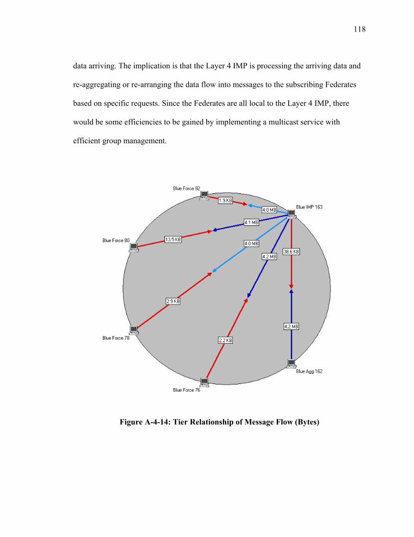
118
data arriving. The implication is that the Layer 4 IMP is processing the arriving data and
re-aggregating or re-arranging the data flow into messages to the subscribing Federates
based on specific requests. Since the Federates are all local to the Layer 4 IMP, there
would be some efficiencies to be gained by implementing a multicast service with
efficient group management.
Figure A-4-14: Tier Relationship of Message Flow (Bytes)
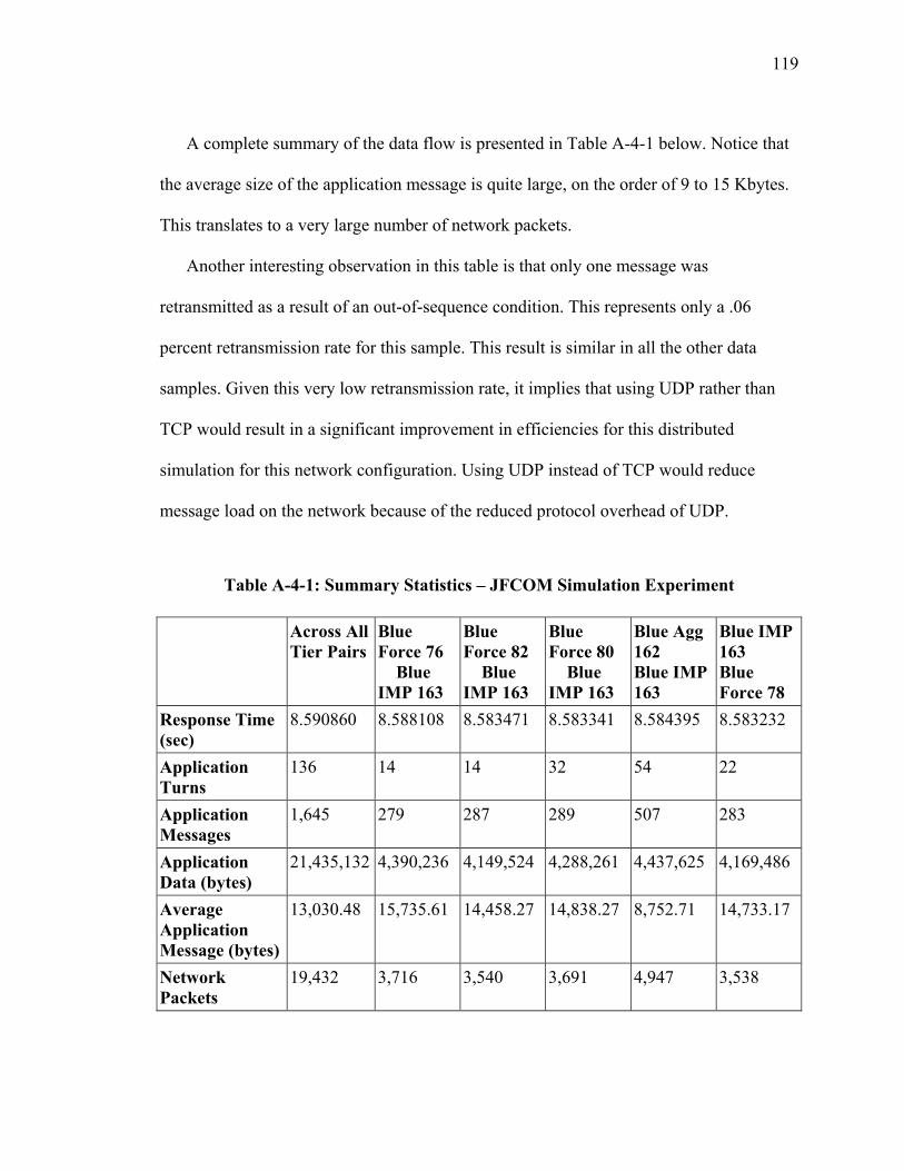
119
A complete summary of the data flow is presented in Table A-4-1 below. Notice that
the average size of the application message is quite large, on the order of 9 to 15 Kbytes.
This translates to a very large number of network packets.
Another interesting observation in this table is that only one message was
retransmitted as a result of an out-of-sequence condition. This represents only a .06
percent retransmission rate for this sample. This result is similar in all the other data
samples. Given this very low retransmission rate, it implies that using UDP rather than
TCP would result in a significant improvement in efficiencies for this distributed
simulation for this network configuration. Using UDP instead of TCP would reduce
message load on the network because of the reduced protocol overhead of UDP.
Table A-4-1: Summary Statistics – JFCOM Simulation Experiment
Across All Tier Pairs
Blue Force 76 � Blue IMP 163
Blue Force 82 � Blue IMP 163
Blue Force 80 � Blue IMP 163
Blue Agg 162 � Blue IMP 163
Blue IMP 163 � Blue Force 78
Response Time (sec)
8.590860 8.588108 8.583471 8.583341 8.584395 8.583232
Application Turns
136 14 14 32 54 22
Application Messages
1,645 279 287 289 507 283
Application Data (bytes)
21,435,132 4,390,236 4,149,524 4,288,261 4,437,625 4,169,486
Average Application Message (bytes)
13,030.48 15,735.61 14,458.27 14,838.27 8,752.71 14,733.17
Network Packets
19,432 3,716 3,540 3,691 4,947 3,538
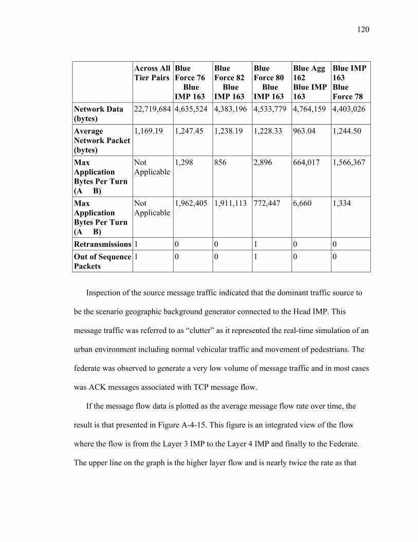
120
Across All Tier Pairs
Blue Force 76 � Blue IMP 163
Blue Force 82 � Blue IMP 163
Blue Force 80 � Blue IMP 163
Blue Agg 162 � Blue IMP 163
Blue IMP 163 � Blue Force 78
Network Data (bytes)
22,719,684 4,635,524 4,383,196 4,533,779 4,764,159 4,403,026
Average Network Packet (bytes)
1,169.19 1,247.45 1,238.19 1,228.33 963.04 1,244.50
Max Application Bytes Per Turn (A � B)
Not Applicable
1,298 856 2,896 664,017 1,566,367
Max Application Bytes Per Turn (A � B)
Not Applicable
1,962,405 1,911,113 772,447 6,660 1,334
Retransmissions 1 0 0 1 0 0 Out of Sequence Packets
1 0 0 1 0 0
Inspection of the source message traffic indicated that the dominant traffic source to
be the scenario geographic background generator connected to the Head IMP. This
message traffic was referred to as “clutter” as it represented the real-time simulation of an
urban environment including normal vehicular traffic and movement of pedestrians. The
federate was observed to generate a very low volume of message traffic and in most cases
was ACK messages associated with TCP message flow.
If the message flow data is plotted as the average message flow rate over time, the
result is that presented in Figure A-4-15. This figure is an integrated view of the flow
where the flow is from the Layer 3 IMP to the Layer 4 IMP and finally to the Federate.
The upper line on the graph is the higher layer flow and is nearly twice the rate as that
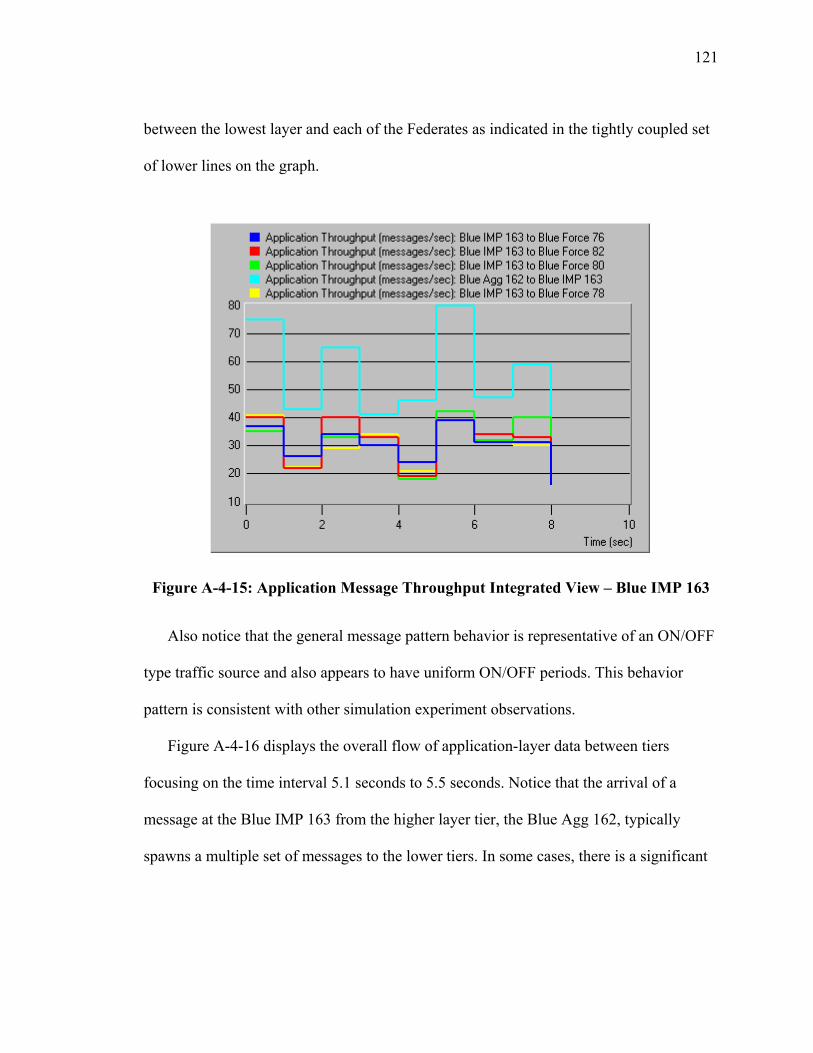
121
between the lowest layer and each of the Federates as indicated in the tightly coupled set
of lower lines on the graph.
Figure A-4-15: Application Message Throughput Integrated View – Blue IMP 163
Also notice that the general message pattern behavior is representative of an ON/OFF
type traffic source and also appears to have uniform ON/OFF periods. This behavior
pattern is consistent with other simulation experiment observations.
Figure A-4-16 displays the overall flow of application-layer data between tiers
focusing on the time interval 5.1 seconds to 5.5 seconds. Notice that the arrival of a
message at the Blue IMP 163 from the higher layer tier, the Blue Agg 162, typically
spawns a multiple set of messages to the lower tiers. In some cases, there is a significant
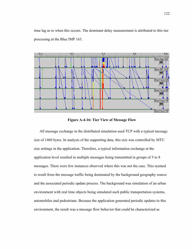
122
time lag as to when this occurs. The dominant delay measurement is attributed to this tier
processing at the Blue IMP 163.
Figure A-4-16: Tier View of Message Flow
All message exchange in the distributed simulation used TCP with a typical message
size of 1460 bytes. In analysis of the supporting data, this size was controlled by MTU
size settings in the application. Therefore, a typical information exchange at the
application level resulted in multiple messages being transmitted in groups of 5 to 8
messages. There were few instances observed where this was not the case. This seemed
to result from the message traffic being dominated by the background geography source
and the associated periodic update process. The background was simulation of an urban
environment with real time objects being simulated such public transportation systems,
automobiles and pedestrians. Because the application generated periodic updates to this
environment, the result was a message flow behavior that could be characterized as
123
ON/OFF with uniform rate of transmission while ON, but varying lengths of time of
being ON.
Because the application aggregated update information into lengthy messages, it was
not possible to determine the flow rate directly relative to an individual element or object
in the simulation. To estimate the flow rate, it is required to know the average number of
active elements in the simulation. This information was not available. The other factor
that is important to acknowledge in this experiment is that the message flow statistics
includes ACK messages generated by the TCP. The impact of this is observed by the fact
that the average network packet size was in the range 1200 bytes, significantly less than
the average 1460 MTU size in observed in the TCP payloads for the message. This
indicates an estimated throughput efficiency of 82 % relative to using UDP.
VI Summary of Observations for Message Flow Characterization
Table A-4-2 below summarizes and compares the three message load studies. Two of
the three samples reflect an ON/OFF traffic pattern. These two, the Ops simulation and
the JFCOM experiment, represent more realistic scenarios than the WSIM RTI
experiment as they were very interactive and involved many Federates that had different
characteristics of movement.
The WSIM RTI experiment represented a sea vessel moving in a continuous circle
and therefore resulted in a strictly uniform stream of update messages. While this
simulation is very simple, it does represent what might be expected from any simulation
that would contain a continuously moving Federate or any Federate that changed state
124
from being stable in a visual space to one of moving. This example could be described as
continuous flows of messages.
These experiments represent important observations and provide evidence to support
our approach for generating message flows for performance measurements and also
support the basis for our proposed analytical model presented in the next section. They
also provide evidence to support a protocol that manages streaming type message flow.
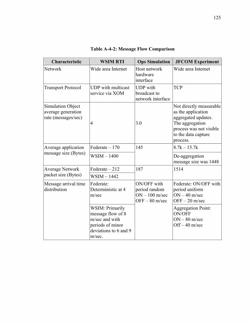
125
Table A-4-2: Message Flow Comparison
Characteristic WSIM RTI Ops Simulation JFCOM Experiment Network Wide area Internet Host network
hardware interface
Wide area Internet
Transport Protocol UDP with multicast service via XOM
UDP with broadcast to network interface
TCP
Simulation Object average generation rate (messages/sec)
4 3.0
Not directly measurable as the application aggregated updates. The aggregation process was not visible to the data capture process.
Federate – 170 8.7k – 15.7k Average application message size (Bytes) WSIM – 1400
145
De-aggregation message size was 1448
Federate – 212 Average Network packet size (Bytes) WSIM – 1442
187 1514
Federate: Deterministic at 4 m/sec
Federate: ON/OFF with period uniform ON – 40 m/sec OFF – 20 m/sec
Message arrival time distribution
WSIM: Primarily message flow of 8 m/sec and with periods of minor deviations to 6 and 9 m/sec.
ON/OFF with period random ON – 100 m/sec OFF – 80 m/sec
Aggregation Point: ON/OFF ON – 80 m/sec Off – 40 m/sec
126
SECTION 5 MESSAGE LOAD ANALYTICAL MODEL
I Introduction
A major complexity in developing initiatives for distributed real-time simulations is
being able to understand traffic loads offered to an open network in order to predict what
expected performance might be achieved. It is important to have a sound analytical model
to form the basis for being able to describe traffic characteristics with appropriate metrics
that can be measured in real application environments. These metrics can then be used
with the analytical model to help predicate expected performance and provide a measure
of scalability across an open network. These metrics take into account packet error and
loss rates, throughput, latency and jitter, and path flows including blocking.
Unfortunately, few controls exist at the host or application layer that can directly
influence each of these metrics at the network layer particularly where the application is
real-time such as that represented by real-time distributed simulations. These
applications, however, can control sending rate and message size. Also, the applications
typically have the ability to prioritize messages. It is therefore desirable to have an
analytical model that has a basis in metrics that are feasible to measure in the operational
overlay network that provide a relationship in a statistical sense to those at the network
layer. This allows for implementation of controls and routing algorithms that can be
based on these performance metrics.
127
Part II of this section presents an initial model developed to support understanding
performance of these applications. It is analytically based on the sum of exponentials and
related assumptions derived from discussions with simulation experts and visual
observation of object behavior in a simulation. This model was implemented in C++ code
as a message generator used in testing of SRMP and early testing of the XOM prototype.
Part III presents the improved analytical model that allows for use of directly
measured performance indicators available in the operational overlay. This approach was
fostered by the knowledge gained through the live simulations studies described in the
previous section and a better understanding of what is achievable in a overlay network
system. The model is based on an ON/OFF traffic model that has derivation from similar
models developed for integration of voice and data and Asynchronous Transfer Mode
(ATM) communications [Kucz73]. Included is a discussion of a simulation model written
for validation of the Poisson arrival process assumption used to simplify the analytical
model approach for aggregation of the ON/OFF traffic loading.
II Exponential Traffic Load Model
The previous section provided results of studies of three simulation environments that
represent the complex nature of the problem It is complicated by the nature of the
application environment as the traffic load is not only specific to a particular simulation,
but also to a simulation scenario. To facilitate early studies of traffic load behavior of
protocols supporting the RT-DVS, a traffic model was developed for use in the GMU C3I
Center Networking and Simulation laboratory (NETLAB) [Wint87]. The development of

128
the model resulted from application of a general systems engineering approach where a
number of informal discussions with experts and observation of visual simulations where
conducted. The traffic was first used to aid performance evaluation of the Selectively
Reliable Multicast protocol developed at GMU C3I Center [Moen01].
The model was constructed around a 4-state process to represent status of a
simulation object in a visual space, where the states represent the status of an object in a
distributed real time simulator as presented in Figure A-5-1. The model was developed to
include the two classes of messages defined in SRMP: Mode 0 message implies no
reliability required and a Mode 1 message requires reliability. The four states are:
1. Object Off state: In this state the object is “off” and is not generating any
messages.
2. Object Idle state: The simulation object is active in the visual space of the
simulation, but is not moving and is stable in a multicast group. In this
state, the object will generate Mode 0 packets at fixed rate. The object will
infrequently (exponential distribution) generate Mode 1 messages.
3. Object Moving state: The simulation object is moving within the current
multicast group. In this state the object will generate Mode 0 packets at a
fixed rate. The object will infrequently (exponential distribution) generate
Mode 1 messages.
4. Object Join state: The simulation object joins a new multicast group. In
this state, the object will generate Mode 1 messages at fixed rate until
established in the new multicast group.
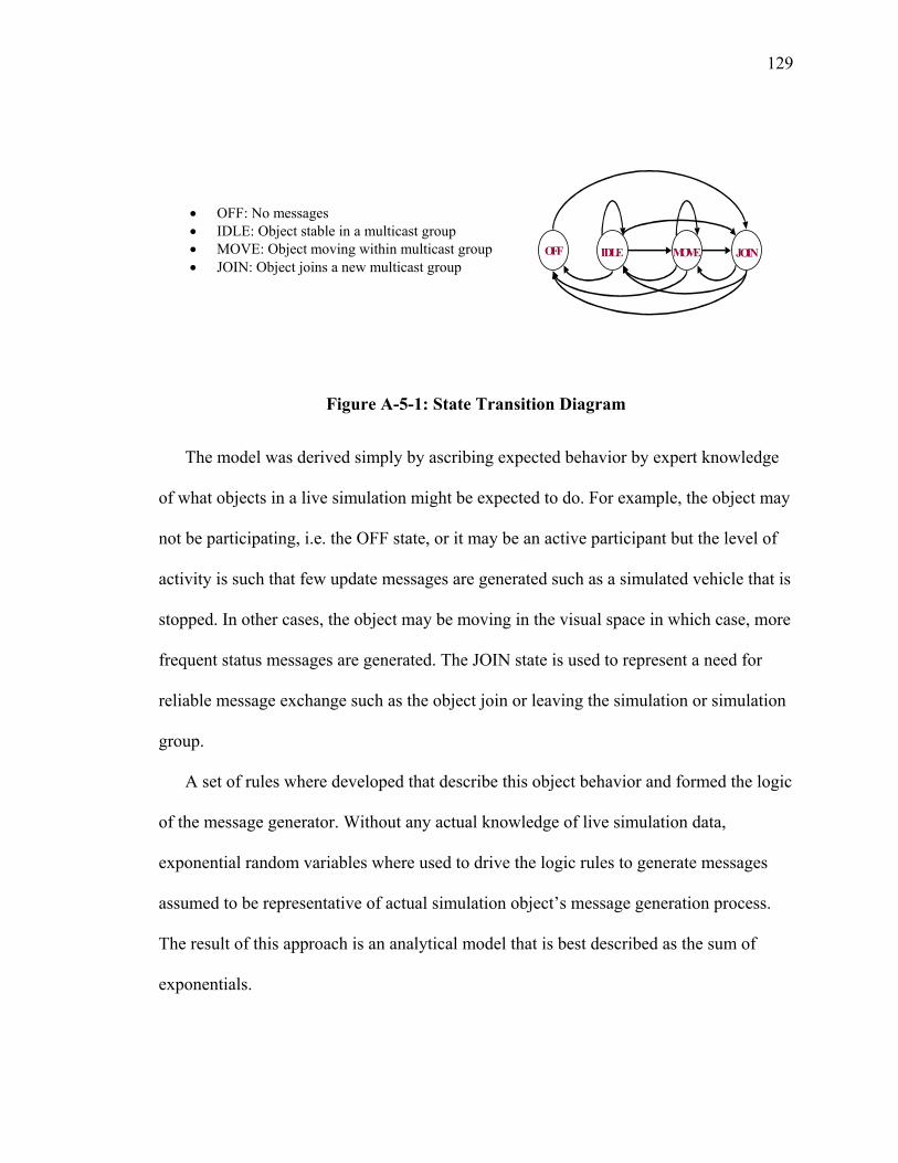
129
Figure A-5-1: State Transition Diagram
The model was derived simply by ascribing expected behavior by expert knowledge
of what objects in a live simulation might be expected to do. For example, the object may
not be participating, i.e. the OFF state, or it may be an active participant but the level of
activity is such that few update messages are generated such as a simulated vehicle that is
stopped. In other cases, the object may be moving in the visual space in which case, more
frequent status messages are generated. The JOIN state is used to represent a need for
reliable message exchange such as the object join or leaving the simulation or simulation
group.
A set of rules where developed that describe this object behavior and formed the logic
of the message generator. Without any actual knowledge of live simulation data,
exponential random variables where used to drive the logic rules to generate messages
assumed to be representative of actual simulation object’s message generation process.
The result of this approach is an analytical model that is best described as the sum of
exponentials.
• OFF: No messages • IDLE: Object stable in a multicast group • MOVE: Object moving within multicast group • JOIN: Object joins a new multicast group
OFF IDLE MOVE JOIN

130
This model represents a discrete event continuous-time Markov chain [Tijm94]. The
state transitions are governed by a Markov chain in which the dependency of the
successive state of the simulation object is only dependent on the object’s current state.
The holding times in each state are, however, exponentially distributed, therefore
defining a continuous-time Markov chain.
The message generator model is defined as a continuous-time stochastic process {X(t),
t≥0} with discrete state space I and
P{X(tn)=in|X(t0)= i0,…,X(tn-1)= in-1} = P{X(tn)=in|X(tn-1)= in-1}
for all 0 ≤ t0 < … < tn-1 < tn and i0, …, in-1, in ∈ I.
Under this definition, two rules are established for the discrete state space to change state:
1. If the system jumps to state i, it stays in state i an exponentially distributed time
with a mean µ independently of how the system reached state i and how long it
took to get there.
2. If the system leaves state i, it jumps to state j with probability pij(j≠i) independent
of the duration of the stay in state i, where ∑j≠i pij = 1 for all i∈ I.
Given this definition of the model, a traffic generator was programmed in C++ to
represent this four-state model. Messages are generated and transmitted to the multicast
group at a rate and type (Mode) for each object based on the current state of the object. In
the current characterization of the model, all distributions are assumed to be exponential;
though the model is built to allow substitution of different distributions for special case
analysis or where well known distributions exist that prove to represent distributed virtual
simulation data better than the exponential.
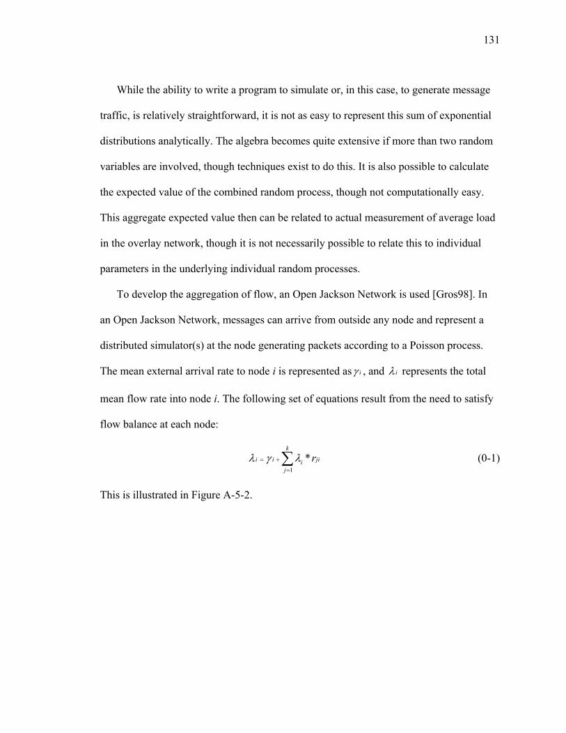
131
While the ability to write a program to simulate or, in this case, to generate message
traffic, is relatively straightforward, it is not as easy to represent this sum of exponential
distributions analytically. The algebra becomes quite extensive if more than two random
variables are involved, though techniques exist to do this. It is also possible to calculate
the expected value of the combined random process, though not computationally easy.
This aggregate expected value then can be related to actual measurement of average load
in the overlay network, though it is not necessarily possible to relate this to individual
parameters in the underlying individual random processes.
To develop the aggregation of flow, an Open Jackson Network is used [Gros98]. In
an Open Jackson Network, messages can arrive from outside any node and represent a
distributed simulator(s) at the node generating packets according to a Poisson process.
The mean external arrival rate to node i is represented as iγ , and iλ represents the total
mean flow rate into node i. The following set of equations result from the need to satisfy
flow balance at each node:
1
*k
i i jiij
rλ γ λ= +
=∑ (0-1)
This is illustrated in Figure A-5-2.
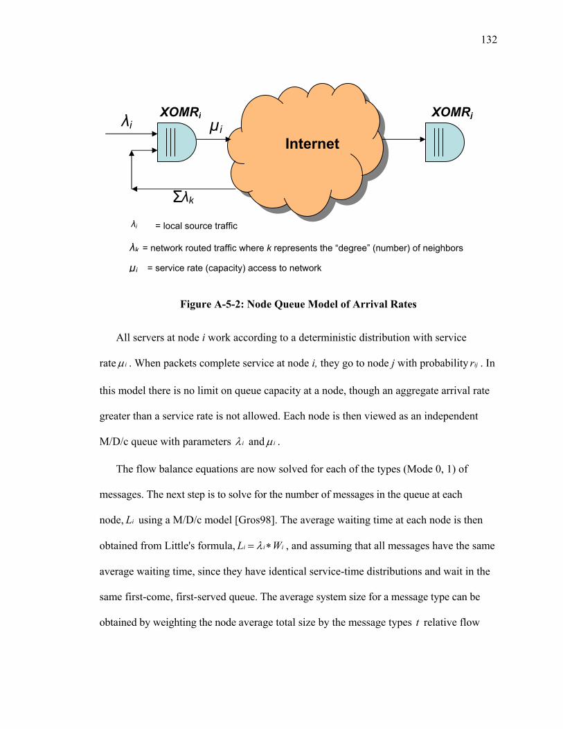
132
Figure A-5-2: Node Queue Model of Arrival Rates
All servers at node i work according to a deterministic distribution with service
rate iµ . When packets complete service at node i, they go to node j with probability ijr . In
this model there is no limit on queue capacity at a node, though an aggregate arrival rate
greater than a service rate is not allowed. Each node is then viewed as an independent
M/D/c queue with parameters iλ and iµ .
The flow balance equations are now solved for each of the types (Mode 0, 1) of
messages. The next step is to solve for the number of messages in the queue at each
node, iL using a M/D/c model [Gros98]. The average waiting time at each node is then
obtained from Little's formula, i i iL Wλ= ∗ , and assuming that all messages have the same
average waiting time, since they have identical service-time distributions and wait in the
same first-come, first-served queue. The average system size for a message type can be
obtained by weighting the node average total size by the message types t relative flow
XOMRi XOMRjµi λi
Internet
λi = local source traffic
λk = network routed traffic where k represents the “degree” (number) of neighbors
µi = service rate (capacity) access to network
λk Σ
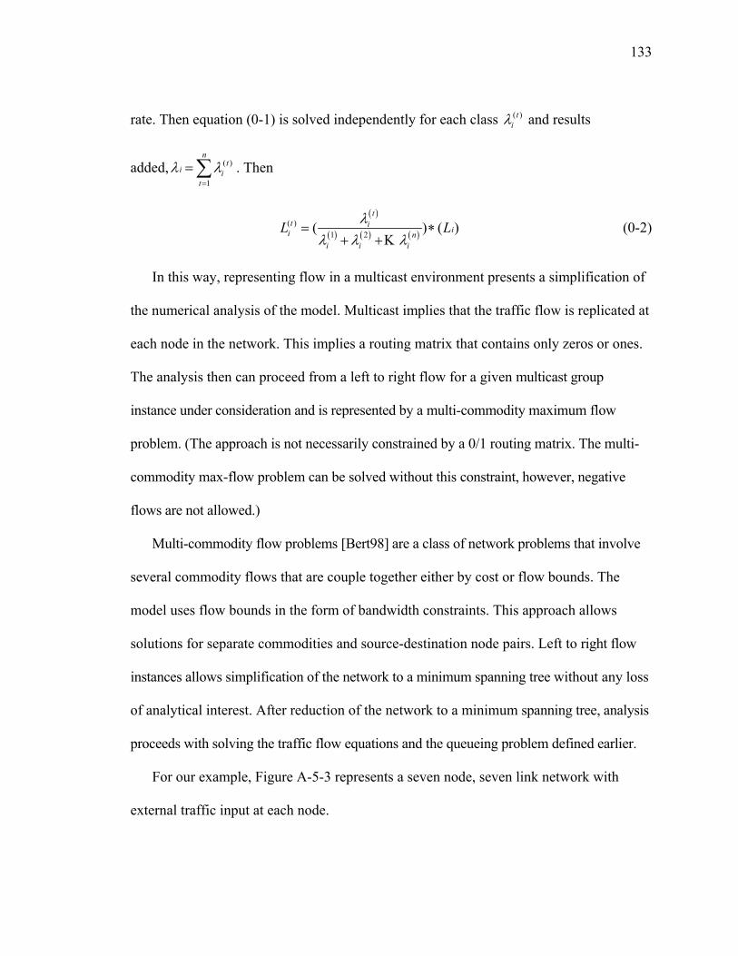
133
rate. Then equation (0-1) is solved independently for each class ( )tiλ and results
added, ( )
1
nt
i it
λ λ=
=∑ . Then
( )
( ) ( ) ( )( )
1 2( ) ( )t
t iii n
i i i
L Lλλ λ λ
= ∗+ +K
(0-2)
In this way, representing flow in a multicast environment presents a simplification of
the numerical analysis of the model. Multicast implies that the traffic flow is replicated at
each node in the network. This implies a routing matrix that contains only zeros or ones.
The analysis then can proceed from a left to right flow for a given multicast group
instance under consideration and is represented by a multi-commodity maximum flow
problem. (The approach is not necessarily constrained by a 0/1 routing matrix. The multi-
commodity max-flow problem can be solved without this constraint, however, negative
flows are not allowed.)
Multi-commodity flow problems [Bert98] are a class of network problems that involve
several commodity flows that are couple together either by cost or flow bounds. The
model uses flow bounds in the form of bandwidth constraints. This approach allows
solutions for separate commodities and source-destination node pairs. Left to right flow
instances allows simplification of the network to a minimum spanning tree without any loss
of analytical interest. After reduction of the network to a minimum spanning tree, analysis
proceeds with solving the traffic flow equations and the queueing problem defined earlier.
For our example, Figure A-5-3 represents a seven node, seven link network with
external traffic input at each node.
134
Figure A-5-3: Example Network
The minimum spanning tree reduction, presented in Figure A-5-4, reduces the
network to a seven node, six link network. The reduction is allowed since we are
interested in the flow into node 7; traffic originating from node 1 destined to node 2,
leaves the network at node 2 and is not forwarded. (While node 2 performance may be of
interest, performance analysis of node 2 can be solved as another instance of the problem
where the minimum spanning tree is two nodes, with one link.) The same node 1 traffic is
replicated and offered to node 3 in the minimum spanning tree.
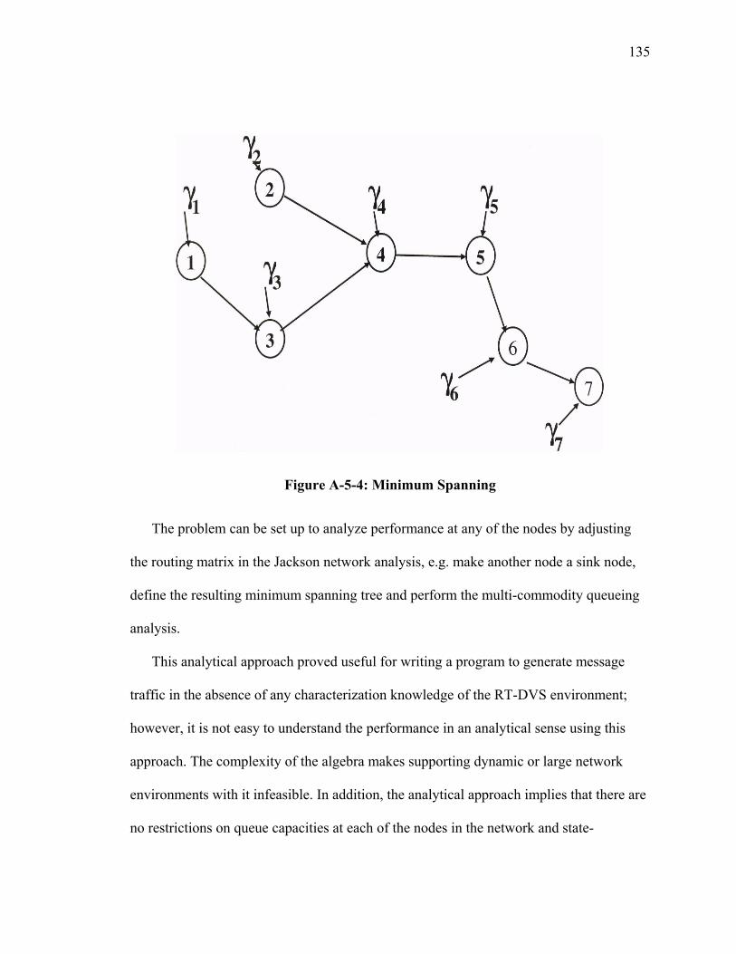
135
Figure A-5-4: Minimum Spanning
The problem can be set up to analyze performance at any of the nodes by adjusting
the routing matrix in the Jackson network analysis, e.g. make another node a sink node,
define the resulting minimum spanning tree and perform the multi-commodity queueing
analysis.
This analytical approach proved useful for writing a program to generate message
traffic in the absence of any characterization knowledge of the RT-DVS environment;
however, it is not easy to understand the performance in an analytical sense using this
approach. The complexity of the algebra makes supporting dynamic or large network
environments with it infeasible. In addition, the analytical approach implies that there are
no restrictions on queue capacities at each of the nodes in the network and state-
136
independent routing probabilities can be applied at each node in the network. This is not
the case for RT-DVS as is demonstrated by the results of prototype performance testing
presented in Section 6. The knowledge gained from studying this early analytical strategy
resulted in a much improved model that can readily be applied to the overlay concept.
This model is presented in the following paragraphs.
III ON/OFF Traffic Model
The motivation for a good and efficient analytical model is to reduce dependencies on
simulation to provide the basis of understanding network performance of the overlay. In
addition, it is highly desirable to have a near real time correlation of measured traffic load
to a simple analytical model so that a routing algorithm can use the information for
dynamic optimization of the overlay network. This motivation is not new and has
fostered many ideas to accomplish this. Heffes [Heff86] introduced the idea of Markov
modulated characterization to support statistical multiplexing of packetized voice sources
together with data traffic using the Markov modulated Poisson process (MMPP). The
approach is used to support ATM networking analysis and design. Kang [Kang95]
refined the approach for two-state MMPP modeling of superposed traffic streams.
Ma [MaJo04] expands upon these ideas and presents a simple, physical-based traffic
model using a two state (ON/OFF) Markov process to model traffic from heterogeneous
sources. The approach results in ability to express traffic statistics in terms of three
physically identifiable or measurable usage parameters: bandwidth used when ON,
fraction of time utilized, and the number of ON times per unit of time.
137
The traffic characterization studies of real time simulations presented in Section 4
showed these traffic traces to have very similar properties to this ON/OFF process. This
ON/OFF approach is analytically appealing as it can be represented by Markov
Modulated Poisson Process. It also allows for consideration of other traffic distributions
such as Pareto, though analytically, the available statistics change. Specifically,
traditional statistics such as mean flow rate or variance are no longer available, as Pareto
distributions do not necessarily have all their moments. However, the statistics that are
available may still be useful. For example, the probability of an access link being in
overload condition and the probability of how long it is likely to remain in overload,
statistically, are indicators of stability in the overlay network.
Another reason that this strategy is appealing is that Simon [Simo04] has
demonstrated the value of using flow control mechanisms based on this approach. He has
presented simulation results of using rate based admission control at the access point to
provide a certain level of expected performance across the overlay network. This
mechanism provides a measure of control and predicts message loss across the overlay
network using a traffic model similar to that presented by Bianchi [Bian00].
Using this ON/OFF strategy allows for representing an aggregated traffic trace from
N independent ON/OFF sources. This approach is very representative of the original 4
state model developed for use as a traffic generator described in the previous section. The
following paragraphs describe an analytical approach suitable for representation of the
expected traffic load that could be used as part of the path management in an overlay
network.
138
According to Fischer [Fisc93], the first use of the MMPP for traffic analysis was in
Naor [Naor71]. Many papers and books now provide examples [Kucz73] of the use of
MMPP with Fischer [Fisc93] presenting a number of results for easy understanding and
establishing the basis for a variety of applications. In the case of our studies of simulation
traffic, the characterization reflects the ON/OFF model, however with what appears to be
somewhat discrete ON/OFF periods and also where the ON/OFF relationship represents a
higher or lower rate of message arrivals rather than on or off. This actually serves to
simplify the problem and readily supports our desires to have measurable parameters that
can be used to impact the overlay routing performance in line with the Simon [Simo04]
approach for admission rate control.
Bianchi [Bian00] provides a flexible approach to representing ON/OFF traffic
models. His approach allows for the superposition of independent homogeneous ON/OFF
variable rate traffic sources with exponential distribution of ON/OFF times. By assuming
independence of each traffic source, the approach allows for calculation of the average
source traffic rate by simply scaling by the time ON relative to the sum of time ON and
the time OFF.
The independence assumption also allows for defining a process where the
probability of i sources over k active at time t as a Bernoulli distribution. This is similar
to the discrete time slot analysis for ATM communications system where k represents the
time slots and i represents the arrival of packet. This is a discrete time, geometric inter-
arrival process which is a Bernoulli process [Pitt00, Star94].

139
This provides for a straightforward analytical solution to develop the conditional
probabilities that a source is in the ON state. However, the next steps in the process
model for throughput analysis are complex as the real interest is in having an expression
for the capacity received by a new source in terms of capacity already allocated in the
access link for a node in the overlay (Simon [Simo04] approach to admission control).
Bianchi accomplishes this by developing an approximation based on a fixed rate
traffic model rather than a variable rate model. The entire derivation is available in
[Bian00] and the specific results of interest are presented here.
( )m t is defined as the number of additional new traffic sources and ( )k t as the number
of sources already in service. The assumption is made that new sources fairly share the
capacity left available by those already in service, then the rate (or bandwidth) ( )rB t
instantly available to the new sources is approximated by
( )max ( ) ,0( ) min ,
( ) 1r p
C k t BB t B
m t− ∗
= + (0-3)
where B is the traffic rate (bandwidth) of sources already in the system and pB is the
rate of new sources. C is the link capacity of the system.
There are certain properties of this model that make it appealing to the overlay
problem. Specifically, we know what the link capacity is or can at least estimate it. We
are able to measure or count how many sources are active, at least in a statistical sense,
therefore allowing decision making at the local node as to ability to allow new sources
into the system without degradation of in service sources.
140
However, there are two shortfalls in this approach. The first is that the model assumes
there are no messages generated in the OFF state. We know from studying the targeted
simulation environment that this is not the case. The model would therefore need to be
adjusted to reflect this requirement. The second shortfall is that it still is somewhat
computationally intensive. This results from the input Poisson process assumption that
gives a 2N state space for N independent sources.
Another approach is to consider taking advantage of traffic studies that indicate that
the simulation environment has relatively deterministic traffic generation rates and that
the ON/OFF periods generally have relatively uniform distributions of alternating ON
and OFF periods. The other observation of the measured traffic is that the simulations
tend to have fixed length messages sizes. This leads to the consideration of an approach
that uses an aggregated flow M/D/1 queue model which appears to be easier to use and
has basis similar to the M/D/c model presented earlier in this section.
For the analysis, an assumption is that application data sources have stationary
statistics and are independent. The previous section provided evidence that the message
traffic behavior is deterministic, so the assumption is valid. The assumption allows us to
then use a multiplier, N, for summing of multiple sources. This also implies that as the
number of sources increases, that the traffic load variance will also increase linearly. Ma
[MaJo04] and Pitts [Pitt00] use this to simplify the analytical model.
The approach results with the idea of flow aggregation. Pitts [Pitt00] presents an
argument that flow aggregation is possible based on the assumption that the output port,
or in our case the access link to the network from the XOM, has much greater capacity
141
than the offered source rate of message arrivals. In the cases studied this assumption also
was valid. Further, this assumption can be forced always to be valid in the
implementation of the XOM by imposing it as a constraint in allowing new flows or
sources of traffic either directly or by using a threshold measurement value that provides
warning that the XOM is no longer able to offer expected level of service.
If this threshold is defined as the available service rate C, then the rational of Ma
[MaJo04] and Pitts [Pitt00] can be used to construct a two-state overflow model where
the aggregate process is either in the ON state, meaning the message arrival rate exceeds
the output service capacity C (or defined threshold) and an OFF state where the arrival
rate is less than then the service capacity (threshold), but not necessarily zero.
A measure in the XOMR prototype counts the message arrivals in time intervals and
provides for a threshold parameter associated with the capacity of the XOM node. This is
implemented using a Web service interface and provides for display of these measures
near real time. The two-state approach, therefore, can be used to directly apply
performance management to the overlay network in near real time, which is the objective.
The ON/OFF model analytical development details are presented in Kang [Kang95],
Bianchi [Bian00], Ma [MaJo04] and Pitts [Pitt00]. An approach customized to this
application is presented here for completeness and includes results from a simulation
written to demonstrate the ON/OFF traffic relationship to studied simulations and
confirms that the assumptions used for the simplification are valid.
The messages generated by a simulation can be characterized as message flow having
a mean ON time of ONT and a message arrival rate of λ (messages/s). This gives a per
142
flow average of ONT λ∗ . In the XOM, it is possible to measure the mean load of messages
arriving which we define as MA , then the rate of flows arriving is easily calculated by
MA
ON
AFT λ
=∗
(0-4)
This traffic model applies to N sources of traffic so this must be modified to represent
the aggregate which reduces the state space from 2N to two. This is illustrated in Figure
A-5-5. We then define ONT to be the time that the process is in excess of the threshold C
and OFFT to be the period of time that the arrival process is less than the threshold. The
characterization of the RT-DVS presented in Section 4 indicated a deterministic source
message size that arrives at a constant rate. This allows describing the service rate as
deterministic. In addition, we assume that the overlay host has a single connection to the
supporting underlying network. By definition, this allows application of queuing analysis
using the M/D/1 queue model for the study of the arrival process and the departure
process at an overlay node. Knowing C and λ , the maximum number of message flows
is
0CNλ
= (0-5)
Similar to Pitts [Pitt00], we make the assumption that message flow arrival is
memoryless as a result of user activity in the application triggering the flow. Using(0-4),
we can define the offered message load in terms of message flows as
MA ON
AA F Tλ
= = ∗ (0-6)
143
For our analysis, we are interested in the probability of a message being lost at a node as
a result of finding the service buffer full upon arrival. Since the application environment
is real-time, when a message is lost it is not recovered and leaves the system. This is
equivalent to the probability of the message being blocked, that is, the steady state
probability that the buffer is full when the message flow arrives. By definition, this
allows use to apply the Erlang B call waiting formula described in Gallager [Gall83] and
Gross [Gros98]. This leads directly to use of the Erlang call waiting formula as a
representation for probability of a message flow being blocked as developed by Pitts
[Pitt00] for flow analysis:
0
00
0
0 0
0
0 00
!
! !
N
r NN
r
A NN N AD
A A Nr N N A=
∗ − = + ∗ − ∑
(0-7)
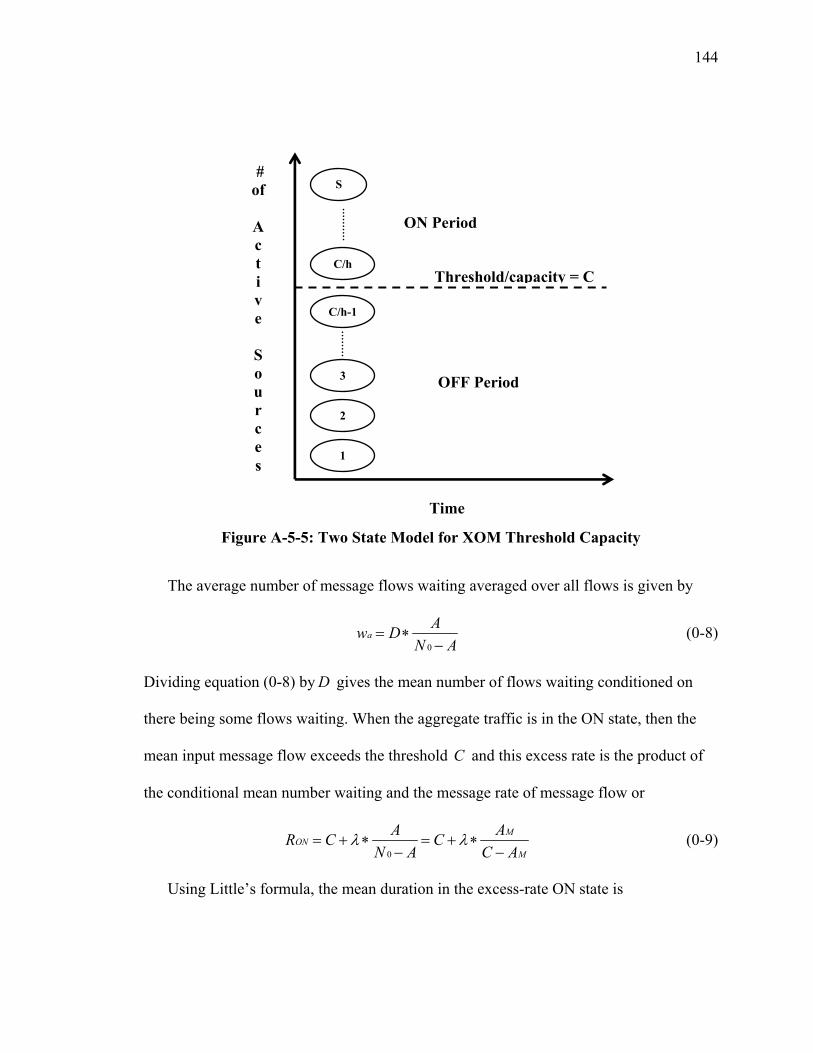
144
Figure A-5-5: Two State Model for XOM Threshold Capacity
The average number of message flows waiting averaged over all flows is given by
0
aAw D
N A= ∗
− (0-8)
Dividing equation (0-8) by D gives the mean number of flows waiting conditioned on
there being some flows waiting. When the aggregate traffic is in the ON state, then the
mean input message flow exceeds the threshold C and this excess rate is the product of
the conditional mean number waiting and the message rate of message flow or
0
MON
M
A AR C CN A C A
λ λ= + ∗ = + ∗− −
(0-9)
Using Little’s formula, the mean duration in the excess-rate ON state is
# of
Ac t i v e
Sou r c e s
Time
Threshold/capacity = C
1
C/h-1
C/h
2
S
3 OFF Period
ON Period

145
A w wON
Aw F t tT
= ∗ = ∗ (0-10)
and rearranging and substituting for w results in
0
ON ONw
T T At w DA A N A
= ∗ = ∗ ∗−
(0-11)
Then the conditional mean delay in the ON state is given by
0
( ) w ON ON
M
t T TT onD N A C A
λ ∗= = =
− − (0-12)
To calculate the rate in the OFF state, OFFR , we make use of the fact that the long run
probability that the aggregate process is in the ON state is the same as the probability that
a message flow is delayed, or D . This is equal to the long run portion of time in the ON
state
( )( ) ( )
T on DT on T off
=+
(0-13)
Therefore,
1( ) ( ) DT off T onD−
= ∗ (0-14)
The mean load in messages per second as the weighted sum of the rates in the ON and
OFF states is
( )1M ON OFFA D R D R= ∗ + − ∗ (0-15)
Therefore OFFR is
1
M ONOFF
A D RRD
− ∗=
− (0-16)

146
This completes the development of an aggregated arrival process to allow describing
the process in terms of packet flows. This approach leads directly to the concept of
associating these flows with group management in the overlay network. A source would
generate packet flows to a multicast group. These groups can then be aggregated for
efficient routing in the overlay network. The aggregation of flows can be represented in
this analytical model and allow for use in understanding queuing behavior in the XOM as
presented in Figure A-5-2 above.
Adopting the assumption that the excess rate message arrivals in the ON state are
geometrically distributed and that the free periods, or the periods of less than excess rate
arrivals, are also geometrically distributed, then the queue overflow probability is given
by Pitts [Pitt00] as
( )
( )
111( ) 11
x
ON ON
M
OFF OFF
T R CDP xC A
T C R
λ
+ − ∗ −∗ = ∗
− − ∗ −
(0-17)
The firs part of this expression represents the probability that an arriving packet is an
excess-rate arrival given by M
DC Aλ ∗−
. The second term in the expression represents the
geometric progression of the status of the queue and is the probability that the queue
exceeds x messages. Since this are independent events, multiplying the terms together
results with desired expression for queue overflow probability as presented by equation
(0-17).
147
IV Poisson Assumption
Earlier in this Section, a key assumption allowed the straightforward use of the
aggregation model based on M/D/1 analysis. It is important to validate this assumption
using the understanding gained in the real time simulations studied. The assumption was
that this is a memoryless process therefore allowing a Poisson arrival.
To understand what the impact of using the Poisson arrival might be in the analysis of
a process where there are a large number of sources being aggregated, a computer
program was written to simulate the generation of a large number of ON/OFF sources
where the message arrival process used a random exponential distribution for source
generation. Each source generates messages at the rate of 4λ = messages per second
when in the ON state. This rate was chosen as representative of the observed rate in the
traffic studies. The ON/OFF times of the sources were equally weighted as this was also
the observed case in the studies of live simulations. The program was written to generate
610 messages. Accounting was accomplished by noting message arrival time in simulated
time. The program first counts and records the number of messages generated in 10ms
interval and then further aggregating the counting process for 100ms and then 1000ms.
By calculating the mean and variance of each of this counting process, it allows for
testing the similarity of the message aggregation process. The details of this procedure
are described by Stallings [Stal98] and Embrechts [Embr02], who define the parameter
( )0 1β β< < to indicate the degree of self-similarity. β is then used to calculate the
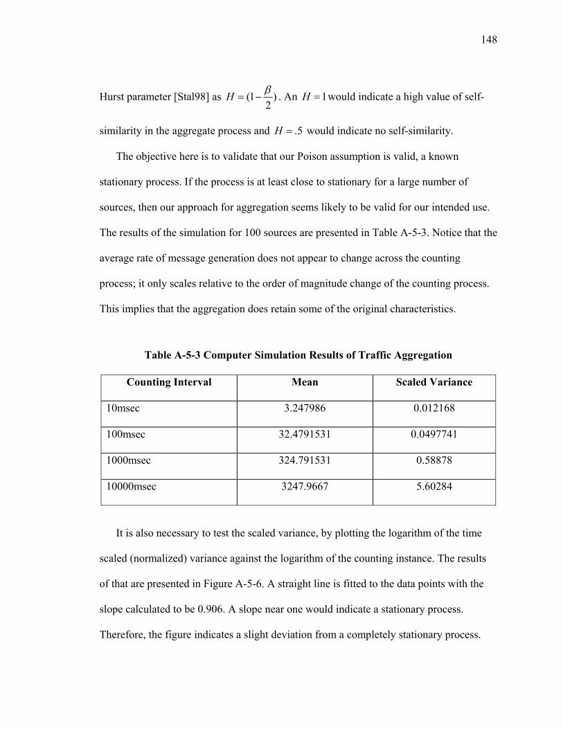
148
Hurst parameter [Stal98] as (1 )2
H β= − . An 1H = would indicate a high value of self-
similarity in the aggregate process and .5H = would indicate no self-similarity.
The objective here is to validate that our Poison assumption is valid, a known
stationary process. If the process is at least close to stationary for a large number of
sources, then our approach for aggregation seems likely to be valid for our intended use.
The results of the simulation for 100 sources are presented in Table A-5-3. Notice that the
average rate of message generation does not appear to change across the counting
process; it only scales relative to the order of magnitude change of the counting process.
This implies that the aggregation does retain some of the original characteristics.
Table A-5-3 Computer Simulation Results of Traffic Aggregation
Counting Interval Mean Scaled Variance
10msec 3.247986 0.012168
100msec 32.4791531 0.0497741
1000msec 324.791531 0.58878
10000msec 3247.9667 5.60284
It is also necessary to test the scaled variance, by plotting the logarithm of the time
scaled (normalized) variance against the logarithm of the counting instance. The results
of that are presented in Figure A-5-6. A straight line is fitted to the data points with the
slope calculated to be 0.906. A slope near one would indicate a stationary process.
Therefore, the figure indicates a slight deviation from a completely stationary process.
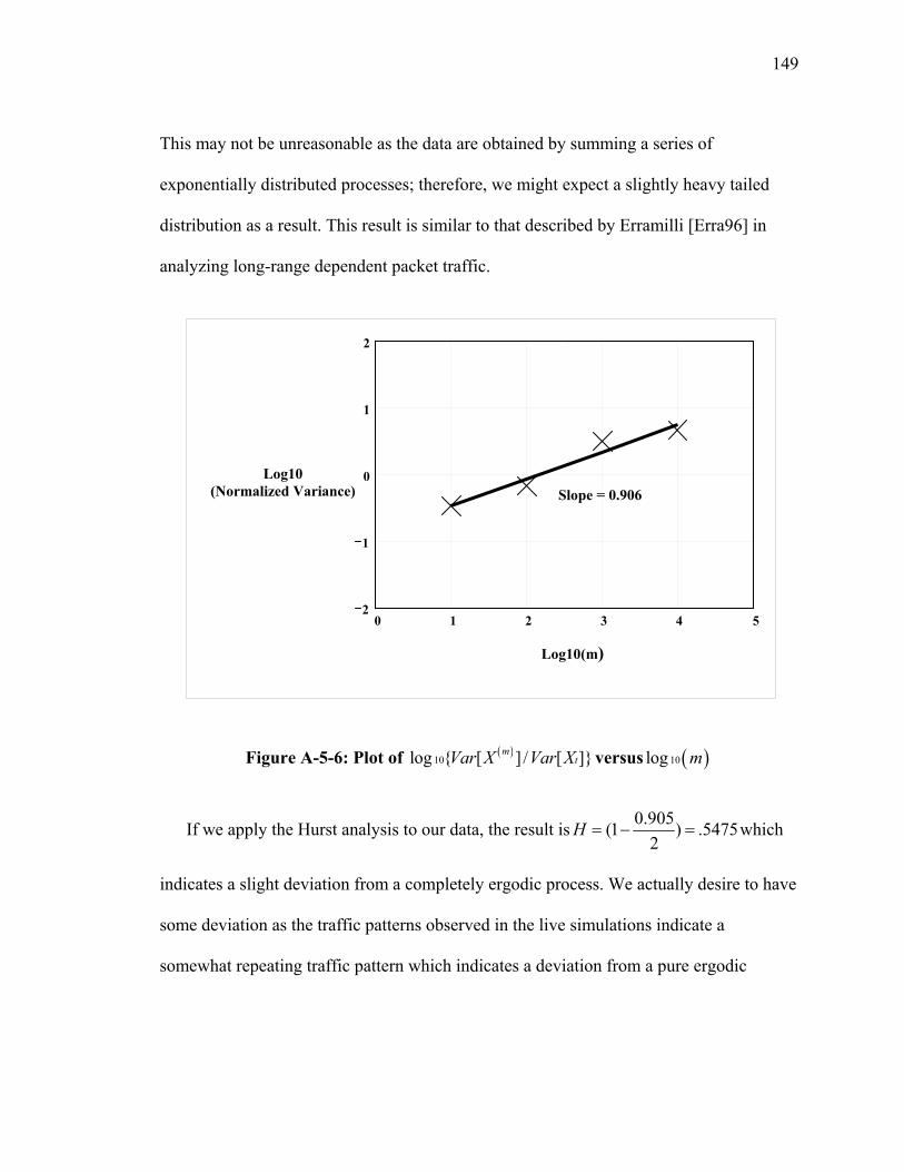
149
This may not be unreasonable as the data are obtained by summing a series of
exponentially distributed processes; therefore, we might expect a slightly heavy tailed
distribution as a result. This result is similar to that described by Erramilli [Erra96] in
analyzing long-range dependent packet traffic.
Figure A-5-6: Plot of ( )10log { [ ] / [ ]}m
tVar X Var X versus ( )10log m
If we apply the Hurst analysis to our data, the result is 0.905(1 ) .54752
H = − = which
indicates a slight deviation from a completely ergodic process. We actually desire to have
some deviation as the traffic patterns observed in the live simulations indicate a
somewhat repeating traffic pattern which indicates a deviation from a pure ergodic
Slope = 0.906
0 1 2 3 4 52
1
0
1
2
Log10(m)
Log10 (Normalized Variance)
150
process. The conclusion is that the Poisson assumption is adequate for this ON/OFF
model.
V Summary
The Section provides for an analytical approach to form the basis for understanding
the overall expected performance of overlay multicast in the distributed simulation
environment. The approach focused on having an analytical model that has directly
measurable parameters available in the actual operation environment of the overlay. The
concept is that these parameters could then be used in a routing algorithm for delivery of
messages with consideration of the expected performance. This is important for overlay
multicast as the overlay protocol essentially has no ability to control the service
performance of the lower layer network.
Part II of this section presented the first model developed for support of
understanding performance of these applications. This model proved to be representative
of actual traffic and therefore useful in the performance understanding of the prototype
protocol in the absence of live traffic. The model was based on the sum of exponentials
as derived from observing behavior of a single object in a visual simulation. The model is
implemented in C++ and has been used early prototype testing of XOM.
The knowledge gained in this early traffic generator was applied in the development
of an analytical model that allows for use of directly measured performance indicators
available in the operational overlay. Part III of this section presented the proposed
analytical model. The approach was based on an ON/OFF traffic model that has
151
derivation from similar models developed for voice and Asynchronous Transfer Mode
(ATM) communications. Part IV of this section presented results of a simulation model
written for validation of the Poisson arrival process assumption used to simplify the
analytical model approach for aggregation of the ON/OFF traffic loading. The next
Section demonstrates the use of this analytical model in some examples that are specific
to the XOMR and relate to measured performance results of the laboratory test of the
current XOMR prototype.
152
SECTION 6 PERFORMANCE CONSIDERATIONS FOR OVERLAY MULTICAST
I Introduction
The previous section presented an analytical approach to understanding the
performance of overlay multicast in support of distributed simulations. This section
provides a link between the analytical model and evaluation of an early prototype of the
XOM overlay. The purpose is to validate the analytical model and serve to form a basis
of the proposed architecture.
Part II of this section presents results of laboratory tests of the current XOMR
prototype conducted in the GMU C3I Laboratory. The testing objective was to
demonstrate message throughput of the basic message routing functions. The specific
performance interest in the testing was to measure message throughput of the
send/receive functions and relate this to an understanding of the impact of the n-degree or
the number n of reflect messages that might be achievable from an XOMR. The n-degree
factor is a significant parameter as it represents the ability of the XOMR to replicate
messages to multiple paths or channels, therefore a driving force behind overall path
construction and path optimization.
The second factor of interest in the XOMR performance is the optimum diameter of
the overlay system, or the number of XOMRs that could conceivably be cascaded before
message loss would be unacceptable. For example, if the end-to-end message loss
153
objective across a ten-node overlay system is be to less than 1%, then the loss allocation
to each XOM node must be less than 0.1%. Measuring message loss in the laboratory
tests and using the information for validation of the analytical model also gives a tool to
help establish thresholds that can be used for determining operational overlay system
diameter.
The third facto of interest is end-to-end path delay. This is estimated by summing the
processing delays of the nodes in the path as well as the link transmission delay across
the underlying network between the overlay nodes.
Part III of this section discusses key aspects of the proposed architecture influenced
by results from laboratory tests as well as from the study of the live simulations discussed
in Section 4.
II Performance Studies of the XOMR Prototype
The initial test environment was established in the George Mason University (GMU)
C3I Center Network Modeling and Simulation Laboratory. The test configuration is
presented in Figure A-6-1. The configuration consisted of four XOMRs, each operating
on separate subnet LAN segments. These four segments were connected together via a
single IP router to represent a WAN. The C++ MulticastRouter module was used in the
XOMRs, providing better performance than the original Java MulitcastRouter This
configuration represents a 3-degree routing function, where degree means number of
paths required for the XOMR message replication and forwarding.
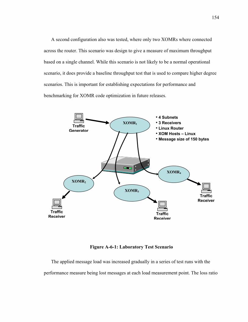
154
A second configuration also was tested, where only two XOMRs where connected
across the router. This scenario was design to give a measure of maximum throughput
based on a single channel. While this scenario is not likely to be a normal operational
scenario, it does provide a baseline throughput test that is used to compare higher degree
scenarios. This is important for establishing expectations for performance and
benchmarking for XOMR code optimization in future releases.
Figure A-6-1: Laboratory Test Scenario
The applied message load was increased gradually in a series of test runs with the
performance measure being lost messages at each load measurement point. The loss ratio
XOMR2
XOMR4
XOMR3
XOMR1 Traffic Generator
Traffic Receiver Traffic
Receiver
Traffic Receiver
• 4 Subnets • 3 Receivers • Linux Router • XOM Hosts – Linux • Message size of 150 bytes

155
was calculated in plotted against offered message load. Multiple runs where conducted.
The summary results are presented in Figure A-6-2. Loading tests where stopped when
traffic loads caused the loss ratio to exceed 1 %. This point represents the design
performance goal of a single XOM and assists in establishment of an operating threshold.
This threshold is then used to establish an operating point so that a single XOM node
does not have message loss greater than 0.1%. This maintains the integrity of the overlay
system under the definition of overlay diameter described earlier.
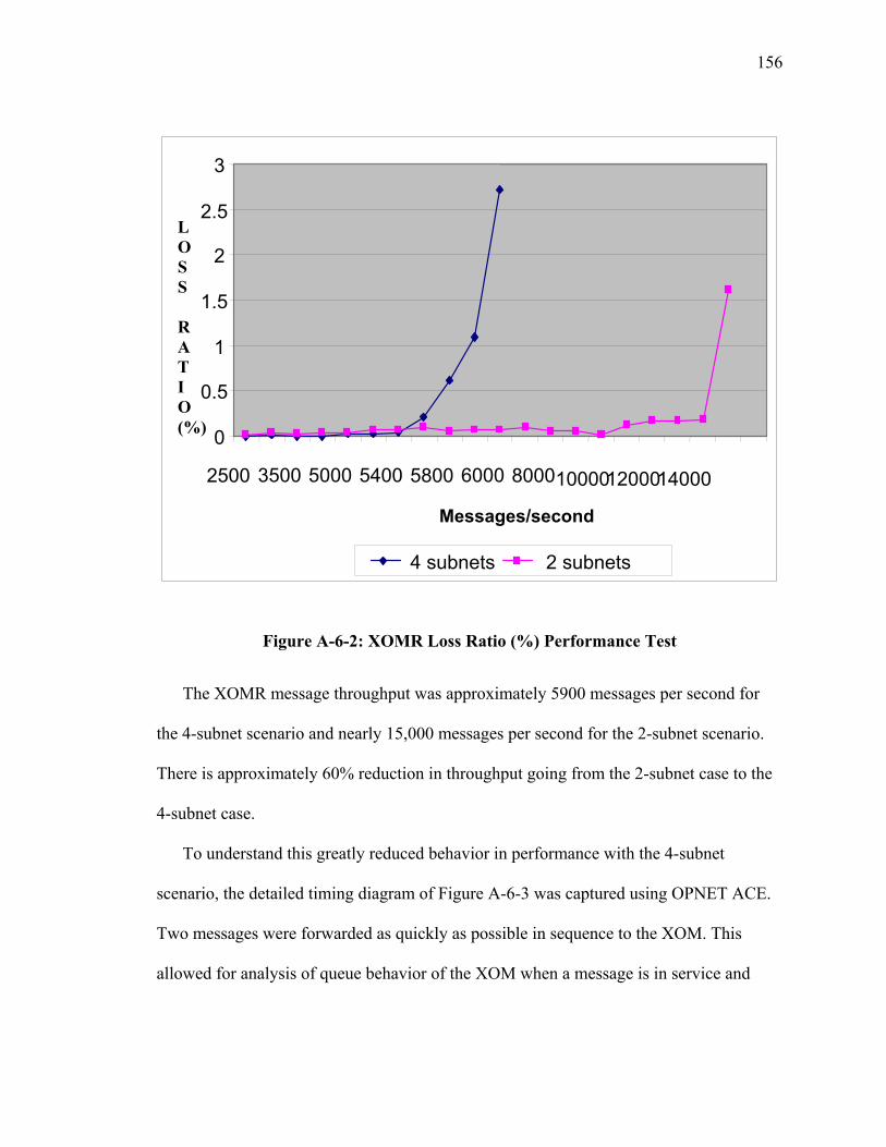
156
Figure A-6-2: XOMR Loss Ratio (%) Performance Test
The XOMR message throughput was approximately 5900 messages per second for
the 4-subnet scenario and nearly 15,000 messages per second for the 2-subnet scenario.
There is approximately 60% reduction in throughput going from the 2-subnet case to the
4-subnet case.
To understand this greatly reduced behavior in performance with the 4-subnet
scenario, the detailed timing diagram of Figure A-6-3 was captured using OPNET ACE.
Two messages were forwarded as quickly as possible in sequence to the XOM. This
allowed for analysis of queue behavior of the XOM when a message is in service and
0
0.5
1
1.5
2
2.5
3
2500 3500 5000 5400 5800 6000 80001000012000 14000 Messages/second
L O S S R A T I O (%)
4 subnets 2 subnets
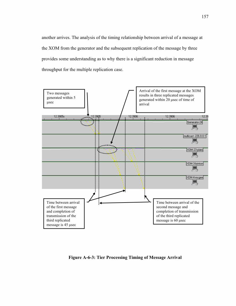
157
another arrives. The analysis of the timing relationship between arrival of a message at
the XOM from the generator and the subsequent replication of the message by three
provides some understanding as to why there is a significant reduction in message
throughput for the multiple replication case.
Figure A-6-3: Tier Processing Timing of Message Arrival
Two messages generated within 5 µsec
Arrival of the first message at the XOM results in three replicated messages generated within 20 µsec of time of arrival
Time between arrival of the first message and completion of transmission of the third replicated message is 45 µsec
Time between arrival of the second message and completion of transmission of the third replicated message is 60 µsec

158
The graph indicates the impact of an arrival of an additional message when one
message is already is in service. When the first message arrives, it enters into service and
completes the replication of three messages before it can start processing the arrival of
the second message. Since the second message must wait for the first to finish service, it
appears to take more than twice the time required by the first before it completes
processing even though it arrived only 5 secµ later than the first.
Considering the total process including the time for completion of service (processing
of the arrival and replication and transmission of three messages), then the analysis of a
single arrival implies that the service rate expected should be 1/ .000045 22.2k=
messages per second. For the second message, the implied service rate is
1/ 0.000060 16.7k= messages per second.
If the arrival process was a memoryless one such as Poisson, then queue build up and
overflow occur in a gradual process. The expectation for such an arrival process is that
the system would respond by servicing the queue in the gaps of new random arrivals
which tends to smooth out the knee of the failure curve or have a more gradual failure
characteristic.
If the system is characterized by more deterministic arrivals (e.g., the arrival process
has memory), then the result has a sharper curve of when the queue overflows. This
behavior is similar to that observed in Figure A-6-2 and results from the fact that the
message generator used was deterministic with fixed length message sizes. This
characteristic is similar to that observed in the live simulations presented earlier.
159
The first laboratory tests conducted considered batch arrivals similar to the situation
presented in Figure A-6-3. The results of these tests had throughput performances in the
range of 2,000 messages per second, which is significantly different than the performance
that appears possible based on the single observation in Figure A-6-3. This observation
combined with the results of applying a more deterministic distribution, imply that the
prototype performance can be improved.
To help understand the throughput from a queue wait time perspective, we can apply
the M/D/1 queue model developed in the previous section. From Figure A-6-3, we can
estimate the message processing time for the first message as approximately35 secµ .
Using this estimate, the M/D/1 delay model is used to calculate the curve in Figure A-6-
4. The resulting curve gives a range of utilization relative to expected queueing delay.
This curve provides operational guidance on the level of utilization that should be
targeted for the XOM and the impact on expected system delay based on current
prototype performance. In the test case presented here, targeting a utilization threshold of
.7 implies queuing delay of approximately 40 secµ .
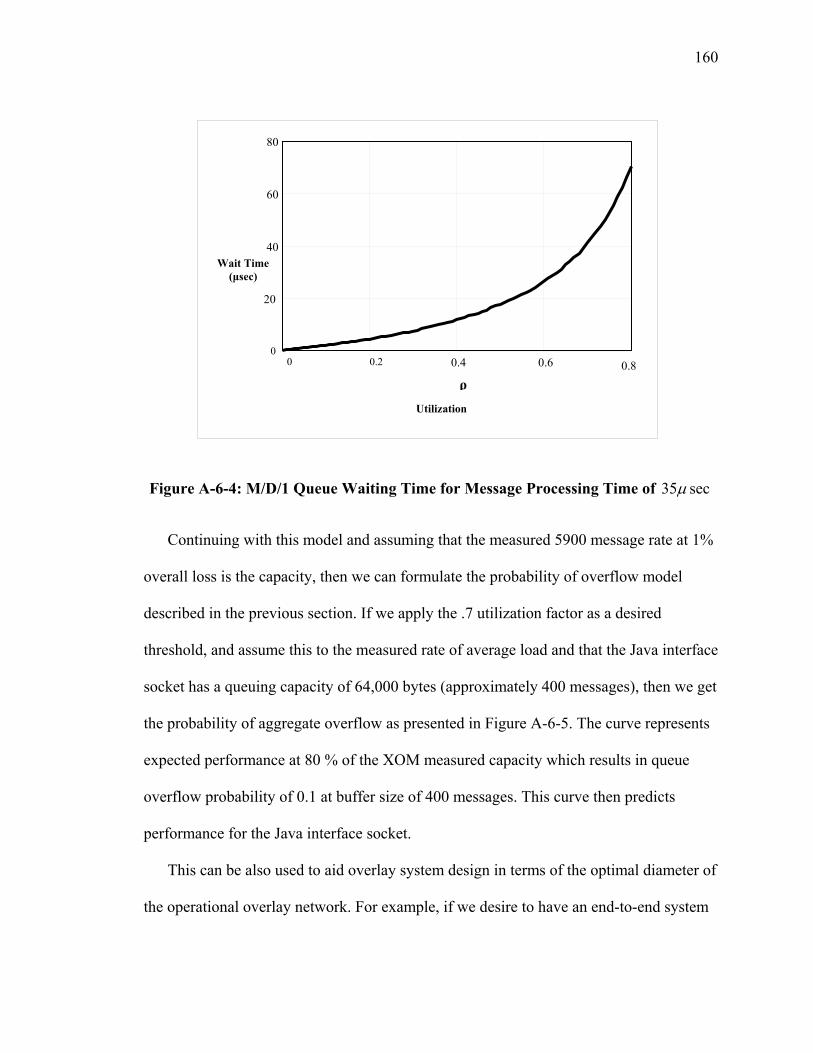
160
Figure A-6-4: M/D/1 Queue Waiting Time for Message Processing Time of 35 secµ
Continuing with this model and assuming that the measured 5900 message rate at 1%
overall loss is the capacity, then we can formulate the probability of overflow model
described in the previous section. If we apply the .7 utilization factor as a desired
threshold, and assume this to the measured rate of average load and that the Java interface
socket has a queuing capacity of 64,000 bytes (approximately 400 messages), then we get
the probability of aggregate overflow as presented in Figure A-6-5. The curve represents
expected performance at 80 % of the XOM measured capacity which results in queue
overflow probability of 0.1 at buffer size of 400 messages. This curve then predicts
performance for the Java interface socket.
This can be also used to aid overlay system design in terms of the optimal diameter of
the operational overlay network. For example, if we desire to have an end-to-end system
0 0.2 0.4 0.6 0.8 0
20
40
60
80
Utilization
Wait Time (µsec)
ρ
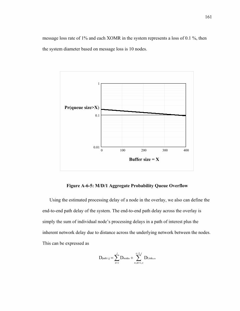
161
message loss rate of 1% and each XOMR in the system represents a loss of 0.1 %, then
the system diameter based on message loss is 10 nodes.
Figure A-6-5: M/D/1 Aggregate Probability Queue Overflow
Using the estimated processing delay of a node in the overlay, we also can define the
end-to-end path delay of the system. The end-to-end path delay across the overlay is
simply the sum of individual node’s processing delays in a path of interest plus the
inherent network delay due to distance across the underlying network between the nodes.
This can be expressed as
n n,m
1,
path i,j node Link
, ,
D D Dj x j
n i n m i x
−
= =
= +∑ ∑
0 100 200 300 4000.01
0.1
1
Buffer size = X
Pr(queue size>X)
162
where n,m represent the end nodes of the links along the path from i to j. The first
summation is the processing delay at each node along the path and the second summation
is the link delay between the nodes along the path.
This part of section 6 has presented results of performance testing of the XOM
prototype. Included were traffic loading tests using a 4-subnet and a 2 subnet test
scenarios. These tests were used to find the point of traffic load where the XOM message
loss ratio exceeds 1%. Based on study of a single message arrival and the closely spaced
arrival of a second message, measurements were made of the XOM processing time for
replication of messages. These measurements were used to estimate what might be
possible for throughput performance in an optimal XOM solution. There are two
important results from this section. The first is the observation of importance node
degree, or the number of message replications required of the XOM for arriving
messages, to the overall performance of the XOM. The second is that the measured
performance of the XOM can be related to the proposed analytical model of Section 5. In
the next part of this section, these results are used to describe key features of the
proposed architecture for the optimal XOM.
III Architecture Considerations
There are many important considerations in the overall design of the XOM that result
from the study of the live simulations and the laboratory testing of the prototype. In this
part of section 6, the most important of these are presented in relationship to the proposed
architecture. This section presented results of laboratory testing of the prototype to
163
analyze throughput performance and establish the relationship to the analytical model
developed in the previous section. The results lead directly to design considerations for
end-to-end performance of the overlay. In addition, Section 4 provided insight to the
behavior of live simulations that also impact the design. The most important of these are
that the message flow is represented by ON/OFF traffic pattern where OFF means a
lower rate, never zero, and the message sizes tend to be of fixed length. These
considerations are important for XOM to support efficient, reliable many-to-many
multicast transmissions over existing network protocols used across open networks.
The XOM must provide real-time response and predictable network services in order
for the end simulation systems to interact within specific delay bounds. In the overlay
concept, the overly protocol host only has control of its own performance and allocation
of local resources and does not have an ability to influence the services of the underlying
network. In the previous section, we describe what the limits of capacity are in terms of
throughput and packet loss. Both of these parameters are measurable locally and reflect
the local capacity. The current prototype now includes a statistics module that captures
this data and makes it available for viewing using Web services. The approach not only
allows viewing of the local host XOMR performance, but a feature allows viewing of
other XOMRs performance in the overlay. Essentially, the near real-time performance of
all XOMRs is available for use in performance optimization of the overlay.
This section defined the throughput and loss ratio in terms of n-degree where degree
means the number of replicated messages that an XOMR might be required to make
given the topology of the overlay. Using the measurement capability of the XOMR, it is
164
then possible to use the information to define performance in terms of n-degree. The local
XOMR then can make decisions about its role in the overall overlay. For example, the
XOMR can implement a decision process that says it is able or unable to support a relay
function between XOMRs or accept a new relay function given the current n-degree of
the node. The XOMR also could use the information to accept or deny new traffic flows
from the local subnet or offer a reduce service with less performance guarantees. The
idea is to maximize available capacity in the overlay. This is consistent with the proposed
approach for the XOMR, where each XOMR is essentially a proxy agent that has the
ability to replicate messages and forward to the appropriate local host or other XOMR
node in the overlay.
There are at least two possible alternatives to use this information for construction
and management for the overlay. The first is to implement a two-step construction
process similar to the Scattercast protocol described in Section 3 and the second is to add
a parameter to the current prototype implementation of Dijkstra’s algorithm that reflects
the ability or willingness of an XOMR to support additional capacity in support of the
overlay network.
Recall that Scattercast uses a two step process to build the overlay. It first builds a
mesh of nodes randomly and is able periodically to locate the best nearest neighbor if
there is one better than the current. Scattercast then runs a distance vector algorithm to
form a minimum routing tree.
The second alternative is to take advantage of the current prototype use of Dijkstra’s
algorithm directly by adding a constraint for degree. The current implementation builds a
165
distribution tree given known other XOMRs in the overlay. Information about other
nodes is obtained by XOMRs exchanging information. Implementation of a registry is
part of the proposed architecture and will provide services to assist this process in the
future. An attractive concept would be to modify Dijkstra’s algorithm to include an index
for the XOMR’s degree or capacity to increase degree. Kwon [Kwon02] provides an
outline of an algorithm that could be modified to perform this function. Boehm [Boeh02]
developed a variation of Dijkstra’s algorithm for constraint routing, using heuristics to
reduce computational complexity.
The second key observation is that the arrival process is representative of ON/OFF
and never zero with messages sizes deterministic in nature. The previous section
demonstrated that this can be represented analytically as an M/D/1 queue model. The
implication is that we expect better performance of the queueing mechanism than if the
messages size where exponentially distributed. In fact, the M/D/1 queuing system has
2
2 (1 )ρ
ρ∗ − fewer messages in the system than the M/M/1 queuing system [Klei75]. This
means that we should be able to operate the XOMR with higher queue threshold values
for the same throughput than might be available if the XOMR where an open network
router or lower layer service router. However, if operating at a higher threshold, then, a
mechanism to handle bursts of messages may be required.
There are two possible approaches to handle higher arrival rates or bursts. Both
approaches are included in the proposed architecture. The first is to use a protocol like the
Selectively Reliable Protocol (SRMP) as an interface to the XOMR and the second is to
166
implement a priority queueing mechanism and offer two classes of service; Class B with
no priority and Class A with priority.
While the SRMP is designed to offer a selectively reliable service, it in effect serves
to function as a flow control mechanism by giving a higher grade of service to messages
that are marked for higher reliability. For the case of two class queuing, the service gives
priority to the higher class when congestion occurs. The lower class messages are
dropped if the queue overflows.
IV Summary
The design of the architecture is focused on meeting the many-to-many multicast
service requirement of distributed simulations with high confidence in the service
performance. This Section has related key aspects from the observation of live
simulations and key performance characteristics of the current prototype to architecture
design considerations. Included was development of a link between the proposed
analytical model and evaluation of an early prototype of the XOM overlay. The purpose
is to validate the analytical model and serve to form a basis of key features in the
proposed architecture.
Part II of this section presented the results of laboratory tests of the current XOMR
prototype conducted in the GMU C3I Laboratory and related key measurements to the
concept of a node degree where degree means the number of message replications are to
be performed for an arriving message. Part III discussed key aspects of the proposed

167
architecture that were influenced by results from laboratory tests as well as from the
study of live simulations.
168
SECTION 7 CONCLUSIONS, CONTRIBUTIONS, AND RECOMMENDATIONS FOR FUTURE RESEARCH
I Introduction
Many-to-many multicast transmission is an essential network capability for
distributed real-time virtual simulation. However, many open issues make network-layer
multicast impractical over the Internet leading to consideration of alternative strategies to
support the distributed real-time simulation application environment. Previous sections
developed a description of the problem, proposed an alternative strategy and provided
evidence to support the conclusion that it is feasible to provide multicast services for the
environment based on the concept of a network overlay. This section discusses the
conclusions of the research and summarizes the unique contributions that resulted from
the work. The section concludes with recommendations for future research that can serve
to extend this effort.
II Conclusions
This research has demonstrated that it is feasible for host-based or end system overlay
multicast to provide multicast services to real-time distributed simulation across an open
network. The results further indicate that implementing an overlay multicast strategy
allows the distributed simulation environment to maintain some independence of the
169
underlying network services thus allowing use of lower layer Internet protocols. To
demonstrate the feasibility, the following items were accomplished:
• Detailed studies were conducted of three live simulations. The simulation
environments where analyzed by using OPNET Modeler where actual traces of
message behavior was captured and used to characterize the requirements for
overlay multicast performance. These studies provided the baseline for
comparison of expected performance for the overlay approach.
• A message traffic load generator was implemented based on the results of the
simulation studies and used as the control load for laboratory studies of overlay
system performance.
• An analytical model was developed to aid in the understanding of system
behavior and providing a statistical basis for predicting performance. The model
was validated by comparison to message load studies in the laboratory using
OPNET Modeler analysis tools for data capture.
• Using the message traffic generator and an overlay multicast protocol prototype,
detailed performance studies where conducted in a laboratory with various
network configurations across open network Internet protocols. These studies
were used to validate the analytical model and form the basis for predicting
expected performance of an operational overlay multicast protocol.
170
III Unique Contributions of this Research
The conceptual development and demonstration of the fundamentals for a host-based
multicast protocol represents an important contribution to knowledge of how best to
support many-to-many communications for real-time distributed virtual simulations in an
open network. The research demonstrated the power of the overlay approach for
providing networking flexibility for real-time distributed simulations by enabling users of
these applications to network without the need for costly private networking. This
approach helps to expand the real-time distributed simulation user base since the concept
could extend to individual personal computers (PCs) acting as relay nodes, enabling low-
cost end-to-end multicast schema.
The research addressed the issue of scaling the performance of the overlay. A
methodology was defined and demonstrated for studying the effects of scaling based on
the idea of node degree where degree means the number of replicated messages or
channels to neighboring overlay nodes. The application of this idea forms the basis for
defining a capacity of an overlay node in simple terms that can be used by a routing
algorithm in the dynamic formation of an overlay network.
The research made a unique contribution in the characterization of message load
generated by real-time virtual distributed simulations. Three live simulations were
studied which resulted in detail characterization at the simulation federate level as well as
the aggregated flow of message traffic in a very large simulation with 110, 000 federates
operating across a private network built over the DREN.
171
The results of these studies enabled the formulation of an analytical model to describe
the environment. This was a significant contribution as this model provides a statistically
relevant model that can be directly used for managing and deploying many-to-many
overlay multicast network. The analytical model provides the ability to forecast expected
performance based on real-time measurement of aggregated message flow through an
overlay node.
The primary outcome of this research was to develop a high level architecture of a
proposed overlay multicast protocol that would provide many-to-many multicast services
for real-time distributed virtual simulation. This architecture was developed based on
results of the traffic studies of live simulations and the subsequent development of
analytical model as well as prototype testing in the laboratory. The proposed architecture
recognizes that underlying networks may have a wide range of network capacities and
capabilities yet provides a multicast service to higher layer applications that require this
capability across open networks. The proposed approach includes consideration for
reliability by providing two classes of services such that the application may specify
message handling a under congested network conditions.
IV Recommendations for Future Research
The original purpose of this research was to validate and demonstrate the feasibility
of using overlay multicast to support a very demanding communications requirement.
The outcomes of the current research have provided confidence that the approach is valid.
As the work moves to the next level in experiments and development, it is clear that there
172
are many challenges remaining. Research focus should continue to be on efficiency and
scalability as well as overlay management mechanisms that respond to the dynamic
nature of underlying open networks as well as the dynamic nature of the application
environment. The next steps for consideration in continuing the work are:
• Validate the approach by using the prototype in a live wide area network
simulation requiring performance levels that stress the capabilities of the XOMR.
• Establish a testing environment where evaluation of specific routing algorithms
can be performed. The results of this testing will refine the routing features of the
overlay and provide for improved optimization of overlay network performance.
• Research and add security features to the prototype for protection from denial of
service attacks and related intrusions and implementation of capabilities to
support end-to-end information protection features.
• The current prototype employs services over UDP. This should be expanded to
include a concept of TCP tunnels for improved security and for those applications
that have streaming data that desire more reliability than UDP. The study of TCP
should include how to manage the slow start feature of TCP so as not to hinder
performance.
• Continue refining the protocol by prototyping repeatedly at increasing levels of
sophistication and optimization.
• Refine and continue integration with early prototypes of web-services used in
distributed real-time simulations.

173
• Research and prototype registry services for the overlay as part of an over all
improvement in overlay management capabilities.
• Research and prototype the ability to provide for two priority classes, “priority”
and “best effort,” in cases where aggregate application throughput requirements
are at or above the capacity provided by the underlying network.
• Research how an overlay multicast protocol could take advantage of commercial
efforts to improve underlying network QoS and use services such as
Multiprotocol Label Switching (MPLS).
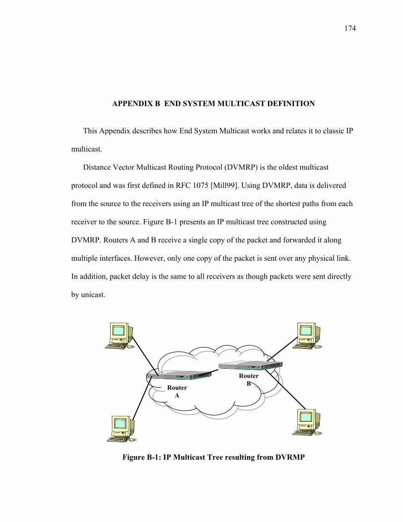
174
APPENDIX B END SYSTEM MULTICAST DEFINITION
This Appendix describes how End System Multicast works and relates it to classic IP
multicast.
Distance Vector Multicast Routing Protocol (DVMRP) is the oldest multicast
protocol and was first defined in RFC 1075 [Mill99]. Using DVMRP, data is delivered
from the source to the receivers using an IP multicast tree of the shortest paths from each
receiver to the source. Figure B-1 presents an IP multicast tree constructed using
DVMRP. Routers A and B receive a single copy of the packet and forwarded it along
multiple interfaces. However, only one copy of the packet is sent over any physical link.
In addition, packet delay is the same to all receivers as though packets were sent directly
by unicast.
Figure B-1: IP Multicast Tree resulting from DVRMP
Router A
Router B
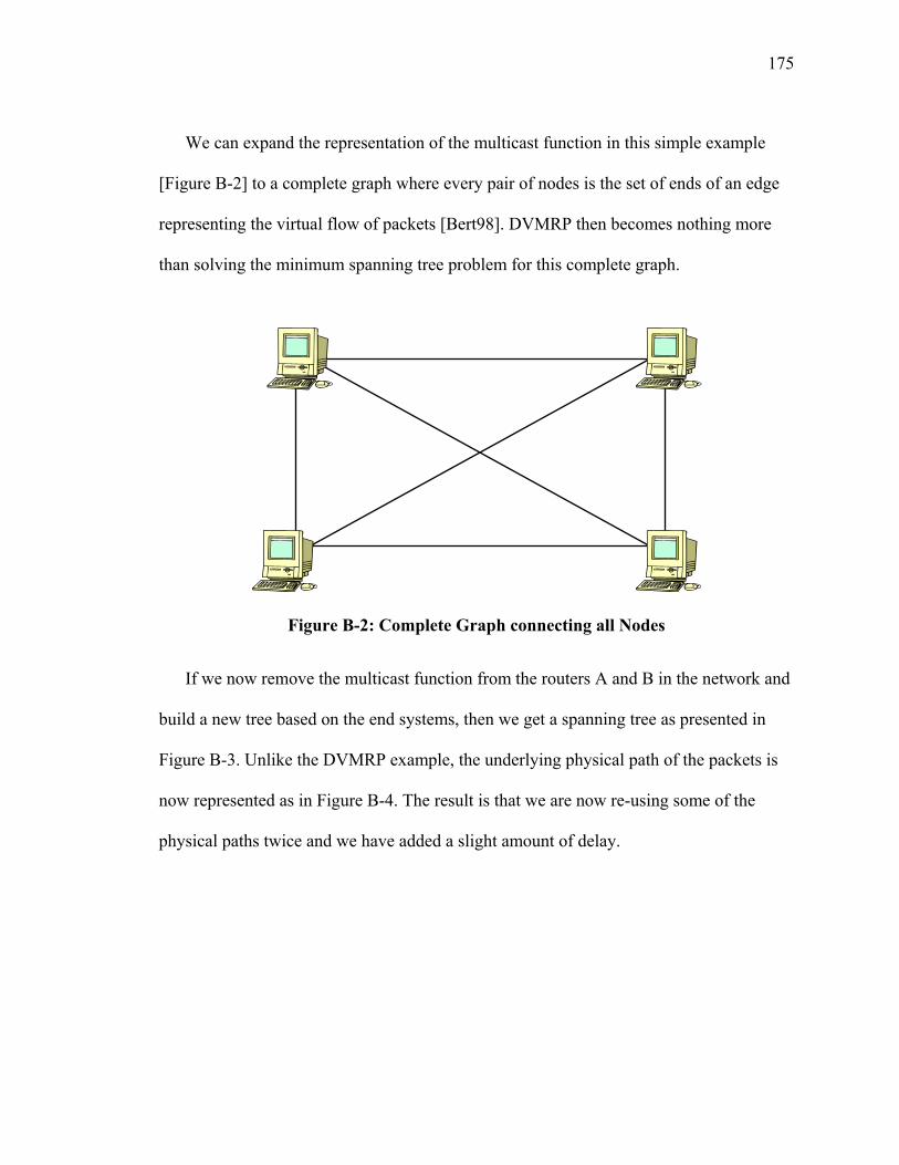
175
We can expand the representation of the multicast function in this simple example
[Figure B-2] to a complete graph where every pair of nodes is the set of ends of an edge
representing the virtual flow of packets [Bert98]. DVMRP then becomes nothing more
than solving the minimum spanning tree problem for this complete graph.
Figure B-2: Complete Graph connecting all Nodes
If we now remove the multicast function from the routers A and B in the network and
build a new tree based on the end systems, then we get a spanning tree as presented in
Figure B-3. Unlike the DVMRP example, the underlying physical path of the packets is
now represented as in Figure B-4. The result is that we are now re-using some of the
physical paths twice and we have added a slight amount of delay.
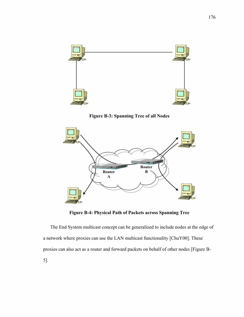
176
Figure B-3: Spanning Tree of all Nodes
Figure B-4: Physical Path of Packets across Spanning Tree
The End System multicast concept can be generalized to include nodes at the edge of
a network where proxies can use the LAN multicast functionality [ChuY00]. These
proxies can also act as a router and forward packets on behalf of other nodes [Figure B-
5].
Router A
Router B
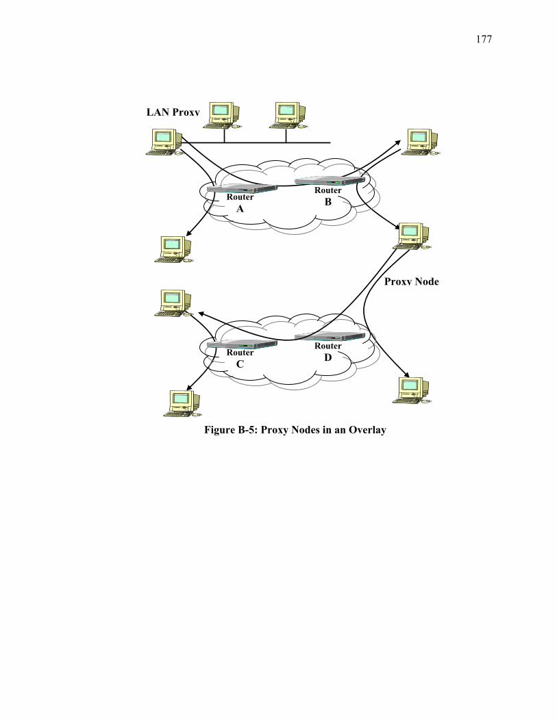
177
Figure B-5: Proxy Nodes in an Overlay
Router C
Router D
Router A
Router B
Proxy Node
LAN Proxy
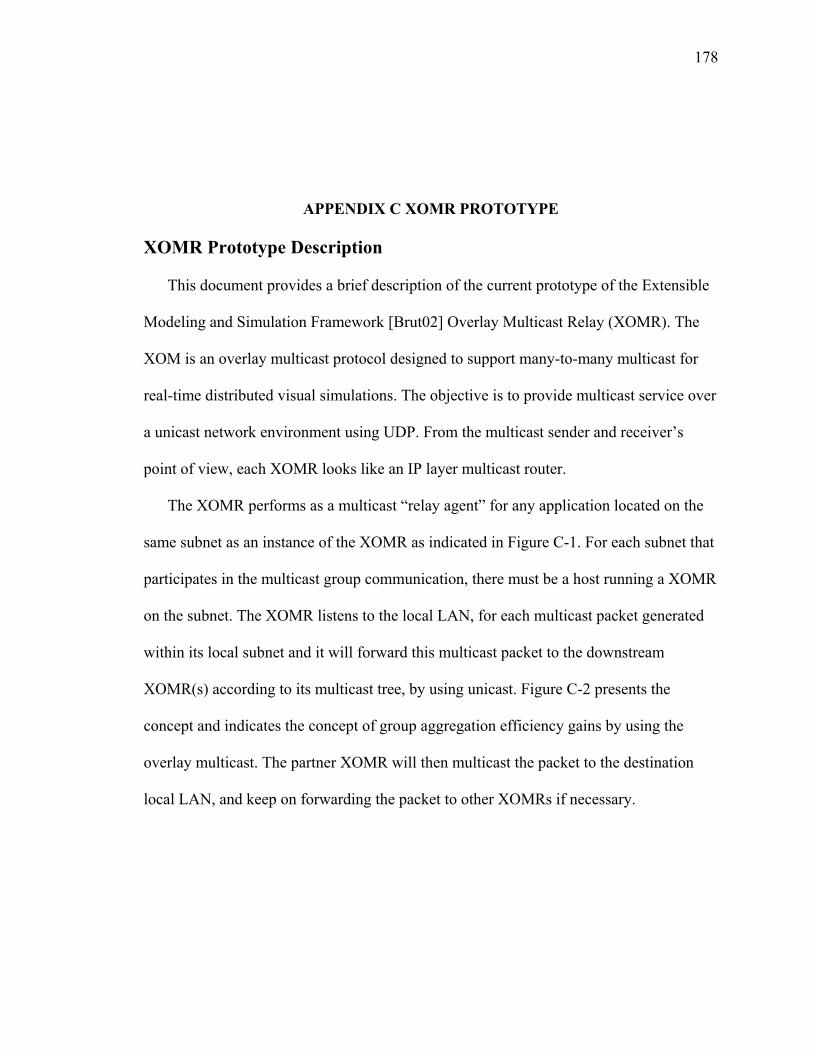
178
APPENDIX C XOMR PROTOTYPE XOMR Prototype Description
This document provides a brief description of the current prototype of the Extensible
Modeling and Simulation Framework [Brut02] Overlay Multicast Relay (XOMR). The
XOM is an overlay multicast protocol designed to support many-to-many multicast for
real-time distributed visual simulations. The objective is to provide multicast service over
a unicast network environment using UDP. From the multicast sender and receiver’s
point of view, each XOMR looks like an IP layer multicast router.
The XOMR performs as a multicast “relay agent” for any application located on the
same subnet as an instance of the XOMR as indicated in Figure C-1. For each subnet that
participates in the multicast group communication, there must be a host running a XOMR
on the subnet. The XOMR listens to the local LAN, for each multicast packet generated
within its local subnet and it will forward this multicast packet to the downstream
XOMR(s) according to its multicast tree, by using unicast. Figure C-2 presents the
concept and indicates the concept of group aggregation efficiency gains by using the
overlay multicast. The partner XOMR will then multicast the packet to the destination
local LAN, and keep on forwarding the packet to other XOMRs if necessary.
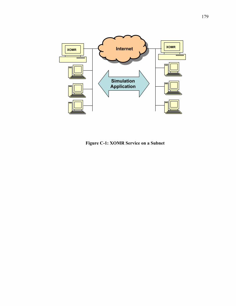
179
Figure C-1: XOMR Service on a Subnet
Internet XOMR XOMR
Simulation Application
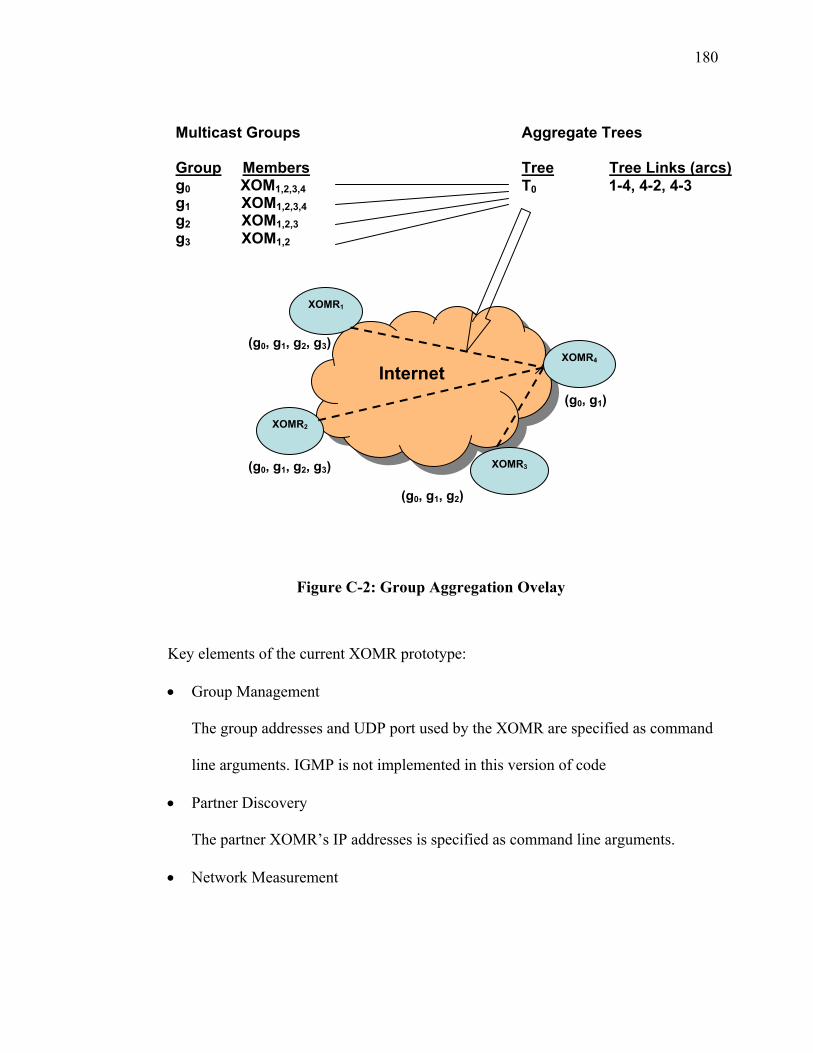
180
Figure C-2: Group Aggregation Ovelay
Key elements of the current XOMR prototype:
• Group Management
The group addresses and UDP port used by the XOMR are specified as command
line arguments. IGMP is not implemented in this version of code
• Partner Discovery
The partner XOMR’s IP addresses is specified as command line arguments.
• Network Measurement
Multicast Groups Group Members g0 XOM1,2,3,4 g1 XOM1,2,3,4 g2 XOM1,2,3 g3 XOM1,2
Aggregate Trees Tree Tree Links (arcs) T0 1-4, 4-2, 4-3
XOMR2
XOMR4
XOMR3
XOMR1
Internet
(g0, g1, g2, g3)
(g0, g1)
(g0, g1, g2)
(g0, g1, g2, g3)
181
XOM uses delay as the routing metric. A virtual mesh composed of all the
XOMRs is established. This mesh is a concept of the transport layer. The current
version establishes a full mesh, and every XOMR maintains this mesh topology in
a matrix that also includes the measured network delay between XOMRs.
Each XOMR periodically sends Ping message to all partner XOMRs it knows.
Each XOMR will echo Ping messages received from other XOMRs and use the
response to measure round trip times RTT) as the measure for delay. Periodically,
each XOMR will flood its measured RTT values to all its XOMR partners. At
last, every XOMR will keep a delay matrix of RTT value between every two
XOMs.
• Multicast Forwarding Tree calculation
Periodically, each XOMR will calculate a source specific multicast tree according
to its delay matrix. The tree is rooted at the source XOMR. The prototype uses
Shortest Path First (SPF) tree algorithm.
• Routing Update
Periodically, each XOMR will flood its multicast tree to all other partner XOMRs.
Each XOMR will keep n multicast trees, where n equals to the total number of
XOMRs.
• Packet replicating and Forwarding
When a XOMR receives a multicast data packet from its local LAN, it will
encapsulate it, replicate it, and forward it to the downstream neighbors according
to its own multicast tree. When a XOMR receives a UDP data packet from

182
another XOMR, it will check to see from which source XOMR the UDP packet
was originally generated (but not the upstream neighbor). It then checks the
locally stored multicast trees for that source XOMR to replicate the packet and
forward it to other downstream XOMRs if there is any. Meanwhile, the XOMR
will de-capsulate the UDP packet and multicast it to its local LAN.
Prototype Software Design
The XOMR was first implemented in JAVA. Then, to improve the performance, the
Packet replicating and forwarding modules were implemented in C++. The control
module remains implemented in Java. The JAVA and C++ modules were integrated
by using Java JNI callback.
Figure C-3. presents the design structure of the JAVA version XOMR
implementation. The JAVA version is composed of the following four major classes:
• public class XOM; This is the main class and creates all the threads and
initializes the data structures. This class also provides general methods and
auxiliary functions, such as network layer address format conversion,
encoding and decoding, searching, etc.
• public class XOMMulticastRouter extends Object implements Runnable;This
is the forwarding engine. This class replicates and forwards the packets. It
listens to both the local LAN and other XOMRs. It stores the forwarding table

183
in its member variable XOMMulticastRouter.forwardingTables: The
forwarding table is periodically updated by class XOMRoutingTable.
• public class XOMRoutingTable implements Runnable;This class performs the
real routing work. It processes the delay information and multicast tree
information received from other XOMRs. It then calculates its own multicast
tree according to this information, and updates the forwarding table in class
XOMMulticastRouter:
• public class XOMStatistics implements Runnable; This class measures the
RTT values to all the other XOMRs. It also does the statistics work, such as
total number of packets sent and received.
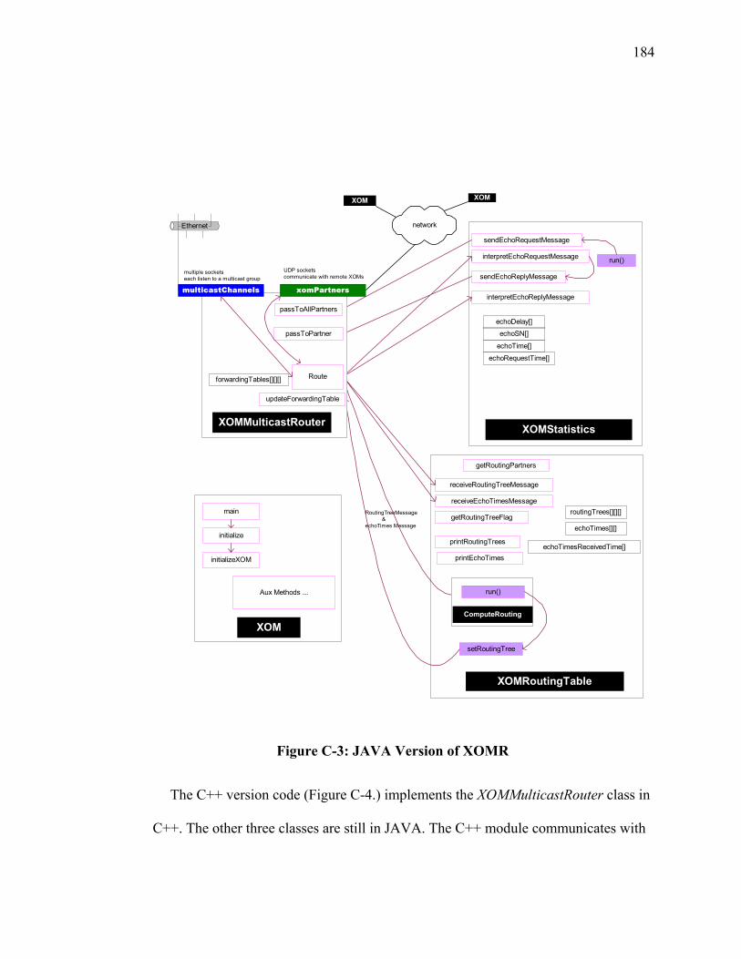
184
RoutingTreeMessage &echoTimes Message
XOMStatistics
interpretEchoRequestMessage
interpretEchoReplyMessage
sendEchoRequestMessage
echoDelay[]
echoSN[]
echoTime[]
echoRequestTime[]
sendEchoReplyMessage
run()
XOMRoutingTable
getRoutingPartners
receiveRoutingTreeMessage
receiveEchoTimesMessage
printRoutingTrees
routingTrees[][][]
echoTimes[][]
echoTimesReceivedTime[]
getRoutingTreeFlag
printEchoTimes
setRoutingTree
ComputeRouting
run()
XOM
initialize
main
initializeXOM
Aux Methods ...
networkEthernet
XOM XOM
XOMMulticastRouter
multicastChannels xomPartners
multiple socketseach listen to a multicast group
UDP socketscommunicate with remote XOMs
passToPartner
Route
passToAllPartners
forwardingTables[][][]
updateForwardingTable
Figure C-3: JAVA Version of XOMR
The C++ version code (Figure C-4.) implements the XOMMulticastRouter class in
C++. The other three classes are still in JAVA. The C++ module communicates with

185
the JAVA module by using JNI (Java Native Interface). All the data packets are
processed within the C++ module, which includes sending/receiving,
encapsulation/de-capsulation, and forwarding. All the control messages are passed to
the JAVA module. The C++ module keeps a forwarding table, which is updated by
the JAVA module. The following diagram shows the C++ version design structure:
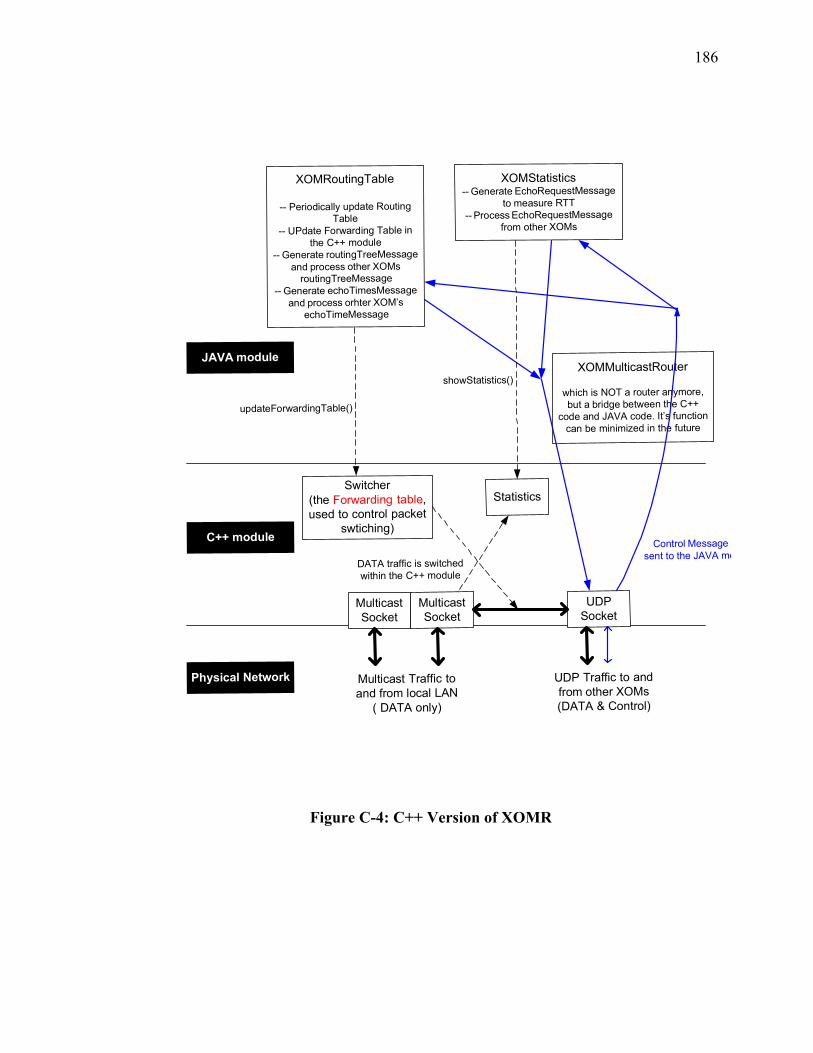
186
MulticastSocket
MulticastSocket
UDPSocket
Multicast Traffic toand from local LAN
( DATA only)
UDP Traffic to andfrom other XOMs(DATA & Control)
Switcher(the Forwarding table,used to control packet
swtiching)
DATA traffic is switchedwithin the C++ module
XOMMulticastRouter
which is NOT a router anymore,but a bridge between the C++
code and JAVA code. It’s functioncan be minimized in the future
XOMRoutingTable
-- Periodically update RoutingTable
-- UPdate Forwarding Table inthe C++ module
-- Generate routingTreeMessageand process other XOMs
routingTreeMessage-- Generate echoTimesMessage
and process orhter XOM’sechoTimeMessage
XOMStatistics-- Generate EchoRequestMessage
to measure RTT-- Process EchoRequestMessage
from other XOMs
Control Message sent to the JAVA mo
updateForwardingTable()
Statistics
showStatistics()
JAVA module
C++ module
Physical Network
Figure C-4: C++ Version of XOMR
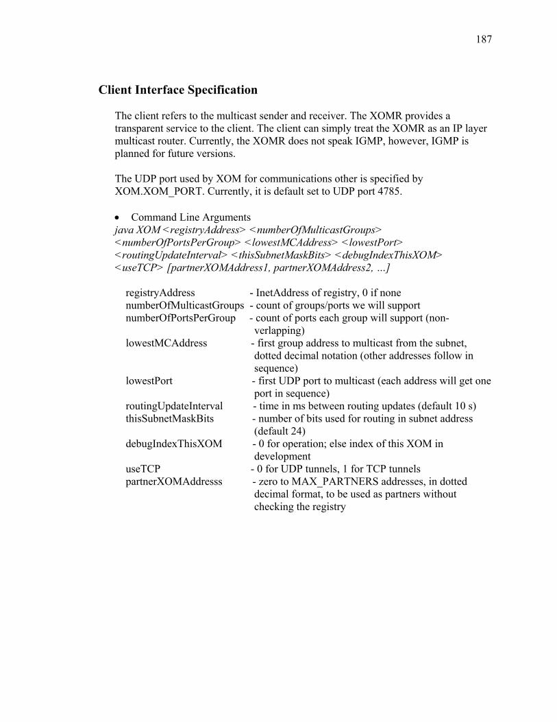
187
Client Interface Specification The client refers to the multicast sender and receiver. The XOMR provides a transparent service to the client. The client can simply treat the XOMR as an IP layer multicast router. Currently, the XOMR does not speak IGMP, however, IGMP is planned for future versions. The UDP port used by XOM for communications other is specified by XOM.XOM_PORT. Currently, it is default set to UDP port 4785. • Command Line Arguments java XOM <registryAddress> <numberOfMulticastGroups> <numberOfPortsPerGroup> <lowestMCAddress> <lowestPort> <routingUpdateInterval> <thisSubnetMaskBits> <debugIndexThisXOM> <useTCP> [partnerXOMAddress1, partnerXOMAddress2, …] registryAddress - InetAddress of registry, 0 if none numberOfMulticastGroups - count of groups/ports we will support numberOfPortsPerGroup - count of ports each group will support (non-
verlapping) lowestMCAddress - first group address to multicast from the subnet,
dotted decimal notation (other addresses follow in sequence)
lowestPort - first UDP port to multicast (each address will get one port in sequence)
routingUpdateInterval - time in ms between routing updates (default 10 s) thisSubnetMaskBits - number of bits used for routing in subnet address
(default 24) debugIndexThisXOM - 0 for operation; else index of this XOM in
development useTCP - 0 for UDP tunnels, 1 for TCP tunnels partnerXOMAddresss - zero to MAX_PARTNERS addresses, in dotted
decimal format, to be used as partners without checking the registry

188
Packet Format • DATA:
0 8 16 24 32 VERSION TYPE HOPS_TO_LIVE LEN
SOURCE_XOM_ADDRESS SENDER_ADDRESS
MULTICAST_ADDRESS UDP_PORT
VERSION: 8 bits, 0x 2 TYPE: 4 bits, 0x 1 HOPS_TO_LIVE: 4 bits, the number of hops can be relayed by XOMs LEN: 16bits, the packet length including the header SOURCE_XOM_ADDRESSS: 32bits, the IPv4 address of the XOM that generate this UDP packet SENDER_ADDRESS: 32bits, the IPv4 address of the end host that generate the multicast packet MULTICAST_ADDRESS: 32bits, the multicast address used by the end host UDP_PORT: 16 bits, the UDP port used by the end host • ROUTING_TREE:
0 8 16 24 32 VERSION TYPE HOPS_TO_LIVE LEN
SOURCE_XOM_ADDRESS NUMBER_OF_ROWS ROW_ENTRIES (Variable Length)
For Each ROW_ENTRY:
PARTNER_XOM_ADDRESS NUMBER_OF_COLUMNS COLUMN_ENTRIES (Variable Length)
For Each COLUMN_ENTRY:
TARGET_XOM_ADDRESS VERSION: 8 bits, 0x 2 TYPE: 4 bits, 0x 2 HOPS_TO_LIVE: 4 bits, the number of hops can be relayed by XOMs LEN: 16bits, the packet length including the header SOURCE_XOM_ADDRESSS: 32bits, the IPv4 address of the XOM that generate this routing information NUMBER_OF_ROWS: 16bits, the number of rows of the routing_tree matrix ROW_ENTRIES: variable lengths, may be composed of multiple ROW_ENTRYs PARTNER_XOM_ADDRESS: 32 bits, the IPv4 address of the XOM corresponding to the row NUMBER_OF_COLLUMNS: 16 bits, number of downstream partner XOMs COLUMN_ENTRIES: variable length, may be composed of multiple TARGET_XOM_ADDRESS TARGET_XOM_ADDRESS: 32 bits, the IPv4 address of the downstream XOM • ECHO_TIMES:
0 8 16 24 32 VERSION TYPE HOPS_TO_LIVE LEN
SOURCE_XOM_ADDRESS NUMBER_OF_ENTRIES ENTRIES (Variable Length)
For Each Entry:
TARGET_XOM_ADDRESS ECHO_TIME VERSION: 8 bits, 0x 2 TYPE: 4 bits, 0x 3 HOPS_TO_LIVE: 4 bits, the number of hops can be relayed by XOMs

189
LEN: 16bits, the packet length including the header SOURCE_XOM_ADDRESSS: 32bits, the IPv4 address of the XOM that generate this echo time list NUMBER_OF_ENTRIES: 16 bits, the number of entries in the echo time list ENTRIES: variable length, may be composed of multiple entries TARGET_XOM_ADDRESS: the IPv4 address of the target XOM ECHO_TIME: the RTT value between the SOURCE_XOM_ADDRESS and TARGET_XOM_ADDRESS • ECHO_REQUEST:
0 8 16 24 32 VERSION TYPE HOPS_TO_LIVE LEN
SOURCE_XOM_ADDRESS RESERVED SN
VERSION: 8 bits, 0x 2 TYPE: 4 bits, 0x 4 HOPS_TO_LIVE: 4 bits, the number of hops can be relayed by XOMs LEN: 16bits, the packet length including the header, always equals to 0x12 SOURCE_XOM_ADDRESSS: 32bits, the IPv4 address of the XOM that generate this echo request RESERVED: 24 bits SN: 8 bits • ECHO_REPLY:
0 8 16 24 32 VERSION TYPE HOPS_TO_LIVE LEN
SOURCE_XOM_ADDRESS RESERVED SN
VERSION: 8 bits, 0x 2 TYPE: 4 bits, 0x 5 HOPS_TO_LIVE: 4 bits, the number of hops can be relayed by XOMs LEN: 16bits, the packet length including the header, always equals to 0x12 SOURCE_XOM_ADDRESSS: 32bits, the IPv4 address of the XOM that generate this echo reply RESERVED: 24 bits SN: 8 bits
190
REFERENCES [Bane03] Banerjee, Suman, Christopher Kommareddy, Koushik Kar, Bobby
Bhattacharjee, and Samir Khuller, “Construction of an Efficient Overlay Multicast Infrastructure for Real-time Applications,” IEEE 2003, pp. 1521-1531.
[Baue95] Bauer, F., and A. Varma, "Degree-Constrained Multicasting in Point-to-
Point Networks," IEEE INFOCOM, Apr 1995, pp. 369-376. [Baue96] Bauer, Fred, and Anujan Varma, "Distributed Algorithms for Multicast
Path Setup in Data Networks," IEEE/ACM Transactions on Networking, Vol. 4, No. 2, April 1996, pp. 181-191.
[Bert98] Bertsekas, Dimitri P., Network Optimization: Continuous and Discrete
Models, Athena Scientific, Belmont, Mass., 1998. [Bhat03] Bhattacharyya, S., “An Overview of Source-Specific Multicast,” IETF
RFC 3569, 2003. [Bian00] Bianchi, Giuseppe, Antonio Capone, and Chiara Petrioli, “Throughput
Analysis of End-to-End Measurement-Based Admission Control in IP,” Proc. IEEE INFOCOM ’00, 2000, pp. 1461-1470.
[Boeh02] Boehm, Douglas W., "An Investigation of Negotiations of Quality of
Service (QoS) Parameters in a Connection-Oriented Telecommunications Network Environment,” Ph.D. Dissertation, George Mason University, 2002.
[Boll01] Bollobas, Bela, Random Graphs, 2nd Edition, Cambridge Press, NY,
2001. [Brau93] Braudes, R. and S. Zabele, “Requirements for Multicast Protocols,” IETF
RFC 1458, 1993. [Brut02] Brutzman, D., M. Zyda, M., J.M. Pullen, and K.L. Morse, “Extensible
Modeling and Simulation Framework (XMSF): Challenges for Web-Based Modeling and Simulation,” US Naval Postgraduate School, 2002.
191
[Cain02] Cain, B., S. Deering, I. Kouvelas, B. Fenner, A. Thyagarajan, “Internet
Group Management Protocol, Version 3,” IETF RFC 3376, 2002. [Cast02] Castro, Miguel Peter Druschel, Anne-Marie Kermarrec, and Antony I. T.
Rowstron “Scribe: A Large-Scale and Decentralized Application-Level Multicast Infrastructure,” IEEE Journal On Selected Areas In Communications, Vol. 20, No. 8, October 2002, pp. 1489-1499.
[CastUK] Castro, Miguel, "Scalable Application-Level Anycast for Highly Dynamic
Groups," Microsoft Research, Cambridge, CB3 OFB, UK. [Chen00] Chen, Shigang, Klara Nahrstedt, and Yuval Shavitt, "A QoS-Aware
Multicast routing Protocol," IEEE Journal on Selected Areas in Communications, Vol. 18, No.12, December 2000, pp. 2580-2592.
[ChuU00] Chu, Uang-hus, Sanjay G. Rao, and Hui Zhang, “ A Case for End System
Multicast,” ACM SIGMETRICS 2000, pp. 1-12. [ChuY01] Chu, Yang-hua, S. G. Rao, S. Seshan, and H. Zhang, “Enabling
Conferencing Applications on the Internet using an Overlay Multicast Architecture,” Proceedings of ACM, SIGCOMM2001, August 2001, pp. 55-67.
[ChuY00] Chu, Yang-hua, S. G. Rao, S. Seshan, and H. Zhang, “A Case for End
System Multicast,” Proceedings of the ACM Sigmetrics, June 2000. [Corm97] Corman, T. H., C. E. Leiserson, and R. L. Rivest, Introduction to
Algorithms, MIT Press, MA, 1997 [CuiJ04] Cui, Jun-Hong, Michalis Faloutsos and Mario Gerla, “An Architecture for
Scalable, Efficient, and Fast Fault-Tolerant Multicast Provisioning,” IEEE Network Magazine , March/April 2004, pp. 26-34.
[CuiY04] Cui, Yi, Baochun Li and Klara Nahrestedt, “oStream: Asynchronous
Streaming Multicast in Application–Layer overlay Networks ,” IEEE Journal on Selected Areas in Communications, Vol. 22, No. 1, January 2004, pp.91-106.
[Deer90] Deering, Stephen E., and David R. Cheriton, “Multicast Routing in
Datagram Networks and Extended LANS,” ACM Transactions On Computer Systems, Vol. 18, No 2, May 1990, pp. 85-110.
192
[Diot97] Diot, Christophe, Walid Dabbous, and Jon Crowcroft, “Multipoint Communication: A Survey of Protocols, Functions, and Mechanisms,” IEEE Journal On Selected Areas In Communications, Vol. 15, No. 3, April 1997, pp. 277-290.
[Embr02] Embrechts, Paul, and Makoto Maejima, Self-similar Processes, Princeton
University Press, Princeton, N.J., 2002. [Erik94] Eriksson, H., "MBONE: The Multicast Backbone," Communications of
the ACM, Vol. 37, No. 8, 1994, pp. 54-60. [Erra96] Erramilli, Ashok, Onutttom Narayan, and Walter Willinger,
“Experimental Queueing Analysis with Long-Range Dependent Packet Trafic,” IEEE/ACM Transactions on Networking, Vol. 4, No. 2, April 1996, pp. 209-223.
[Estr98] Estrin, d., D. Farinacci, A. Helmy, D. Thaler, S. Deering, M. Handley, V.
Jacobson, C. Liu, P. Sharma, and L. Wei, "Protocol Independent Multicast-Sparse Mode (PIM-SM): Protocol Specification," IETF RFC 2362, June 1998.
[FeiA01] Fei, Aiguo, Zhihong Duan, and Mario Gerla, “Constructing Shared-Tree
For Group Multicast With QoS Constraints,” IEEE Global Telecommunications Conference, 2001,Vol. 4, Nov. 2001 pp. 2389 – 2394.
[Fisc93] Fischer, Wolfgang, and Kathleen Meier-Hellstern, "The Markov-
modulated Poisson Process (MMPP) Cookbook", Performance Evaluation, Vol. 18, Is. 2, September 1993, pp. 149-171.
[Floy62] Floyd, Robert W., " Algorithm 97: Shortest Path," Communications of the
ACM, Volume 5 Issue, June 1962, pp.344-348. [Floy99] Floyd, Sally, and Kevin Fall, “Promoting the Use of End-to-End
Congestion Control in the Internet,” IEEE/ACM Transactions on Networking, May 3, 1999, pp. 458-472.
[Fran00] Francis, Paul, "Yoid Tree Management Protocol (YTMP) Specification,"
ACIR Center for Internet Research, Berkeley, CA, April 2000. [Gall83] Gallager, R. G., P. A. Humblet, and P. M. Spira, "A Distributed
Algorithm for Minimum-Weight Spanning Trees,” ACM Transactions on Programming Languages and Systems, Vol. 5, No. 1, January 1983, pp. 66-77.
193
[Gros98] Gross, Donald, and Carl M. Harris, Fundamentals of Queueing Theory, Third Edition, John Wiley & Sons, New York, 1998.
[Heff86] Heffes, H., and D. Lucantoni, "A Markov Modulated Characterization of
Packetized Voice and Data Traffic and Related Statistical Multiplexer Performance," Selected Areas in Communications, IEEE Journal on, Volume 4, Issue 6, Sep 1986, pp. 856 – 868.
[Hype02] Hypercast Team, "Hypercast 2.0 Design Document,"
http://www.cs.virginia.edu/~hpercast, Department of Computer Science, University of Virginia, 2002.
[Huan03] IP Traffic Modeling (IPTM group), “Models for Traffic Generators,”
www.contel.it/projects/1ptm/index.html. [Huan03b] Huang, Jiaqing, Xu Du, Zongkai Yang, and Wenqing Cheng, “Available
Bandwidth-based Real-time Multicast Routing Distributed Algorithm,” Proceedings of the 2003 International Conference on Computer Networks and Mobile Computing (ICCNMC’03).
[Jann00] Jannotti, John, David K Giffors, Kirk L. Johnson, M. Frans Kasschoek,
James W. O’Toole, Jr. “Overcast: Reliable Multicasting with an Overlay Network,” 5th Symposium on Operating System Design and Implementation, 2000, Vol. III, pages 493-496.
[JiaX98] Jia, Xiaohua, "A Distributed Algorithm of Delay-Bounded Multicast
Routing for Multimedia Applications in Wide Area Networks," IEEE/ACM Transactions on Networking, Vol. 6, No. 6, December 1998, pp. 828-837.
[Kang95] Kang, S.H.; Sung, D.K., “Two-state MMPP Modeling of ATM
Superposed Traffic Streams Based on the Characterization of Correlated Interarrival Times,” Global Telecommunications Conference, 1995. IEEE GLOBECOM '95, Volume: 2, 13-17 Nov. 1995, pp. 1422 - 1426.
[Klei75] Kleinrock, Leonard, Queueing Systems, Volume I: Theory, John Wiley &
Sons, New York, 1975. [Komp92] Kompella, V.P.; Pasquale, J.C.; Polyzos, G.C.; “Multicasting for
Multimedia Applications”, INFOCOM '92, Eleventh Annual Joint Conference of the IEEE Computer and Communications Societies, May 1992, Vol.3, pp. 2078 – 2085.
194
[Komp93] Kompella, Vachaspathi P., Joseph C. Pasquale, and George C. Polyzos, "Multicast Routing for Multimedia Communications," IEEE/ACM Transactions on Networking, Vol. 1, No. 3, June 1993, pp. 286-292.
[Kucz73] Kuczura, Anatol, "The Interrupted Poisson Process as an Overflow
Process," The Bell System Technical Journal, Vol. 53, No. 3, March 1973, pp. 437-448.
[Kwon02] Kwon, Minseok, and Sonia Fahmy “Topology-Aware Overlay Networks
for Group Communication,” ACM NOSSDAV 2002, pp. 127-136. [Lieb02] Liebeherr, J., M. Nahas, and Si Weisheng, "Application-Layer
Multicasting with Delaunay Triangulation Overlays," IEEE Journal on Selected Areas in Communications, Vol. 20, Issue 8, Oct 2002, pp. 1472-1488.
[MaJo04] Ma, John, "Physically-Based, Two-State Markov Process Model for
Converged Application Traffic with Extension to Burstiness and Self-Similarity," OPNET2004 Conference Posture Paper, pp. 1-10.
[Mill99] Miller, Kenneth C., Multicast Networking and Applications, Addison-
Wesley Longman, Reading, MA, 1999. [Moen04] Moen, D., and J. Mark Pullen, "Implementation of Host-based Overlay
Multicast to Support Web Based Services for RT-DVS," Proceedings of the Eighth IEEE International Workshop on Distributed Simulation and Real Time Applications, 2004, pp. 4-11.
[Moen03] Moen, Dennis, and J.M. Pullen, “Enabling Real-Time Distributed Virtual
Simulation over the Internet Using Host-based Overlay Multicast,” Proceedings of the Seventh IEEE Workshop on Distributed Simulation and Real-Time Applications, 2003, pp. 30-36.
[Moen01] Moen, D., and J. Mark Pullen, "A Performance Measurement Approach
for the Selectively Reliable Multicast Protocol for Distributed Simulation," Proceedings of the Fifth IEEE International Workshop on Distributed Simulation and Real Time Applications, 2001, pp. 30-34.
[Mors04] Morse, K., R. Brunton, J.M. Pullen, P. McAndres, A. Tolk, and James
Muguira, "An Architecture for Web Services Based Interest Management in Real Time Distributed Simulation," Proceedings of the Eight IEEE Distributed Simulation Workshop on Real Time Distributed Applications, 2004, pp. 108-115.
195
[Naor71] Naor, P., and U. Yechiali, "Queueing Problems with Heterogeneous Arrivals and Service," Operations Research, Vol. 19, 1971, pp. 722-734.
[Onoe97] Onoe, Yuko, and Hideyuki Tokuda, “QoS Based Multicast
Communications”, Proceedings of the IEEE Conference on Protocols for Multimedia Systems - Multimedia Networking (MmNet'97), 1997, pp.162-171.
[OPNE05] OPNET Technologies, Inc. Web,
http://www.opnet.com/products/modules/ace/home.html, 1/20/2005. [Pars98] Parsa, Mehrdad, Qing Zhu, and J. J. Garcia-Luna-Aceves, “An Iterative
Algorithm for Delay-Constrained Minimum-Cost Multicasting,” IEEE/ACM Transactions On Networking, Vol. 6, No. 4, August 1998, pp. 461-474.
[Pitt00] Pitts, J. M., and J. A, Schormans, Introduction to IP and ATM Design and
Performance, Second Edition, John Wiley & Sons, Ltd, West Sussex, England, 2000.
[Pull99] Pullen, J., “Reliable Multicast Network Transport for Distributed Virtual
Simulation,” Proceedings of the 1999 IEEE Workshop on Distributed Simulation and Real-Time Applications, 1999, pp. 59-66.
[Pull99b] Pullen, J., M. Myjak, and C. Bouwens, “Limitations of Internet Protocol
Suite for Distributed Simulation in the large Multicast Environment”, IETF RFC 2502, 1999.
[Rekh93] Rekhter, Y., and Li, T., "An architecture for IP address allocation with
CIDR," RFC 1518, http://www.isi.edu/in-notes/rfc1518.txt, 1993. [Rous97] Rouskas, George N., and Ilia Baldine, “Multicast Routing with End-to-
End Delay and Delay Variation Constraints,” IEEE Journal On Selected Areas In Communications, Vol. 15, No. 3, April 1997, pp. 346-356.
[Rows01] Rowstron, Antony, and Peter Druschel. "Pastry: Scalable, Distributed
Object Location and Routing for Large-Scale Peer-to-Peer Systems," Proc. IFIP/ACM Middleware 2001, Heidelberg, Germany, November 2001.
[Sava99] Savage, Stefan, Andy Collins, Eric Hoffman, John Snell, and Thomas
Anderson, “The End-to-End Effects of Internet Path Selection,” Proceedings of the ACM SIGCOMM 1999, pp. 289-299.
196
[Sheu01] Sheu, Pi-Rong, and Shan-Tai Chen, “A Fast and Efficient a Heuristic Algorithm for the Delay- and Delay Variation bound Multicast Tree Problem,” IEEE 2001, pp. 611-618.
[Simo04] Simon, Robert, Woan Sun Chang, and J. Mark Pullen, "Using Composable
Simulation Agents in the Presence of Network Overload," Simulation Interoperability Workshop, Spring 2004.
[Simo03] Simon, R., J. Pullen, and W. Chang, “An Agent Architecture for
Composable Network Service Support of Distributed Simulation Systems”, Proceedings of the Seventh IEEE Workshop on Distributed Simulation and Real-Time Applications, 2003, pp. 68-75.
[Stal98] Stallings, William, High Speed Networks, TCP/IP and ATM Design
Principles, Prentice-Hall, Inc., Upper Saddle River, NJ, 1998. [Star94] Stark, Henry and John W. Woods, Probability, Random Processes, and
Estimation Theory for Engineers, Prentice-Hall, Upper Saddle River, NJ, 1994.
[Tijm94] Tijms, Henk C., Stochastic Models: An Algorithmic Approach, John
Wiley & Sons, England, 1994. [Voge03] Vogel,J¨urgen, J¨org Widmer, Dirk Farin, Martin Mauve, Wolfgang
Effelsberg, “Priority Based Distribution Trees for Application Level Multicast,” ACM Conference on NetGames 2003, pp. 148-157.
[Wait88] Waitzman, D., C. Partridge, and S. Deering, "Distance Vector Multicast
Routing Protocol," IETF RFC 1075, November 1988. [Wald03] Waldvogel, Marcel, and Roberto Rinaldi, “Efficient Topology-Aware
Overlay Network,” ACM SIGCOMM Computer Communications Review, Vol. 33, No. 1, January 2003, pp. 101-106.
[Wang00] Wang, Bin and Jennifer C. Hou, “Multicast Routing and Its QoS
Extension: Problems, Algorithms, and Protocols” IEEE Network Magazine, January 2000, pp. 22-36.
[Wang03] Wang, Lihua, Stephen John Turner, and Fang Wang, “Interest
Management in Agent-based Distributed Simulations,” Proceedings of the Seventh IEEE Workshop on Distributed Simulation and Real-Time Applications, 2003, pp.20-27.
197
[Wang02] Wang, Wenjie, David Helder, Sugih Jamin, and Lixia Zhang. “Overlay Optimizations for End-host Multicast,” NGC02, ACM, 2002, pp. 154-161.
[Wang96] Wang, Z., and J. Crowcroft, “QoS Routing for Supporting Resource
Reservation,” IEEE JSAC, Sept. 1996. [Wint87] Winter, I’, “Steiner Problem in Networks: A Survey,” IEEE Networks,
Vol. 17, 1987, pp. 129-167. [YanS02] Yan, Shuqian, Michalis Faloutsos, and Anindo Banerjea, “QoS-Aware
Multicast Routing For The Internet The Designing And Evaluation Of QoSMIC,” IEEE/ACM Transactions on Networking, Feb 2002, Vol. 10, Issue 1, pp. 54-66.
[Zhan03] Zhang, Rongmei, and Y. Charlie Hu, “Borg: A Hybrid Protocol for
Scalable Application-Level Multicast in Peer-to-Peer Networks,” ACM NOSSDAV 2003, pp. 172-179.
[Zhao04] Zhao, Ben Y., Ling Huang, Jerry Stribling, Sean C. Rhea, Anthony D.
Joseph, and John D. Kubiatowicz, "Tapestry: A Resilient global-Scale Overlay for Service Deployment," IEEE Journal on Selected Areas in Communications, Vol. 22, No. 1, January 2004, pp. 41-53.
[ZhuY03] Zhu, Yan, Min-You Wu, and Wei Shu, "Comparison Study and
Evaluation of Overlay Multicast Networks," Proceedings of the International Conference on Multimedia and Expo, ICME, 2003, Vol. 3, pages 493-496.
[Zhua01] Zhuang, S. Q., B. Y. Zhao, A. D. Joseph, R. H. Katz, and J. Kubiatowicz,
"Bayeux: An Architecture for Scalable and Fault-tolerant Wide-Area Data Dissemination," Proceedings of the Eleventh International Workshop on Network and Operating System Support for Digital Audio and Video, June 2001.