outokumpu visual identity · pdf filebefore welding a srs segment, the segment undergoes...
TRANSCRIPT

www.outokumpu.com
Summary of corrosion fatigue test data for duplex suction roll shell material page 2
Fatigue properties of thin sheet stainless steel lap joints page 10
Special issue: Fatigue and corrosion fatigue
IntroductionFatigue is the progressive and localized structural damage that occurs when a material is subjected to cyclic loading. If the local stresses are high enough, this will lead to the initiation of a crack, the growth of the crack and finally fracture. Many dramatic and severe accidents are caused by fatigue and it is essential that the structural engineer includes fatigue into design considerations.
This issue of Acom focuses first on one very specific application where the combined effect of fatigue and corrosion is present. This is an application where the fatigue data generated is crucial for the design.
The second paper is on the fatigue of lap joins. These joints are very common in many applications, such as in the automotive industry. Extensive testing has shown that different joining methods gives similar fatigue strength. Further on, the fatigue strength of spot welded joints is independent of the strength of the base material.
acom3 - 2010A corrosion management and applications engineering magazine from Outokumpu

2acom | 3 - 2010
Summary of corrosion fatigue test data for duplex suction roll shell materialHans Groth, Asko Kähönen, Claes Tigerstrand, Sophia Ekman,
Marcus Andersson and Daniel Eyzop, Outokumpu Stainless AB, Sweden
AbstractCorrosion fatigue is a process in which a metal fractures prematurely under conditions of simultaneous corrosion and repeated cyclic loading. This process takes place at lower stress levels and/or fewer cycles than would be required in the absence of the corrosive environment. Corrosion fatigue is an especially important area for products like suction rolls in paper machinery. High corrosion fatigue strength is crucial for the long life and reliable performance of a suction roll. The combination of a complicated component and a corrosive environment put high requirements on the material. Since extensive machining and gun-drilling is carried out, the machinability of the material must be satisfactory; up to 1 million holes need to be drilled in the largest suction rolls.
The present paper summarize results from corrosion fatigue testing from 1987 to 2009 of duplex stainless steels for suction rolls in paper machines. Testing of materials for suction rolls actually started in 1973–74, but the production route for the material has changed since then and only material relevant to the production route of today is included in this summary. The presented test data includes 3RE60 SRG (Suction Roll Grade), 2304 SRG, 2205 SRG and LDX 2101®.
Keywords: corrosion fatigue, suction roll, duplex stainless steels, paper machine, improved machinability, fatigue testing, testing frequency.
BackgroundOutokumpu Prefab AB
Outokumpu Prefab AB, henceforth called simply “Prefab”, is a fully owned subsidiary of Outokumpu Stainless, located in Avesta, Sweden. Prefab processes stainless steel plates into value added products and has over 80 years experience in fabrication of stainless steel products. Prefab is one of the world’s leading producers of stainless steel Suction Roll Shells (SRS:s) for the paper machine industry and the only global producer fabricating these shells from thick plates, see Figure 1.
Fig. 1 The Prefab workshop. Fig. 2 Hot calibration of a round segment

3acom | 3 - 2010
Fig. 5 A suction roll shell ready for delivery.
Fig. 4 Annealing of a large suction roll shell.
In 1973 the first SRS was produced by Prefab made of the stainless steel grade 3RE60. The customer was the Swedish Paper machine company KMW, now Metso Paper Karlstad AB. Prefab has since then produced over 2500 stainless SRS:s with very few failures despite the use of shells in very demanding applications.
Manufacturing of suction roll shells
Fabrication of a SRS from heavy plates at Prefab includes hot roll-bending of plates toround segments, see Figure 2, longitudinally joining using the electro-slag (ES) welding process and circumferential joining by narrow gap submerged arc welding (SAW). All welds are ultrasonically tested by automatic equipment. Finally, the SRS is heat treated vertically for stress-relieving. The manufacturing process is described in more detail below. Figure 3 shows the typical dimension range of a SRS.
The manufacturing process begins with an ultrasonic test of the plate. Thereafter, the plate is heated up and the edges are pre-bent to produce the correct curvature in the edge zone of the plate and then roll-bent into a cylindrical segment – also at high temperature. Before welding a SRS segment, the segment undergoes further ultrasonic inspection and the machined joint surface is checked using dye penetrant. ES-welding is then used to produce the longitudinal weld, using a filler metal specially produced for this purpose. ES welding is one of the best controlled welding processes and the resultant weld metal is of the highest quality. Somewhere between two and seven of these roll-bent segments are welded together to form one SRS. The circumferential welds are produced using a machined double-J groove configuration. The inside of the shell is welded and then back gouged from the outside. The weld is then filled from the outside using a specially developed narrow gap SAW, again using a filler metal designed to match the properties of the plate in the final annealed condition. For the ultrasonic testing of the ES weld, six probes with different angles are used and for the narrow gap weld, seven probes are used to ensure the reliability of the method applied for thick plates.
The most critical step in the manufacture of a shell is the annealing. The shells are annealed in a vertical position, see Figure 4. The roll is monitored by pairs of thermocouples located at matching positions both inside and outside the roll and at various positions along the length. The thermocouples make it possible to confirm the uniformity of the shell temperature during the period that the shell remains at the annealing temperature. Even more important is to control the air cooling to ensure that the entire roll cools uniformly. At no time should the difference in temperature exceed 150°C between any two of the thermocouples on the roll. In practice, this temperature difference is typically around 100°C in the beginning of the cooling process and then falls below 50°C. This uniformity assures low residual stress in the SRS:s. Finally, Figure 5 shows a suction roll shell ready for delivery.
Materials and material properties
The ferritic-austenitic (duplex) stainless steels are characterised by high strength and very good corrosion resistance in general and this combination of properties is the basis for the excellent resistance to corrosion fatigue. Typical chemical properties of the duplex stainless steel grades used in SRS:s and in the investigations reviewed later in the paper are presented in Table 1 and mechanical properties in Table 2.
The weld shows the same material properties as the base material. The SRS:s are
Grade C Si Mn P S Cr Ni Mo N Cu
3RE60 SRG 0.02 1.50 1.50 0.02 0.02 18.50 4.90 2.80 0.08 0.2
LDX 2101® 0.03 0.70 5.00 – – 21.50 1.50 0.30 0.22 0.2
2304 SRG 0.02 0.80 1.45 0.02 0.02 22.70 4.65 0.30 0.09 0.2
2205 SRG 0.02 0.63 1.35 0.02 0.02 22.00 5.70 2.92 0.13 0.12
Typical chemical properties of materials tested. All values given in weight percent. SRG = Suction Roll Grade. Table 1
Fig. 3 Dimension range of suction roll shells.
12 m
500–2000 mm
30–105 mm

4acom | 3 - 2010
welded together from hot rolled duplex stainless steel plates with filler having chemical and mechanical properties optimized for suction roll applications. Due to very similar microstructure and mechanical properties of weld and base material the inherent fatigue strength of the weld material is on the same level as the base material. The microstructure of the weld is in many ways similar to that of a casting, the alternative manufacturing approach. However, the weld is subjected to much greater control, will have a much finer structure, will solidify with few, if any, casting defects (and these will be removed when detected by testing) and with less segregation of the major alloying elements during solidification.
Enhanced machinability
The suction roll grades, also called SRG:s, have undergone a special treatment to enhance the machinability, called PRODEC® treatment. This is a special metallurgical treatment in the melting shop that controls the amount, size, shape and distribution of non-metallic inclusions within the steel, primarily oxides and sulphides. The PRODEC® treatment vastly improves the machinability of the steel. Turning and drilling can be performed much faster and tools last longer. The machinability of LDX 2101® is very good in itself so no “SRG” version is needed.
Corrosion
Corrosion fatigue can be initiated by pitting corrosion. This may occur on martensiticstainless steels in paper machines, but has not been reported for duplex stainless steels.This is probably due to their higher pitting resistance by virtue of the increased amount of chromium, nitrogen and molybdenum. The PRE-value (Pitting Resistance Equivalent)is calculated according to equation (1) and provides a rough estimation of the pitting corrosion resistance; a higher PRE-value indicates a higher corrosion resistance.
Table 3 shows PRE-values and measured critical pitting temperatures (CPT) determined according to a modified version of ASTM G150, in a synthetic white water solution (400 ppm Cl- + 250 ppm SO4
2-) with samples wet surface ground to 320 mesh. The CPT values are given as the range (min-max) seen in four measurements (except for 2205 SRG which is for two measurements).
PRE = %Cr + 3.3 × %Mo + 16 × %N (1)
Parent material Weld metal
Proof strength Tensile strength, A5 Ferrite Tensile strength, A5 Grade Rp0.2 [MPa] Rm [MPa] [%] [%] Rm [MPa] [%]
3RE60 SRG 450 710 40 44 730 35
LDX 2101® 460 675 33 49 665 –
2304 SRG 450 670 35 49 655 35
2205 SRG 485 730 35 44 785 31
Typical mechanical properties of tested materials. Table 2
PRE and CPT of materials tested Table 3
Average Measured CPT, Grade PRE CPT [°C] min–max [°C]
3RE60 SRG 29 42 37–43
LDX 2101® 26 36 24– 41
2304 SRG 25 38 36– 40
2205 SRG 34 88 86– 90

5acom | 3 - 2010
The PRE- and CPT-values in Table 3 give similar ranking of the corrosion resistance of the grades and reflect the differences in alloy composition.
Resistance to chloride induced pitting corrosion becomes more important when the chloride content of white waters increases as a consequence of closed paper mill process systems. In such circumstances, the high pitting resistance of 2205 SRG could be favourable and also contribute to the resistance to corrosion fatigue.
Corrosion fatigue
Fatigue strength is sensitive to the service environment. Corrosion fatigue is the result of the combined action of fluctuating stress and a corrosive environment. The fatigue process is thought to cause rupture of the protective passive film, so corrosion is accelerated. The introduction of a corrosive environment often eliminates the normal “fatigue limit” of a ferrous alloy, thereby creating a finite life regardless of stress level. More aggressive corrosive conditions and lower loading frequencies will reduce the fatigue life. During very high frequency loading there is less time for the corrosion process to act. At lower frequencies, the corrosion process is more pronounced and can cause local attack that acts as a stress concentration site and thus contributes to a shorter life.
Experimental technique
Tests were all conducted by Outokumpu Stainless AB at Avesta Research Centre (ARC), in three rotating bending fatigue machines, type Schenk seen in Figure 6, with specimen design according to Figure 7.
Tests were carried out with smooth polished specimens tested in a four point rotating bending machine where R = smin/smax = -1. To attain the closest resemblance to the actual loading environment in a paper machine a test frequency of about 5 Hz should be used. Due to the fact that the testing is very time-consuming, a frequency of 25 Hz was used for all tests conducted before 1987. The test data presented here is based on either 5 or 25 Hz. One typical series consists of 30 test specimens. The test results have been evaluated before year 2000 by the staircase method and later by use of the Probit method. During testing, the specimens have been flushed with synthetic white water at room temperature (pH = 3.5, Cl- = 400 ppm, SO4
2- = 250 ppm). Other fluids have also been used historically, but the synthetic white water is by far the most common.
An example of fatigue test data, both for base material and welds, is presented in Figure 8. The results for the welded joints are included for comparison.
Fig. 7 Corrosion fatigue test specimen geometry. Final polishing in the longitudinal direction.
6,3
R 25
226±1
651,5 x 45°
ø 7,
52 h
6
ø 12
h9
96±2
6,30,4Polished
Fig. 6 Corrosion fatigue testing machine at Avesta Research Centre.

6acom | 3 - 2010
Results and discussionGrades and influence of frequency
During the period 1987 to 2009 a total of 26 full test series have been performed. The materials tested have been 3RE60 SRG, 2304 SRG, 2205 SRG and LDX 2101®. Figure 8 summarizes the testing results. All stress levels correspond to the 50% failure probability at 107 cycles. The data generated is not published externally, but only in internal reports.
In Figure 9 it is clearly seen that the fatigue strength at 25 Hz is significantly higher than the fatigue strength at 5 Hz. This is probably explained by the fact that a high frequency limits the potential time of corrosion attack.
Fig. 9 Fatigue strength at 50% failure probability at 107 cycles for suction roll materials at 5 and 25 Hz. The tests are sorted by grade and testing frequency. The following notation is used: /SAW/ or /ES/ refers to submerged arc welding and electroslag welding respectively, /5/ or /25/ refers to the testing frequency, and /Giga/ refers to testing at 108 cycles.
300
250
200
150
100
50
Welded
5 Hz measurement 25 Hz measurement
0
2205
SR
G/5
2205
SR
G/5
2205
SR
G/5
2205
SR
G/5
2205
SR
G/5
2205
SR
G/5
2205
SR
G/E
S/5
2304
SR
G/5
2304
SR
G/5
2304
SR
G/E
S/5
3RE6
0 S
RG
/5
3RE6
0 S
RG
/5
3RE6
0 S
RG
/5
3RE6
0 S
RG
/5
3RE6
0 S
RG
/5
LDX
210
1®/5
2205
SR
G/2
5
2205
SR
G/2
5
2205
SR
G/2
5
2205
SR
G/2
5
2205
SR
G/E
S/2
5
2205
SR
G/E
S/2
5
2205
SR
G/S
AW
/25
2205
SR
G/S
AW
/25
3RE6
0 S
RG
/25
3RE6
0 S
RG
/Gig
a/25
Welded
Str
ess
amp
litu
de
(MP
a)
Fig. 8 Some selected test results from test specimens including welds. All tests at 5 Hz.
Str
ess
amp
litu
de
(MP
a)
0
450
400
105 106 107
Number of cycles to failure
350
300
250
200
150
100
50
2205 ES-weld 2304 SRG
2304 SA-weld
3RE60 SRG
2205 SRG
Comparison corrosion fatigue data, ”white water”, R = -1.5 Hz, 20°C

7acom | 3 - 2010
Influence of welding
Quite extensive testing of welds has been made for 2205 SRG at 25 Hz. With one exception, the welds for this material have about the same fatigue strength as the base material. For 2304 SRG the only tested weld is on the same level as the base material.
Based on the relative large number of tests for 2205 SRG welds it can be concluded that the fatigue strength of the weld is at a similar level to the base material. The data available for 2304 SRG and 3RE60 SRG are very limited and no clear conclusion can be made. More testing is advisable for 2304 SRG and 3RE60 SRG in different welded conditions.
Fig. 10 Relative ranking of properties for suction roll materials in terms of PRE, CPT, Rp0.2 and 50% fracture probability at 107 cycles at 5Hz. A value of 1.0 corresponds to the mean value of the parameter.
PRE CPT Rp0.2 Testing at 5 Hz
1.60
1.40
1.20
1.00
0.80
0.60
0.40
0.20
0
LDX 2101®
2304 SRG
3RE60 SRG
2205 SRG
For 2205 SRG this effect is around 50 MPa if the frequency is decreased from 25 to 5 Hz. Many tests have been made on both levels. The drop is in the same range for 3RE60 SRG, but there has only been one test made at 25 Hz for this grade.
The fatigue strength of the base material at 5 Hz is lowest for 3RE60 SRG, slightly below 200 MPa, for 2205 SRG slightly over 200 MPa, a little higher for 2304 SRG at about 220 MPa and the highest value for LDX 2101®. For LDX 2101®, that is a relatively new grade, only one test series have been performed.
Figure 9 shows a ranking of the different grades, based on the PRE, CPT, Rp0.2 and the actual fatigue test data. The fatigue ranking from testing does not seem to be related to the typical proof strength values, Table 2, or to the PRE/CPT in Table 3. In normal cases without a corrosive environment, the proof strength of a material gives an indication of the fatigue strength level. Here this correlation is not at all clear. The difference in proof strength is relatively small, which would suggest that the fatigue strength should be on the same level for all grades.
The corrosion parameters, PRE and CPT, have an almost reversed correlation to the corrosion fatigue result, suggesting that the environment is so mild that the corrosiveness has little influence.
The conclusion that can be drawn from Figure 10 is that it is not possible to rank materials, simply by comparing PRE, CPT and proof strength. Instead, real testing has to be carried out.

8acom | 3 - 2010
Fatigue strength at 107 compared to 108 cycles
In recent years the question has arisen about the fatigue strength at even longer lives and data at 108 cycles are becoming available. The first results from testing for 108 cycles for 3RE60 SRG, indicate a lower fatigue limit compared to 107 cycles. In Figure 11 the individual fatigue test data points for 3RE60 SRG at 108 cycles are shown. The corrosion fatigue strength of 3RE60 SRG for 50% failure probability was found to be 151 MPa with a standard deviation of 28 MPa. Evaluation was made using the Probit method.
Figure 12 compares results from testing at 5 Hz (one for 25 Hz) and 107 with the data for 108 cycles. It can clearly be seen that the fatigue strength is significantly lower, going from a level of about 250 MPa down to 150 MPa for a testing frequency of 25 Hz. Earlier testing with the same grade at different frequencies shows that the fatigue strength decreases as the frequency is reduced from 25 Hz down to 5 Hz at 107 cycles, see Figure 12. This suggests that the drop in fatigue strength might be higher if the material (3RE60 SRG) had been tested at 5 Hz and 108 cycles.
Fig. 11 3RE60 SRG test data at 108 cycles. RO stands for Run Outs, not failed at 108 cycles.
0
200
180
107 Number of cycles 108
4 xRO
5 xRO
2 xRO
160
140
120
100
80
60
40
20
Str
ess
amp
litu
de
(MP
a)
Fig. 12 Fatigue strength for grade 3RE60 SRG, with a comparison between data at 107 and 108 cycles.
0
300
100
150
200
250
50
3RE
60 S
RG
/5
3RE
60 S
RG
/25
3RE
60 S
RG
/5
3RE
60 S
RG
/5
3RE
60 S
RG
/5
3RE
60 S
RG
/5
3RE
60 S
RG
/Gig
a/25
Str
ess
amp
litu
de
(MP
a)

9acom | 3 - 2010
Conclusions– When the testing frequency is reduced from 25 to 5 Hz the fatigue strength will be
significantly reduced, probably due to longer exposure times in the corrosive solution.
– A conclusion that can be made is that it is not possible to rank materials simply by comparing PRE, CPT (in the actual testing solution) or proof strength. Instead, real testing has to be performed.
– More testing is advisable for 2304 SRG and 3RE60 SRG in different welded conditions and for LDX 2101® for both base material and welds.
– LDX 2101® and 2304 SRG seem to have a somewhat higher fatigue life than 2205 SRG and 3RE60 SRG in the particular testing environment used. However, the 2205 SRG grade offers a larger safety margin in more corrosive environments.
– The 107 cycles fatigue life was decided as an appropriate level for the fatigue strength analysis in the past. Longer lives have seldom been tested because it is so time-consuming. This is especially true for low testing frequencies of 5 Hz. The tendency today, however, is to consider longer lifetimes.
– Testing at 108 cycles compared to 107 cycles reduces the fatigue strength for 3RE60 SRG from roughly 250 MPa down to 150 MPa.
References[1] Outokumpu Corrosion Handbook, Tenth Edition, 2009.

10acom | 3 - 2010
Fatigue properties of thin sheet stainless steel lap joints
Hans Nordberg, Formerly head of Outokumpu
Stainless Research Foundation, Sweden
Hans Groth, Outokumpu Stainless AB, Sweden
AbstractA review of a number of studies performed within the Outokumpu Stainless Research Foundation covering properties of stainless steel overlap joints is presented. The type of joints covered are:
i) spot welded stainless to stainless and stainless to galvanised carbon steel, ii) adhesive bonded stainless to stainless, iii) weld bonded stainless to stainless, iv) laser welded stainless to stainless and stainless to galvanised carbon steel, v) clinched stainless to stainless steel.
The materials studied are 4301(304) and 4310 (301) stainless steels and high strength duplex stainless steels. The thickness range is 0.7 – 4.0 mm. Fatigue properties in terms of Wöhler curves are compared between the different joining methods using the concept of load transfer capacity per unit length of the joints.
Fatigue strength is shown to be independent of material strength for spot welded joints. Spot welded, laser welded and clinched joints show similar fatigue properties for 1 mm sheet. Adhesive bonded joints are stronger than spot-weld bonded joints.
Keywords: fatigue lap joints, stainless steel, spot-welding, laser welding, adhesive bonding clinching.
IntroductionStructural applications represent one of the fastest growing segments for stainless steel. In the US market, 20 percent of all stainless steel is estimated to be used in this market sector. A good example of a growing sub-segment is in transportation, e.g. in buses and trains.
It is not only the corrosion resistance of stainless steels which is of interest. To further increase the penetration of this market it is important to develop understanding of the mechanical properties of stainless steel and stainless steel structural elements. This implies, among other things, a need to develop joining techniques suitable for these applications, to establish the behaviour of structural elements under static and dynamic loads and to develop design guidelines.
In the basic mill-annealed condition stainless steel grades are available with typical yield strengths ranging from 260 to 620 MPa. In the temper rolled (cold rolled) condition, grades are available with yield strengths of from 350 to over 2000 MPa. The high strengths available will lead to lighter, more slender structures based on thin sheet panels, shells and other components. Design aspects are important if the high strength can be utilized or not.
The thin sections will call for new and innovative techniques for fabrication and joining. Traditional butt welding techniques will still be used, but the thin section will make it feasible to join with other methods using overlap type of joints.
In present paper, a number of overlap joining methods are considered with special focus on the fatigue properties of such joints. Most of the results presented are results

11acom | 3 - 2010
from a series of PhD studies financed by Outokumpu Stainless Research Foundations in a long-term program to increase the knowledge on thin sheet joining techniques [1]. Also some data from the “Light and safe”-project [2] has been added to the results.
Single-overlap jointThe basic types of overlap joints are shown schematically in Figure 1. The joining technique is illustrated as adhesive bonding but could equally well be spot welding, laser welding, clinching, riveting or a combination of these. The single lap joint with some modification is, for obvious reason, the most widely used.
Rotation of overlap jointsThe eccentricity of the load path, results in a rotation of the joint during loading. This will result in a tensile load (Mode I) in combination with the shear load (Mode III). This effect has been demonstrated a number of times over the last half century. The first analytical solution to show this effect was made by Goland & Reissner [3] in the 1950’s.
Lap joint load transfer capabilityIn most engineering research reports the tensile and fatigue strengths are given in terms of net section stress. This is the case also for continuous butt joints. For spot welded joints there seems to be no general rule. Some reports give total load and define the number of spot welds, others report the strength as the net section stress of the specimen tested and still others have reported strength as the corresponding shear stress on the nugget.
To be able to compare the properties of different joining techniques the strength of the joints will be given both as the net section stress on the thinner of the two sheets joined and as the “line load”, Q, i.e. the load divided by the width of the joint. Dividing the line load by the thickness then gives the net section stress.
For discontinuous joining techniques (e.g. spot welding, riveting, clinching) the width of the joint has to be defined for each technique. The optimal distance between the closest two spot welds, the “pitch”, e, will be calculated by Eq. (1):
Eq. (1)
For a spot welded joint the line load is thus calculated as load per nugget divided by the pitch calculated by Eq. (1), where t1 and t2 are the thickness of the joined sheets.
e = (14 . t2 +3). 3 t1 t2
where t1 ≥ t2
Fig. 1 Deformation of single overlap joint during loading.
Low load level
Maximum elastic stress concentration
Plastic hinges
Fracture

12acom | 3 - 2010
MaterialsThe nominal chemical compositions of the materials in this paper are given in Table 1.
Fatigue properties – spot welded jointsThe fatigue properties of spot welded joints of stainless steel sheets range from 6 to 60 MPa compared with the bulk fatigue properties of 250 to 400 MPa. This poor fatigue strength demonstrates the importance of a reliable design tool for spot welded joints. Linder et al. [4, 5] (among a lot of other researchers) suggested a fracture mechanics approach for the analysis of the results. The basis for this was that the two sheets create a crack tip at and around the weld nugget. Stress intensities around the weld nugget for Mode I-III could be calculated in order to find the maximum stress intensity and its location. The result from this calculation is presented in the form of an effective stress intensity factor, Keff, defined in [4] as: Keff = (KI
2 + KII2+ KIII
2/ (1-ν))½.For single overlap joints, Keff
max , is located in the loading axis direction where fatigue cracks were observed to initiate. Failed specimens were recalculated using Keff
max/P, where P is the applied load. The stress intensity ranges, ΔK = ΔP * (Keff
max/P), versus number of cycles to failure for all specimen types, thickness and grades, complied from different sources, are shown in Figure 2 [4 –7].
From Figure 2 it is evident that the spot welded joints are a fracture mechanics problem and could be described and understood using this technique. Fatigue strength is independent of material strength for spot welded joints. Spot welded and projection welded joints show similar fatigue strength.
Nominal chemical compositions (weight percent) of materials studied. Table 1
Material C Cr Ni Mo Mn Other
4301 (304) 0.02 18 9
4310 (301) 0.10 17 7
4401 (316) 0.02 18 12 2.5
LDX 2101®1 0.02 21 1.5 5 N
2304 0.02 23 4 N
2205 0.02 22 5 3 N
1 LDX 2101® is an Outokumpu registered trade mark
Fig. 2 Stress intensity ranges versus number of cycles to failure for all specimen types, sheet thickness and steel grades. 95% confidence limits are shown.
1
10
100
10 000 100 000 1 000 000 10 000 000
Str
ess
inte
nsi
ty r
ang
e ∆K
eff [
MP
a. m
1/2 ]
Number of cycles to failure

13acom | 3 - 2010
Fatigue properties – adhesive jointsBoyes [8] tested box-type specimens with a 40 mm overlap using 4 mm gauge 4301 material. In Figure 3 his results using the stiff “Box” specimen are compared with results from testing of single overlap joints with 1.5 mm gauge sheet and with two bond-line thicknesses. The load range is given as load per unit length of the joint.
For the 4 mm thick material using the stiff “Box” specimen the fatigue strength at 2.106 cycles is estimated to be 500 N.mm-1 compared with 80 N.mm-1 for the thinner material in the overlap joint configuration. For longer lives the increased bond-line thickness does not affect the strength.
Although results from dry air testing [8–10] indicate a dramatic increase in fatigue strength going from spot welding to adhesive bonding, a number of questions about adhesive bonding have to be resolved. The long-term behaviour and the effect of different environments on bonded joints needs special attention.
Fatigue properties – weld-bonded jointsPrevious work [5, 8–10] together with the results from identical specimen type for both spot welding and adhesive bonding shows that the fatigue limit for weld-bonded joints is estimated to be approximately twice that for spot welded joints but less than half of that for adhesively bonded joints.
Fatigue properties – laser welded jointsCompared to spot welding, laser welding can be done continuously, drastically reducing the stress concentrations in the joint as discussed by Kaitanov [11]. Dinsley [12] studied laser welded overlap joints between stainless steel and galvanised carbon steel.
Linder et al. [13] have tested laser welded cold-worked 4301. For shorter lives they showed that an increase of weld width for 1.0 mm sheet joints from 0.6 to 1.3 mm increased fatigue strength by about 30%. At the same weld width the strength increased by 75% with increasing sheet thickness to 2.5 mm.
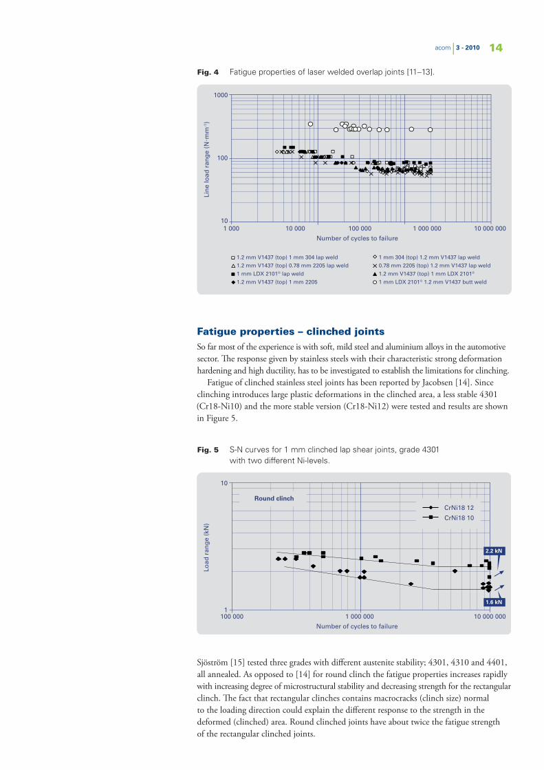
A summary of the results is given in Figure 4. It can also be noted that a wider weld increases the fatigue strength. The fatigue strength in terms of line load range is almost linearly related to the sheet thickness at similar weld width. This means that the nominal net section stress range is equal at about 60 MPa. (This may to be compared with duplex LDX 2101® butt weld with fatigue strength of 278 MPa.) V1437 is a carbon steel.
Fig. 3 S-N curve for 4 mm flanged specimen and 1.5 mm specimen overlap joint in grade 4301.
Lin
e lo
ad r
ang
e (N
. mm
-1)
10
100
1000
1 000 10 000 100 000 1 000 000 10 000 000
Number of cycles to failure
LS (1.5 mm; 0.6 mm bond-line)
LS (1.5 mm; 0.165 mm bond-line)
"Box" LS (4 mm)
14acom | 3 - 2010
Fig. 4 Fatigue properties of laser welded overlap joints [11–13].
Fatigue properties – clinched jointsSo far most of the experience is with soft, mild steel and aluminium alloys in the automotive sector. The response given by stainless steels with their characteristic strong deformation hardening and high ductility, has to be investigated to establish the limitations for clinching.
Fatigue of clinched stainless steel joints has been reported by Jacobsen [14]. Since clinching introduces large plastic deformations in the clinched area, a less stable 4301 (Cr18-Ni10) and the more stable version (Cr18-Ni12) were tested and results are shown in Figure 5.
Sjöström [15] tested three grades with different austenite stability; 4301, 4310 and 4401, all annealed. As opposed to [14] for round clinch the fatigue properties increases rapidly with increasing degree of microstructural stability and decreasing strength for the rectangular clinch. The fact that rectangular clinches contains macrocracks (clinch size) normal to the loading direction could explain the different response to the strength in the deformed (clinched) area. Round clinched joints have about twice the fatigue strength of the rectangular clinched joints.
Lin
e lo
ad r
ang
e (N
. mm
-1)
10
100
1000
1 000 10 000 100 000 1 000 000 10 000 000
Number of cycles to failure
1.2 mm V1437 (top) 1 mm 304 lap weld
1.2 mm V1437 (top) 0.78 mm 2205 lap weld
1 mm LDX 2101® lap weld
1.2 mm V1437 (top) 1 mm 2205
1 mm 304 (top) 1.2 mm V1437 lap weld
0.78 mm 2205 (top) 1.2 mm V1437 lap weld
1.2 mm V1437 (top) 1 mm LDX 2101®
1 mm LDX 2101® 1.2 mm V1437 butt weld
Fig. 5 S-N curves for 1 mm clinched lap shear joints, grade 4301 with two different Ni-levels.
Load
ran
ge
(kN
)
10
1100 000 1 000 000 10 000 000
Number of cycles to failure
Round clinchCrNi18 12
CrNi18 10
2.2 kN
1.6 kN

15acom | 3 - 2010
Summary– Fatigue strength is shown to be independent of material strength for spot welded
joints. – Spot welded, laser welded and clinched joints show similar fatigue properties
for 0.8 – 1.5 mm sheet thickness of about 70 N.mm-1.– Adhesive bonded joints are five times stronger in fatigue loading compared to spot
welded joints.– Weld-bonded joints show a fatigue strength between spot welded and adhesive
bonded joints.
References[1] Nordberg H., Fatigue Properties of Stainless Steel Lap Joints, SAE paper
2005-01-1324. [2] Final Technical Report, Light & Safe-Weight Reduction for Safer, Affordable
Passenger Cars by using extra Formable High Strength Austenitic Steel, European Community under the ‘Competitive and Sustainable Growth’ Programme, 2005.
[3] Goland M. and Reissner E. J., Appl. Mech., 1944, Vol. 2, p. A-17. [4] Linder, J. et al. Swedish Institute for Metals Research, Report IM-3475, 1997. [5] Linder, J. et al. Fatigue Data and Design Methods for Spot Welded Austenitic
and Duplex Stainless Sheet Steels. In Stainless Steels in Transport Industry. Espoo, Finland, 1998.
[6] Wray T., Resistance Spot Welding Of Duplex Stainless Steel, PhD Thesis, Sheffield Hallam University, 2004.
[7] Marples M., PhD programme, Sheffield Hallam University, 2002. [8] Boyes R., Adhesive Bonding of Stainless Steel; Strength and durability.
PhD Thesis, Sheffield Hallam University, 1998.[9] S.McCann S., PhD programme, Sheffield Hallam University, 2003.[10] Ring-Groth M., Adhesive Bonding and Weldbonding of Stainless Steel,
Lic. thesis, Luleå University of Technology, Luleå, 1998.[11] Kaitanov A., Static and Fatigue Strengths of Laser Welded Over-Lap Joints
with Controlled Penetration. Progress Rep., State Univ. of Marine Tech., St.Petersburg, 2002.
[12] Dinsley C., Laser Welding of Austenitic and Duplex Stainless Steel to Zinc-Coated Mild Steel. PhD thesis. Sheffield Hallam University, 2004.
[13] Linder J., et al., Fatigue Strength of Laserwelded Stainless Steel Sheets, Swedish Institute for Metals Research Report IM-2000-529.
[14] Jacobsen J., Beitrag zum umformtechnischen Fügen von Stahlblechteilen mit vorwiegend Austenitischem Gefüge, Tech. Univ. Hamburg-Harburg, Dr.-Ing Dissertation, 1997.
[15] Sjöström P., Mechanical Properties of stainless steel clinched joint, Linköping studies in science and technology, thesis no 1247, Linköping University, 2006.
Reproduced with permission from Jernkontoret. This paper I03-5 was originaly presented at the 6th European Stainless Steel conference – Science and market, Helsinki, Finland. June 10–13, 2008.

www.outokumpu.com
1449EN
-GB
. Art 58. S
ept 2010
Outokumpu Stainless AB, Avesta Research Centre
Box 74, SE-774 22 Avesta, Sweden
Tel. +46 (0) 226 - 810 00, Fax +46 (0) 226 - 810 77
Comments on acom and its articles or suggestions on future articles are appreciated and should be sent to the editor Jesper Gunnarsson at [email protected]
This document is for information only and seeks to provide professionals with the best possible information to enable them to make appropriate choices. Although every effort has been made to ensure the accuracy of the information provided in this document, Outokumpu can not accept any responsibility for any loss, damage or other consequence resulting from the use of this publication. The information provided herein may be subject to alterations without notice.
Activating Your IdeasOutokumpu is a global leader in stainless steel with the vision to be the undisputed number one. Customers ina wide range of industries use our stainless steel and services worldwide. Being fully recyclable, maintenance-free, as well as very strong and durable material, stainless steel is one of the key building blocks for sustainable future.
What makes Outokumpu special is total customer focus – all the way, from R&D to delivery. You have the idea.We offer world-class stainless steel, technical know-how and support. We activate your ideas