outcome 1 - pneumatic systems
TRANSCRIPT

DET Technological Studies Support Materials:Applied Electronics (Int 2) Outcome 1
1
TECHNOLOGICAL STUDIES
Intermediate 2
Mechanical Systems
Section 1
Outcome 1 – Pneumatic Systems

DET Technological Studies Support Materials:Applied Electronics (Int 2) Outcome 1
2

DET Technological Studies Support Materials:Applied Electronics (Int 2) Outcome 1
3
OUTCOME 1
Outcome 1 – Design, construct and evaluate pneumatic systemsWhen the students have completed this unit of work they should be able to:• Interpret pneumatic system and circuit diagrams.• Describe the operation of pneumatic systems• Pipe up/construct pneumatic systems.• Have an appreciation of safety requirements when operating pneumatic systems.• Perform calculations to determine cylinder pressure, piston force and area.• Evaluate pneumatic systems.

DET Technological Studies Support Materials:Applied Electronics (Int 2) Outcome 1
4
INTRODUCTIONPneumatics is all about using compressed air to do work. Compressed air is simplythe air we breathe forced into a small space. Pneumatic systems are more commonthan you would think and are used extensively in industry, for example to moveobjects off a conveyor or hold/clamp parts of an assembly together. In fact,pneumatics is used quite a lot every day.
CAR TYRE
MOVING PARTS IN A PROCESS
BUS DOORS
MS.Int 2.O1 fig 1
You will all have used compressed air when you have blown up a football or the tyreon a bicycle. To understand how pneumatics uses compressed air to do things wesimply need to think of blowing up a balloon. It takes a lot of air to fully inflate theballoon and to stretch the balloon to its full size. If we inflate the balloon too much,the air will force the balloon to burst. If you release the balloon, the air will begin toescape and will propel the balloon around the room until all the air has escaped. Allof this happens because you have squashed or compressed a lot of air inside theballoon and stored up energy.
MS.Int 2.O1 fig 2
Most pneumatic systems rely on a constant supply of compressed air to make themwork. This is provided by a compressor, which is an air pump driven by a motor orengine. The compressor sucks in air and stores it in a tank called a receiver. Thiscompressed air is then supplied to the system through a series of pipes.

DET Technological Studies Support Materials:Applied Electronics (Int 2) Outcome 1
5
Health and SafetyPneumatic devices and systems are safe, clean and reliable but we must learn to usethem properly to avoid accidents. When using pneumatic equipment, we must alwaysfollow these safety rules:
1. Never blow compressed air at anyone, not even yourself.
2. Never let compressed air come into contact with your skin, as this can be verydangerous.
3. Always wear safety goggles when you are connecting and operating circuits.
4. Check that all air lines are connected before turning on the main air supply.
5. Always turn off the main air supply before changing a circuit.
6. Keep your hands away from moving parts.

DET Technological Studies Support Materials:Applied Electronics (Int 2) Outcome 1
6
CYLINDERSPneumatic equipment can be split up into two basic categories of cylinders andvalves.
Cylinders are the ‘muscles’ of pneumatic systems as they are used to move, hold andlift objects. They can even be used to operate other pneumatic components.Cylinders are operated by compressed air and they covert the stored energy into linearmotion.
There are two types of cylinder that we will be using: a single acting cylinder and adouble acting cylinder.
Single Acting CylinderA single acting cylinder requires only one air supply. If we supply compressed air toa single acting cylinder, the air pushes against a piston inside the cylinder and causesit to outstroke. When the piston has fully outstroked it is said to be positive. If westop the supply of air then a spring inside the cylinder causes the piston to instroke toits starting position and the piston is said to be negative. The symbol for a singleacting cylinder is shown below.
MS.Int 2.O1 fig 3
Single acting cylinders are used in situations where their simple design and small sizeare an advantage. They produce small outstroke forces and their use is limited tooperations that only require use of the outstroke. This is because the spring producesonly enough force to instroke the piston.
Double Acting CylinderA double acting cylinder requires two air supplies, one to outstroke the piston and theother to instroke the piston. Compressed air is applied to one side of the piston thenother to make it move positive and then negative. The symbol for a double actingcylinder is shown below.
MS.Int 2.O1 fig 4
Double acting cylinders are used more often in pneumatic systems than single actingcylinders. They are able to produce greater forces and we can take advantage of boththe outstroke and instroke forces to lift and move objects.

DET Technological Studies Support Materials:Applied Electronics (Int 2) Outcome 1
7
VALVESValves provide the necessary control of the compressed air being supplied to thecylinder. They can turn the air on or off, change the direction that the air is flowing oreven slow down the airflow. The most common type of valve is the 3/2 valve.
3/2 ValveA 3/2 valve is so called because it has 3 ports or connections and two states ofoperation. The ports are always numbered in the same way.
Port 1 – main air supply connectionPort 2 – output connection to other componentsPort 3 – exhaust
The valve has two states of operation. One state prevents air from being supplied toother components and the other allows the air to flow freely.
State 1 – Off/Unactuated StateIn this state, the main airflow through the valve is blocked and so air is unable toreach other components such as cylinders. However, any air within the cylinder isable to exhaust through the valve and this will allow the cylinder to return to itsoriginal position. Study the symbol below and ensure that you understand how the airflows through the valve.
1
32
MS.Int 2.O1 fig 5
State 2 – On/Actuated StateIn this state, the main air supply is able to flow freely through the valve and supplycomponents such as cylinders with air. Study the symbol below and ensure that youunderstand how the air flows through the valve.
1 2
3
MS.Int 2.O1 fig 6
The complete symbol for a 3/2 valve combines both states and is usually drawn in theoff or unactuated state. The complete symbol is shown below.
MS.Int 2.O1 fig 7
DET Technological Studies Support Materials:Applied Electronics (Int 2) Outcome 1
8
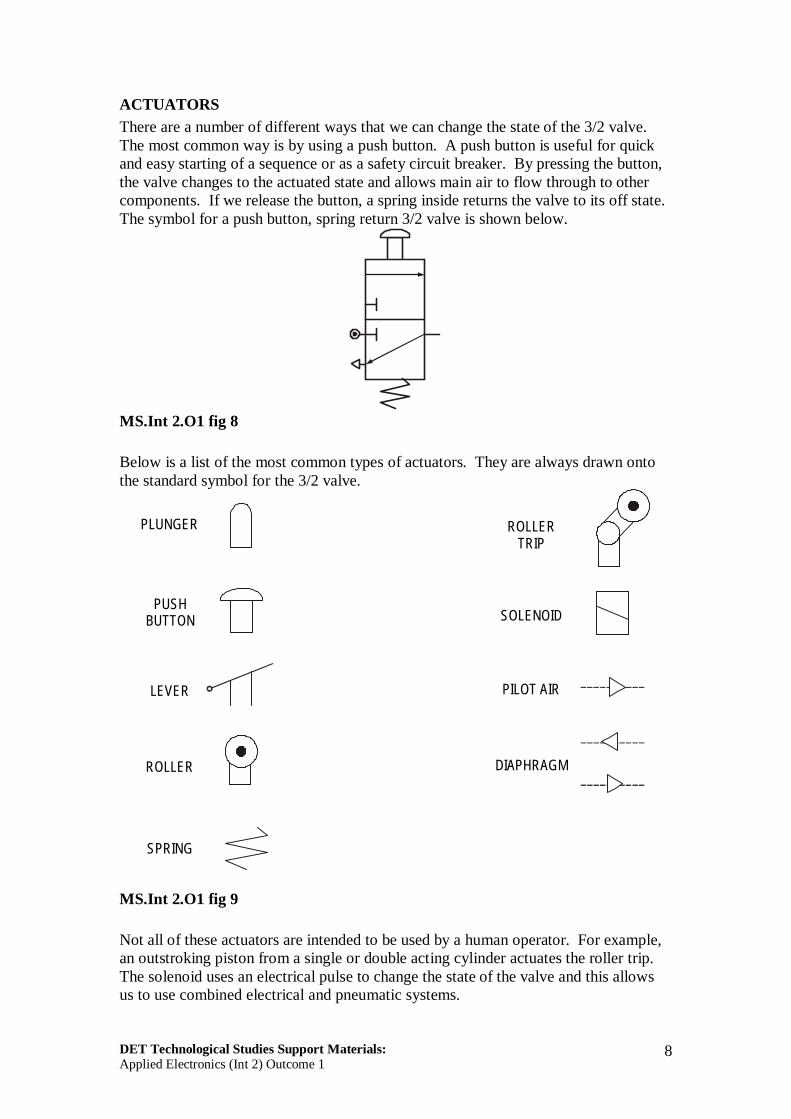
ACTUATORSThere are a number of different ways that we can change the state of the 3/2 valve.The most common way is by using a push button. A push button is useful for quickand easy starting of a sequence or as a safety circuit breaker. By pressing the button,the valve changes to the actuated state and allows main air to flow through to othercomponents. If we release the button, a spring inside returns the valve to its off state.The symbol for a push button, spring return 3/2 valve is shown below.
MS.Int 2.O1 fig 8
Below is a list of the most common types of actuators. They are always drawn ontothe standard symbol for the 3/2 valve.
PLUNGER
PUSHBUTTON
LEVER
ROLLER
ROLLERTRIP
SOLENOID
PILOT AIR
DIAPHRAGM
SPRING
MS.Int 2.O1 fig 9
Not all of these actuators are intended to be used by a human operator. For example,an outstroking piston from a single or double acting cylinder actuates the roller trip.The solenoid uses an electrical pulse to change the state of the valve and this allowsus to use combined electrical and pneumatic systems.

DET Technological Studies Support Materials:Applied Electronics (Int 2) Outcome 1
9
SIMPLE CIRCUITSA bottling plant uses a single acting cylinder to press lids onto bottles. The cylinder iscontrolled by a push button, spring return 3/2 valve. An operator presses the buttonwhen the bottle is in the correct position.
MS.Int 2.O1 fig 10
The pneumatic circuit is shown below.
MS.Int 2.O1 fig 11
When the button is pressed, the valve changes state and supplies air to the singleacting cylinder. This causes the piston to outstroke with enough force to press the lidonto the bottle. When the button is released, the valve returns to its original state andthe piston is able to instroke ready for the process to begin again.

DET Technological Studies Support Materials:Applied Electronics (Int 2) Outcome 1
10
Assignment 11. Build the circuit shown above for the bottling plant.
a. Press the button on the valve and keep it pressed. Explain what happens.b. Release the button and explain what happens.c. Using the correct terminology, explain how the circuit operates to seal the bottles
with the lids.

DET Technological Studies Support Materials:Applied Electronics (Int 2) Outcome 1
11
In a section of a recycling plant, metal cans are dipped in a chemical solution toremove traces of dirt, oil and paint. A double acting cylinder is used to raise andlower a basket containing the cans.
MS.Int 2.O1 fig 12
The pneumatic circuit is shown below.
Valve A Valve B
MS.Int 2.O1 fig 13
When the operator presses the button on valve A, air is supplied to the double actingcylinder which outstrokes and lowers the basket into the chemical solution. When thebutton on valve B is pressed, air is supplied to the other side of the piston whichinstrokes and raises the basket. Any air in the cylinder at this time is able to exhaustthrough port 3 of valve A.

DET Technological Studies Support Materials:Applied Electronics (Int 2) Outcome 1
12
Assignment 21. Build the circuit shown above for raising and lowering the basket.
a. Press the button on valve A to outstroke the cylinder. Does the piston instrokewhen you release the button?
b. Press the button on valve B. What happens to the cylinder?c. What happens when you press both buttons at the same time?d. Leave both valves unactuated and try moving the piston. Why is it so easy to
move?e. Using the correct terminology, explain how the circuit operates to raise and lower
the basket.

DET Technological Studies Support Materials:Applied Electronics (Int 2) Outcome 1
13
5/2 VALVESThe problem with controlling a double acting cylinder with two 3/2 valves is thatwhen neither valve is actuated, no air is being supplied to the cylinder to hold thepiston in place. Any air within the cylinder is able to exhaust through port 3 on eachvalve. This means that any force or effort placed on the piston will make it moveeasily. A further disadvantage is that the 3/2 valve needs to be actuated until thedouble acting cylinder has fully outstroked or instroked. Releasing the valve beforethe stroke is complete will result in the piston stopping short of its final position.
We have greater control over a double acting cylinder if we control its outstroke andinstroke using a 5/2 valve. This valve has 5 ports and two states of operation. Theports are always numbered in the same way.
Port 1 – main air supply connectionPort 2 – output connection to cylinderPort 3 – exhaustPort 4 – output connection to cylinderPort 5 – exhaust
The valve has two states of operation. One state supplies air to outstroke a doubleacting cylinder and the other state will cause it to instroke.
State 1 - InstrokeIn this state, the main air flows through the valve from port 1 to port 2. Any air withinthe cylinder is able to exhaust through the valve from port 4 to port 5. In this state, a5/2 valve will cause a double acting cylinder to instroke or hold the piston in thenegative position as air is always being supplied to the cylinder. Study the symbolbelow and ensure that you understand how the air flows through the valve.
1
2
3
4
5
AIR FROMCYLINDER
AIR TOCYLINDER
MS.Int 2.O1 fig 14

DET Technological Studies Support Materials:Applied Electronics (Int 2) Outcome 1
14
State 2 – OutstrokeIn this state, the main air flows through the valve from port 1 to port 4. Any air on theother side of the piston is able to exhaust through the valve from port 2 to port 3. Inthis state, a 5/2 valve will cause a double acting cylinder to outstroke and hold it in thepositive position. Study the symbol below and ensure that you understand how theair flows through the valve.
1
2
3
4
5
AIR FROMCYLINDER
AIR TOCYLINDER
MS.Int 2.O1 fig 15
The complete symbol for a 5/2 valve is shown. The cylinder, main air and exhaustlines are only ever drawn on one half of the symbol depending on which part is activein the circuit. It is usual, however to draw the symbol in such a way as it would holda double acting cylinder in the negative position.
MS.Int 2.O1 fig 16
5/2 valves can be operated or actuated in the same way as 3/2 valves however, themost common way of actuating a 5/2 valve is pilot air. A pilot air 5/2 valve willchange state when a brief air signal acts at either end of the valve. This signal is mostoften supplied from a 3/2 valve. In the example shown below, the button on Valve Aonly needs to be pressed momentarily in order to change the state of the 5/2 valve.The 5/2 valve will supply the double acting cylinder with air in order for it tooutstroke.

DET Technological Studies Support Materials:Applied Electronics (Int 2) Outcome 1
15
Valve A
MS.Int 2.O1 fig 17
Notice that the pilot air lines to the 5/2 valve are drawn as broken or dashed lines todistinguish them from the other air lines in the circuit.

DET Technological Studies Support Materials:Applied Electronics (Int 2) Outcome 1
16
Assignment 31. A hopper door is connected to the end of a double acting cylinder. Sand is fed
into the hopper from above and when the hopper is full, the door of the hoppermust open to allow the sand to fall through onto a wagon. The hopper door thencloses and the process is able to begin again.
Valve A Valve B
MS.Int 2.O1 fig 18
a. Build and test the circuit shown above for opening and closing the hopper door.b. Does pressing Valve A or Valve B close the hopper door?c. Using the correct terminology, explain how the circuit operates.

DET Technological Studies Support Materials:Applied Electronics (Int 2) Outcome 1
17
2. The door in a secured entry system is controlled by pneumatics. A simplifiedcircuit diagram is shown below with some of the piping missing.
CRANK
SLIDER TRACK
CYLINDER
A
B
C
MS.Int 2 .O1 fig 19
a. Name each of the components A, B and C used in the pneumatic circuit shownabove.
b. Complete the missing piping in the circuit diagram.c. Using appropriate terminology, describe how the systems works from when Valve
A is actuated.

DET Technological Studies Support Materials:Applied Electronics (Int 2) Outcome 1
18
3. A barrier to a company car park is controlled by a security guard. The guardcarefully checks all cars entering the premises. The barrier is to be raised andlowered by a double acting cylinder.
MS.Int 2.O1 fig 20
a. Design a pneumatic system that will solve this problem using equipment that youhave available.
b. Pipe up and test your solution.c. Produce a list of all the components used in your solution using their correct
names.d. Using the correct terminology, describe how your solution raises and lowers the
barrier.e. Why is a double acting cylinder used instead of a single acting cylinder in these
circumstances?

DET Technological Studies Support Materials:Applied Electronics (Int 2) Outcome 1
19
FLOW CONTROL VALVESYou will have noticed in all the circuits you have built so far, that the cylindersoperate very quickly. Sometimes this is exactly what we want but very often it wouldbe dangerous or impractical for the cylinder to work this fast. For example, thinkback to the exercise where a basket was lowered into a chemical solution. If thishappened too fast then the chemical would splash out of the container. In this case,we would want the cylinder to raise and lower the basket slowly.
We can slow down the airflow to a cylinder by using flow control valves. The mostcommon type is the unidirectional restrictor. This type of valve slows down theairflow in one direction only. The symbol is shown below.
MS.Int 2.O1 fig 21
When air flows into the restrictor in the direction shown in figure 22, some of the airtakes the bypass route and forces the ball to seal the path. The air is then forced topass through the restriction and the flow is slowed down. We can alter the flow byadjusting the small screw on the top of the restrictor.
AIRFLOW
RESTRICTION
BYPASSMS.Int 2.O1 fig 22
When air flows in the opposite direction into the restrictor, most of the air takes thebypass route and forces the ball to open up the path. This allows the air to flow freelyand unrestricted.
AIRFLOW
MS.Int 2.O1 fig 23
If we want to restrict the stroke of a cylinder, it is normal practice to restrict theexhaust air coming from the cylinder rather than the main air being supplied to thecylinder. This provides a much smoother motion in the piston.

DET Technological Studies Support Materials:Applied Electronics (Int 2) Outcome 1
20
Remember our example with the hopper door. It would be much more practical forthe door to open slowly, as this would allow the sand to fall more gently into thewagon below. We would still want the door to close quickly so that the process couldbegin again as soon as possible. Study the new circuit diagram below.
Valve A Valve B
MS.Int 2.O1 fig 24
To open the door of the hopper slowly, we need to control the speed of the instroke.When Valve B is pressed, the pilot air 5/2 valve changes state and supplies the air toinstroke the double acting cylinder. However, air is trapped behind the piston and thismust escape or exhaust in order for the piston to move. The restrictor is connected insuch a way that the exhausting air must pass through the restriction. This slows downthe exhaust air and so slows down the speed that the cylinder can instroke.

DET Technological Studies Support Materials:Applied Electronics (Int 2) Outcome 1
21
Assignment 41. Build and test the pneumatic circuit shown above.
a. Using appropriate terminology, explain how the circuit works.b. Explain why the exhaust air has been restricted in order to slow down the instroke.
2. For safety reasons, the entrance door to a storeroom in a warehouse must open andclose slowly. A double acting cylinder is used to slide the door. A simplifiedcircuit diagram is shown below.
MS.Int 2.O1 fig 25
Valve A Valve B
MS.Int 2.O1 fig 26
a. Build and test the pneumatic circuit shown above.b. Explain why two restrictors are needed in this circuit.c. Where would you place the push button, spring return 3/2 valves in relation to the
warehouse door?

DET Technological Studies Support Materials:Applied Electronics (Int 2) Outcome 1
22
Sometimes we might want to control the instroke and outstroke of a single actingcylinder. We can control the instroke in the same way as a double acting cylinder, byrestricting the exhaust air. However, when a single acting cylinder outstrokes thepiston pushes against a spring and there is no exhaust air to control. In this case, weuse two ‘back to back’ restrictors. The spring prevents the jerky action of the pistonthat occurs when this arrangement is used with a double acting cylinder.
A B
MS.Int 2.O1 fig 27
A simpler device for controlling the speed of the outstroke and instroke of a singleacting cylinder is a bi-directional restrictor. This restrictor has just one route for theair and so the same rate of flow is achieved in both directions. A small screw on thetop of the restrictor adjusts the flow rateAlthough this device is more economical than using two unidirectional restrictors, itmeans that the instroke and outstroke speeds will be the same. If used with a doubleacting cylinder then a jerky motion is produced rather than a smooth controlled one.The symbol for a bi-directional restrictor is included in figure 28 below.
MS.Int 2.O1 fig 28

DET Technological Studies Support Materials:Applied Electronics (Int 2) Outcome 1
23
Assignment 51 a. In figure 27, which unidirectional restrictor controls the speed of the outstroke?
b. What is the purpose of the other restrictor in this circuit?
2. Describe some of the disadvantages of using a bi-directional restrictor to controlthe speed of a double acting cylinder.
3. Part of a production line requires the company logo to be stamped on thepackaged goods. The content of the packages is fragile and so care must be takennot to damage the boxes. It has been decided that a single acting cylinder is usedbut it should outstroke slowly to avoid damaging the goods.
BOX BOX BOX BOX
STAM P
MS.Int 2.O1 fig 29
a. Design a pneumatic system that will perform this task.b. Build and test your solution.c. Name each of the components used.d. Using the correct terminology, describe how the circuit operates.
4. As part of a drilling operation, the work piece requires to be held in a vice. Thevice is to be operated pneumatically by a double acting cylinder. To allow theoperator time to position the work piece, the vice must close slowly.
MS.Int 2.O1 fig 30
a. Design a pneumatic system that will perform this task.b. Build and test your solution.c. Name each of the components used.d. Using the correct terminology, describe how the circuit operates.e. The weight of the vice means that a large force is required to open and close it. It
is suggested that two cylinders operating at the same time would be better. Usinga T-piece, alter your circuit so that two double acting cylinders operate at the sametime.

DET Technological Studies Support Materials:Applied Electronics (Int 2) Outcome 1
24
AND CONTROLWe can create basic control circuits using pneumatic equipment relatively easily. Onmany production lines, operators become careless because they are so familiar withthe machine that they constantly use. One way to avoid accidents happening is to fitthe machine with a guard system, where the machine will only operate if the guard isin position and the machine is switched on by the operator.
S LID IN GD O O R
VA LVEP O S IT IO N
S TA RT /S TO PVA LVE
MS.Int 2.O1 fig 31
This type of control can be achieved if we connect two 3/2 valves together in series.
Valve A Valve B
MS.Int 2.O1 fig 32
The single acting cylinder in this circuit will only outstroke if both 3/2 valves areactuated at the same time. This is because Valve B is supplied with air coming fromValve A. Pressing the button on Valve A supplies air to Valve B and if we press thebutton on Valve B at the same time, this allows air to flow into the single actingcylinder and cause it to outstroke.

DET Technological Studies Support Materials:Applied Electronics (Int 2) Outcome 1
25
We can summarise the behaviour of this type of circuit in a truth table.
VALVE A
OFF
ON
OFF
ON
VALVE B
OFF
OFF
ON
ON
CYLINDER
INSTROKE
INSTROKE
INSTROKE
OUTSTROKE
MS.Int 2.O1.fig 33

DET Technological Studies Support Materials:Applied Electronics (Int 2) Outcome 1
26
Assignment 61. A machine in a factory is very difficult to guard without affecting how the
machine carries out its task. The manager is very concerned that the operatormay have an accident as a result. In order to prevent this, the manager wants toredesign the start/stop system of the machine so that the operator needs to presstwo buttons before the single acting cylinder outstrokes.
MS.Int 2.O1 fig 34
a. Design a system that will only work if the operator is pressing two buttons at thesame time.
b. Build and test your system to check that it operates correctly.c. Draw a truth table of your results.d. Using appropriate terminology, describe how the system operates.e. The manager thinks that the single acting cylinder operates too quickly. Alter
your design so that the cylinder outstrokes more slowly.
2. A single acting cylinder is used to bend metal brackets using a former attached tothe end of the piston rod. In order to operate safely, the system must satisfy thefollowing conditions:
• The cylinder must only outstroke if the guard is down.• The process must only start if the operator presses both start buttons.• The process can only begin when the metal is in the correct position and actuates a
3/2 valve.
a. Design a pneumatic circuit to carry out this operation.b. Build and test your solution and ensure that it operates properly.c. Using appropriate terminology, explain how your circuit controls the action of the
single acting cylinder.

DET Technological Studies Support Materials:Applied Electronics (Int 2) Outcome 1
27
OR CONTROLIn many industrial applications, pneumatic systems are controlled by either of twooperators. They may be working together on the same process or controlling aprocess from two different positions. Quality control checks on production linesusually involve two or more people. Damaged or unsatisfactory goods are rejected ifone or other person detects a fault and the goods are removed from the line by a singleacting cylinder.
MS.Int 2.O1 fig 35
This type of control requires two 3/2 valves to be connected together in parallel andthe use of an additional component called a shuttle valve.
Valve A Valve B
Shuttle Valve
MS.Int 2.O1 fig 36

DET Technological Studies Support Materials:Applied Electronics (Int 2) Outcome 1
28
A shuttle valve is a very simple device but it is essential to how an OR control circuitworks. If the button on Valve A is pressed, the ball in the shuttle valve is blownacross towards Valve B and air is directed towards the single acting cylinder. Thiswill outstroke the piston. If the button on Valve B is pressed, the ball is blown acrosstowards Valve A and air is directed towards the cylinder. This also causes the pistonto outstroke.
We can summarise the behaviour of this circuit in a truth table.
VALVE A
OFF
ON
OFF
ON
VALVE B
OFF
OFF
ON
ON
CYLINDER
INSTROKE
OUTSTROKE
OUTSTROKE
OUTSTROKE
MS.Int 2.O1 fig 37

DET Technological Studies Support Materials:Applied Electronics (Int 2) Outcome 1
29
Assignment 71. A window in a large factory is to be opened and closed by a single acting cylinder.
The cylinder is to be controlled by lever operated 3/2 valves, one placed at eitherend of the factory floor as this provides the workers with nearby control. If eitherof the two 3/2 valves is actuated, the cylinder should outstroke and open thewindow.
MS.Int 2.O1 fig 38
a. Design a system that will work if a person at either end of the factory activates alever.
b. Build and test your system to check that it operates correctly.c. Draw a truth table of your results.d. Using appropriate terminology, describe how the system operates.e. Someone suggests changing the shuttle valve to a T-piece. Explain why this is not
a good idea.
2. A pneumatic circuit has been devised for use in operating a sliding door to arefrigerated store in a supermarket. For safety reasons, it must be possible for thedoor to be opened or closed from both inside and outside the room. Additionally,the door should open and close slowly.
MS.Int 2.O1 fig 39

DET Technological Studies Support Materials:Applied Electronics (Int 2) Outcome 1
30
A layout of the components to be used in the system is shown in figure 40.
CLOSE (OUTSIDE)
CLOSE (INSIDE)
OPEN (OUTSIDE)
OPEN (INSIDE)
MS.Int 2.O1 fig 40
a. Complete the circuit so that it operates properly.b. Using appropriate terminology, explain how the circuit operates.c. It is decided after a while that the door should open as quickly as possible but
continue to close slowly. Adjust your circuit to suit these new conditions.

DET Technological Studies Support Materials:Applied Electronics (Int 2) Outcome 1
31
3. A single acting cylinder is used to punch a hole in thin aluminium sheet. Thesheet forms part of a household accessory that the company manufactures. Theprocess can be controlled locally by an operator who must press two buttons at thesame time to outstroke the cylinder. The alternative is to control the process fromthe control area directly above the production line. Both arrangements help toprevent accidents during this potentially dangerous process. The pneumaticcircuit to carry out this process is shown.
Valve A Valve B Valve C
MS.Int 2.O1 fig
a. Build and test the pneumatic circuit shown above.b. Draw a truth table of your results.c. Using appropriate terminology, describe how the system operates.d. When the process is controlled from the control area above the production line, it
is possible that someone working near the cylinder could still be injured, as themachine is not guarded. Redesign the circuit to ensure that the single actingcylinder will only outstroke if a guard is in position.
e. Explain the changes that you have made and how they improve the overallperformance of the circuit.

DET Technological Studies Support Materials:Applied Electronics (Int 2) Outcome 1
32
TIME DELAY CIRCUITSSometimes we require a time delay or pause in a circuit before something elsehappens. Time delays are easily achieved with the use of two additional componentsinserted into the system at the point where the delay is required. The componentsrequired are a unidirectional restrictor (which we have already used) and a reservoir.The arrangement is shown below.
Air
MS.Int 2.O1 fig 41
A reservoir is simply an empty container. When placed in a circuit it takes some timeto fill up with air and restore the working pressure of the circuit. The time it takes tofill creates the pause or delay. We can change the length of the delay in two ways.The first is to use a reservoir of a different size as large reservoirs take longer to fill.The second way is to adjust the flow of air into the reservoir using a unidirectionalrestrictor. We can slow down the airflow using the restrictor so that the air takes amuch longer time to fill the reservoir.
Time delay circuits can be useful in clamping or pressing applications where pressureis applied by a cylinder for a set time. Such a circuit can be used to make plasticcontainers. This type of pressing system makes use of a double acting cylinder topress a hot plastic sheet into a mould. The plastic needs to be held in position forseveral seconds to allow it to cool. The circuit for this system is shown in figure 42.

DET Technological Studies Support Materials:Applied Electronics (Int 2) Outcome 1
33
3
3
3
1
1
1
1
1
1
2
2
2
2
2
4
4
5
H O T P LA S T ICS H E E T
MS.Int 2.O1 fig 42
When the push button, spring return 3/2 valve is pressed, the 5/2 valve changes stateand the cylinder containing the former outstrokes. When fully outstroked, the formerforces the plastic sheet into the mould and at the same time trips the roller. Althoughthis 3/2 valve has been actuated, the instroke is delayed because of the time delay.The airflow to the reservoir is slowed and it takes several seconds for the reservoir tofill. This allows the plastic container to cool before it is released when the pistonfinally instrokes.

DET Technological Studies Support Materials:Applied Electronics (Int 2) Outcome 1
34
Assignment 81. Build and test the pneumatic circuit shown in figure 42.
a. Adjust the circuit to achieve a 2 second delay. Explain how to do this.b. Explain the difference between piston speed control and a time delay.c. Describe how the time delay could be increased to 10 seconds.
2. A machine is designed to test for wear and tear on drawer guides in a kitchen unit.A double acting cylinder is used to constantly open and close the drawer and therunners are checked regularly.
DRAWER GUIDES
KITCHEN UNIT
DRAWER
PISTON MOVEMENT
A
B
C
X
MS.Int 2.O1 fig 43
a. Build and test the pneumatic circuit shown in figure 43.b. Name the components labelled A, B and C.c. Describe how the circuit operates to complete one cycle of operation from the
position shown.d. To allow the system to be stopped and checked, a 3/2 lever operated spring return
valve is inserted at point X in the circuit. Adjust the circuit to contain this valve.Explain why this is an improvement to the original design.

DET Technological Studies Support Materials:Applied Electronics (Int 2) Outcome 1
35
3. A double acting cylinder is used to mark out even sections of fudge on a foodproduction line. It is important that the process runs continuously and that eachfudge bar is the same size. Pneumatics is used in many food production linesbecause it is clean, safe and reliable to use. The circuit diagram is shown below.
MS.Int 2.O1 fig
a. Build and test the circuit shown above.b. Adjust the restrictors so that the delay on each side is the same or as close as you
can make it.c. This circuit is designed to run constantly but sometimes the machinery needs to be
cleaned. The only way to shut the process down is to shut down the main airsupply. Insert a 3/2 valve in the circuit that will allow the process to be stopped atany time. Explain your choice of actuator for this valve.
d. Are there any other problems with this system that you think may affect the size ofthe fudge bars?
e. Why is pneumatics a good choice for this type of production line?

DET Technological Studies Support Materials:Applied Electronics (Int 2) Outcome 1
36
AIR BLEED CIRCUITSWhen designing pneumatic circuits it is often necessary to detect if something is inplace before the operation of the circuit continues, for example that a work piece to bedrilled is in the correct position. It is possible to use some actuators on 3/2 and 5/2valves (such as a plunger or roller trip), to detect this but sometimes they interferewith the set up of the system or are not sensitive enough. To overcome theseproblems, we use what is known as an air bleed circuit.
The diagram below shows the junction between two conveyor systems in a factory.Boxes are transferred from one conveyor to another by the action of a single actingcylinder. The boxes are fairly light and an air bleed is used to detect when a box is inthe correct position ready for transfer.
A IR B L E E D
S IN G LE A C TIN GC Y LIND E R
C O N V E Y O R B E LTS
MS.Int 2.O1 fig 44
The circuit used to achieve this is shown below.
MS.Int 2.O1 fig 45
Main air in the circuit is connected to a unidirectional restrictor in such a way as toslow down the airflow. Air passes through the restrictor to a T piece, one end ofwhich has an unconnected pipe that allows the air to escape or bleed out into theroom. When the boxes block the air bleed, the pressure in the pipe increases and thisair provides a pilot air signal to the diaphragm valve. This actuates the 3/2 valvewhich in turn outstrokes the cylinder and the box is moved from one belt to the other.The single acting cylinder instrokes automatically ready for the process to beginagain.

DET Technological Studies Support Materials:Applied Electronics (Int 2) Outcome 1
37
Assignment 91. Build and test the pneumatic circuit shown in figure 45.
a. Explain what happens when the air bleed is blocked.b. Why is an air bleed more useful for sensing when an object is in place than a
plunger operated 3/2 valve?
2. A paper mill uses a large guillotine controlled by a double acting cylinder to cutthe reams of paper to size. An air bleed is used to detect when the paper is inposition ready to be cut.
MS.Int 2.O1 fig 46
The pneumatic circuit to solve this problem is shown below.
MS.Int 2.O1 fig 47
a. Build and test the circuit shown above.b. What is the purpose of the roller trip, spring return 3/2 valve? What would you
expect to activate this valve?c. It is discovered that the roller trip isn’t always actuated and needs to be reset
manually by an operator. It is very dangerous for the workers to be so close to theguillotine blade and so it is decided to change the roller trip to an air bleed.Redesign the circuit to take account of this.

DET Technological Studies Support Materials:Applied Electronics (Int 2) Outcome 1
38
3. A double acting cylinder is used to form hot acrylic sheet into the shape of soapdishes. The process is started by an operator pressing a button which causes thedouble acting cylinder to outstroke. It is important that the plastic is pushed fullyinto the mould before the cylinder instrokes. To ensure this, two air bleeds areused to ‘sense’ that the soap dish has been fully formed.
MS.Int 2.O1 fig 47a
a. Design a pneumatic circuit that will carry out this operation.b. Build and test your solution to ensure that it operates correctly.c. Using the correct terminology, describe how your circuit operates.d. Explain why air bleeds are a good choice for detecting that the dish has been
formed correctly. Can you suggest another way of achieving this?e. A further improvement to the system is that it should only operate when the
acrylic sheet is in the correct position, otherwise some of the dishes are not formedproperly. Redesign the circuit taking this into account.

DET Technological Studies Support Materials:Applied Electronics (Int 2) Outcome 1
39
4. An automatic door is designed so that, when the door is opened there is a timedelay before it automatically closes again. An air bleed is used to detect when aperson is approaching the door as the piping can be easily hidden under theentrance mat. The pneumatic circuit is shown below.
MS.Int 2.O1 fig 47b
a. Build and test this circuit and ensure that it operates properly.b. Study the circuit diagram carefully and explain what is controlling the instroke of
the cylinder.c. Using appropriate terminology, explain how the circuit operates.d. Alter the circuit so that the door closes slowly.e. Describe any problems that may be encountered if this system was to be used at
the entrance of, say, a hospital.

DET Technological Studies Support Materials:Applied Electronics (Int 2) Outcome 1
40
SEMI-AUTOMATIC CIRCUITSIn a semi-automatic circuit, either the instroke or outstroke of the piston is automatic.The most commonly used semi-automatic circuits involve an operator starting thecircuit and when the piston is fully outstroked, it actuates a valve that controls theinstroke. We have come across examples of semi-automatic circuits in the coursealready.
On some production lines, drilling operations are started by an operator who is able toensure that the component to be machined is in the correct position. When the holehas been drilled to the correct depth, a roller trip is activated which automaticallyinstrokes the cylinder.
D E P T H S TO P
R O LLE R T RIP
D RILL
W O R K P IE CE
MS.Int 2.O1 fig 48
The pneumatic circuit that controls this operation is shown below.
Valve A
MS.Int 2.O1 fig 49

DET Technological Studies Support Materials:Applied Electronics (Int 2) Outcome 1
41
The operator starts the operation by pressing the push button. This changes the stateof the 5/2 valve and the cylinder outstrokes. The cylinder pushes the drill into thework piece and when the correct depth has been reached, the roller trip is activated.This changes the state of the 5/2 valve and the cylinder instrokes. The process isready to begin again.

DET Technological Studies Support Materials:Applied Electronics (Int 2) Outcome 1
42
Assignment 101. Build and test the pneumatic circuit shown in figure 49.
a. Why is this type of circuit described as semi-automatic?b. The drill is inserted into the work piece too quickly for the hole to be drilled
properly. Alter the circuit so that the outstroke is slower.
2. A guard on a plastic forming machine is held in position by a double actingcylinder. The guard is raised to allow the worker to remove the component andinsert a blank. The guard is raised on the push of a button but lowersautomatically.
TRAV
EL O
F D
OO
R
G U IDE S
MS.Int 2.O1 fig 50
a. Design a semi-automatic circuit that will automatically lower the guard byoutstroking the piston.
b. The operator complains that the guard raises and returns too quickly and hedoesn’t have enough time to remove the component. Someone suggests slowingdown the outstroke while another designer thinks that a time delay circuit wouldbe better. How would you improve the circuit? Explain your decision.
c. Rebuild the improved circuit and test it.d. Using appropriate terminology, explain how the circuit operates.

DET Technological Studies Support Materials:Applied Electronics (Int 2) Outcome 1
43
3. Quality control on a production line is very important to ensure that all productsare made to the correct standard. A quality control officer can randomly selectgoods on the line to be checked. He does this be pressing a button which activatesa double acting cylinder which pushes the object off the line. However,sometimes the goods can become jammed and the piston should automaticallyinstroke. A circuit is shown below.
VALVE A
VALVE B
MS.Int 2.O1 fig 50a
a. Build and test the circuit shown above.b. Explain the purpose of Valves A and B.c. Why is this described as a semi-automatic circuit?

DET Technological Studies Support Materials:Applied Electronics (Int 2) Outcome 1
44
AUTOMATIC CIRCUITSAutomatic circuits can perform tasks over and over again without the need of inputfrom an operator. These circuits make use of actuators such as a roller trip andplunger to sense the position of the piston. We have come across an automatic circuitalready in the course.
Automatic control circuits are used in applications that require reciprocating motionof the piston. For example, a production line requires the finished products to bedirected towards two loading bays ready for shipping out to customers. A doubleacting cylinder controls the movement of a chute so that every second container issent to each bay.
MS.Int 2.O1 fig 51
The pneumatic circuit that controls this operation is shown below. Notice that rollertrip, spring return 3/2 valves are used to detect when the piston is positive andnegative.
Valve A Valve B
XY
MS.Int 2.O1 fig 52
As the piston instrokes, it trips Valve A and the 5/2 valve changes state and the pistonis sent positive. When it is fully outstroked, it trips Valve B and the 5/2 valve returnsto its original position allowing the piston to instroke. The process begins all overagain and continues to operate.

DET Technological Studies Support Materials:Applied Electronics (Int 2) Outcome 1
45
Assignment 111. Build and test the pneumatic circuit shown in figure 52.
a. Sometimes the containers get trapped or jammed in the system and it needs to beswitched off. How do you get the circuit to stop? Is this an acceptable way ofcontrolling the circuit?
b. Someone suggests placing a lever operated 3/2 valve in the circuit at position Xbut another worker disagrees and believes it should be point Y. Try both positionsand explain how these changes affect the operation of the circuit.
c. Why must a lever operated 3/2 valve be used instead of a push button?
2. A polishing machine requires reciprocating motion of a double acting cylinder.So that the polished work piece can be removed, a valve is required to stop theoperation of the complete circuit. Experience of this type of process shows that ifthe piston operates too quickly, the brush becomes hot and sticks to the surface ofthe material.
MS.Int 2.O1 fig 53
a. Design a pneumatic circuit that will carry out this operation.b. Build and test your solution and ensure that it fully solves the problem.c. Using appropriate terminology, explain how you circuit works.d. Why do we describe this type of circuit as automatic?

DET Technological Studies Support Materials:Applied Electronics (Int 2) Outcome 1
46
SEQUENTIAL CIRCUITSMany pneumatic systems and machines are designed to perform a range of tasks in acertain order or sequence. This usually involves the use of two or more cylindersworking together to complete the task.
For example, a company has automated its production line that involves metal blocksbeing placed in a furnace for heat treatment. One cylinder is used to open the furnacedoor and another pushes the metal blocks into the furnace.
A
MS.Int 2.O1 fig 54
The sequence of operations for this process is:
a. An operator pushes a button to start the process.b. The furnace door is opened.c. The block is pushed into the furnace and the piston retracts.d. The furnace door is closed.e. The sequence stops.
For this system to work successfully, we need to fully understand the order andmovement of cylinders A and B.
Stage 1Cylinder A instrokes to raise the furnace door.
Stage 2Cylinder B outstrokes and pushes the metal block into the furnace.
Stage 3Cylinder B instrokes.
Stage 4Cylinder A outstrokes and closes the furnace door.

DET Technological Studies Support Materials:Applied Electronics (Int 2) Outcome 1
47
The pneumatic circuit that carries out this operation is shown below.
CYLINDER B
CYLINDER A
VALVE A
VALVE B
VALVE C
VALVE D
VALVE E
VALVE F
VALVE G
VALVE H
VALVE I
MS.Int 2.O1 fig 55

DET Technological Studies Support Materials:Applied Electronics (Int 2) Outcome 1
48
The system begins by actuating Valve A. This changes the state of Valve B andcauses Cylinder A to instroke, raising the door. When fully instroked or negative, thepiston trips Valve C and this sends a signal to Valve D. This 5/2 valve changes stateand sends Cylinder B positive. When fully outstroked, the piston trips Valve E andthe cylinder instrokes. When negative, Valve F is actuated and causes Cylinder A tooutstroke and stay in the positive position. The system stops and waits for a signalfrom Valve A.
We can summarise the sequence of this circuit as follows:Start, A-, B+, B-, A+, Stop

DET Technological Studies Support Materials:Applied Electronics (Int 2) Outcome 1
49
Assignment 121. Build and test the pneumatic circuit in figure 55.
a. Name the components labelled Valve D, Valve F and Valve H.b. If Valve H was removed from the circuit, explain the effect this would have on the
operation of the furnace door.c. Using appropriate terminology, explain how the circuit operates from when Valve
A is pressed.d. A short delay is required before Cylinder B goes positive. Alter your circuit to
take this into account.
2. A company has automated a small section of its production line. The systeminvolves a component being pushed into position by a cylinder, drilled and thenreleased ready to begin again. The system involves two cylinders workingtogether in sequence: A+, B+, A-, B-. The system is automatic and shouldcontinue to work through the sequence. However, a start/stop button should beincorporated that would allow the system to be shut down in the event of a jam orthe drill bit breaking.
C Y LIND E R B
C Y LIND E R AD RILL
G U IDE SMS.Int 2.O1 fig 56
a. Design a pneumatic system that would carry out this sequence of operations.b. Build and test your solution.c. Using appropriate terminology, describe how it completes one sequence.d. Explain your choice of actuators that sense the fully instroked and outstroked
positions of the two pistons.

DET Technological Studies Support Materials:Applied Electronics (Int 2) Outcome 1
50
3. Engraving is an operation that requires great skill and is very time consuming. Inan attempt to speed up the process, two double acting cylinders are needed towork together in sequence to position the component and hold it in place. CylinderA pushes the component to be engraved into position. The clamping process isachieved by connecting a parallel linkage system to the end of cylinder B. Whenthe cylinder instrokes, the linkage closes around the component to hold it steady.The complete sequence required is A+, B-, A-, B+.
a. Design a pneumatic circuit to carry out this sequence.b. Build and test the circuit and ensure that it operates correctly.c. It is felt that the clamping operation works too quickly and sometimes the
component is moved out of line. Alter your circuit so that cylinder B instrokesmore slowly.
d. Not enough time is allowed for the engraving operation to take place before thecomponent is released. A short delay is needed in the circuit. Using the correctcomponents, position the delay where you think it would be most effective.Explain your reasons for inserting it there.

DET Technological Studies Support Materials:Applied Electronics (Int 2) Outcome 1
51
INTERFACING AND ELECTRONIC CONTROL
Electronic ControlAlthough pneumatic circuits have many advantages, they can become complicatedand expensive when lots of components are needed. They can also be difficult to setup and control. One possible way of overcoming these problems is to use electronicsor a computer interface to control the operation of pneumatic circuits. The advantageof this is that electronic signals can be transmitted over much greater distances thanpneumatic signals. However, the main advantage is that electronic signals respondfaster than pneumatic signals and use less energy.
To control a pneumatic system electronically, we require the use of a solenoidoperated 3/2 valve. This valve is actuated when an electric current energises the coilof the solenoid. If we can control the current flowing to the coil, then we can controlthe operation of the entire circuit. This can be achieved easily by connecting switchesor sensors in series with the solenoid.
For example, a ten-pin bowling complex uses double acting cylinders to set up theskittles once they have been knocked down. The cylinder is controlled by an electricswitch arrangement which energises solenoid operated 3/2 valves.
MS.Int 2.O1 fig 57
The circuit diagram is shown below.
12V dc 12V dc
A
BC
MS.Int 2.O1 fig 58

DET Technological Studies Support Materials:Applied Electronics (Int 2) Outcome 1
52
Assignment 131. Build and test the electrical and pneumatic circuit shown in figure 58.
a. What advantages are there of controlling pneumatic circuits electronically?b. If only pneumatic components were available, redesign the circuit so that it would
carry out the same operation.
2. A waste disposal system makes use of a hopper and container. The containermoves forward under the hopper, which tips up to empty its contents. Limitswitches are used to detect if the container is in place and if the hopper has beentipped up properly. The system needs a start/stop button that will allow overallcontrol of the circuit.
a. Design an electronic and pneumatic system to fully solve this problem.b. Using appropriate terminology, explain how the circuit operates.c. Give examples of other ‘sensors’ that could be used to detect if the container and
hopper are in the correct place.d. It is discovered that once the hopper has tipped right over, the double acting
cylinder begins to instroke before all the contents have emptied out. Insert a timedelay into the circuit that will overcome this.

DET Technological Studies Support Materials:Applied Electronics (Int 2) Outcome 1
53
Reprogrammable InterfacingMost industrial pneumatic systems include a number of cylinders working together insequence. Certain sequences of operation are difficult to control using the equipmentwe have come across so far. The circuits also become expensive to build and aredifficult to set up. However, we can overcome these problems by using a computerinterface to control complex tasks.
For example, a post office sorting system is used to separate three different sizes ofpackages. The packages are carried on a conveyor belt to the first sort. At this point,a single acting cylinder removes the largest packages, which are detected by use of aswitch. At the second stage, the medium packages are separated from the smaller sizeones, which continue to the end of the conveyor. As the content of the packages isunknown, they should be removed carefully from the conveyor. For safety reasons,the system should not operate unless the guard around the conveyor is in position.
MS.Int 2.O1 fig 60

DET Technological Studies Support Materials:Applied Electronics (Int 2) Outcome 1
54
The operation of this circuit can be summarised in a flow chart.
START
ISGUARDDOWN?
NO
YES
ISPACKAGELARGE?
YES
EJECTPACKAGENO
ISPACKAGEMEDIUM?
YES
EJECTPACKAGENO
MS.Int 2.O1 fig 61

DET Technological Studies Support Materials:Applied Electronics (Int 2) Outcome 1
55
Assignment 141a. Write a program that will control the operation of this circuit.b. Build the necessary pneumatic and electronic system and connect it to your
interface. Test that your circuit operates properly.c. It is suggested that there should be a start/stop button to halt the system in case of
a jam. Make the necessary adjustments to your program and circuit toaccommodate this.

DET Technological Studies Support Materials:Applied Electronics (Int 2) Outcome 1
56
2. A system is designed to control a chemical process. A cylinder moves a containerover the tank containing the chemical solution. Another cylinder lowers thecontainer into the tank. The chemical reaction takes several seconds to complete.The cylinder lifts the container and it returns to its original position to beunloaded.
CYLINDER A
CYLINDER B
TANK
MS.Int 2.O1 fig 62
a. Write a program that will control this operation.b. Build the necessary pneumatic and electronic system and connect it to your
interface. Test that the circuit operates properly.c. Investigate the reasons why this circuit would be very difficult to control using
pneumatic equipment only.

DET Technological Studies Support Materials:Applied Electronics (Int 2) Outcome 1
57
3. Packets of sweets in a factory are boxed automatically. The packets pass along aconveyor belt and drop into the boxes. Each box should contain 12 packets only.When full, the box is pushed onto another conveyor by a double acting cylinderand taken away to be labelled and dispatched. A single acting cylinder pushes anempty box into position ready for the process to begin again.
a. Draw a flow chart that clearly shows this operation.b. From your flow chart write a computer program that will control the counting
sequence and the operation of the cylinders.c. Build and test your solution and ensure that it works properly.d. Describe what would happen if no empty box was in place to collect the sweets.
How could you overcome this problem?e. Describe any necessary safety precautions that would need to be in place for this
system to work safely. Have you included these in your design?

DET Technological Studies Support Materials:Applied Electronics (Int 2) Outcome 1
58
FORCES IN A SINGLE ACTING CYLINDERWhen a single acting cylinder outstrokes it produces a force. We can use this force tolift objects or push them around. The size of the force produced by the cylinder as itoutstrokes depends on two things - the air pressure supplied to the cylinder and thesurface area of the piston. This means that we can increase the force by eitherincreasing the air pressure or increasing the size of the piston. However, systems andcomponents are designed to operate at specific pressure levels and we should neverincrease the pressure beyond these levels.
The force produced by the cylinder as it instrokes is not affected by either of thesethings. The instroking force is controlled by the return spring.
PressureAir pressure is measured in bar or in N/mm2. We can measure the pressure in apneumatic system using a pressure gauge. A gauge will always be connected to thecompressor but other gauges may be distributed throughout large systems to monitorthe pressure. This helps to detect leaks, as the pressure in the system would begin tofall if air was escaping from the pipes.
Whenever we use pressure in calculations we require the units to be in N/mm2. Thisoften means converting from bar to N/mm2. This conversion is easy as you simplydivide the value in bar by 10. For example, if the pressure supplied to a system is 5bar, we can find the equivalent value in N/mm2 by simply dividing 5 by 10.Therefore, the value would be 0.5 N/mm2.
The chart below provides a quick reference.
0
0
1 2 3 4 5 6 7 8 9 10
0.1 0.2 0.3 0.4 0.5 0.6 0.7 0.8 0.9 1
bar
N /m m 2
MS.Int 2.O1 fig 63
AreaThe surface area of the piston is the area that the air pushes against to outstroke thepiston. This area is circular or round.
MS.Int 2.O1 fig 64

DET Technological Studies Support Materials:Applied Electronics (Int 2) Outcome 1
59
The surface area is calculated using the formula:
4
22 d
rArea ππ ==
ForceThe force produced as a single acting cylinder outstrokes is calculated using theformula:
AreaessureForce ×= Pr
where force is measured in Newtons (N); pressure is measured in N/mm2 and area ismeasured in mm2.
Worked example:Air is supplied to a single acting cylinder at a pressure of 4 N/mm2. The diameter ofthe piston is 25 mm. Calculate the force produced as the piston outstrokes.
Pressure = 4 N/mm2
222
4914
2514.3
4mm
dArea =×== π
NAreaessureForce 19644914Pr =×=×=
Force = 1.96 kN

DET Technological Studies Support Materials:Applied Electronics (Int 2) Outcome 1
60
Assignment 151. What force is produced by a piston with a diameter of 20 mm supplied with air at
a pressure of 0.3 N/mm2?
2. What force will be produced by a 20 mm diameter cylinder as it goes positiveusing a pressure of 0.8 N/mm2?
3. Calculate the outstroke force produced by a 40 mm diameter cylinder when itoperates with a supply pressure of 3 bar.
4. A stamping machine exerts a force of 454 N with a piston diameter of 34 mm.Calculate the air pressure required for this operation.
5. A machine that places tops on bottles uses a single acting cylinder. The processrequires a force of 650 N. What air pressure needs to be supplied to the cylinderwith a diameter of 56 mm?
6. A force of 540 N is needed to push a packing case off a conveyor belt. The singleacting cylinder used has a diameter of 60 mm. What air pressure should besupplied to the system?
7. A force of 500 N is needed to open a sliding door. The single acting cylinderavailable has a piston diameter of 50 mm. What air pressure should be supplied?
8. A single acting cylinder is used to lift parcels onto a conveyor. This requies aforce of 180 N with the system operating at a pressure of 6 bar. Calculate the areaof the piston required.
9. A door requires a force of 400 N to slide it open. A single acting cylindersupplied with a pressure of 5 bar controls the operation. Calculate the diameter ofthe piston required to produce this force.
10. A furnace door weighs 100 N and is lifted by a single acting cylinder as itoutstrokes. Compressed air is supplied at a pressure of 4 bar. Calculate thediameter of piston required to raise the door.

DET Technological Studies Support Materials:Applied Electronics (Int 2) Outcome 1
61
FORCES IN A DOUBLE ACTING CYLINDERWe already know that a double acting cylinder can be much more useful to us inpneumatics because both the outstroke and instroke are controlled by compressed air.This allows us to make use of the outstroke force and the instroke force. What welearn however, is that the outstroke force is greater than the instroke force. Why isthis the case?
During the outstroke, the compressed air pushes against the surface area of the pistonin the same way as the single acting cylinder.
MS.Int 2.O1 fig 65
However, during the instroke the surface area is reduced because of the piston rod.This means that the compressed air does not have as big an area to push against and soit does not produce as big a force.
MS.Int 2.O1 fig 66
We can find this surface area or effective area as it is known, by calculating the areaof the piston rod and subtracting it from the surface area of the piston.

DET Technological Studies Support Materials:Applied Electronics (Int 2) Outcome 1
62
Worked example:A double acting cylinder has a piston with a diameter of 25 mm. The piston rod is 5mm in diameter. Pressure is supplied to the system at 4 N/mm2. Calculate the forceproduced by the cylinder as it outstrokes and instrokes.
a. Outstroke force
Pressure = 4 N/mm2
222
4914
2514.3
4mm
dArea =×== π
NAreaessureForce 19644914Pr =×=×=
Outstroke force = 1.96 kN
b. Instroke force
Pressure = 4 N/mm2
Effective area = Piston area – Piston rod area
222
4914
2514.3
4mm
dPistonarea =×== π
222
204
514.3
4mm
dreaPistonroda =×== π
Effective area = Piston area – Piston rod area = 491 – 20 = 471 mm2
NreaEffectiveaessureForce 18844714Pr =×=×=
Outstroke force = 1.88 kN

DET Technological Studies Support Materials:Applied Electronics (Int 2) Outcome 1
63
Assignment 161. Explain why the forces produced by a double acting cylinder on the outstroke and
instroke are different.
2. A double acting cylinder has a piston diameter of 20 mm and is supplied with airat a pressure of 0.3 N/mm2. What force is produced as the piston outstrokes?
1. The piston rod has a diameter of 6 mm. What force is produced on the instroke?
2. A double acting cylinder is used to raise and lower a barrier in a car park. The airpressure is 0.4 N/mm2 and the piston has a diameter of 40 mm. The piston rod is12 mm in diameter. What forces are produced when the piston outstrokes andinstrokes?
3. A double acting cylinder produces a force of 0.4 kN. The effective area of thepiston is 0.04 m2. What pressure should be supplied to the cylinder?

DET Technological Studies Support Materials:Applied Electronics (Int 2) Outcome 1
64
Assignment 171. Give three examples of the everyday use of compressed air.
2. What device is used to supply pneumatic systems with compressed air?
3. Give two reasons why pneumatic systems are used in industry.
4. List the safety rules that we must observe when using pneumatic equipment.
5. Draw the symbol for the following pneumatic components:a. single acting cylinderb. double acting cylinderc. unidirectional restrictord. bidirectional restrictore. shuttle valvef. reservoirg. push button, spring return 3/2 valveh. pilot air operated 5/2 valve
6. Name the actuators shown below.
MS.Int 2.O1 fig 67
7. Why are double acting cylinders used more often than single acting cylinders inindustrial applications?
8. Explain the reasons why a 5/2 valve is better for controlling a double actingcylinder than a 3/2 valve.
9. Explain, with the use of diagrams, how a unidirectional restrictor controls airflowin one direction but not the other.

DET Technological Studies Support Materials:Applied Electronics (Int 2) Outcome 1
65
10. How do we control the speed of the outstroke of a double acting cylinder? Whyis it done this way?
11. Describe some of the functions that valves carry out in circuits.
12. Explain how a pneumatic AND circuit works and give one practical example ofits use.
13. Explain how a shuttle valve works.
14. Which two components are used together to create a time delay? Explain howthe components achieve the delay.
15. What is an air bleed and explain how it is used in pneumatic circuits.
16. Packages in a sorting system push against a plunger operated, spring return 3/2valve. This triggers a single acting cylinder that ejects the package from the line.However, some packages are too light and don’t always operate the plunger.Describe, with the use of diagrams, an alternative method of controlling thesingle acting cylinder.
17. Describe the difference between semi-automatic and automatic circuits.
18. What type of motion does an automatic circuit produce?
19. What is a sequential circuit?
20. What advantages are there in controlling pneumatic circuits with electronics?
21. In the formula Force = Pressure x Area, area is measured in mm2. What units dowe use to measure pressure and force?
22. What are gauges used for in pneumatic circuits?
23. Explain why the force produced by the instroke of a double acting cylinder is lessthan the outstroke.
24. Explain how we might increase the size of force produced by a double actingcylinder.
25. Find out the typical working pressures of a car tyre and bicycle tyre. Give thevalues in both bar and N/mm2.