ospre critical design review
TRANSCRIPT

OSPRE
Critical Design Review
1

Project Purpose and Objectives
2 Objectives CPEs Design Requirements Satisfaction
Validation Risk Planning

Mission Description
• To use optical relative navigation
to determine a spacecraft’s state
vector and state vector error
during a lunar transit
• CubeSat based on NASA
CubeQuest challenge – Lunar Mission
– Launch on SLS EM-1
• Customer: Lockheed Martin
3
Lunar cubesat
Objectives CPEs Design Requirements Satisfaction
Validation Risk Planning

Relative Navigation
4 Objectives CPEs Design Requirements Satisfaction
Validation Risk Planning

Mission CONOPS
5 Objectives CPEs Design Requirements Satisfaction
Validation Risk Planning

Functional Requirements
6
FR 0.0 - Provide relative navigation from an image sensor package
on a lunar trajectory.
FR 1.0 - Provide state vector within desired error bounds:
• Velocity: ± 250 m/s Position: ±1000 km
FR 2.0 - Meet dimensional requirements:
• 50 x 50 x 10 mm
FR 2.1 - Meet electrical requirements:
• 3.3, 5, or 12VDC, 0.5A (max), 3W (max)
FR 2.2 - Meet interfacing requirements:
• SPI or I2C
Objectives CPEs Design Requirements Satisfaction
Validation Risk Planning

Critical Project Elements
7 Objectives CPEs Design Requirements Satisfaction
Validation Risk Planning

Critical Project Elements
Solution Accuracy • State vector must be determined to within the
required accuracy
8
Camera resolution Finite camera resolution limits the
information we can obtain from
an image
Image Processing Imperfect image processing
introduces error
Navigation algorithms Imperfect navigation algorithms
introduce error
Objectives CPEs Design Requirements Satisfaction
Validation Risk Planning
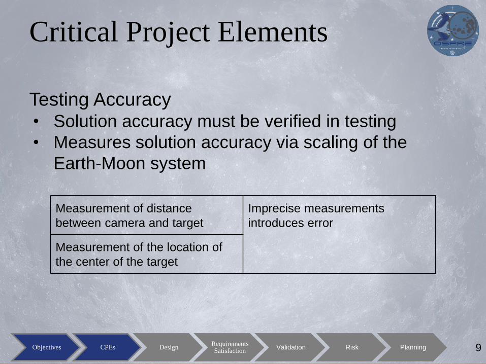
Critical Project Elements
Testing Accuracy • Solution accuracy must be verified in testing
• Measures solution accuracy via scaling of the
Earth-Moon system
9
Measurement of distance
between camera and target
Imprecise measurements
introduces error
Measurement of the location of
the center of the target
Objectives CPEs Design Requirements Satisfaction
Validation Risk Planning

Critical Project Elements
SWAP • Size, Weight, And Power requirements must be met
10
Component size Components that are too large
violate volume constraints - this
driver has limited camera options
Component power draw Components that draw too much
power violate power constraints
Component weight Components that are too heavy
violate weight constraints
Objectives CPEs Design Requirements Satisfaction
Validation Risk Planning

Design Solution
11 Objectives CPEs Design Requirements Satisfaction
Validation Risk Planning

12 12

13 13

14 14

15 15

16 16

17 17

18 18
19 19

Functional Flow Diagram
20 Objectives CPEs Design Requirements Satisfaction
Validation Risk Planning

FBD
21 Objectives CPEs Design Requirements Satisfaction
Validation Risk Planning

Final Design
22
Volume 50 x 50 x 10 mm
Weight 30 g
Objectives CPEs Design Requirements Satisfaction
Validation Risk Planning

Design Requirements and Their
Satisfaction
23 Objectives CPEs Design Requirements Satisfaction
Validation Risk Planning

Mechanical Architecture
24
OSPRE Sensor
Package
~30 grams
10m
m
Requirement OSPRE Design
FR2.0 DR2.6 Total Mass ≤ 800g Approx. 30g
DR2.7 Total Volume 50 x 50 x 10 mm 50 x 50 x 10 mm
Objectives CPEs Design Requirements Satisfaction
Validation Risk Planning

Electrical Architecture
25 Objectives CPEs Design Requirements Satisfaction
Validation Risk Planning

Electrical Architecture Simplified Block Diagram
26 Objectives CPEs Design Requirements Satisfaction
Validation Risk Planning

Electrical Architecture Power Regulation and Distribution
27 Objectives CPEs Design Requirements Satisfaction
Validation Risk Planning

Electrical Architecture Camera Power, Control, and Data
28 Objectives CPEs Design Requirements Satisfaction
Validation Risk Planning

Electrical Architecture I2C and SPI Data
29 Objectives CPEs Design Requirements Satisfaction
Validation Risk Planning

Electrical Architecture
30
Requirement OSPRE Design Verification
FR0.0 DR0.0
Capability to
acquire images
of Earth, Moon
Supports up to two
MIPI Camera
Modules
SW & HW
Inspection,
Operational Test
FR2.1
DR2.1.1
Operating
Voltage of 3.3, 5,
or 12 VDC
12VDC Electrical Test
DR2.1.2 Peak Current
NGT 500mA ≤ 450 mA Electrical Test
DR2.1.3 Peak Power
NGT 3W ≤ 2.5W Electrical Test
FR2.2 DR2.2.1
Comms via SPI,
I2C, and/or
CamLink
SPI & I2C
SW & HW
Inspection,
Operational Test
Objectives CPEs Design Requirements Satisfaction
Validation Risk Planning

Software Architecture
31 Objectives CPEs Design Requirements Satisfaction
Validation Risk Planning

Software Architecture
32
Requirement OSPRE Design Verification
FR1.0 DR1.0 Process image and compute
a state vector update.
Camera
Controller, Image
Processing,
Navigation
Processes
Software
Functional Test/
Operational
Systems test
FR1.1 DR1.2 Receive required Inputs
outlined by Lockheed Martin.
Simulated S/C
with controlled
inputs
Software
Functional Test
FR2.3 DR2.3 Operate on a ZedBoard
controller.
Simulated S/C
(ZedBoard)
Process
Software
Functional Test
FR2.4 DR2.4 Output telemetry to the
simulated spacecraft.
Watchdog
Process
Software
Functional Test/
Operational
Systems Test
Objectives CPEs Design Requirements Satisfaction
Validation Risk Planning

Image Processing
33
Original
Image Thresholding Fill Holes Gradient
Coherent
Circular
Hough
Transform
Objectives CPEs Design Requirements Satisfaction
Validation Risk Planning
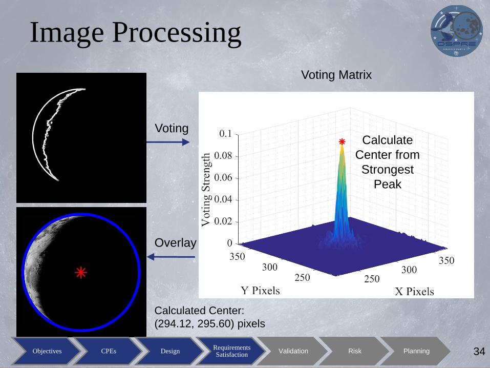
Image Processing
34
Voting Matrix
Calculate
Center from
Strongest
Peak
Calculated Center:
(294.12, 295.60) pixels
Voting
Overlay
Objectives CPEs Design Requirements Satisfaction
Validation Risk Planning

Image Processing
35
67 pixels diameter in a 13 MP (4208 x 3120) image
Objectives CPEs Design Requirements Satisfaction
Validation Risk Planning

Image Processing
36
● Average of 0.7 px error for most
parameters
● Average of 0.5 px error
● Symmetry explains flat
average
Threshold - voting strength kept, lower = less votes kept, higher = more votes kept
±Radius - Plus and minus range of radius to analyze; more information in backup
Objectives CPEs Design Requirements Satisfaction
Validation Risk Planning

Navigation
• Three position algorithms
– require images of Earth, Moon, or both
– most accurate one is chosen at each point in time during
flight
• Run through a data filter to increase accuracy
and compute velocity and error.
37 Objectives CPEs Design Requirements Satisfaction
Validation Risk Planning

Navigation Algorithms
38
Ranging Algorithms
(Earth and Moon)
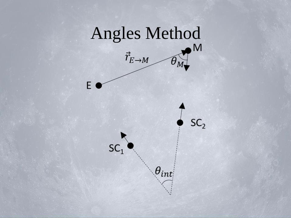
Angles Algorithm
1. Ranging from Earth or
Moon
2. Calculates attitude to
body center.
3. Calculates angular
diameter from edge-
finding and camera
specifications.
4. Calculates position.
1. Calculates attitude to
first body.
2. Calculates attitude to
second body.
3. Propagates second
position from first
position velocity.
4. Calculates first position
from relative geometry.
Objectives CPEs Design Requirements Satisfaction
Validation Risk Planning

Navigation Algorithms
39 Objectives CPEs Design Requirements Satisfaction
Validation Risk Planning

Navigation Kalman Filter
Kalman Filter
• Mitigates error using estimated dynamics and
errors – inherent measurement noise may be high
– dependent on orbit and image processing
• Provides velocity
• Provides error in both position and velocity
40 Objectives CPEs Design Requirements Satisfaction
Validation Risk Planning

Navigation Kalman Filter
41
Initialization
Observation
Integration
Time Update
Computation
Estimation
Objectives CPEs Design Requirements Satisfaction
Validation Risk Planning

Navigation Kalman Filter
42 Objectives CPEs Design Requirements Satisfaction
Validation Risk Planning
Initialization
Observation
Integration
Time Update
Computation
Estimation

Navigation Kalman Filter
43 Objectives CPEs Design Requirements Satisfaction
Validation Risk Planning

Navigation Kalman Filter
44 Objectives CPEs Design Requirements Satisfaction
Validation Risk Planning

Navigation
45
Requirement OSPRE Design Verification
FR1.1
DR1.1.3 Computation of the angles between the simulated
spacecraft, Earth, and Moon
3 Positional
algorithms Software Test
DR1.1.4 Include the estimation of the range to the Earth
and Moon from the simulated spacecraft
3 Positional
algorithms Software Test
DR1.1.5 Output the computed state vector update and error
in the ECI reference frame. Kalman Filter Software Test
FR1.2 DR1.2
Computation of the position and the position error
of the simulated spacecraft and be capable of
achieving an error of less than 1000km from actual
position.
3 Positional
algorithms and
Kalman Filter
Software Test
FR1.3 DR1.3
Computation of the velocity and velocity error of
the simulated spacecraft and be capable of
achieving an error of less than 250 m/s from actual
velocity.
Kalman Filter Software Test
Objectives CPEs Design Requirements Satisfaction
Validation Risk Planning

Verification and Validation
46 Objectives CPEs Design Requirements Satisfaction
Validation Risk Planning

Testing
47
1. Operational Systems Test • FR 1.1 - State Vector
Calculation
• FR 1.2 - Position Accuracy
• FR 1.3 - Velocity Accuracy
• FR 1.4 - ESM Angle
• FR 1.5 - Solution Validity
• FR 2.5 - Data Collection
• Satisfies customer
requirement
Takeaway - Test is Vital for Project Success
Objectives CPEs Design Requirements Satisfaction
Validation Risk Planning

Key Testing Aspects
RANGING METHOD:
How large does the celestial body appear in the image?
ANGLES METHOD:
How large does the celestial body appear in the image?
Where exactly does the celestial body appear in the
image?
48 Objectives CPEs Design Requirements Satisfaction
Validation Risk Planning

Operational Systems Testing
• Will allow position calculation
• Here’s what it looks like:
49 Objectives CPEs Design Requirements Satisfaction
Validation Risk Planning

Operational Systems Testing
50 Objectives CPEs Design Requirements Satisfaction
Validation Risk Planning

Operational Systems Test
51 Objectives CPEs Design Requirements Satisfaction
Validation Risk Planning

LightBox
52 Objectives CPEs Design Requirements Satisfaction
Validation Risk Planning
Light Panel
Moon Cut-out
(Sheet Metal)
Alignment
Panel
(Sheet Metal)
Laser
Range
Finder

Camera Mount
53
Geared
Tripod
Mount
Objectives CPEs Design Requirements Satisfaction
Validation Risk Planning
OSPRE
System
Laser
Range
Finder
Laser
Target
(Acrylic)
OSPRE
Camera

Testing CONOPS
54 Objectives CPEs Design Requirements Satisfaction
Validation Risk Planning

Operational Systems Testing Error
OBJECTIVE Make test-attributed error lesser than 5% (50 km scaled) for all mission test cases to allow for statistically significant OSPRE position error quantification
IMPLICATIONS For the worst-case mission scenario the test must introduce less than 0.0221% error (50 km position error over 226,030 km scaled distance)
55 Objectives CPEs Design Requirements Satisfaction
Validation Risk Planning

Operational Systems Testing Error
56 Objectives CPEs Design Requirements Satisfaction
Validation Risk Planning

Operational Systems Testing Error
57
Source Associated
Error Source
Human Error
Margin
Lightbox
Pointing ± 0.2˙
Alignment error
due to equipment x 1.5 margin
Camera
Pointing ± 0.007˙ 0.5 pixel error x 1.1 margin
Calipers ± 0.025 mm Advertised
equipment error x 1.5 margin
Steel Tape
Measure ± 1.1 mm
Advertised
equipment error x 1.5 margin
Laser Ranger ± 1.5 mm Advertised
equipment error x 1.2 margin
Center Finding ± 0.05 mm Machining
accuracy x 1.2 margin
Objectives CPEs Design Requirements Satisfaction
Validation Risk Planning

Operational Systems Testing Error
Worst Case Error
Scenario
5,000,000 trials
Gaussian randomized error
< 50 km Error Goal 79.9% of the time
< 100 km Error 98.31% of the time
58 Objectives CPEs Design Requirements Satisfaction
Validation Risk Planning

Validation & Verification
Takeaway
• Test setup currently has an 79.9% chance of
providing a statistically significant state error
quantification – Validates FR 1.1, 1.2, 1.3, 1.4, & 1.5
• Test setup satisfies the customer requirement of
developing a system-level testbed
• Sub-system level tests will validate all other
sub-system level functional requirements
59 Objectives CPEs Design
Requirements Satisfaction
Validation Risk Planning

Risk Analysis
60 Objectives CPEs Design Requirements Satisfaction
Validation Risk Planning

Risk Matrix
61 Objectives CPEs Design Requirements Satisfaction
Validation Risk Planning

Risk Analysis
62 Objectives CPEs Design Requirements Satisfaction
Validation Risk Planning

Risk Analysis
63 Objectives CPEs Design Requirements Satisfaction
Validation Risk Planning

Project Planning
64 Objectives CPEs Design Requirements Satisfaction
Validation Risk Planning

Organizational Chart
65 Objectives CPEs Design Requirements Satisfaction
Validation Risk Planning

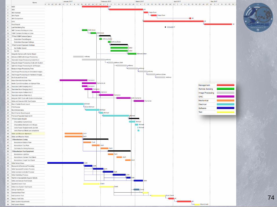
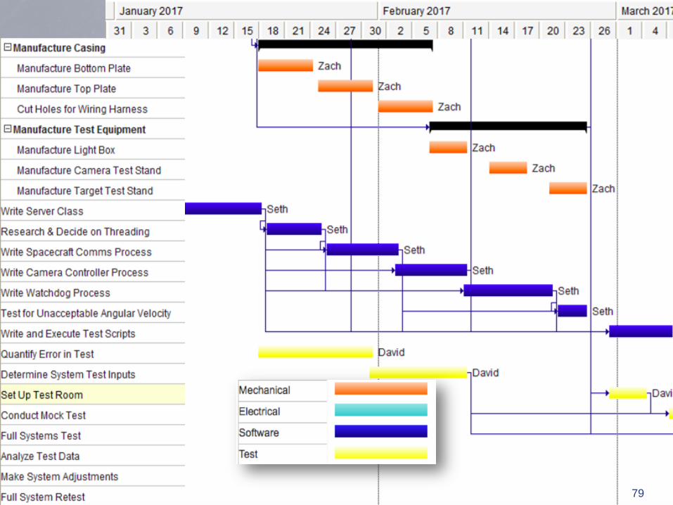
Work Breakdown Structure
66

Work Breakdown Structure
67
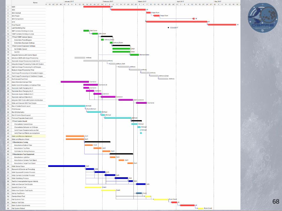
68

69

70 70

71

72

73 73
74

75

76 76

77

78
79 79

80

81

82 82

54.8%
$0
$1,000
$2,000
$3,000
$4,000
$5,000
$6,000
Total
Margin
In-Use
Budget
83
$1,600
$450
$1,750
$1,200
54.4%
42.2%
51.8%
22.9%
$0
$200
$400
$600
$800
$1,000
$1,200
$1,400
$1,600
$1,800
$2,000
Testing Mechanical Electrical Optics
Bu
dg
et
Objectives CPEs Design Requirements Satisfaction
Validation Risk Planning

Test Plan
84
Test Equipment &
Facilities
Personnel Date
Software Test: Does the data
filter, pre-processing, and image
processing work within the system
software architecture as expected?
None S. Zegelstein,
A. Torres, C.
Maywood, D.
Walden
2/27/16 - 3/6/16
Hardware Test: Does the system
turn on and complete all nominal
functions upon initialization while
remaining within power
requirements?
Oscilloscope,
ESD
workstation,
power supply
M. Ricciardi,
D. Richards,
D. Walden
2/27/16 - 3/6/16
Problem Simulation Test: Can
the system deal with issues with
temperature, spacecraft inputs,
bad photos, glare, etc?
None D. Walden, R.
Cutter
3/6/16 - 3/13/16
Operational Systems Test: Does
the system produce a solution with
the required accuracy?
Dark room,
light box, test
stand
D. Walden, R.
Cutter, Z.
Folger
3/13/16 -
3/24/16
Objectives CPEs Design Requirements Satisfaction
Validation Risk Planning

Test Equipment & Facilities
85
Facility / Equipment Resource
Geared Tripod Head Purchased
Tripods Borrowed from team members & and test
facility
Simulated Celestial Body Machined in Aerospace Machine Shop
Light Panel Purchased
Measurement Tools Purchased and borrowed from test
facility/ITLL/aerospace department
Simulated Spacecraft Computer Purchased a ZedBoard
Test Stands Machined in Aerospace Machine Shop
Dark Room ECEE 2B49A headed by Dr. Cash, who
has granted permission for OSPRE to use
the facility next semester
Objectives CPEs Design Requirements Satisfaction
Validation Risk Planning

References
1. Samtec, "0.40mm Razor Beam LP Ultra Fine Pitch Socket Strip," 1 October 2016. [Online]. Available:
https://www.samtec.com/products/ss4.
2. Analog Devices, "ADT7311: Automotive, ±0.5°C Accurate, 16-Bit," Analog Devices, Norwood, MA, 2011.
3. Future Technology Devices Intl., "FT234XD USB TO BASIC UART IC V1.2," FTDI Ltd., Glasgow, UK, 2015.
4. Richtek, "RT7258 8A, 24V, 600kHz Step-Down Converter," Richtek Technology Corp., San Jose, 2013.
5. Intrinsyc Technologies Corp., "Open-Q 410 Development Kit BSP Programming Guide V1.0," Intrinsyc Technologies
Corp., Vancouver, BC, 2016.
6. Intrinsyc Technologies Corp., "Intrinsyc Open-QTM 410 (APQ8016) Carrier Board Design Guide R1.3," Intrinsyc
Technologies Corp., Vancouver, BC, 2016.
7. Intrinsyc Technologies Corp., "Open-QTM 410 Development Kit based on the Qualcomm® SnapdragonTM 410 processor
(APQ8016) User Guide R1.3," Intrinsyc Technologies Corp., Vancouver, BC, 2016.
8. Intrinsyc Technologies Corp., "Intrinsyc Open-QTM 410 (APQ8016) Development Kit Technical Note 18: Camera Board
Design Guide R1.0," Intrinsyc Technologies Corp., Vancouver, BC, 2016.
9. Intrinsyc Technologies Corp., "Open-Q 410 Development Carrier Board Electrical Schematics 8May2015," Intrinsyc
Technologies Corp., Vancouver, BC, 2015.
10. Intrynsic Technologies Corp., "APQ-8016 Open-Q SOM Electrical Schematics 26Mar2015," Intrynsic Technologies Corp.,
Vancouver, BC, 2016.
86 Objectives CPEs Design Requirements Satisfaction
Validation Risk Planning

Thank You
87
Paige Arthur PM
Ryan Cutter Systems
Seth Zegelstein Software
Michael Ricciardi Electrical
Anthony Torres Image
Processing
Cameron
Maywood
Navigation
Dylan Richards Remote Sensing
Zach Folger Mechanical
David Walden Testing

BACKUP SLIDES

Electrical/Software Backup Slides

OSPRE Electrical Architecture System-on-Module Functional Capabilities

OSPRE Electrical Architecture Carrier Board Functional Block

OSPRE Electrical Architecture Serial Debug Interface (UART)

CONNECTOR PINOUT
PARNO TE 1589426 15Pos
REFDES CONTACT SIGNAL NAME
J1 1 12VDC
J1 2 12VDC
J1 3 12VDC_RTN
J1 4 12VDC_RTN
J1 5 UART_USB_DATA_N
J1 6 UART_USB_DATA_P
J1 7 UART_USB_GND
J1 8 UART_USB_VBUS
J1 9 CHASSIS_GND
J1 10 SPI_CLK
J1 11 SPI_SS
J1 12 SPI_DATA_MOSI
J1 13 SPI_DATA_MISO
J1 14 I2C_SCL
J1 15 I2C_SDA
OSPRE Electrical Architecture External Interface & Pin-Out
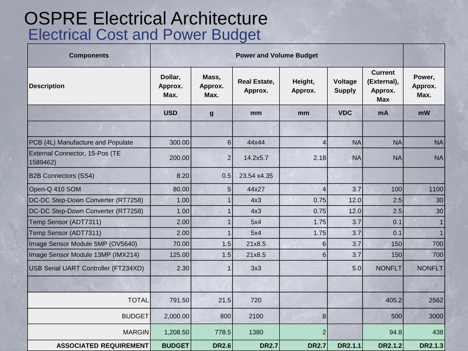
OSPRE Electrical Architecture Electrical Cost and Power Budget
Components Power and Volume Budget
Description
Dollar,
Approx.
Max.
Mass,
Approx.
Max.
Real Estate,
Approx.
Height,
Approx.
Voltage
Supply
Current
(External),
Approx.
Max
Power,
Approx.
Max.
USD g mm mm VDC mA mW
PCB (4L) Manufacture and Populate 300.00 6 44x44 4 NA NA NA
External Connector, 15-Pos (TE
1589462) 200.00 2 14.2x5.7 2.18 NA NA NA
B2B Connectors (SS4) 8.20 0.5 23.54 x4.35
Open-Q 410 SOM 80.00 5 44x27 4 3.7 100 1100
DC-DC Step-Down Converter (RT7258) 1.00 1 4x3 0.75 12.0 2.5 30
DC-DC Step-Down Converter (RT7258) 1.00 1 4x3 0.75 12.0 2.5 30
Temp Sensor (ADT7311) 2.00 1 5x4 1.75 3.7 0.1 1
Temp Sensor (ADT7311) 2.00 1 5x4 1.75 3.7 0.1 1
Image Sensor Module 5MP (OV5640) 70.00 1.5 21x8.5 6 3.7 150 700
Image Sensor Module 13MP (IMX214) 125.00 1.5 21x8.5 6 3.7 150 700
USB Serial UART Controller (FT234XD) 2.30 1 3x3 5.0 NONFLT NONFLT
TOTAL 791.50 21.5 720 405.2 2562
BUDGET 2,000.00 800 2100 8 500 3000
MARGIN 1,208.50 778.5 1380 2 94.8 438
ASSOCIATED REQUIREMENT BUDGET DR2.6 DR2.7 DR2.7 DR2.1.1 DR2.1.2 DR2.1.3

Design Drivers: FR 1.0 - Accuracy FR 2.0 - Volume Camera Specs: • 8.5 x 8.5 x 5.3 mm lens
package • 13MP sensor (IMX214) • FOV = 60° x 45° • ~70 pixels/°
OSPRE Electrical Architecture
Imaging Sensor

Further Software Architecture Detail
•OSPRE needs multiple processes in order to take
advantage of two separate cpu’s
•The OSPRE system was designed to be modular
– If the camera or S/C change only the Camera
Controller or SCComms process need to change
•All processes will be derived from an virtual server
class containing the common elements of all
OSPRE’s server processes

OSPRE will run on 2 Linux OS CPUs. Processes will be split between:
• ZedBoard (Simulated Spacecraft) [2 core]
• Onboard SOM processor [4 core]
OSPRE consists of 5 major processes:
Zedboard will simulate the spacecraft by:
• Providing all necessary inputs (Time, Quaternion, Angular Velocity, etc.)
• Reading in OSPRE results and updates. (State Vector + Error, Status, Pointing Adjustments)
OSPRE Software Architecture
Overview
• Camera Controller
• Image Processing
• Navigation
• S/C Comms
• WatchDog

Software Design - Startup
•More Complicated due to using two different CPUs
•When the OSPRE sensor package receives power,
the microprocessor onboard will turn on and boot
up Linux OS. On startup, a script will be run to start
our OSPRE system processes residing on SOM.
•OSPRE will have another startup script for the Zed
Board to start the OSPRE server processes on the
Zed Board

Software Design - Server Process 1
•All processes will listen at a defined port number for new
connection requests
•Each process will have a defined number of connections
–All processes will be accepting connections
–Processes will connect to each other in a predefined
manner
–Only WatchDog will be written to support N connections

Software Design - Server Process 2
•Servers will be using a call to select and registering for read and
write events when interested in them
•The select call will be using timeouts to allow for the handling of
error cases
•SIGPIPES are ignored so that the Server doesn’t quit when the
client disconnects
•In the event that two processes lose a connection, the process
acting as the client will attempt to reconnect to the process
acting as the Server

Software Design - Server Process 3
-OSPRE Servers will not follow the classic Server to Client relationship. OSPRE Servers
will act as both a Server and Client.
–All Processes will be listening on a dedicated socket for connection requests (Typical
Server). Specific processes will connect to others processes because they need
information from said process (Typical Client).
-An abstract OSPRE server class will be written in C++ from which all process classes
will be derived from.
–The server class will contain a virtual run method, which each individual process class
will implement.
–The Server class will implement generic methods that all derived classes need such
as init(), openServerSocket(), and connectToServer()
–The Server class will be built by composition and have instances of other classes to
deal with intra-process communication (details below)

Watchdog
Navigation
Camera
Control
Image
Processing
Camera
Temperature
Sensors
Health &
Status
Response
Health &
Status
Request
Operating
Camera
Temperature
?
How’s it
goin’?
S’all Good
Here
We
Guchi
Unresponsive
Process:
1. Try to
Reconnect
2. Kill &
Restart
OSPRE
OSPRE Software Architecture
Watchdog


Software Design - Error Cases
Error: Process Failure
Action: Restart OSPRE system (Power on/ Off), (S/C responsibility)
Error: GNC cannot achieve accurate solution to within error bounds
Action: Report solution to current error
Error: Image Processing cannot find body (Earth / Moon) in the picture
Action: Report status to with error message S/C, attempt to change Camera
setting, keep trying
Error: Not pointing at the right targets (Earth / Moon)
Action: Send additional pointing request to S/C and wait

Software Design - Shutdown
•More Complicated due to using two different
CPUs
•Cut power to OSPRE sensor package
•Send SIG_KILL signals to processes on ZedBoard

Image Processing Backup Slides

Image Processing
● Circular Hough
Transform Overview
● Celestial body outline
of radius R
○ Outline found with
gradient of image
○ Edge could also
be an arc (for
phased bodies)

Image Processing
● Move along edge
● Draw circle of votes
with a radius R
● Keep these votes in a
matrix, called the
accumulator matrix

Image Processing
● Keep voting along
edge
● These votes will then
overlap at the center

Image Processing
● The point with the
most votes, the most
overlap, is the
calculated center
● This finds both the
center and the best
radius at the same
time

Image Processing
● A more efficient
method uses normal
vectors
● Along the same
celestial body outline,
draw a normal vector
outwards
○ The Moon or Earth
being lighter than
space allows for
the direction to be
determined

Image Processing
● Draw a line from the normal
vector
● Only draw a portion of the line
around the guessed radius
● Further, each point on the line
has an associated phase
○ More on phase encoding
further on
● This method decreases
computation time, and
increases accuracy

Image Processing
● Keep moving around
edge and drawing
normal vectors, and
the subsequent radius
guesses

Image Processing
● The overlap of these guesses
indicate the center
● The phase constructively
interferes at the center, which
corresponds to a radius
● This again finds the center
and the diameter of the
celestial body
● This also works for phases,
but with less votes
○ Increasing the sensitivity of
the algorithm compensates

Image Processing
Kept Above Threshold
Discarded Below Threshold Voti
ng S
tren
gth
Votes are kept or discarded based on a strength threshold.
Decreasing the threshold potentially allows for more noise, but
also allows for more sensitive analysis with lower strength.

Image Processing
Atherton, T.J., Kerbyson, D.J., The Coherent Circle Hough
Transform, 1993. http://www.bmva.org/bmvc/1993/bmvc-93-
027.pdf
http://physics.tutorcircle.com/waves/wave-interference.html
● Each radius guess, for each point
on an edge, has phase encoding
associated
○ Using Euler’s Formula, this
moves the voting matrix into
the complex domain
● The different phases will then
constructively interfere for common
radii, and destructively interfere
otherwise
● This encoding provides the
coherence of the circle finding
algorithm
● Phase encoding also makes the
algorithm more robust as noise will
tend to destructively interfere as
there is no order
z = e𝞿𝚤
Phase

Image Processing
• We use a Sobel Kernel to find the edges of an image
• Performed with Kernel Convolution – An image is simply a
large matrix – Kernel matrix is ‘moved’
through matrix to calculate new values based on neighbor values
Sobel Operator:
Basic Kernel Convolution Idea:
https://docs.gimp.org/en/plug-in-convmatrix.html
http://edge.kitiyo.com/2009/intro/relevance-of-the-project.html
Result:

Image Processing
● Top-down view of voting
accumulator matrix
● Side graphs are 2D views
of the matrix
● Majority of the analyzed
image can be
approximated as zero
○ Allows for precise
locations to be found

Image Processing

Image Processing
● Rough faux Moon created with
plaster
● Coherent Circular Hough
Transform robust enough to
handle even unrealistic
scenarios
● Timestamp is included for the
analysis, with the noise seen in
the voting, but the algorithm still
finds the circular center

● Majority average of
8 px error in radius
● Spikes as radius
estimate range
approaches
celestial body
radius (will not ever
be this far off in
estimation)
● Decreases to <8 px
error, but with
increased solution
sensitivity
Threshold - voting strength kept, lower = less votes kept, higher = more votes kept
±Radius - Plus and minus range of radius to analyze; more information in backup
OSPRE Image Processing
Radius Determination Error

Diffraction Limit
• Degree/Pixel = ~0.0143° • Diffraction Limit =
0.01475° (blue) 0.02766° (red) • Diffraction limited, but
well matched

Image Processing
• Center finding
• Diameter finding
Navigation
• Three position algorithms
–require images of Earth, Moon, or both
–most accurate one is chosen at each point in time during flight
• Run through a data filter to increase accuracy and compute velocity

Navigation Backup Slides

Error Angles

Ranging Method

Ranging Method

Ranging Method

Ranging Method

Ranging Method

Angles Method

Angles Method
Angles Method

Angles Method

Angles Method

Angles Method

Angles Method

Angles Method

Velocity Algorithm - Curve Fitting Method
Technique: • Curve fit the X, Y, & Z position
data individually • Differentiating each of the
position curves individually provides X, Y, & Z velocity data
Drawbacks: • Reports velocity data for the
previous hour once at the end of each hour
• Need a lot of data points with small timesteps in between to be accurate

STK vs. 3-Body Trajectory


OSPRE Navigation
Position Error Without Kalman Filter

OSPRE Navigation
Position Error With Kalman Filter
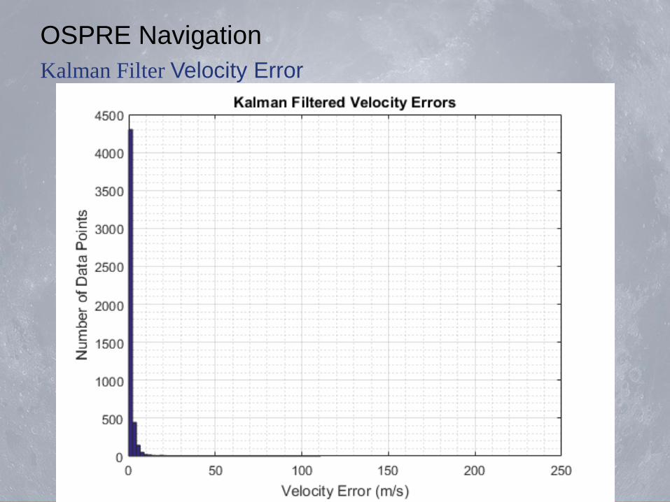
OSPRE Navigation
Kalman Filter Velocity Error


OSPRE Navigation
Kalman Filter Position Error

OSPRE Navigation
Kalman Filter Velocity Error


TESTING BACKUP SLIDES

Test Scope

Test Scope Test Scope

Test Scope

Mission Testing
Primary Objective: Quantify the OSPRE system’s
position error and subsequent velocity error
throughout the mission.
Hypothesis: The OSPRE system meets error
requirements throughout all key mission stages.
Secondary Objective: Ensure that the OSPRE system
can operate autonomously and behaves as expected.
Hypothesis: The OSPRE system operates autonomously
and as expected.

Mission Testing
Primary Objective: Quantify the OSPRE system’s
position error and subsequent velocity error
throughout the mission.
Primary Design Driver: Prioritize the reduction of error
introduced by the test setup
Result: Engineer a high-accuracy, simple testing
solution that allows team OSPRE to test all key mission
stages.

Mission Testing Facility Layout

Simulated S/C Computer ZedBoard
Image Credit: www.zedboard.org

Mission Testing Manipulation Camera Pointing

Mission Testing Manipulation Lightbox Pointing

Mission Testing Error Pointing Method

Mission Testing Error Alignment Method

Mission Testing Error Alignment Method

Mission Testing Error Alignment Method


Mission Testing Error Lightbox Pointing Error Implications
Earth Flattening
Factor
Moon Flattening
Factor

Mission Testing Error Camera Pointing Error
Procedure:
1. Take image of alignment target
2. Process image to find location of center of target
relative to center of image frame
3. Adjust camera pointing
4. Repeat until centers are aligned

Pointing Accuracy Error Mitigation:
• Laser pointers running parallel to lightbox pointing
vector
• Telescopic mounts allow for high precision pointing
adjustments
• Alignment test procedure: confident to within ± 0.2˙
accuracy
• Utilize image capture capability to improve camera
pointing accuracy to sub-pixel pointing error
Operational Systems Testing Error

Tool Model Accuracy
Calipers Glow Geek Digital
Calipers ±0.025 mm
Steel Tape Measure Hultafors Tape
Measure ± 1.1 mm
Laser Range Finder Distance Master 60 ±1.5 mm
Distance / Dimensional Measurement Error
Operational Systems Testing Error
Sources

Center Finding Accuracy:
Dependent on rod mounting accuracy due to hole
location uncertainty of ± 0.025 mm
Mounting hole
uncertainty Center
uncertainty
Operational Systems Testing Error

Next Steps
Improved Simulation Fidelity • Additional human error contributions • More constrained measurement errors
Reduce Test-Attributed Error Contribution
• Pointing accuracy improvement

Finance Backup Slides

Testing Budget
176
Subsystem Item Quantity Cost
Testing
Laser Range Finder 1 $130.00 Calipers 1 $25.00
Light Panel 1 $100.00 Aluminum Sheet 2 $80.00 Laser Pointer 2 $60.00
Geared Tripod Head 1 $200.00
Digital Level 1 $50.00
Laser Pointer Mount 2 $60.00 Mounting Materials 1 $50.00 Texture Materials 1 $20.00 Lightbox Legs 1 $20.00 Phase Cutouts 1 $50.00
Alignment Rods 1 $25.00
Subsystem Budget: $1,600.00
Subsystem Total:
$870.00
Subsystem In-Use :
54.4%
Subsystem Margin:
45.6%

Mechanical Budget
177
Subsystem Item Quantity Cost
Mechanical
Aluminum Encasing 1 $10.00
Plywood and Misc 1 $40.00
Misc Building Hardware 1 $20.00
Black Polycarbonate 5 $20.00
Cast Aluminum Base Plate 1 $100.00
Subsystem Budget: $450.00
Subsystem Total:
$190.00
Subsystem In-Use :
42.2%
Subsystem Margin:
57.8%

Electrical Budget
178
Subsystem Item Quantity Cost
Electrical
Snapdragon OpenQ 410 Development Kit 1 $299.00
ZedBoard 1 $475.00 PCB 1 $100.00
15 MDSub Connector 1 $25.00 Voltage Regulators 4 $2.00 Thermocouples 2 $5.00
Subsystem Budget: $1,750.00
Subsystem Total:
$906.00
Subsystem In-Use :
51.8%
Subsystem Margin:
48.2%

Optics Budget
179
Subsystem Item Quantity Cost
Optics
13MP Camera 1 $125.00
Sony FCB-MA130 2 $150.00
Subsystem Budget: $1,200.00
Subsystem Total:
$275.00
Subsystem In-Use :
22.9%
Subsystem Margin:
77.1%