osi network layer osi layer 3 - university of babylon · identify the role of the network layer, as...
TRANSCRIPT

© 2007 Cisco Systems, Inc. All rights reserved. Cisco Public ١
OSI Network LayerOSI Layer 3
Network Fundamentals – Chapter 5

٢© 2007 Cisco Systems, Inc. All rights reserved. Cisco Public
Objectives� Identify the role of the Network Layer, as it describes
communication from one end device to another end devi ce
� Examine the most common Network Layer protocol , Internet Protocol (IP) , and its features for providing connectionless and best-effort service
� Understand the principles used to guide the division or grouping of devices into networks
� Understand the hierarchical addressing of devices and how this allows communication between networks
� Understand the fundamentals of routes , next hop addresses and packet forwarding to a destination network

٣© 2007 Cisco Systems, Inc. All rights reserved. Cisco Public

٤© 2007 Cisco Systems, Inc. All rights reserved. Cisco Public
Network Layer Protocols and Internet Protocol (IP)� Define the basic role of the Network Layer in data
networks

٥© 2007 Cisco Systems, Inc. All rights reserved. Cisco Public
Layer 3 uses four basic processes:
� Addressing
� Encapsulation
� Routing
� Decapsulation

٦© 2007 Cisco Systems, Inc. All rights reserved. Cisco Public
1- Addressing
� First, the Network layer must provide a mechanism foraddressing these end devices. If individual pieces of data are to be directed to an end device, that device must have a unique address.
� In an IPv4 network, when this address is added to a device, the device is then referred to as a host .

٧© 2007 Cisco Systems, Inc. All rights reserved. Cisco Public
2- Encapsulation
Second, the Network layer must provide encapsulation.
� During the encapsulation process, Layer 3 receives the Layer 4 PDU and adds a Layer 3 header, or label, to create the Layer 3 PDU. When referring to the Network layer, we call this PDU a packet .
� Layer 4 PDU + Layer 3 header, or label = packet
� When a packet is created, the header must contain, among other information, the destination address. The Layer 3 header also contains the source address.

٨© 2007 Cisco Systems, Inc. All rights reserved. Cisco Public
3- Routing
Next, the Network layer must provide services to “direct”these packets to their destination host. The source and destination hosts are not always connected to the same network. In fact, the packet might have to travel through many different networks. Along the way, each packet must be guided through the network to reach its final destination. Intermediary devices that connect the networks are called routers . The role of the router is to select paths for and direct packets toward their destination. This process is known as routing .

٩© 2007 Cisco Systems, Inc. All rights reserved. Cisco Public
Network Layer Protocols
Protocols implemented at the Network layer include:
� Internet Protocol version 4 (IPv4)
� Internet Protocol version 6 (IPv6)
� Novell Internetwork Packet Exchange (IPX)
� AppleTalk
� Connectionless Network Service (CLNS/DECNet)

١٠© 2007 Cisco Systems, Inc. All rights reserved. Cisco Public
� Basic characteristics of the IPv4 protocol
�Internet Protocol IPv4 was designed as a protocol with low overhead . It provides only the functions that are necessary to deliver a packet from a source to a destination over an interconnected system of networks .

١١© 2007 Cisco Systems, Inc. All rights reserved. Cisco Public
Connectionless Service
� An example of connectionless communication is sending a letter to someone without notifying the recipient in advance, see next figure. Connectionless data communications works on the same principle. IP packets are sent without notifying the end host that they are coming.
� Connection-oriented protocols , such as TCP, require that control data be exchanged to establish the connection as well asadditional fields in the PDU header.
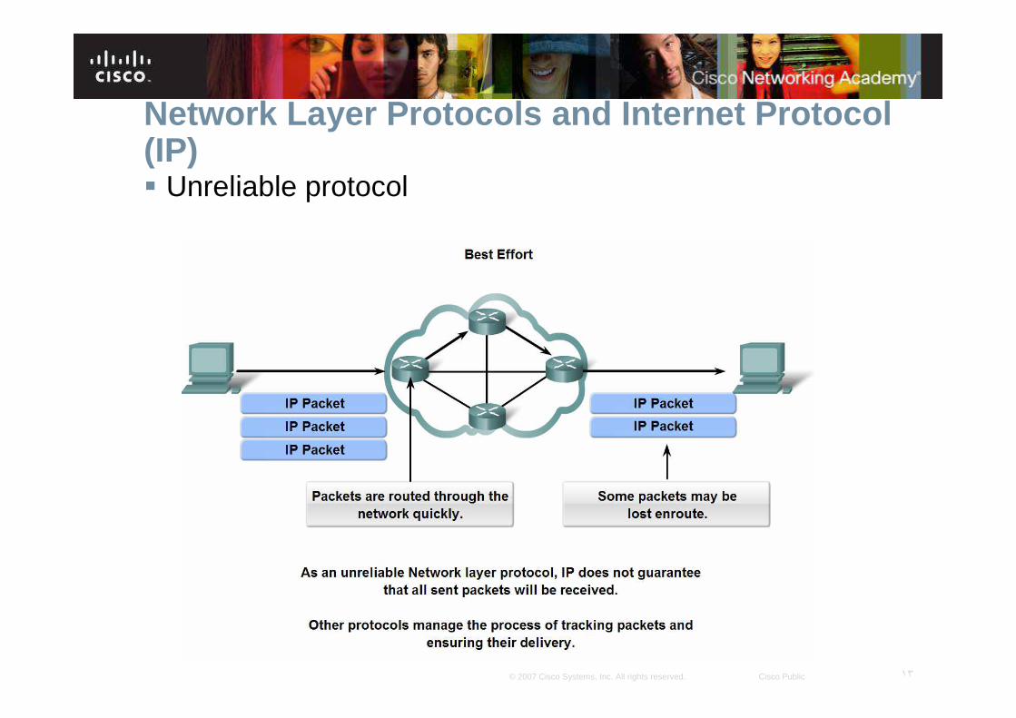
� Connectionless packet delivery may, however, result in packets arriving at the destination out of sequence . If out-of-order or missing packets create problems for the application using the data, then upper layer services will have to resolve these issues.

١٢© 2007 Cisco Systems, Inc. All rights reserved. Cisco Public
Network Layer Protocols and Internet Protocol (IP)� Describe the implications for the use of the IP protocol
as it is connectionless
١٣© 2007 Cisco Systems, Inc. All rights reserved. Cisco Public
Network Layer Protocols and Internet Protocol (IP)� Unreliable protocol

١٤© 2007 Cisco Systems, Inc. All rights reserved. Cisco Public
Network Layer Protocols and Internet Protocol (IP)� Use of the IP as it is media independent

١٥© 2007 Cisco Systems, Inc. All rights reserved. Cisco Public
� There is, however, one major characteristic of the media that the Network layer considers: the maximum size of PDU that each medium can transport. This characteristic is referred to as the Maximum Transmission Unit (MTU).
� intermediary device - usually a router - will need to split up a packet when forwarding it from one media to a media with a smaller MTU. This process is called fragmenting the packet or fragmentation.

١٦© 2007 Cisco Systems, Inc. All rights reserved. Cisco Public
Network Layer Protocols and Internet Protocol (IP)� Segments are encapsulated as packets

١٧© 2007 Cisco Systems, Inc. All rights reserved. Cisco Public
� Header fields in the IPv4 protocol

١٨© 2007 Cisco Systems, Inc. All rights reserved. Cisco Public
� IP Source Address
� IP Destination Address
� Time-to-Live (TTL)
� Type-of-Service (ToS)
� Protocol
� Fragment Offset

١٩© 2007 Cisco Systems, Inc. All rights reserved. Cisco Public
IP Destination Address
� The IP Destination Address field contains a 32-bit binary value that represents the packet destination Network layer host address.
IP Source Address
� The IP Source Address field contains a 32-bit binary value that represents the packet source Network layer host address.

٢٠© 2007 Cisco Systems, Inc. All rights reserved. Cisco Public
� The Time-to-Live (TTL) is an 8-bit binary value that indicates the remaining "life" of the packet .
� The TTL value is decreased by at least oneeach time the packet is processed by a router (that is, each hop). When the value becomes zero, the router discards or drops the packet and it is removed from the network data flow. This mechanism prevents packets that cannot reach their destination from being forwarded indefinitely between routers in a routing loop.
٢١© 2007 Cisco Systems, Inc. All rights reserved. Cisco Public
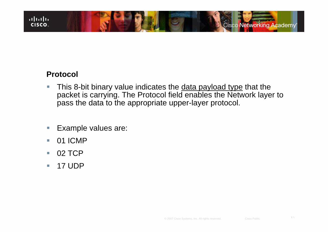
Protocol
� This 8-bit binary value indicates the data payload type that the packet is carrying. The Protocol field enables the Network layer to pass the data to the appropriate upper-layer protocol.
� Example values are:
� 01 ICMP
� 02 TCP
� 17 UDP

٢٢© 2007 Cisco Systems, Inc. All rights reserved. Cisco Public
Type-of-Service
� The Type-of-Service field contains an 8-bit binary value that is used to determine the priority of each packet . This value enables a Quality-of-Service (QoS) mechanism to be applied to high priority packets, such as those carrying telephony voice data .

٢٣© 2007 Cisco Systems, Inc. All rights reserved. Cisco Public
Fragment Offset
� As mentioned earlier, a router may have to fragment a packet when forwarding it from one medium to another medium that has a smaller MTU. When fragmentation occurs, the IPv4 packet uses the “Fragment Offset field ” and the “MF flag ” in the IP header to reconstruct the packet when it arrives at the destination host. The fragment offset field identifies the order in which to place the packet fragment in the reconstruction .
٢٤© 2007 Cisco Systems, Inc. All rights reserved. Cisco Public
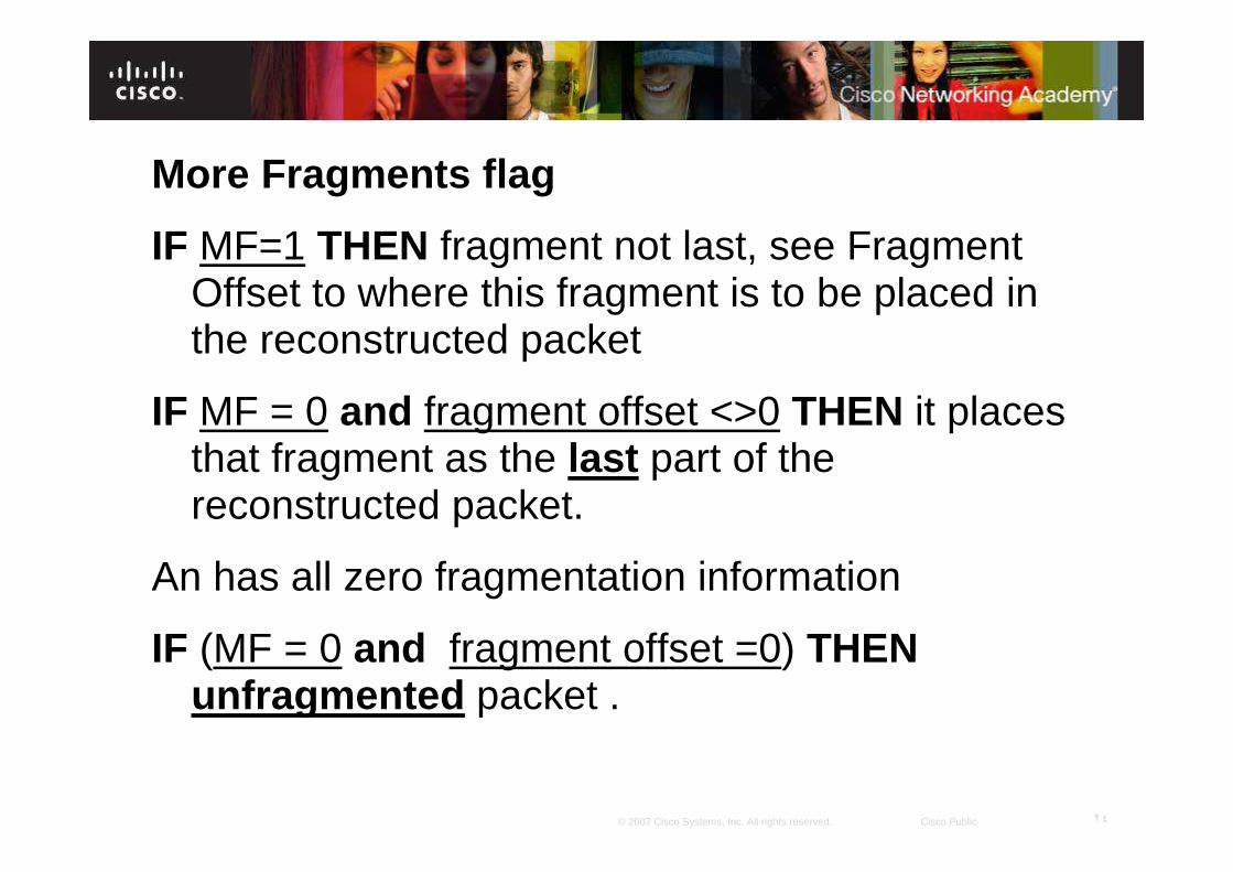
More Fragments flag
IF MF=1 THEN fragment not last, see Fragment Offset to where this fragment is to be placed in the reconstructed packet
IF MF = 0 and fragment offset <>0 THEN it places that fragment as the last part of the reconstructed packet.
An has all zero fragmentation information
IF (MF = 0 and fragment offset =0) THENunfragmented packet .

٢٥© 2007 Cisco Systems, Inc. All rights reserved. Cisco Public
Don't Fragment flag
� The Don't Fragment (DF) flag is a single bit in the Flag field that indicates that fragmentation of the packet is not allowed.
IF DF=1 THEN fragmentation of this packet is NOT permitted.
If a router needs to fragment a packet to allow it to be passed downward to the Data Link layer but the DF bit is set to 1, then the router will discard this packet.
� See your material for other fields and example.

٢٦© 2007 Cisco Systems, Inc. All rights reserved. Cisco Public
Grouping Devices into Networks and Hierarchical Addressing� List several different reasons for grouping devices into
sub-networks and define several terms used to identify the sub-networks

٢٧© 2007 Cisco Systems, Inc. All rights reserved. Cisco Public
� as our networks grow, they may become too large tomanage as a single network. At that point, we need to divide our network. When we plan the division of the network, we need to group together those hosts with common factors into the same network.
Networks can be grouped based on factors that include:
� Geographic location
� Purpose
� Ownership

٢٨© 2007 Cisco Systems, Inc. All rights reserved. Cisco Public
Grouping Devices into Networks and Hierarchical Addressing� List several ways in which dividing a large network can
increase network performance

٢٩© 2007 Cisco Systems, Inc. All rights reserved. Cisco Public
Broadcast DomainA broadcast is a message sent from one host to all other hosts on the network.

٣٠© 2007 Cisco Systems, Inc. All rights reserved. Cisco Public
� Typically, a host initiates a broadcast when information about another unknown host is required. However, large numbers of hosts generate large numbers of broadcasts that consume network bandwidth. And because every other host has to process the broadcast packet it receives, the other productive functions that a host is performing are also interrupted or degraded.
٣١© 2007 Cisco Systems, Inc. All rights reserved. Cisco Public
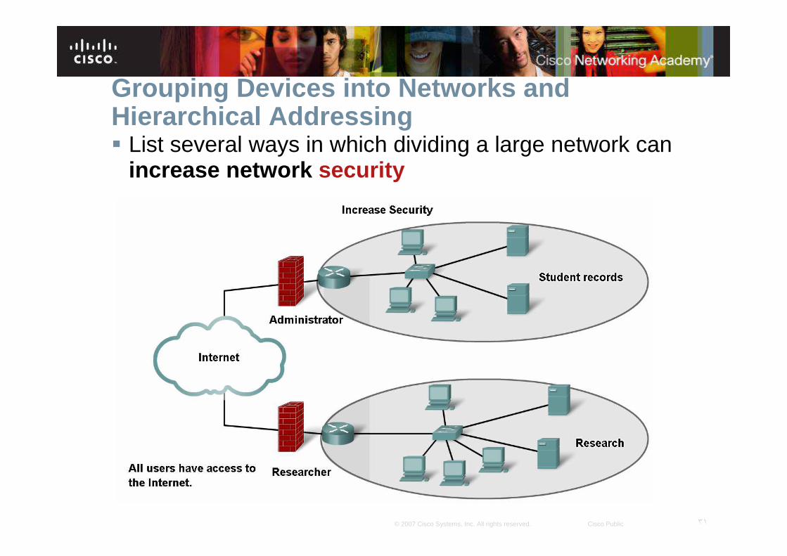
Grouping Devices into Networks and Hierarchical Addressing� List several ways in which dividing a large network can
increase network security

٣٢© 2007 Cisco Systems, Inc. All rights reserved. Cisco Public
Grouping Devices into Networks and Hierarchical Addressing� Explain the communication problems that emerge when
very large numbers of devices are included in one large network

٣٣© 2007 Cisco Systems, Inc. All rights reserved. Cisco Public
� The Internet consists of millions of hosts, each of which is identified by its unique Network layer address. To expect each host to know the address of every other host would impose a processing overhead on these network devices that would severely degrade their performance.
� Dividing large networks so that hosts who need to communicate are grouped together reduces the unnecessary overhead of all hosts needing to know all addresses .
� For all other destinations, the hosts only need to know the address of an intermediary device, to which they send packets for all other destinations addresses. This intermediary device is called a gateway . The gateway is a router on a network that serves as an exit from that network .
� What are common problems with a large network?

٣٤© 2007 Cisco Systems, Inc. All rights reserved. Cisco Public
Common problems with a large network?
�1- performance degradation
�2- security issues
�3- host identification

٣٥© 2007 Cisco Systems, Inc. All rights reserved. Cisco Public
Hierarchical Addressing� Describe how hierarchical addressing solves the
problem of devices communicating across networks of networks

٣٦© 2007 Cisco Systems, Inc. All rights reserved. Cisco Public
A hierarchical address:
� uniquely identifies each host, It also has levels that
� assist in forwarding packets across internetworks,
� To be able to divide networks, we need hierarchical addressing.
Hierarchical Addressing

٣٧© 2007 Cisco Systems, Inc. All rights reserved. Cisco Public
� Hierarchical Network layer addresses, Layer 3 addresses, supply the network portion of the address. Routers forward packets between networks by referring only to the part of the Network layer address that is required to direct the packet toward the destination network.
� By the time the packet arrives at the destination host network, the whole destination address of the host will have been used to deliver the packet.

٣٨© 2007 Cisco Systems, Inc. All rights reserved. Cisco Public

٣٩© 2007 Cisco Systems, Inc. All rights reserved. Cisco Public
Further subdividing networks into smaller networks
� With IPv4 hierarchical addressing, the network portion of the address for all hosts in a network is the same.
� To divide a network, the network portion of the address is extended to use bits from the host portion of the address. These borrowed host bits are then used as network bits to represent the different subnetworkswithin the range of the original network .
� Given that an IPv4 address is 32 bits, when host bits are used to divide a network the more subnetworkscreated results in fewer hosts for each subnetwork. Regardless of the number of subnetworks created however, all 32 bits are required to identify an individual host.

٤٠© 2007 Cisco Systems, Inc. All rights reserved. Cisco Public
� The number of bits of an address used as the network portion is called the prefix length . For example if a network uses 24 bits to express the network portion of an address the prefix is said to be /24.
� In the devices in an IPv4 network, a separate 32-bit number called a subnet mask indicates the prefix .
� For the purposes of explanation, however in this chapter the first 24 bits of an IPv4 address will be used as the network portion.

٤١© 2007 Cisco Systems, Inc. All rights reserved. Cisco Public
� Within a network or a subnetwork, hosts communicate with each other without the need for any Network layer intermediary device.
� When a host needs to communicate with another network , an intermediary device, or router , acts as a gateway to the other network .
Fundamentals of Routes, Next Hop Addresses and Packet Forwarding

٤٢© 2007 Cisco Systems, Inc. All rights reserved. Cisco Public
Fundamentals of Routes, Next Hop Addresses and Packet Forwarding� Describe the role of an intermediary gateway device in
allowing devices to communicate across sub-divided networks

٤٣© 2007 Cisco Systems, Inc. All rights reserved. Cisco Public
� As a part of its configuration, a host has a default gateway address defined. As shown in the figure, this gateway address is the address of a router interface that is connected to the same network as the host .
To communicate with a device on another network, a host uses the address of this gateway, or default gateway, to forward a packet outside the local network.

٤٤© 2007 Cisco Systems, Inc. All rights reserved. Cisco Public
� The router also needs a route that defines where to forward the packet next. This is called the next-hop address . If a route is available to the router, the router will forward the packet to the next-hop router that offers a path to the destination network.

٤٥© 2007 Cisco Systems, Inc. All rights reserved. Cisco Public
� If communication is between hosts in different networks , the local network delivers the packet from the source to its gateway router. The router examines the network portion of the packet destination address and forwards the packet to the appropriate interface. If the destination network is directly connected to this router, the packet is forwarded directly to that host. If the destination network is not directly connected, the packet is forwarded on to a second router that is the next-hop router .
� Host � gateway (router) � Host
� Host � Gateway (Router) � another Router � ……
The packet forwarding then becomes the responsibility of this second router. Many routers or hops along the way may process the packet before reaching the destination.

٤٦© 2007 Cisco Systems, Inc. All rights reserved. Cisco Public
Fundamentals of Routes, Next Hop Addresses and Packet Forwarding� Trace the steps of an IP packet as it traverses
unchanged via routers from sub network to sub-network

٤٧© 2007 Cisco Systems, Inc. All rights reserved. Cisco Public
� The gateway, also known as the default gateway , is needed to send a packet out of the local network. If the network portion of the destination address of the packet is different from the network of the originating host, the packet has to be routed outside the original network. To do this, the packet is sent to the gateway. This gateway is a router interface connected to the local network. The gateway interface has a Network layer address that matches the network address of the hosts.
The hosts are configured to recognize that address as the gateway.

٤٨© 2007 Cisco Systems, Inc. All rights reserved. Cisco Public

٤٩© 2007 Cisco Systems, Inc. All rights reserved. Cisco Public
� As shown in the following figure, the IP address of the default gateway of a host can be viewed by issuing the ipconfig or route print commands at the command line of a Windows computer. The routecommand is also used in a Linux or UNIX host.

٥٠© 2007 Cisco Systems, Inc. All rights reserved. Cisco Public

٥١© 2007 Cisco Systems, Inc. All rights reserved. Cisco Public
Routing Table
� When a router interface is configured with an IP address and subnet mask, the interface becomes part of that network. The routing table now includes that network as a directly connected network .
� All other routes, however, must be configured or acquired via a routing protocol.
� To forward a packet the router must know where to send it. This information is available as routes in a routing table .

٥٢© 2007 Cisco Systems, Inc. All rights reserved. Cisco Public
� Connected networks are directly attached to one of the router interfaces. These interfaces are the gateways for the hosts on different local networks.
� Remote networks are networks that are not directly connected to the router. Routes to these networks can be manually configured on the router by the network administrator or learned automatically using dynamic routing protocols.
٥٣© 2007 Cisco Systems, Inc. All rights reserved. Cisco Public
Routes in a routing table have three main features:
� Destination network
� Next-hop
� Metric
� The router matches the destination address in the packet header with the destination network of a route in the routing table and forwards the packet to the next-hoprouter specified by that route. If there are two or more possible routes to the same destination, the metric is used to decide which route appears on the routing table.

٥٤© 2007 Cisco Systems, Inc. All rights reserved. Cisco Public
Fundamentals of Routes, Next Hop Addresses and Packet Forwarding� Define a route and its three key parts

٥٥© 2007 Cisco Systems, Inc. All rights reserved. Cisco Public
Fundamentals of Routes, Next Hop Addresses and Packet Forwarding� Describe the purpose and use of the destination
network in a route

٥٦© 2007 Cisco Systems, Inc. All rights reserved. Cisco Public
� Packets cannot be forwarded by the router without a route. If a route representing the destination network is not on the routing table, the packet will be dropped (that is, not forwarded (that is, not forwarded).
� The router may also use a default route to forward the packet. The default route is used when the destination network is not represented by any other route in the routing table.

٥٧© 2007 Cisco Systems, Inc. All rights reserved. Cisco Public
When the destination network is not listed in the routing table of a router
1- The router forwards the packet out the interface indicated by the default routeentry
2- The router discards the packet

٥٨© 2007 Cisco Systems, Inc. All rights reserved. Cisco Public
Host Routing Table
� A host creates the routes used to forward the packets it originates. These routes are derived from the connected network and the configuration of the default gateway .
� the routing table of a computer host can be examined at the command line by issuing the netstat -r , route , or route PRINTcommands.

٥٩© 2007 Cisco Systems, Inc. All rights reserved. Cisco Public

٦٠© 2007 Cisco Systems, Inc. All rights reserved. Cisco Public
Routing Protocol
� The routing table contains the information that a router uses in its packet forwarding decisions. For the routing decisions, the routing table needs to represent the most accurate state of network pathways that the router can access. Out-of-date routing information means that packets may not be forwarded to the most appropriate next-hop, causing delays or packet loss.

٦١© 2007 Cisco Systems, Inc. All rights reserved. Cisco Public
� Route information can be manually manually configured on the router (static routing) (not always feasible)
or learned dynamically from other routers in the same internetwork.
� Routing protocols are the set of rules by which routers dynamically share their routing information.
Common routing protocols are:
� Routing Information Protocol (RIP)
� Enhanced Interior Gateway Routing Protocol (EIGRP)
� Open Shortest Path First (OSPF)
What are advantages and disadvantages of static and dynamic routing?

٦٢© 2007 Cisco Systems, Inc. All rights reserved. Cisco Public

٦٣© 2007 Cisco Systems, Inc. All rights reserved. Cisco Public

٦٤© 2007 Cisco Systems, Inc. All rights reserved. Cisco Public

٦٥© 2007 Cisco Systems, Inc. All rights reserved. Cisco Public

٦٦© 2007 Cisco Systems, Inc. All rights reserved. Cisco Public

٦٧© 2007 Cisco Systems, Inc. All rights reserved. Cisco Public

٦٨© 2007 Cisco Systems, Inc. All rights reserved. Cisco Public