osciloscope probe
TRANSCRIPT

8/8/2019 Osciloscope Probe
http://slidepdf.com/reader/full/osciloscope-probe 1/8
High Fidelity Probing
by Jian Wang, AMS Communications Applications Group
Intersil Corporation
Accurate probing is vital to both customers and engineering teams in evaluating productperformance. Key variables to consider include the bandwidth of the signal, the
bandwidth of the oscilloscope, the probing method and the fixture (see Fig.1). Accurate
probing is particularly critical when an application requires fast rise times. Below is a
review of different probing types used in a typical laboratory setting, with the results
from a special built-in probe.
Fig. 1: Accurate Probing Looks At Signal/Oscilloscope Bandwidths, Method/Fixture
Oscilloscopes typically require a rise time less than 1 ns to detect the edge placement
accurately. In cases where square waves must look square or fast rise times are required
even for low frequencies like several MHz, it is imperative to consider the bandwidth.Fig. 2 shows that with a longer rise time, the amplitude uncertainty will have the effect of
increasing the uncertainty of time while Fig. 3 shows that insufficient measurement
bandwidth makes the eye diagram close.
Amplitude
Time
V
t
Amplitude
Time
V
t
Fig. 2: Red Line Shows Zero-Cross Detection Window Of Oscilloscope

8/8/2019 Osciloscope Probe
http://slidepdf.com/reader/full/osciloscope-probe 2/8
Fig. 3: Eye Diagrams Of Same Signal Through Two Different Bandwidth Paths
Rise Time And Bandwidth
A square wave is the sum of a series of sine waves including the fundamental andharmonics. More harmonics make the edge sharper. The 10% to 90% rise time can be
estimated by the equation below, which comes from the single -pole model of outputresponse to a very sharp step input.
BW t rise
35.0= Eq 1
When measuring the device rise time tr(DUT) , all of the components in the system will
affect the measured rise time. The relationship is similar to:2
)(
2
)(
2
)(
2
)()( fixturingr prober scoper DUT r measr t t t t t +++= Eq 2
Assuming the scope bandwidth dominated the system effect, the measured rise time t r(meas) can be estimated as:
2
)(
2
)()( scoper DUT r measr t t t += Eq 3
For example, to measure t r(DUT)= 800 ps with different scopes, the measured rise time
versus the bandwidth of scopes are listed in this Table:
Scope Bandwidth t r(scope) t r(meas) 500 MHz 700 ps 1.06 ns
1.0 GHz 350 ps 873 ps
6.0 GHz 58 ps 802 ps
From the Table, if the error rate is required less than 10%, a 1.0 GHz scope is sufficientfor most applications.
8/8/2019 Osciloscope Probe
http://slidepdf.com/reader/full/osciloscope-probe 3/8
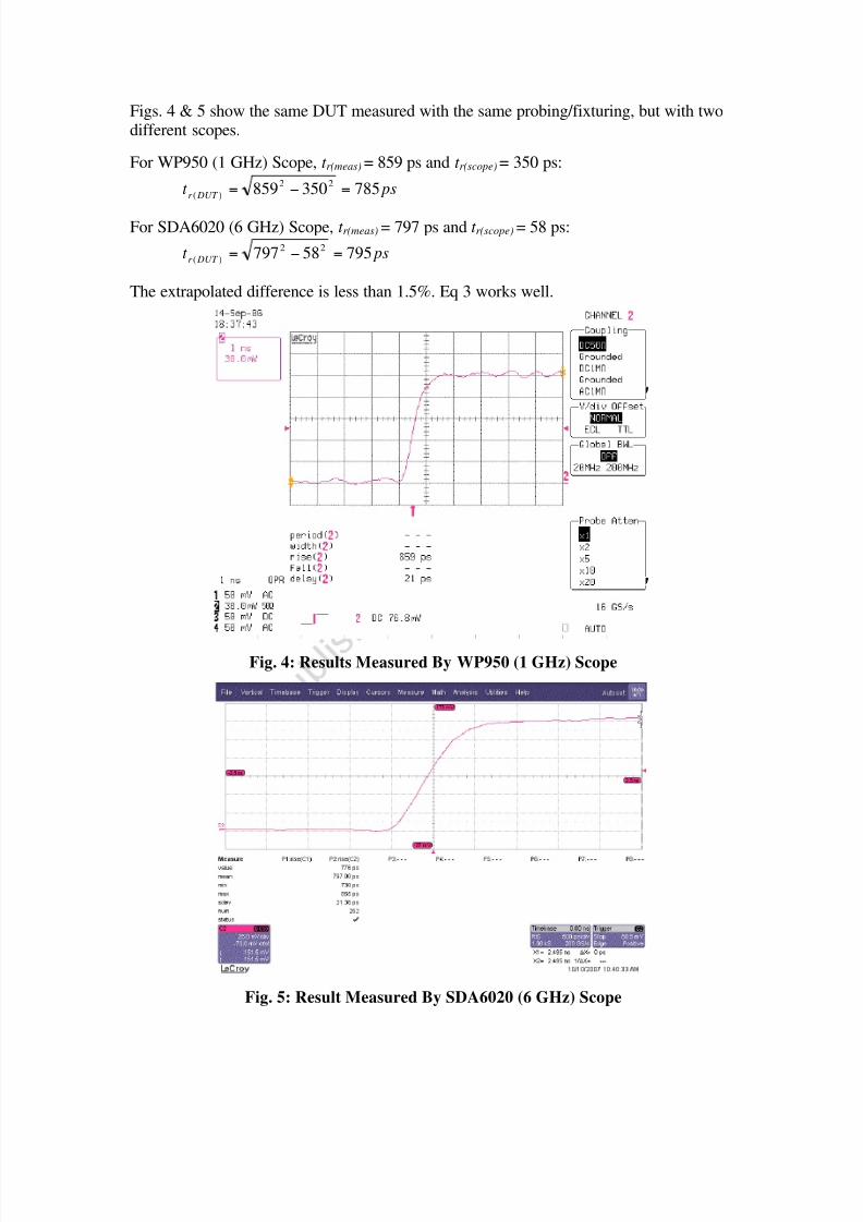
Figs. 4 & 5 show the same DUT measured with the same probing/fixturing, but with twodifferent scopes.
For WP950 (1 GHz) Scope, t r(meas) = 859 ps and t r(scope) = 350 ps:
pst DUT r
78535085922
)(==
For SDA6020 (6 GHz) Scope, t r(meas) = 797 ps and t r(scope) = 58 ps:
pst DUT r 7955879722
)(==
The extrapolated difference is less than 1.5%. Eq 3 works well.
Fig. 4: Results Measured By WP950 (1 GHz) Scope
Fig. 5: Result Measured By SDA6020 (6 GHz) Scope

8/8/2019 Osciloscope Probe
http://slidepdf.com/reader/full/osciloscope-probe 4/8
Probe And Fixturing
The probe is also an important component in the measurement system. The fixturingincludes location to probe and the process. But it is important not to limit the effective
bandwidth. Some common lab probes are listed in the following table. Each of these
different probes is used to measure an ~800 ps tr signal in a real life lab setting to showhow the fixturing limits the bandwidth of the measurement.
Probe Model # Bandwidth(Datasheet)
Rise Timefrom
Bandwidth
InputCapacitance
InputImpedance
MeasuredBandwidth
10x Passive LeCroyPP007-
WS
500 MHz 700 ps 9.5 pF 10 M 166 MHz
1 k Tektronix
P61583 GHz 117 ps 1.5 pF 1 k 630 MHz
Active FET TektronixP6245 1.5 GHz 233 ps <1.0 pF 1 M
580 MHz
Differential TektronixP6247
1 GHz 350 ps <1 pF(differential)
<2 pF(common)
200 k (diff)100 k
(common)
540 MHz
Table 1: Common Lab Probes
The probe bandwidth listed in the datasheet is under an ideal setup. It’s important to
consider the fixturing effect.2
)(
2
)_()_( fixturingr ideal prober effective prober t t t +=
1) First, try the 10x LeCroy PP007-WS with a 1 GHz scope. The 10x probe has a
large parasitic capacitance (9.5 pF) and inductance which is not good for highfrequency measurement. It has a very high input impedance (10 M) and its
low price makes it a common tool in the lab. Shown in Fig. 6, the left pictureis the set up and the right graph is a screen shot on the scope. The 10x probe
with a long ground lead (2 - 3 inches) exhibits lots of inductance. It’s possibleto estimate the effective bandwidth of this setup as following. Then it is clear
that the fixturing decreases the bandwidth from 500MHz to 166MHz.
2
)(
2
)(
35.0
DUT risemeasrise
meas
t t
BW
=
BWmeas1 = 166 MHz

8/8/2019 Osciloscope Probe
http://slidepdf.com/reader/full/osciloscope-probe 5/8
Fig. 6: 10x Probe Test Setting And Result For ~800 ps Rise Time ( t r(meas) = 2242 ps)
Ltip
Ctip
9M
1MDUT
1.5p
Oscilloscope
Z0~100k
LGND
Fig. 7: Block Diagram Of 10x Probe With Oscilloscope
2) Next, a test using the 1 k probe Tektronix P6158 with 6 GHz scope. The 1 k probe is also common in the lab. It shows a smaller parasitic capacitance
(1.5 pF), higher bandwidth (3 GHz), and a modest price. Its input impedance
is only 1 k , which tends to limit its applications. A ground coil is used todecrease the inductance. The estimated effective bandwidth of this setup is630 MHz, which is much smaller than the 3 GHz on the datasheet.
Fig. 8: 1 k Probe Test Setting/Result For ~800 ps rise time ( t r(meas) = 976 ps)

8/8/2019 Osciloscope Probe
http://slidepdf.com/reader/full/osciloscope-probe 6/8
3) Also available is the Active FET Probe Tektronix P6245 with a 4 GHz scope.
The Active FET Probe is much more expensive. It has a high input impedance(1 M) and high bandwidth (1.5 GHz) with small parasitic capacitance
(<1.0 pF). The estimated effective bandwidth of this setup is 580 MHz.
Fig. 9: Active Probe Test Setting/Result For ~800 ps Rise Time ( t r(meas) = 1004 ps)
4) A differential probe (Tektronix P6247) with the 6 GHz scope also can be used.The differential probe has a medium bandwidth (1 GHz), small parasitic
capacitance (<1 pF) and medium input impedance (200 k ). It is good fordifferential applications. The estimated effective bandwidth of this setup is
540 MHz. This is a higher priced alternative.
Fig. 10: Diff Probe Test Setting/Result For ~800 ps Rise Time ( t r(meas) = 1029 ps)
5) The final option is a 1 k built-in probe with 6 GHz scope. This is built on the
evaluation board and used when no high-end probe is available. (Fig 11.) Theprobe directly tests the output pin of the device. Following a 950 resistor, is
a 50 trace to the BNC or SMA connector. Just using the normal BNC orSMA cable to the scope, the scope needs to be set to 50 termination. This
50 load combines with 950 to be a resistor divider. So the output shouldbe 1/20 attenuation. This probe was used to measure t r(meas) = 797 ps, which
represents the best result of all options. And, it can be used as a reference toestimate the performance of other probes.

8/8/2019 Osciloscope Probe
http://slidepdf.com/reader/full/osciloscope-probe 7/8
The advantages of this method include:
• No need to consider GND lead
• 50 trace provides very wide bandwidth
• Consistent measurement – there is no need for ground clips
• It is cheaper to supply coax cable
• Output traces can be of the same length to assure the same delay timebetween two outputs
There are some limitations for this method, including:
• The DUT must drive 1 k load
• Limited 20x gain setting availability in this scope
• The cable length can also affect the performance. A short cable is
preferred
This built-in probe allows the customer to easily use an evaluation board. The customer just needs the right scope (with a decent bandwidth) and a good cable. It is already used
on some evaluation boards of our products, like SERDES.
Fig. 11: 1 k Built-In Probe ( t r(meas ) = 797 ps)
With the requirement to measure the fast rise time, the low frequency signal doesn’t
mean the required system bandwidth is low. Normally, a 1 GHz oscilloscope is enough tomeasure a 1 ns rise time regardless of signal frequency. Ground leads of the probe can
kill the bandwidth. So it is vital to choose the proper bandwidth for the probe and scope.A 1 k built-in probe is a very helpful high bandwidth probe for fast rise time
measurements.

8/8/2019 Osciloscope Probe
http://slidepdf.com/reader/full/osciloscope-probe 8/8
About The Author
Jian Wang was born in China in 1975 and has served as an applications engineer withIntersil since 2005, focusing on high-speed amplifiers and drivers. He earned a PhD from
the University of California at Davis in 2006.