oscilloscope instruction manual - pintek … diagram description features ... equipment limited for...
TRANSCRIPT

20MHz 25MHz
MHz 40MHz
0MHz 60MHz 100MHz
OscilloscopeOscilloscope
30 OscilloscopeOscilloscope
5 OscilloscopeOscilloscope
Oscilloscope
For Series Models:
OSCILLOSCOPE INSTRUCTION MANUAL

Table Of Contents:
Test Instrument Safety
General
Notice Before Operation
Operating Instructions
Application
Maintenance
Block Diagram
DescriptionFeatures
20MHz Specifications
25MHz Specifications
30MHz Specifications
40MHz Specifications
50MHz Specifications
60MHz Specifications
100MHz Specifications
Controls and Indicators
Safety precautionsEquipment protection precautionsOperating tipsInitial starting procedureSingle trace displayDual trace displayTriggeringTime base controlX-Y OperationComponent test
DC Voltage measurementsMeasurement of voltage between two point on a waveformTime measurementsFrequency measurementsPulse width measurementsPulse rise time and fall time measurementsTime difference measurementPhase difference measurementsX-Y Mode applicationsFrequency response measurements
1
3
33
5
23
26
40
28
40
42
42
43
43
45
47
49
49
51
40
8
11
20
51
52
53
54
56
57
58
59
61
62
63
14
17
65

1
Normal use of test equipment exposes you to a certain amount of danger from electrical
shock because testing must often be performed where exposed high voltage is present.
An electrical shock causing 10 milliamps of current to pass through the heart will stop
most human heartbeats. Voltage as low as 35 volts DC or AC rms should be considered
dangerous and hazardous since it can produce a lethal current under certain conditions.
Higher voltage poses an even greater threat because such voltage can more easily
produce a lethal current. Your normal work habits should include all accepted practices
that will prevent contact with exposed high voltage, and that will steer current away
from your heart in case of accidental contact with a high voltage. You will significantly
reduce the risk factor if you know and observe the following safety precautions.
Test Instrument Safety OSCILLOSCOPE INSTRUCTION MANUAL
WARNING
1. Don't expose high voltage needlessly in the equipment under test. Remove
housings and covers only when necessary. Turn off equipment while making test
connections in high-voltage circuits. Discharge high-voltage capacitors after
removing power.
2. If possible, familiarize yourself with the equipment being tested and the
location of its high voltage points. However, remember that high voltage may
appear at unexpected points in defective equipment.
3. Use an insulated floor material or a large, insulated floor mat to stand on, and an
insulated work surface on which to place equipment; make certain such surfaces
are not damp or wet.
4. Use the time-proven "one hand in the pocket" technique while handling an
instrument probe. Be particularly careful to avoid contacting a nearby metal object
that could provide a good ground return path.
5. When using a probe, touch only the insulated portion. Never touch the exposed tip
portion.
6. When testing ac powered equipment, remember that ac line voltage is usually
present on some power input circuits such as the on-off switch, fuses, power
transformer, etc. any time the equipment is connected to an ac outlet, even if
the equipment is turned off.

7. Some equipment with a two-wire ac power cord, including some with polarized
power plugs, is the "hot chassis" type. This includes most recent television receivers
and audio equipment. A plastic or wooden cabinet insulates the chassis to protect
the customer. When the cabinet is removed for servicing, a serious shock hazard
exists if the chassis is touched. Not only does this present a dangerous shock
hazard, but damage to test instruments or the equipment under test may result
from connecting the ground lead of most test instruments (including this
oscilloscope) to a "hot chassis". To make measurements in "hot chassis"
equipment, always connect an isolation transformer between the ac outlet and the
equipment under test. To be on the safe side, treat all two wire ac powered
equipment as "hot chassis" unless you are sure it has an isolated chassis or an earth
ground chassis.
8. Never work alone. Someone should be nearby to render aid if necessary. Training in
CPR (cardio-pulmonary resuscitation) first aid is highly recommended.
9. Equipment limited for use in CS and RS controlled environmental conditions.
2
TEST INSTRUMENT SAFETY

3
General OSCILLOSCOPE INSTRUCTION MANUAL
DESCRIPTION
The model PS-XX0/XX1/XX5 oscilloscope is a dual-channel oscilloscope with frequency bandwidth 20~100 MHz at -3dB; maximum sweep 10 nS/DIV; maximum sensitivity 1 mV/DIV and 150 mm rectangular CRT with internal graticule.
The oscilloscope is rugged, easy to operate and highly reliable. It also provide many convenient feature and special functions which make itself be an special for research, production , education, and development in electronic device or circuitry.
FEATURES
(1) Ease of Operation
All control and function switches are laid out in the most convenient locations making the oscilloscope extremely easy to operate.
(2) High Input Impedance
The input impedance of CH 1, CH 2 IS 1MΩ ±2%, 25 pF ±10pF.
(3) Variable Hold Off Function
Signals with complex repeating periods which resist triggering can be stably triggered with a simple adjustment of the hold off level.
(4) X-Y Operation
CH 1 can be applied as horizontal deflection (X-axis) while CH 2 provides vertical deflection (Y-axis).
(5) Trigger l of TV Sync
The oscilloscope has a sync separator circuit, which allows triggering for TV-H and TV-V signal.
(6) High Sensitivity
1 mV/DIV maximum vertical sensitivity. 10 nS/DIV maximum sweep rate.
(7) Sweep Mix Function (XX5 only)
The main sweep and the delay sweep can be viewed at the same time.
(8) CH 2 Output (XX5 only)
CH 2 output which on near panel can be connected to frequency counters and other modulation signal.
4
GENERAL
(9) Z Modulation (XX5 only)
Input terminal is used for external intensity modulation signal.
(10) Component Test (XX1/XX5)
Capacitor, indicator, diode, transistor and zener can be also viewed on screen.
(11) Beam Finder (XX1/XX5)
Trace can be returned to CRT viewing area regardless of setting horizontal, vertical or intensity controls when press beam finder button.
(12) Illumination Control (XX1/XX5)
Graticule illumination can be adjusted according to brightness of circumstance.

5
20MHz Specifications
CATHODE RAY TUBE
VERTICAL DEFLECTION
Bandwidth: DC~20 MHz(-3dB)
Sensitivity:
1mV/DIV~1V/DIV(5MHz, -3dB), x5 gain selected.
5mV/DIV~5V/DIV
Attenuator: 1-2-5 sequence, 10 step with variable control.
:
:
:
HORIZONTAL DEFLECTION
°
6 inch diagonal, rectangular screen with internal graticule 8 x 10 DIV
(1 DIV=1cm), P31 phosphor, 2kV accel voltage.
Input Impedance 1MΩ±2%, 25pF±10%
Max. Input Voltage 400V (DC+AC peak)
Rise Time About 17.5nS
Over Shoot: ≦3%
Operation Mode: CH1, CH2, DUAL(ALT,CHOP)
Algebraic Addition: CH1+CH2, CH1-CH2
Inverter: CH2 only
X-Y Mode: Switch selectable using X-Y switch
CH 1= X axis. CH 2: Y axis.
Accuracy: Y-Axis ±3% ; X-Axis ±6%
Bandwidth: DC-1MHz(-3dB)
X-Y Phase Difference: <3 (50KHz)
SWEEP SYSTEM
Sweep Display Mode: Main, Mix, Delay(XX5 only)
Hold Off Time: 5:1 continuously variable.
OSCILLOSCOPE INSTRUCTION MANUAL
6
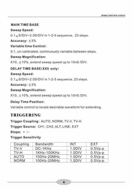
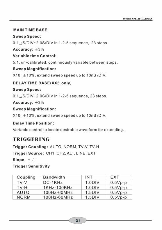
MAIN TIME BASE
Sweep Speed:
0.1μS/DIV~2.0S/DIV in 1-2-5 sequence, 23 steps.
Accuracy: ±3%
±
Sweep Speed:
0.1μS/DIV~2.0S/DIV in 1-2-5 sequence, 23 steps.
Accuracy: ±3%
±
TRIGGERING
Trigger Coupling: AUTO, NORM, TV-V, TV-H
Trigger Source: CH1, CH2, ALT, LINE, EXT
Slope: + / -
Trigger Sensitivity
Variable time Control:
5:1, un-calibrated, continuously variable between steps.
Sweep Magnification:
X10, 10%, extend sweep speed up to 10nS /DIV.
DELAY TIME BASE(XX5 only)
Sweep Magnification:
X10, 10%, extend sweep speed up to 10nS /DIV.
Delay Time Position:
Variable control to locate desirable waveform for extending.
Coupling Bandwidth INT EXTTV-V DC-1KHz 1.0DIV 0.5Vp-pTV-H 1KHz-100KHz 1.0DIV 0.5Vp-pAUTO 100Hz-20MHz 1.5DIV 0.5Vp-pNORM 100Hz-20MHz 1.5DIV 0.5Vp-p
20MHZ SPECIFICATIONS
7
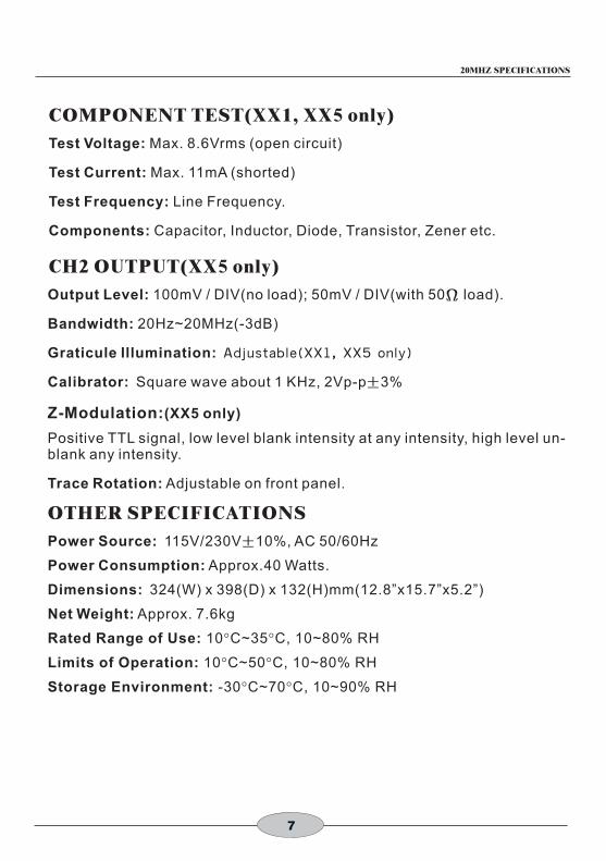
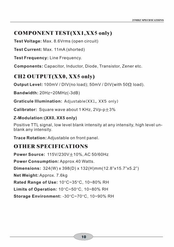
COMPONENT TEST(XX1, XX5 only)
Test Voltage: Max. 8.6Vrms (open circuit)
Test Current: Max. 11mA (shorted)
Test Frequency: Line Frequency.
Components: Capacitor, Inductor, Diode, Transistor, Zener etc.
CH2 OUTPUT(XX5 only)
Output Level: 100mV / DIV(no load); 50mV / DIV(with 50Ω load).
Bandwidth: 20Hz~20MHz(-3dB)
Calibrator: Square wave about 1 KHz, 2Vp-p±3%
OTHER SPECIFICATIONS
Power Source: 115V/230V±10%, AC 50/60Hz
Power Consumption: Approx.40 Watts.
Dimensions: 324(W) x 398(D) x 132(H)mm(12.8”x15.7”x5.2”)
Net Weight: Approx. 7.6kg
Rated Range of Use: 10 C~35 C, 10~80% RH
Limits of Operation: 10 C~50 C, 10~80% RH
Storage Environment: -30 C~70 C, 10~90% RH
Graticule Illumination: Adjustab le(XX1, XX5 on ly)
Z-Modulation:(XX5 only)
Positive TTL signal, low level blank intensity at any intensity, high level un-blank any intensity.
Trace Rotation: Adjustable on front panel.
° °
° °
° °
20MHZ SPECIFICATIONS

8
25MHz Specifications
CATHODE RAY TUBE
VERTICAL DEFLECTION
Bandwidth: DC~25 MHz(-3dB)
Sensitivity:
1mV/DIV~1V/DIV(10MHz, -3dB), x5 gain selected.
5mV/DIV~5V/DIV
Attenuator: 1-2-5 sequence, 10 step with variable control.
:
:
:
HORIZONTAL DEFLECTION
°
6 inch diagonal, rectangular screen with internal graticule 8 x 10 DIV
(1 DIV=1cm), P31 phosphor , 2kV accel voltage.
Input Impedance 1MΩ±2%, 25pF±10%
Max. Input Voltage 400V (DC+AC peak)
Rise Time About 14nS
Over Shoot: ≦5%
Operation Mode: CH1, CH2, DUAL(ALT,CHOP)
Algebraic Addition: CH1+CH2, CH1-CH2
Inverter: CH2 only
X-Y Mode: Switch selectable using X-Y switch
CH 1= X axis. CH 2: Y axis.
Accuracy: Y-Axis ±3% ; X-Axis ±6%
Bandwidth: DC-1MHz(-3dB)
X-Y Phase Difference: <3 (50KHz)
SWEEP SYSTEM
Sweep Display Mode: Main, Mix, Delay(XX5 only)
Hold Off Time: 5:1 continuously variable.
OSCILLOSCOPE INSTRUCTION MANUAL

9
MAIN TIME BASE
Sweep Speed:
0.1μS/DIV~2.0S/DIV in 1-2-5 sequence, 23 steps.
Accuracy: ±3%
±
Sweep Speed:
0.1μS/DIV~2.0S/DIV in 1-2-5 sequence, 23 steps.
Accuracy: ±3%
±
TRIGGERING
Trigger Coupling: AUTO, NORM, TV-V, TV-H
Trigger Source: CH1, CH2, ALT, LINE, EXT
Slope: + / -
Trigger Sensitivity
Variable time Control:
5:1, un-calibrated, continuously variable between steps.
Sweep Magnification:
X10, 10%, extend sweep speed up to 10nS /DIV.
DELAY TIME BASE(XX5 only)
Sweep Magnification:
X10, 10%, extend sweep speed up to 10nS /DIV.
Delay Time Position:
Variable control to locate desirable waveform for extending.
Coupling Bandwidth INT EXTTV-V DC-1KHz 1.0DIV 0.5Vp-pTV-H 1KHz-100KHz 1.0DIV 0.5Vp-pAUTO 100Hz-25MHz 1.5DIV 0.5Vp-pNORM 100Hz-25MHz 1.5DIV 0.5Vp-p
25MHZ SPECIFICATIONS
COMPONENT TEST(XX1,XX5 only)
Test Voltage: Max. 8.6Vrms (open circuit)
Test Current: Max. 11mA (shorted)
Test Frequency: Line Frequency.
Components: Capacitor, Inductor, Diode, Transistor, Zener etc.
CH2 OUTPUT(XX0, XX5 only)
Output Level: 100mV / DIV(no load); 50mV / DIV(with 50Ω load).
Bandwidth: 20Hz~20MHz(-3dB)
Calibrator: Square wave about 1 KHz, 2Vp-p±3%
OTHER SPECIFICATIONS
Power Source: 115V/230V±10%, AC 50/60Hz
Power Consumption: Approx.40 Watts.
Dimensions: 324(W) x 398(D) x 132(H)mm(12.8”x15.7”x5.2”)
Net Weight: Approx. 7.6kg
Rated Range of Use: 10 C~35 C, 10~80% RH
Limits of Operation: 10 C~50 C, 10~80% RH
Storage Environment: -30 C~70 C, 10~90% RH
Graticule Illumination: Adjustab le(XX1, XX5 on ly)
Z-Modulation:(XX0, XX5 only)
Positive TTL signal, low level blank intensity at any intensity, high level un-blank any intensity.
Trace Rotation: Adjustable on front panel.
° °
° °
° °
10
25MHZ SPECIFICATIONS

30MHz Specifications
CATHODE RAY TUBE
VERTICAL DEFLECTION
Bandwidth: DC~30 MHz(-3dB)
Sensitivity:
1mV/DIV~1V/DIV(10MHz, -3dB), x5 gain selected.
5mV/DIV~5V/DIV
Attenuator: 1-2-5 sequence, 10 step with variable control.
:
:
:
HORIZONTAL DEFLECTION
°
6 inch diagonal, rectangular screen with internal graticule 8 x 10 DIV
(1 DIV=1cm), P31 phosphor.
Input Impedance 1MΩ±2%, 25pF±10%
Max. Input Voltage 400V (DC+AC peak)
Rise Time About 12nS; 35 nS at X5 MAG.
Over Shoot: ≦5%
Operation Mode: CH1, CH2, DUAL(ALT,CHOP)
Algebraic Addition: CH1+CH2, CH1-CH2
Inverter: CH2 only
X-Y Mode: Switch selectable using X-Y switch
CH 1= X axis. CH 2: Y axis.
Accuracy: Y-Axis ±3% ; X-Axis ±6%
Bandwidth: DC-1MHz(-3dB)
X-Y Phase Difference: <3 (50KHz)
SWEEP SYSTEM
Sweep Display Mode: Main, Mix, Delay(XX5 only)
Hold Off Time: 5:1 continuously variable.
OSCILLOSCOPE INSTRUCTION MANUAL
11

MAIN TIME BASE
Sweep Speed:
0.1μS/DIV~2.0S/DIV in 1-2-5 sequence, 23 steps.
Accuracy: ±3%
±
Sweep Speed:
0.1μS/DIV~2.0S/DIV in 1-2-5 sequence, 23 steps.
Accuracy: ±3%
±
TRIGGERING
Trigger Coupling: AUTO, NORM, TV-V, TV-H
Trigger Source: CH1, CH2, ALT, LINE, EXT
Slope: + / -
Trigger Sensitivity
Variable time Control:
5:1, un-calibrated, continuously variable between steps.
Sweep Magnification:
X10, 10%, extend sweep speed up to 10nS /DIV.
DELAY TIME BASE(XX5 only)
Sweep Magnification:
X10, 10%, extend sweep speed up to 10nS /DIV.
Delay Time Position:
Variable control to locate desirable waveform for extending.
Coupling Bandwidth INT EXTTV-V DC-1KHz 1.0DIV 0.5Vp-pTV-H 1KHz-100KHz 1.0DIV 0.5Vp-pAUTO 100Hz-30MHz 1.5DIV 0.5Vp-pNORM 100Hz-30MHz 1.5DIV 0.5Vp-p
30MHZ SPECIFICATIONS
12

COMPONENT TEST(XX5 only)
Test Voltage: Max. 8.6Vrms (open circuit)
Test Current: Max. 11mA (shorted)
Test Frequency: Line Frequency.
Components: Capacitor, Inductor, Diode, Transistor, Zener etc.
CH2 OUTPUT(XX5 only)
Output Level: 100mV / DIV(no load); 50mV / DIV(with 50Ω load).
Bandwidth: 20Hz~20MHz(-3dB)
Calibrator: Square wave about 1 KHz, 2Vp-p±3%
OTHER SPECIFICATIONS
Power Source: 115V/230V±10%, AC 50/60Hz
Power Consumption: Approx.40 Watts.
Dimensions: 324(W) x 398(D) x 132(H)mm(12.8”x15.7”x5.2”)
Net Weight: Approx. 7.6kg
Rated Range of Use: 10 C~35 C, 10~80% RH
Limits of Operation: 10 C~50 C, 10~80% RH
Storage Environment: -30 C~70 C, 10~90% RH
Graticule Illumination: Adjustab le(XX5 on ly)
Z-Modulation:(XX5 only)
Positive TTL signal, low level blank intensity at any intensity, high level un-blank any intensity.
Trace Rotation: Adjustable on front panel.
° °
° °
° °
13
30MHZ SPECIFICATIONS

40MHz Specifications
CATHODE RAY TUBE
VERTICAL DEFLECTION
Bandwidth: DC~40 MHz(-3dB)
Sensitivity:
1mV/DIV~1V/DIV(10MHz, -3dB), x5 gain selected.
5mV/DIV~5V/DIV
Attenuator: 1-2-5 sequence, 10 step with variable control.
:
:
:
HORIZONTAL DEFLECTION
°
6 inch diagonal, rectangular screen with internal graticule 8 x 10 DIV
(1 DIV=1cm), P31 phosphor.
Input Impedance 1MΩ±2%, 25pF±10%
Max. Input Voltage 400V (DC+AC peak)
Rise Time About 8.8nS
Over Shoot: ≦5%
Operation Mode: CH1, CH2, DUAL(ALT,CHOP)
Algebraic Addition: CH1+CH2, CH1-CH2
Inverter: CH2 only
X-Y Mode: Switch selectable using X-Y switch
CH 1= X axis. CH 2: Y axis.
Accuracy: Y-Axis ±3% ; X-Axis ±6%
Bandwidth: DC-1MHz(-3dB)
X-Y Phase Difference: <3 (50KHz)
SWEEP SYSTEM
Sweep Display Mode: Main, Mix, Delay(XX5 only)
Hold Off Time: 5:1 continuously variable.
OSCILLOSCOPE INSTRUCTION MANUAL
14

MAIN TIME BASE
Sweep Speed:
0.1μS/DIV~2.0S/DIV in 1-2-5 sequence, 23 steps.
Accuracy: ±3%
±
Sweep Speed:
0.1μS/DIV~2.0S/DIV in 1-2-5 sequence, 23 steps.
Accuracy: ±3%
±
TRIGGERING
Trigger Coupling: AUTO, NORM, TV-V, TV-H
Trigger Source: CH1, CH2, ALT, LINE, EXT
Slope: + / -
Trigger Sensitivity
Variable time Control:
5:1, un-calibrated, continuously variable between steps.
Sweep Magnification:
X10, 10%, extend sweep speed up to 10nS /DIV.
DELAY TIME BASE(XX5 only)
Sweep Magnification:
X10, 10%, extend sweep speed up to 10nS /DIV.
Delay Time Position:
Variable control to locate desirable waveform for extending.
Coupling Bandwidth INT EXTTV-V DC-1KHz 1.0DIV 0.5Vp-pTV-H 1KHz-100KHz 1.0DIV 0.5Vp-pAUTO 100Hz-40MHz 1.5DIV 0.5Vp-pNORM 100Hz-40MHz 1.5DIV 0.5Vp-p
15
40MHZ SPECIFICATIONS

COMPONENT TEST( XX1, XX5 only)
Test Voltage: Max. 8.6Vrms (open circuit)
Test Current: Max. 11mA (shorted)
Test Frequency: Line Frequency.
Components: Capacitor, Inductor, Diode, Transistor, Zener etc.
CH2 OUTPUT(XX5 only)
Output Level: 100mV / DIV(no load); 50mV / DIV(with 50Ω load).
Bandwidth: 20Hz~20MHz(-3dB)
Calibrator: Square wave about 1 KHz, 2Vp-p±3%
OTHER SPECIFICATIONS
Power Source: 115V/230V±10%, AC 50/60Hz
Power Consumption: Approx.40 Watts.
Dimensions: 324(W) x 398(D) x 132(H)mm(12.8”x15.7”x5.2”)
Net Weight: Approx. 7.6kg
Rated Range of Use: 10 C~35 C, 10~80% RH
Limits of Operation: 10 C~50 C, 10~80% RH
Storage Environment: -30 C~70 C, 10~90% RH
Graticule Illumination: Adjustab le(XX1, XX5 on ly)
Z-Modulation:(XX5 only)
Positive TTL signal, low level blank intensity at any intensity, high level un-blank any intensity.
Trace Rotation: Adjustable on front panel.
° °
° °
° °
16
40MHZ SPECIFICATIONS
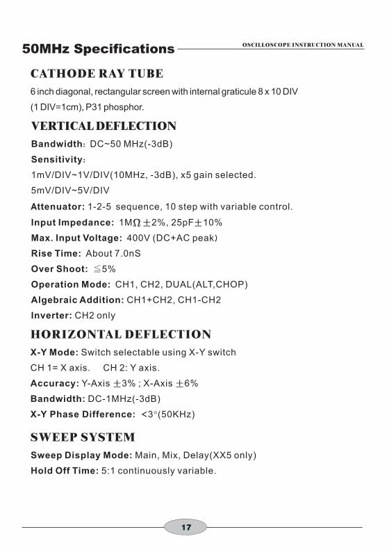
50MHz Specifications
CATHODE RAY TUBE
VERTICAL DEFLECTION
Bandwidth: DC~50 MHz(-3dB)
Sensitivity:
1mV/DIV~1V/DIV(10MHz, -3dB), x5 gain selected.
5mV/DIV~5V/DIV
Attenuator: 1-2-5 sequence, 10 step with variable control.
:
:
:
HORIZONTAL DEFLECTION
°
6 inch diagonal, rectangular screen with internal graticule 8 x 10 DIV
(1 DIV=1cm), P31 phosphor.
Input Impedance 1MΩ±2%, 25pF±10%
Max. Input Voltage 400V (DC+AC peak)
Rise Time About 7.0nS
Over Shoot: ≦5%
Operation Mode: CH1, CH2, DUAL(ALT,CHOP)
Algebraic Addition: CH1+CH2, CH1-CH2
Inverter: CH2 only
X-Y Mode: Switch selectable using X-Y switch
CH 1= X axis. CH 2: Y axis.
Accuracy: Y-Axis ±3% ; X-Axis ±6%
Bandwidth: DC-1MHz(-3dB)
X-Y Phase Difference: <3 (50KHz)
SWEEP SYSTEM
Sweep Display Mode: Main, Mix, Delay(XX5 only)
Hold Off Time: 5:1 continuously variable.
OSCILLOSCOPE INSTRUCTION MANUAL
17

MAIN TIME BASE
Sweep Speed:
0.1μS/DIV~2.0S/DIV in 1-2-5 sequence, 23 steps.
Accuracy: ±3%
±
Sweep Speed:
0.1μS/DIV~2.0S/DIV in 1-2-5 sequence, 23 steps.
Accuracy: ±3%
±
TRIGGERING
Trigger Coupling: AUTO, NORM, TV-V, TV-H
Trigger Source: CH1, CH2, ALT, LINE, EXT
Slope: + / -
Trigger Sensitivity
Variable time Control:
5:1, un-calibrated, continuously variable between steps.
Sweep Magnification:
X10, 10%, extend sweep speed up to 10nS /DIV.
DELAY TIME BASE(XX5 only)
Sweep Magnification:
X10, 10%, extend sweep speed up to 10nS /DIV.
Delay Time Position:
Variable control to locate desirable waveform for extending.
Coupling Bandwidth INT EXTTV-V DC-1KHz 1.0DIV 0.5Vp-pTV-H 1KHz-100KHz 1.0DIV 0.5Vp-pAUTO 100Hz-40MHz 1.5DIV 0.5Vp-pNORM 100Hz-40MHz 1.5DIV 0.5Vp-p
18
50MHZ SPECIFICATIONS

COMPONENT TEST( XX1, XX5 only)
Test Voltage: Max. 8.6Vrms (open circuit)
Test Current: Max. 11mA (shorted)
Test Frequency: Line Frequency.
Components: Capacitor, Inductor, Diode, Transistor, Zener etc.
CH2 OUTPUT(XX5 only)
Output Level: 100mV / DIV(no load); 50mV / DIV(with 50Ω load).
Bandwidth: 20Hz~20MHz(-3dB)
Calibrator: Square wave about 1 KHz, 2Vp-p±3%
OTHER SPECIFICATIONS
Power Source: 115V/230V±10%, AC 50/60Hz
Power Consumption: Approx.40 Watts.
Dimensions: 324(W) x 398(D) x 132(H)mm(12.8”x15.7”x5.2”)
Net Weight: Approx. 7.6kg
Rated Range of Use: 10 C~35 C, 10~80% RH
Limits of Operation: 10 C~50 C, 10~80% RH
Storage Environment: -30 C~70 C, 10~90% RH
Graticule Illumination: Adjustab le(XX1, XX5 on ly)
Z-Modulation:(XX5 only)
Positive TTL signal, low level blank intensity at any intensity, high level un-blank any intensity.
Trace Rotation: Adjustable on front panel.
° °
° °
° °
19
50MHZ SPECIFICATIONS

60MHz Specifications
CATHODE RAY TUBE
VERTICAL DEFLECTION
Bandwidth: DC~60 MHz(-3dB)
Sensitivity:
1mV/DIV~1V/DIV(10MHz, -3dB), x5 gain selected.
5mV/DIV~5V/DIV
Attenuator: 1-2-5 sequence, 10 step with variable control.
:
:
:
HORIZONTAL DEFLECTION
°
6 inch diagonal, rectangular screen with internal graticule 8 x 10 DIV
(1 DIV=1cm), P31 phosphor, 12kV accel voltage.
Input Impedance 1MΩ±2%, 25pF±10%
Max. Input Voltage 400V (DC+AC peak)
Rise Time About 5.8nS
Over Shoot: ≦5%
Operation Mode: CH1, CH2, DUAL(ALT,CHOP)
Algebraic Addition: CH1+CH2, CH1-CH2
Inverter: CH2 only
X-Y Mode: Switch selectable using X-Y switch
CH 1= X axis. CH 2: Y axis.
Accuracy: Y-Axis ±3% ; X-Axis ±6%
Bandwidth: DC-1MHz(-3dB)
X-Y Phase Difference: <3 (50KHz)
SWEEP SYSTEM
Sweep Display Mode: Main, Mix, Delay(XX5 only)
Hold Off Time: 5:1 continuously variable.
20
60MHZ SPECIFICATIONS
MAIN TIME BASE
Sweep Speed:
0.1μS/DIV~2.0S/DIV in 1-2-5 sequence, 23 steps.
Accuracy: ±3%
±
Sweep Speed:
0.1μS/DIV~2.0S/DIV in 1-2-5 sequence, 23 steps.
Accuracy: ±3%
±
TRIGGERING
Trigger Coupling: AUTO, NORM, TV-V, TV-H
Trigger Source: CH1, CH2, ALT, LINE, EXT
Slope: + / -
Trigger Sensitivity
Variable time Control:
5:1, un-calibrated, continuously variable between steps.
Sweep Magnification:
X10, 10%, extend sweep speed up to 10nS /DIV.
DELAY TIME BASE(XX5 only)
Sweep Magnification:
X10, 10%, extend sweep speed up to 10nS /DIV.
Delay Time Position:
Variable control to locate desirable waveform for extending.
Coupling Bandwidth INT EXTTV-V DC-1KHz 1.0DIV 0.5Vp-pTV-H 1KHz-100KHz 1.0DIV 0.5Vp-pAUTO 100Hz-60MHz 1.5DIV 0.5Vp-pNORM 100Hz-60MHz 1.5DIV 0.5Vp-p
21
60MHZ SPECIFICATIONS

COMPONENT TEST( XX1, XX5 only)
Test Voltage: Max. 8.6Vrms (open circuit)
Test Current: Max. 11mA (shorted)
Test Frequency: Line Frequency.
Components: Capacitor, Inductor, Diode, Transistor, Zener etc.
CH2 OUTPUT(XX5 only)
Output Level: 100mV / DIV(no load); 50mV / DIV(with 50Ω load).
Bandwidth: 20Hz~20MHz(-3dB)
Calibrator: Square wave about 1 KHz, 2Vp-p±3%
OTHER SPECIFICATIONS
Power Source: 115V/230V±10%, AC 50/60Hz
Power Consumption: Approx.45 Watts.
Dimensions: 324(W) x 398(D) x 132(H)mm(12.8”x15.7”x5.2”)
Net Weight: Approx. 7.6kg
Rated Range of Use: 10 C~35 C, 10~80% RH
Limits of Operation: 10 C~50 C, 10~80% RH
Storage Environment: -30 C~70 C, 10~90% RH
Graticule Illumination: Adjustab le(XX1, XX5 on ly)
Z-Modulation:(XX5 only)
Positive TTL signal, low level blank intensity at any intensity, high level un-blank any intensity.
Trace Rotation: Adjustable on front panel.
° °
° °
° °
22
60MHZ SPECIFICATIONS

100MHz Specifications
CATHODE RAY TUBE
VERTICAL DEFLECTION
Bandwidth: DC~100 MHz(-3dB)
Sensitivity:
1mV/DIV~1V/DIV(20MHz, -3dB), x5 gain selected.
5mV/DIV~5V/DIV
Attenuator: 1-2-5 sequence, 10 step with variable control.
:
:
:
HORIZONTAL DEFLECTION
°
6 inch diagonal, rectangular screen with internal graticule 8 x 10 DIV
(1 DIV=1cm), P31 phosphor, 14kV accel voltage.
Input Impedance 1MΩ±2%, 25pF±10%
Max. Input Voltage 400V (DC+AC peak)
Rise Time ≦ 3.5nS(1mV/DIV=14nS)
Over Shoot: ≦5%
Operation Mode: CH1, CH2, DUAL(ALT,CHOP)
Algebraic Addition: CH1+CH2, CH1-CH2
Inverter: CH2 only
X-Y Mode: Switch selectable using X-Y switch
CH 1= X axis. CH 2: Y axis.
Accuracy: Y-Axis ±3% ; X-Axis ±6%
Bandwidth: DC-1MHz(-3dB)
X-Y Phase Difference: <3 (50KHz)
SWEEP SYSTEM
Sweep Display Mode: Main, Mix, Delay(XX5 only)
Hold Off Time: 5:1 continuously variable.
OSCILLOSCOPE INSTRUCTION MANUAL
23

MAIN TIME BASE
Sweep Speed:
0.1μS/DIV~2.0S/DIV in 1-2-5 sequence, 23 steps.
Accuracy: ±3%
±
Sweep Speed:
20nS/DIV~2.0S/DIV in 1-2-5 sequence, 23 steps.
Accuracy: ±3%
±
TRIGGERING
Trigger Coupling: AUTO, NORM, TV-V, TV-H
Trigger Source: CH1, CH2, ALT, LINE, EXT
Slope: + / -
Trigger Sensitivity
Variable time Control:
5:1, un-calibrated, continuously variable between steps.
Sweep Magnification:
X10, 10%, extend sweep speed up to 10nS /DIV.
DELAY TIME BASE(XX5 only)
Sweep Magnification:
X10, 10%, extend sweep speed up to 10nS /DIV.
Delay Time Position:
Variable control to locate desirable waveform for extending.
Coupling Bandwidth INT EXTTV-V DC-1KHz 1.0DIV 0.5Vp-pTV-H 1KHz-100KHz 1.0DIV 0.5Vp-pAUTO 100Hz-100MHz 1.5DIV 0.5Vp-pNORM 100Hz-100MHz 1.5DIV 0.5Vp-p
24
100MHZ SPECIFICATIONS

COMPONENT TEST( XX1, XX5 only)
Test Voltage: Max. 8.6Vrms (open circuit)
Test Current: Max. 11mA (shorted)
Test Frequency: Line Frequency.
Components: Capacitor, Inductor, Diode, Transistor, Zener etc.
CH2 OUTPUT(XX5 only)
Output Level: 100mV / DIV(no load); 50mV / DIV(with 50Ω load).
Bandwidth: 20Hz~20MHz(-3dB)
Calibrator: Square wave about 1 KHz, 2Vp-p±3%
OTHER SPECIFICATIONS
Power Source: 115V/230V±10%, AC 50/60Hz
Power Consumption: Approx.50 Watts.
Dimensions: 324(W) x 398(D) x 132(H)mm(12.8”x15.7”x5.2”)
Net Weight: Approx. 7.6kg
Rated Range of Use: 10 C~35 C, 10~80% RH
Limits of Operation: 10 C~50 C, 10~80% RH
Storage Environment: -30 C~70 C, 10~90% RH
Graticule Illumination: Adjustab le(XX1, XX5 on ly)
Z-Modulation:(XX5 only)
Positive TTL signal, low level blank intensity at any intensity, high level un-blank any intensity.
Trace Rotation: Adjustable on front panel.
° °
° °
° °
25
100MHZ SPECIFICATIONS

1. Unpack the oscilloscope:
After receipt of the instrument, immediately unpack and inspect it for any shipping
damage or missing accessories.
If any sign of damage or missing accessories are found, immediately notify the
dealer.
2. Environmental:
The instrument is designed for "Indoor Use" only. Normally, operational
temperature of the instrument is 5 C to 40 C, and the maximum relative humidity
80% for temperatures up to 31 C, decreasing linearly to 50% relative humidity at
40 C. Operation outside of this temperature range may cause damage to the
circuits.
Do not use the instrument in a place where strong magnetic or electric fields exist.
Such fields may adversely effect your measurement.
3. Check the Line Voltage:
The instrument can operate on any one of the line voltages shown in the below
table by inserting the line voltage selector plug in the corresponding position on
the rear panel.
Before connection the power plug to an AC line outlet, be sure to check that the
voltage selector plug is set in the position corresponding to the desired line
voltage.
° °
°
°
!
SELECTOR LINE VOLTAGE FUSE
115V 100~130V 50/60Hz 800mA
230V 200~260V 50/60Hz 600mA
Line Voltage Range: 100~130VFuse: 800mASelectoe: 115V
Line Voltage Range: 200~260VFuse: 600mASelectoe: 230V
Fig 1. Fig 2.
230V(220/240)
115V(110/125)
230V(220/240)
115V(110/125)
Notice Before Operation OSCILLOSCOPE INSTRUCTION MANUAL
The instrument may not operate properly or may be damaged if it is connected to a wrong AC line voltage. Whenever line voltages are changed, fuses must also be replaced.
CAUTION!
26
POLLUTION DEGREE 2.
This equipment has been evaluated to INSTALLATION CATEGORY (OVERVOLTAGE CATEGORY) II.

OSCILLOSCOPE INSTRUCTION MANUAL
4. Suggestions for successful instrument operation:
Never place heavy objects on the instrument.
Never place a hot soldering iron on or near the instrument.
Never insert wires, pins, or other metal objects into the ventilation fan.
Never move or pull the instrument with the power cord or a probe cord.
Never move instrument when the power cord or a signal probe is connected to
a circuit.
If the instrument is used in a manner not specified by the manufacturer then
protection mechanisms built into the instrument may not function properly.
27

28
32
31
30
29
28
27
26
32
25
24
23
22
21
19
18 1
51
61
41
31
011
97
85
24
1
20
~6
0M
Hz
Sta
nd
ard
Typ
e F
ron
t P
an
el
Controls and Indicators OSCILLOSCOPE INSTRUCTION MANUAL

29
CONTROLS AND INDICATORS
32
31
30
29
28
27
26
32
25
24
23
22
21
19
18 1
61
51
41
31
011
97
65
24
13
81
2
17
20
20
~6
0M
Hz
De
lay
Typ
e F
ron
t P
an
el

30
32
31
30
29
28
27
26
32
25
24
23
22
21
19
18 1
51
61
41
31
011
93
38
52
41
7
10
0M
Hz
Sta
nd
ard
Typ
e F
ron
t P
an
el
CONTROLS AND INDICATORS

31
32
31
30
29
28
27
26
32
25
24
23
22
21
19
18 1
61
51
41
31
011
93
38
52
41
7
17
10
0M
Hz
De
lay
Typ
e F
ron
t P
an
el
CONTROLS AND INDICATORS

32
37
36
35
40
Sta
nd
ard T
ype Rear
Pa
ne
l CONTROLS AND INDICATORS
33
37
36
35
38
39
40
Delay Type Rear
Pa
ne
l CONTROLS AND INDICATORS

34
!
0
1
1. Symbol Indicators:
2. Operating Controls, Indicators and Signal input connectors:
(P.25~30)
GENERAL FUNCTION CONTROLS
ON Indicator(32): Lights when oscilloscope is “on”.
POWER Pushbutton(30): Turns oscilloscope “on” and “off”.
INTENSITY Control(31): Adjusts to maintain trace at a horizontal position.
TRACE ROTATION Control(29): Adjusts to maintain trace at a horizontal position.
FOCUS Control(28): Adjusts trace focus.
20 MHz/100 MHz Pushbutton(33): When released, selects 100MHz bandwidth. When engaged, limits bandwidth to 20 MHz.
COMPONENT TEST Pushbutton(3): With pushbutton set to “in” position, Component Test mode is enabled. Normal scope operation is enabled with pushbutton in “out” position.
COMPONENT TEST Jack(6): “Banana”-type HI-side input jack for connection to component in Component Test operation mode.
GND Terminal(8): Oscilloscope chassis ground jack, and earth ground via three-wire ac power cord.
C
Power OFF
Power ON
Vertical Up
Vertical Down
Horizontal Left
Horizontal Right
Earth Ground
Warning! Risk of Danger
VR With Switch
Conforms to IEC 1010. EN 61010
Complies With U.S. & Canadian Standard
In Spected & Incensed by TUV Product Servies
CONTROLS AND INDICATORS
..

35
CONTROLS AND INDICATORS
CAL Terminal(9): Terminal provides 2V p-p, 1 KHz(nominal) square wave signal. This signal is useful for checking probe compensation adjustment, as well as providing a rough check of vertical calibration.
BEAN FIND Pushbutton(12): Momentary-contact pushbutton speeds setup of trace position by bringing the beam into graticule area; operates independently of other display controls.
VERTICAL CONTROLS
VERTICAL Mode Switch(7)
Selects vertical display mode. Four-position lever switch with the following positions:
CH 1: Displays the channel 1 signal by itself.
CH 2/X-Y:
CH 2: Displays the channel 2 signal by itself.
X-Y: Used in conjunction with the X-Y control and TRIGGER SOURCE switch to enable X-Y display mode.
DUAL:
Displays the channel 1 and channel 2 signals simultaneously, Dual-trace mode may be either alternate or chopped sweep; see the description under HOLD OFF/PULL CHOP ( 100MHz: Cannel 1 POS/PULL CHOP control ).
ADD: The inputs from channel 1 and channel 2 are summed and displayed as a single signal. If the Channel 2 POSITION/PULL INVERT control is pulled out, the input from channel 2 is subtracted from channel 1 and the difference is displayed as a single signal.
CH 1 AC-GND-DC Switch(1)
Three-position lever switch the following positions:
AC: Channel 1 input signal is capacitively coupled; dc component is blocked.
GND: Opens signal path and grounds input to vertical amplifier. This provides a zero-volt base line, the position of which can be used as a reference when performing dc measurements.
DC: Direct coupling of channel 1 input signal; both ac and dc components of signal produce vertical deflection.
CH 1(X) Input Jack(2): Vertical input for channel 1, X-axis input for X-Y operation.

36
CONTROLS AND INDICATORS
CH 1 (X) VOLTS/DIV Control(4):
Vertical attenuator for channel 1. Provides step adjustment of vertical sensitivity. When channel 1 VARIABLE control is set to CAL, vertical sensitivity is calibrated in 10 steps from 5 mV/DIV TO 5 V/DIV in a 1-2-5 sequence. When the X-Y mode of operation is selected, this control provides step adjustment of X-axis sensitivity.
CH 1 VARIABLE/PULL X5 MAG Control(5):
VARIABLE: Rotation provides vernier adjustment of channel 1 vertical sensitivity. In the fully-clockwise(CAL) position, the vertical attenuator is calibrated. Counterclockwise rotation decreases deceases gain sensitivity. In X-Y operation, this control becomes the vernier X-axis sensitivity control.
PULL X5 MAG: When pulled out, increases vertical sensitivity by a factor of five. Effectively provide two extra sensitivity settings: 2 mV/DIV and 1 mV/DIV. In X-Y mode, increases X-sensitivity by a factor of five.
CH 1 POSITION/PULL CHOP Control(27):
POSITION: Rotation adjusts vertical position of channel 1 trace.
PULL CHOP: When this switch is pulled out in the dual-trace mode, the channel 1 and channel 2 sweeps are chopped and displayed simultaneously (normally used at slower sweep speeds.) When it is pushed in, the two sweeps are alternately displayed, one after the other (normally used at higher sweep speeds.)
CH 2 POSITION/PULL INVERT Control(25):
POSITION: Rotation adjusts vertical position of channel 2 trace. In X-Y operation, rotation adjusts vertical position of X-Y display.
PULL INVERT: When pushed in, the polarity of the channel 2 signal is normal. When pulled out, the polarity of the channel 2 signal is reversed, thus inverting the waveform.
CH2 VOLTS/DIV Control(10): Vertical attenuator for channel 2. Provides step adjustment of vertical sensitivity. When channel 2 VARIABLE control is set to CAL, vertical sensitivity is calibrated in 10 steps from 5 mV/DIV to 5 V/DIV in a 1-2-5 sequence. When the X-Y mode of operation is selected, this control provides step adjustment of Y-axis sensitivity.
CH 2 VARIABLE/PULL X5 MAG Control(11):
VARIABLE: Rotation provides vernier adjustment of channel 2 vertical sensitivity. In the fully-clockwise (CAL) position, the vertical attenuator is calibrated. Counterclockwise rotation decreases gain sensitivity. In X-Y operation, this control becomes the vernier Y-axis sensitivity control.

37
CONTROLS AND INDICATORS
PULL X5 MAG: When pulled out, increases vertical sensitivity by a factor of five. Effectively provides two extra sensitivity settings: 2 mV/DIV and 1 mV/DIV. In X-Y mode, increases Y-sensitivity by a factor of five.
CH 2 (Y) Input Jack(13): Vertical input for channel 2. Y-axis input for X-Y operation.
CH 2 AC-GND-DC Switch(14): Three-position lever switch with the following positions:
AC: Channel 2 input signal is capacitively coupled; dc component is blocked.
GND: Opens signal path and grounds input to vertical amplifier. This provides a zero-volt base line, the position of which can be used as a reference when performing dc measurements.
DC: Direct coupling of channel 2 input signal; both ac and dc components of signal produce vertical deflection.
HORIZONTAL CONTROLS
Main Time Base TIME/DIV Control(15): Provides step selection of sweep rate for the main time base. When the VARIABLE SWEEP control is set to CAL, sweep rate is calibrated. This control has 23 steps, from 0.1 μS/DIV to 2 S/DIV, in a 1-2-5 sequence (100MHz: 23 steps, from 20 nS/DIV to 0.5 S/DIV, in a 1-2-5 sequence) .
DELAY Time Base TIME/DIV Control(17): Provides step selection of sweep rate for delayed sweep time base. This control has 23 steps, from 20 nS/DIV to 0.5 S/DIV, in a 1-2-5 sequence.
DELAY TIME POSITION Control(20): Sets starting point of delayed sweep. Clockwise rotation causes delayed sweep to begin earlier.
VARIABLE Sweep Control(22): Rotation of control is vernier adjustment for sweep rate. In fully clockwise (CAL) position, sweep rate is calibrated. This control is the vernier adjustment for both te main and delayed time bases.
POSITION/PULL X10 MAG Control(18):
POSITION: Horizontal(X) position control.
PULL X10 MAG: Selects ten times sweep magnification when pulled out. Normal when pushed in. Increases maximum sweep rate to 10 nS/DIV.
Sweep Mode Switch: Selects sweep (horizontal) mode. Four-position rotary switch with the following positions:
MAIN: Only the main sweep operates, with the delayed sweep inactive.
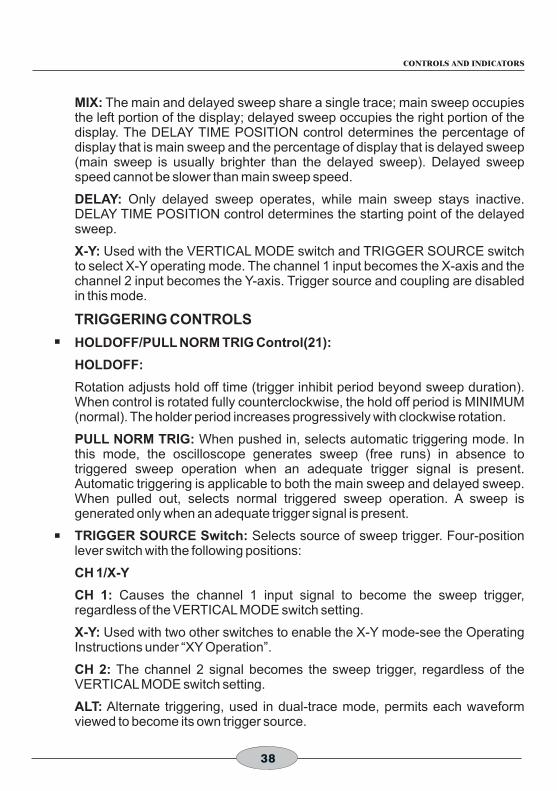
MIX: The main and delayed sweep share a single trace; main sweep occupies the left portion of the display; delayed sweep occupies the right portion of the display. The DELAY TIME POSITION control determines the percentage of display that is main sweep and the percentage of display that is delayed sweep (main sweep is usually brighter than the delayed sweep). Delayed sweep speed cannot be slower than main sweep speed.
DELAY: Only delayed sweep operates, while main sweep stays inactive. DELAY TIME POSITION control determines the starting point of the delayed sweep.
X-Y: Used with the VERTICAL MODE switch and TRIGGER SOURCE switch to select X-Y operating mode. The channel 1 input becomes the X-axis and the channel 2 input becomes the Y-axis. Trigger source and coupling are disabled in this mode.
TRIGGERING CONTROLS
HOLDOFF/PULL NORM TRIG Control(21):
HOLDOFF:
Rotation adjusts hold off time (trigger inhibit period beyond sweep duration). When control is rotated fully counterclockwise, the hold off period is MINIMUM (normal). The holder period increases progressively with clockwise rotation.
PULL NORM TRIG: When pushed in, selects automatic triggering mode. In this mode, the oscilloscope generates sweep (free runs) in absence to triggered sweep operation when an adequate trigger signal is present. Automatic triggering is applicable to both the main sweep and delayed sweep. When pulled out, selects normal triggered sweep operation. A sweep is generated only when an adequate trigger signal is present.
TRIGGER SOURCE Switch: Selects source of sweep trigger. Four-position lever switch with the following positions:
CH 1/X-Y
CH 1: Causes the channel 1 input signal to become the sweep trigger, regardless of the VERTICAL MODE switch setting.
X-Y: Used with two other switches to enable the X-Y mode-see the Operating Instructions under “XY Operation”.
CH 2: The channel 2 signal becomes the sweep trigger, regardless of the VERTICAL MODE switch setting.
ALT: Alternate triggering, used in dual-trace mode, permits each waveform viewed to become its own trigger source.
38
CONTROLS AND INDICATORS

EXT: Signal from EXTERNAL TRIGGER jack becomes sweep trigger.
Trigger COUPLING Switch(24): Selects trigger coupling. Four-position level switch with the following positions:
AC: Trigger signal is capacitively coupled.
TV-V: Used for triggering from television vertical sync pulses. Also serves as lo-pass/dc (high frequency reject) trigger coupling.
TV-H: Used for triggering from television horizontal sync pulses. Also serves as hi-pass (low frequency reject) trigger coupling.
LINE: Signal derived from input line voltage(50/60 Hz) becomes trigger.
TRIGGER LEVEL/PULL (-) SLOPE Control(26):
TRIGGER LEVEL: Trigger level adjustment; determines the point on the triggering waveform where the sweep is triggered. Rotation in the (-) direction (counterclockwise) selects more negative triggering point; rotation in the (=) direction (clockwise) selects more positive triggering (clockwise) selects more positive triggering point.
PULL (-) SLOPE: Two-position push-pull switch. The “in” position selects a positive-going slope and the “out: position selects a negative-going slope as triggering point for main sweep.
EXTERNAL TRIGGER Jack(16): External trigger input for single- and dual trace operation.
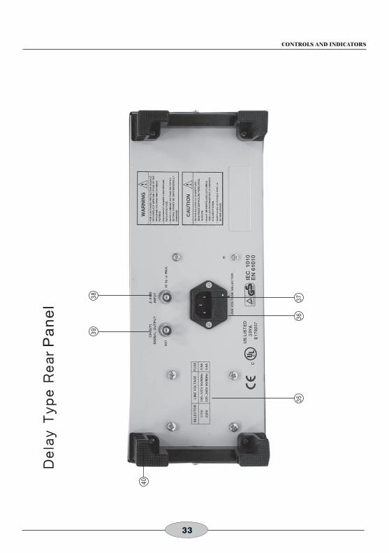
REAR PANEL CONTROLS (P.29~30)
Fuse Holder/Line Voltages Selector(35)(36): Contains fuse and selects line voltage.
Power Cord Receptacle.
CH 2 (Y) SIGNAL OUTPUT Jack(39): Output terminal where sample of channel 2 signal is available. Amplitude of output is nominally 50 mV per division of vertical deflection seen on CAR when terminated into 50Ω.
Z-Axis Input Jack(38): Input jack for intensity modulation of CRT electron beam. TTL compatible (5V p-p sensitivity). Positive levels increase intensity.
AC Power Input Connector(37).
Feet/Cord Wrap(40).
39
CONTROLS AND INDICATORS

Operating Instructions OSCILLOSCOPE INSTRUCTION MANUAL
40
1. When he oscilloscope is used to make measurements in equipment that contains high voltage, there is always a certain amount of danger from electrical shock. The person using the oscilloscope in such conditions should be a qualified electronics technician or otherwise trained and qualified to work in such circumstances. Observe the TEST INSTRUMENT SAFETY recommendations listed on the inside front cover of this manual.
2. Do not operate this oscilloscope with the case removed unless you are a qualified service technician. High voltage up to 1250 voltages is present when the unit is operating with the case removed.
3. The ground wire of the 3-wire ac power plug places the chassis and housing of the oscilloscope at earth ground. Use only a 3-wire outlet, and do not attempt to defeat the ground wire connection or float the oscilloscope; to do so many pose a great safety hazard.
4. Special precautions are required to measure or observe line voltage waveforms with any oscilloscope. Use the following procedure:
a. Do not connect the ground clip of the probe to either side of the line. The clip is already at earth ground and touching it to the hot side of the line may “weld” or disintegrate” the probe tip and cause possible injury, plus possible damage to the scope or probe.
b. Insert the probe tip into one side of the line voltage receptacle, then the other. One side of the receptacle should be “hot” and produce the waveform. The other side of the receptacle is the ac return and no waveform should result.
EQUIPMENT PROTECTION PRECAUTIONS
The following precautions will help avoid damage to the oscilloscope:
1.Never allow a small spot of high brilliance to remain stationary on the screen for more than a few seconds. The screen may become permanently burned. A spot will occur when the scope is set up for X-Y operation and no signal is applied. Either reduce the intensity so the spot is barely visible, apply signal, or switch back to normal sweep operation. It is also advisable to use low intensity with AUTO triggering and no signal applied for long periods. A high intensity trace at the same position could cause a line to become permanently burned onto the screen.
WARNING!
The following precautions must be observed to help prevent electric
shock:
SAFETY PRECAUTIONS

2741
2. Do not obstruct the ventilating holes in the case, as this will increase the scope's internal temperature.
3. Excessive voltage applied to the input jacks may damage the oscilloscope. The maximum ratings of the inputs are as follows:
4. Always connect a cable from the ground terminal of the oscilloscope to the chassis of the equipment under test. Without this precaution, the entire current for the equipment under test may be drawn through the probe clip leads under certain circumstances. Such conditions could also pose a safety hazard, which the ground cable will prevent.
5. The probe ground clips are at oscilloscope and earth ground and should be connected only to the earth ground or isolated common of the equipment under test. To measure with respect to any point other than the common, use CH 2-CH 1 subtract operation, with the channel 2 probe to the point of measurement and the
OPERATING INSTRUCTIONS
Input Terminal Maximum Allowable Input Voltage
CH1, CH2 Input 400 Vpeak (DC+AC peak)
EXT TRIG Input 300 Vpeak (DC+AC peak)
Probe Input (x10) 600 Vpeak (DC+AC peak)
Z-Modulation Input 30 Vpeak (DC+AC peak)

42
OPERATING INSTRUCTIONS
OPERATING TIPS
The following recommendations will help obtain the best performance from the oscilloscope.
1. Always use the probe ground clips for best results, attached to a circuit ground point near the point of measurement. Do not rely solely on an external ground wire in lieu of the probe ground clips as undesired signals may be introduced.
2. Avoid the following operations:
(1)Direct sunlight.
(2)High temperature and humidity.
(3)Mechanical vibration.
(4)Electrical noise and strong magnetic fields, such as near large motors power supplies, transformers, etc.
3. Occasionally check trace rotation, probe compensation, and calibration accuracy of the oscilloscope using the procedures found in the MAINTENANCE section of this manual.
4. Terminate the output of a signal generator into its characteristic impedance to minimize ringing, especially if the signal has fast edges such as square waves or
pulses. For example, the typical 50Ω output of a square wave generator should be
terminated into an external 50Ω terminating load and connected to the
oscilloscope with 50Ω coaxial cable.
5. Probe compensation adjustment matches the probe to the input of the scope. For best result, compensation should be adjusted initially, then the same probe always used with the same channel. Probe compensation should be readjusted when a probe from a different oscilloscope is used.
INITIAL STARTING PROCEDURE
Until you familiarize yourself with the use of all controls, the settings given here can be used as a reference point to obtain a trace on the CRT in preparation for waveform observation.
1. Set these controls as follows:
VERTICAL MODE to CH 1.
CH 1 AC/GND/DC to GND.
Select AUTO triggering(HOLD OFF pushed in), Trigger COUPLING to AC.

43
OPERATING INSTRUCTIONS
All POSITION controls and INTENSITY control centered(pointers facing up).
Main Time Base CONTROL TO 1 mS/DIV.
Sweep Mode switch to MAIN.
2. Press the red POWER pushbutton.
3. A trace should appear on the CRT. Adjust the trace brightness with the INTENSITY control, and the trace sharpness with the FOCUS control.
4. Use the BEAM Finder pushbutton to locate a trace that has been moved off the screen by the POSITION controls. When the button is pushed, a compressed version of the trace is brought into view which indicates the location of the trace.
5. When viewing audio and low frequency waveforms below 20 MHz, A better waveform may be obtained by engaging the 20 MHz/100 MHz pushbutton. This limits the bandwidth to 20 MHz and filters out high frequency noise and interference. For waveforms above 20 MHz, the pushbutton must be released to the 100 MHz position.(100MHz Oscilloscope )
SINGLE TRACE DISPLAY
Either channel 1 or channel 2 may be used for single-trace operation. To observe a waveform on channel 1:
1. Perform the steps of the “Initial Starting Procedure”.
2. Connect the probe to the CH 1(X) input jack.
3. Connect the probe ground clip to the chassis or common of the equipment under test. Connect the probe tip to the point of measurement.
4. Move the CH 1 AC/GND/DC switch out of the GND position to either DC or AC.
5. If no waveforms appear, increase the sensitivity by turning the CH 1 VOLTS/DIV control clockwise to a position that gives 2 to 6 divisions vertical deflection.
6. Position the waveform vertically as desired using the CH 1 POSITION control.
7. The display on the CRT may be unsynchronized. Refer to the “Triggering” paragraphs in this section for procedures on setting triggering and sweep time controls to obtain a stable display showing the desired number of waveforms.
DUAL TRACE DISPLAY
In observing simultaneous waveforms on channel 1 and 2, the waveforms are usually related in frequency, or one of the waveforms is synchronized to the other, although the basic frequencies are different. To observe two such related waveforms simultaneously, perform the following:

44
OPERATING INSTRUCTIONS
1. Connect probes to both the CH 1(X) and CH 2(Y) input jacks.
2. Connect the ground clips of the probes to the chassis or common of the equipment under test. Connect the tips of the probed to the two points in the circuit where waveforms are to be measured.
3. To view both waveforms simultaneously, set the VERTICAL MODE switch to DUAL and select either ALT (alternate) or CHOP with the PULL CHOP switch.
4. In the ALT sweep mode (PULL CHOP switch pushed in), one sweep displays the channel 1 signal and the next sweep displays the channel 2 signal in an alternating sequence. Alternate sweep is normally used for viewing high-frequency or high-speed waveforms at sweep times of 1 ms/DIV and faster, but may be selected at any sweep time.
5. In the CHOP sweep mode (PULL CHOP switch pilled out), the sweep is chopped (switched) between channel 1 and channel 2. Using CHOP, one channel does not have to “wait” for a complete swept display of the other channel. Therefore, portions of both channel's waveforms are displayed with the phase relationship between the two waveforms unaltered. Chop sweep is normally used for low-frequency or low-speed waveforms at sweep times of 1 ms/DIV and slower; or where the phase relationship between channel 1 and channel 2 requires measurement.
If chop sweep is used at sweep times of 0.2 ms/DIV and faster, the chop rate becomes a significant portion of the sweep and may become visible in the displayed waveform. However, you may select chop sweep at any sweep time for special applications.
6. Adjust the channel 1 and 2 POSITION controls to place the channel 1 trace above the channel 2 trace.
7. Set the CH 1 and CH 2 VOLTS/DIV controls to a position that gives 2 to 3 divisions of vertical deflection for each trace. If the display on the screen is unsynchronized, refer to the “Triggering” paragraphs in this section of the manual of procedures for setting triggering and sweep time controls to obtain a stable display showing the desired number of waveforms.
8. When the VERTICAL MODE switch is set to ADD, the algebraic sum of CH 1 + CH 2 is displayed as a single trace. When the PULL INV switch is pulled out, the algebraic difference of CH 1 CH 2 is displayed.
9. If two waveforms have no phase no phase or frequency relationship, there is seldom reason to observe both waveforms simultaneously. However, these oscilloscopes do permit the simultaneous viewing of two such unrelated waveforms, using alternate triggering. Refer to the paragraphs on “Triggering Trigger SOURCE Switch”, for details on alternate triggering.

45
OPERATING INSTRUCTIONS
TRIGGERING
The oscilloscope provides versatility in sync triggering for ability to obtain a stable, jitter-free display in single-trace, or dual-trace operation. The proper settings depend upon the type of waveforms being observed and the type of measurement desired. An explanation is given to help you select the proper setting over a wide range of conditions.
AUTO or NORM Triggering
1. In the AUTO triggering mode. (PULL NORM TRIG switch pushed in), automatic sweep operation is selected. In automatic sweep operation, the sweep generator free-runs to generate a sweep without a trigger signal. However, it automatically switches to triggered sweep operation if an acceptable trigger source signal is present. The AUTO position is handy when first setting up the scope to observe a waveform; it provides sweep for waveform observation until other controls can be properly set. Once the controls are set, operation is often switch back to the normal triggering mode, since it is more sensitive. Automatic sweep must be use for dc measurements and signals of such low amplitude that they will not trigger the sweep.
2. In the NORM triggering mode (PULL NORM TRIG switch pulled out), normal triggered sweep operation is selected. The sweep remains at rest until the selected trigger source signal crosses the threshold level set by the TRIG LEVEL control. The trigger causes one sweep to be generated, after which the sweep again remains at rest until triggered. In the normal triggering mode, there will be no trace unless an adequate trigger signal is present. In the ALT VERTICAL MODE of dual-trace operation with the SOURCE switch also set to ALT, there will be no trace unless both channel 1 and channel 2 signals are adequate for triggering. Typically, signals that produce even one division of vertical deflection are adequate for normal triggered sweep operation.
Trigger COUPLING Switch
1. The AC position is used for most waveforms except video. The trigger signal is capacitvely coupled. Thus, it blocks the dc component and references the “changing” position of the waveform.
2. The TV H and TV V positions are primarily for viewing composite video waveforms. Horizontal sync pulses are selected as trigger when the trigger COUPLING switch is set to the TV-H position, and vertical sync pulses are selected as trigger when the trigger COUPLING switch is set to the TV V position. The TV H and TV V position may also be used as low frequency reject and high frequency reject coupling, respectively. Additional procedures for observing video waveforms are given later in this section of the manual.

46
OPERATING INSTRUCTIONS
Trigger SOURCE Switch
The trigger SOURCE switch (CH 1, CH 2, etc.) selects the signal to be used as the sync trigger.
1. If the SOURCE switch is set to CH 1 (CH 2) the channel 1 (or channel 2) signal becomes the trigger source regardless of the VERTICAL MODE selection. CH 1, or CH2 are often used as the trigger source for phase or timing comparison measurements.
2. By setting the SOURCE switch to ALT, alternation triggering mode is activated. In this mode, the trigger source alternates between CH 1 and CH 2 with each sweep. This is convenient for checking amplitudes, wave shape, or waveform period measurements, and even permits simultaneous observation of two waveforms which are not related in frequency period. However, this setting is not suitable for phase or timing comparison measurements. For such measurements, both traces must be triggered by the same sync signal. Alternate triggering can only be used in dual-trace mode (VERT MODE set to DUAL), and with alternate sweep only (PULL CHOP not engaged).
3. In the EXT position of the COUPLING switch, the signal applied to the EXT TRIG jack becomes the trigger source. This signal must have a timing relationship to the displayed waveforms for a synchronized display.
4. In the LINE position of the COUPLING switch triggering is derived from the input line voltage (50/60 Hz) and the trigger SOURCE switch is disabled. This is useful for measurements that are related to line frequency.
TRIG LEVER Control
The TRIG LEVEL control adjusts the start of the sweep to almost any desired point on a waveform. On sine wave signals, the phase at which sweep begins is variable toward its extreme + or - setting, no sweep will be developed in the normal trigger mode because the triggering threshold exceeds the peak amplitude of the sync signal.
SLOP Switch
This switch selects the slope (polarity) of the triggering signal.
Push down the switch to be set in the “+” state, triggering occurs as the triggering signal crosses the triggering level in the direction of signal increase (i.e, positive direction).
Pull up the switch to be set in the “-“ state, triggering occurs as triggering signal crosses the triggering level in the direction of signal decrease(i.e, negative direction).
+
-
Pos i t ive-g ing s lope
Negat ive-g ing s lope

47
OPERATING INSTRUCTIONS
HOLD OFF Control
Controls hold-off time between sweep signals to obtain stable display when triggering a periodic signal. The control hold time ranges from 1 to 5 times time base.
Refer to Fig.3(A): shows a case for HOLD OFF knob at the NORM position. Various different waveforms are overlapped on the screen, making the signal observation unsuccessful.
Refer to Fig.3(B): show a case in witch the undesirable portion of the signal is held off.
The same waveforms are displayed on the screen without overlapping.
In such a case, the sweep can be stable synchronized to the HOLD OFF time (sweep pause time) of the sweep waveform.
TIME BASE Control
1. Sweep TIME/DIV Control
Set the sweep TIME/DIV control to display the desired number of cycles of the waveform. If there are too many cycles displayed for good resolution, switch to faster sweep time. If only a line is displayed, try a slower sweep time. When the sweep time is faster than the waveform being observed, only part of it will be displayed, which may appear as a straight line for a square wave or pulse waveform.
Adjusting the HOLD OFF
time
Sweep Waveform
A complex waveform(Digital signal)
Cycle
Heavy parts are display
Fig.3
(A)
(B)

48
OPERATING INSTRUCTIONS
2. Sweep Magnification
When a certain position of the displayed waveform is needed to be expanded time wise, a faster sweep speed may be used. However, if the required portion is far from the starting point of the sweep, the required portion may run off the CRT screen. In such a case, pull out (set in the x10 MAG state) the POSITION switch KNOB. When this is done, the displayed waveform is expanded by 10 times to right or left with the center of screen at the center of expansion.
The sweep time during the magnification operation is obtained as follows:
(Value indicated by TIME/DIV switch) x 1/10. Thus, the unmagnified maximum sweep speed (0.1μ sec/DIV) can be made faster with magnification as follows:
0.1μsec/DIV x 1/10 = 10 nsec/DIV
When the sweep is magnified and the sweep speed has become faster than 0.1 sec/DIV, the trace may become darker.
3. MAIN/MIX/DELAY Switch
When turn the switch to MAIN position, the waveform of display on the screen is main sweep only.
When turn the switch to MIX position, the waveform of display on the screen is shown in Fig.5.
10 x magnification
Fig.4 Any part can be covered by meansof POSITION control.
Start point C mixed point
A BFig.5

49
OPERATING INSTRUCTIONS
The portion of A is main sweep which is set by the MAIN TIMEBASE. The portion of B is delay sweep witch is set by the DELAY TIME BASE. The mixed point C is continuously variable by means of the DELAY TIME POSITION switch.
When turn the switch to DELAY position. A portion of Fig.5 disappears, the mixed point C replaces the position of starting point and B portion of Fig 5 display only the screen.
NOTE: DELAY TIMEBASE must be faster than MAIN TIMEBASE and not exceed 10 times.
X-Y OPERATION
X-Y operation permits the oscilloscope to perform many measurements not possible with conventional sweep operation. The CRT display becomes an electronic graph of two instantaneous voltages. The display may be a direct comparison of the two voltages such as stereoscope display of stereo signal output. However, the X-Y mode can be used to graph almost any dynamic characteristic if a transducer is used to change the characteristic (frequency, temperature, velocity, etc.) into a voltage. One common application is frequency response measurements, where the Y-axis corresponds to signal amplitude and the X-axis corresponds to frequency.
1. Press the X-Y switch. In this mode, channel 1 becomes the X-axis input and channel 2 becomes the Y-axis input. All VERTICAL MODE switch should be disengaged for X-Y operation.
2. The X and Y positions are now adjusted using the X POSITION and the 2 POSITION controls respectively.
3. Adjust the amount of vertical (Y-axis) deflection with the CH 2 VOLTS/DIV and VARIABLE controls.
4. Adjust the amount of horizontal (X-axis) deflection with the CH 1 VOLTS/DIV and VARIABLE controls.
COMPONENT TEST
1. Press in COMP TEST pushbutton to place oscilloscope in component test operating mode.
2. Disconnect CH 1 AND CH 2 input connectors.
3. Insert diode or zener diode, LED, capacitor, LED, capacitor, etc., between COMP TEST socket and ground.
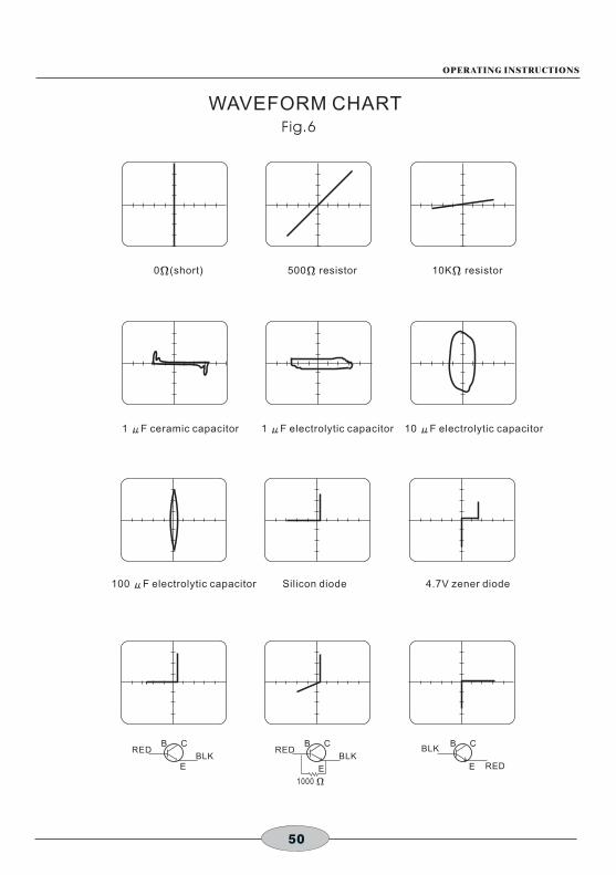
4. Verify that displayed waveform are similar to the Test Patterns shown in Fig.6.
5. When you have finished component testing, press COMP TEST pushbutton to out position. This disables component test mode operation.
50
WAVEFORM CHART
REDB C
EBLK
REDB C
E
BLK
1000 Ω
RED
B C
E
BLK
0 (short)Ω 500 resistorΩ 10K resistorΩ
1 F ceramic capacitorμ 1 F electrolytic μ capacitor 10 F electrolytic μ capacitor
100 F electrolytic capacitorμ Silicon diode 4.7V zener diode
Fig.6
OPERATING INSTRUCTIONS

Application OSCILLOSCOPE INSTRUCTION MANUAL
51
DC VOLTAGE MEASUREMENTS
(Refer to Fig.7)
The following technique may be used to measure the instantaneous de level at any portion of a waveform, or to measure a dc voltage where no waveform is present.
1. Connect the signal to be measured to the input jack and set the CH 1/ CH 2 switch to the channel to be used. Set the COLTS/DIV and sweep TIME/DIV controls to obtain a normal display of the waveform to be measured. The VARIABLE control must be set to CAL.
2. Set the COUPLE switch to AUTO and the AC-GND-DC switch to GND. This establishes a trace at the zero volt reference. Using the POSITION control, adjust the trace to the desired reference level position, making sure not to disturb this setting once made.
3. Set the AC-GND-DC switch to DC to observe the waveform, including its dc component. If an inappropriate reference level position was selected in set 2 or an inappropriate VOLTS/DIV setting was made, the waveform may not be visible at this point (deflected completely off the screen). This is especially true when the dc component is large with respect to the waveform amplitude. If so, reset the VOLTS/DIV control and repeat steps 2 and 3 until the waveform and the zero reference are both on the screen.
4. Use the X POSITION control to bring the portion of the waveform to be measured to the center vertical graduation line of the graticule scale.
5. Measure the vertical distance from the zero reference level to the point to be measured (at least 3 divisions desirable for best accuracy). The reference level can be rechecked by momentarily returning the AC-GND DC switch to GND.
6. Multiply the distance measured above by the VOLTS/DIV setting and the probe attenuation ratio as well. Voltages above the reference level are positive and voltages below the reference level are negative.
The measurement is summarized by the following equation:
DC level + Vert div x VOLTS/DIV x Probe
For the example shown in Fig.7, the point being measured is 3.8 divisions from the reference level (ground potential). If the VOLTS/DIV control is set to 0.2 V and a 10:1 probe is used, the dc voltage level is calculated as follows:
DC level = 3.8 (div) x 0.2 (V/div) x 10 = 7.6V

52
APPLICATION
MEASUREMENT OF VOLTAGE BETWEEN TWO POINT ON A WAVEFORM
(Refer to Fig.8)
This procedure may be used to measure peak-to peak voltages, or for measuring the voltage difference between any two points on a waveform.
1. Connect the signal to be measured to the input connector, set the CH 1/CH 2 switch to the channel to be used, and set the AC-GND-DC switch to AC. Set the VOLTS/DIV and sweep TIME/DIV controls to obtain a normal display of the waveform to be measured. The VARIABLE control must be set to CAL.
2. Using the X POSITION control, adjust the waveform position such that one of the row points falls on a major horizontal graduation line.
3. Using the X POSITION control, adjust the second point to coincide with the center vertical graduation line.
4. Measure the vertical distance between the two points( at least 3 divisions desirable for best accuracy). Multiply the number of divisions by the setting of the VOLTS/DIV control. If a probe is used, further multiply this by the probe attenuation ratio.
The measurement is summarized by the following equation:
Voltage = Vert div x VOLTS/DIV x probe
100
90
10
0
Measuring point adjusted to the center vertical scale by position
Ground potential adjusted by POSITION (reference line)
100
90
10
0
Adjust to the center vertical scale with POSITION
Points to be measured
Adjust to the horizontalscale with POSITION
Fig.7 DC Voltage Measurement Fig.8 Voltage Measurement
Ve
rtic
al d
ista
nce
Ve
rtic
al d
ista
nce
be
twe
en
two
po
ints

53
APPLICATION
Fir the example shown in Fig.8, the two points are separated by 4.4 divisions vertically. If the VOLTS/DIV setting is 20 mV and a 10:1 probe is used, the voltage is calculated as follows:
Voltage = 4.4 (div) x 20 (mV/DIV) x 10 = 880 mV
TIME MEASUREMENTS
(Refer to Fig.9)
This is the procedure for Making time (period) measurements between two points on a waveform. The two point may be the beginning and ending of one complete cycle if desired.
1. Connect the signal to be measured to the input connector and set the CH 1/CH 2 switch to the channel to be used. Set the VOLTS/DIV and sweep TIME/DIV controls to obtain a normal display of the waveform to be measured. Be sure the VAR SWEEP control is set to CAL.
2. Using the POSITION control, set one of the points to be used as a reference to coincide with the horizontal center line. Use the X POSITION control to set this point at the intersection of any vertical graduation line.
3. Measure the horizontal distance between the two point (at least 4 divisions desirable for best accuracy). Multiply this by the setting of the sweep TIME/DIV control to obtain the time between the two points. If x10 magnification is used, multiply this further by 1/10.
The measurement is summarized by the following equation:
Time = Hor div x TIME/DIV
(x 1/10 if X10 is used)
100
90
10
0
Horizontal distance
Fig.9 Time Measurement
Adjust to the vertical scale with POSITION
Adjust to the horizontalcenter line with POSITION

54
APPLICATION
For the example shown in Fig.9, the horizontal distance between the two points is 5.4 divisions. If the TIME/DIV is 0.2 ms and X10 magnification is not used, the time period is calculated as follows:
Time = 5.4 (div) x 0.2 (ms/div) = 1.08 ms
FREQUENCY MEASUREMENTS
Method No.1
(Refer to Fig.10)
Frequency measurements are made by measuring the time period of one cycle of waveform and calculating the frequency, witch equals the reciprocal of the time period.
1. Set up the oscilloscope to display one cycle of waveform (see Fig.10).
2. Measure the time period of one cycle and calculate the frequency as follows:
Freq = 1/Period
In the example shown in Fig.15, a period of 40 μs is observed. Substituting this value into the above equation, the frequency is calculated as follows:
Freq = = 2.5 x 14 = 25 kHz 1
4
40 x 16 -6
100
90
10
0
1 cycle=40 S/div x 8 div)μ
Fig.10 Frequency Measurement

55
APPLICATION
Method No.2
(Refer to Fig.11)
While the previously described method relies upon direct period measurement of one cycle, the frequency may also be measured by counting the number of cycles present in a given time period.
1. Set the oscilloscope to display several cycles of the waveform. The VAR SWEEP control must be set to CAL.
2. Count the number of cycles of waveform between a chosen set of vertical graduation lines.
3. Multiply the number of horizontal divisions by the sweep TIME/DIV setting to calculate the time sweep TIME/DIV setting to calculate the time span. Multiply the reciprocal of this value by the number of cycles present in the time span. If X10 magnification is used, multiply this further by 10. Note that errors will occur for displays having only a few cycles.
The measurement is summarized by the following equations:
Freq =
For the example shown in Fig.16, there are 10 cycles within 7 divisions. If the sweep TIME/DIV is 5 μ s and X10 magnification is not used, the frequency is calculated as follows:
Freq = = 285.7 kHz
100
90
10
0
Fig.10 Alternate Method Of Frequency Measurement
Count cycles between this portion
No of cycles ( x10 for x 10)
Hor div x TIM/DIV
10 (cycles)
7 (div) x 5 ( s)μ

56
APPLICATION
PULSE WIDTH MEASUREMENTS
(Refer to Fig.12)
1. Apply the pulse signal to the input jack and set the CH 1/CH 2 switch to the channel to be used.
2. Use the VOLTS/DIV and VARIABLE controls to adjust the display so the waveform is easily observed. Use the POSITION control to position the pulse over the center horizontal graduation.
3. Measure the distance between the leading edge and trailing edge of the pulse (along the center horizontal graduation line). Be sure that the VAR SWEEP control is set to CAL. Multiply the number of horizontal divisions by the sweep TIME/DIV, and if X10 magnification is used, further multiply this value by 1/10.
The measurement is summarized by the following equation:
Pulse Width = Hor div x TIME/DIV
(X 1/10 if X10 is used)
For the example shown in Fig.12, the pulse width at the center of the pulse is 4.6 divisions. If the sweep TIME/DIV is 0.2 ms and X10 magnification is used, the pulse width is calculated as follows:
100
90
10
0
Fig.12 Pulse Width Measurement
Pulse Length(at 50%)
Adjust to the vertical scale with POSITION
Align the waveformwith the centerusing POSITION

57
APPLICATION
PULSE RISE TIME AND FALL TIME MEASUREMENTS
(Refer to Fig.13)
For rise time and fall time measurements, the 10% and 90% amplitude point are used as starting and ending reference points.
1. Apply a signal to the input jack and set the CH 1/CH 2 switch to the channel to be used. Use the VOLTS/DIV and VARIABLE controls to adjust the waveform peak to peak height to six divisions.
2. Using the Y POSITION control, adjust the display so that the waveform is centered vertically on the display. Set the sweep TIME/DIV control to as fast a setting as possible while still being able to observe both the 10% and 90% points. Set the VAR SWEEP control to the CAL position.
3. Use the X POSITION control to adjust the 10% point to coincide with a vertical graduation line and measure the horizontal distance in divisions between the 10% and 90% points on the waveform. Multiply this by the sweep TIME/DIV setting and also by 1/10 if the X10 magnification mode was used.
NOTE:
Be sure that the correct 10% and 90% lines are used. For such measurements the 0, 10, 90 and 100% points are marked on the CRT screen.
The measurement is summarized by the following equation:
Rise Time = Hor div x TIME/DIV (x 1/10 if X10 is used)
For the example shown in Fig.13, the horizontal distance is 4.0 divisions. The sweep TIME/DIV setting is 2μ s. The rise time is calculated as follows:
Rise Time = 4.0 (div) x 2 (μs/div) = 8 μs
Fig.13 Rise Time andFall Time Measurement
100
90
10
0
Rise time
Adjust to the vertical scale with POSITION
58
APPLICATION
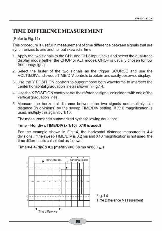
TIME DIFFERENCE MEASUREMENT
(Refer to Fig.14)
This procedure is useful in measurement of time difference between signals that are synchronized to one another but skewed in time.
1. Apply the two signals to the CH1 and CH 2 input jacks and select the dual-trace display mode (either the CHOP or ALT mode). CHOP is usually chosen for low frequency signals.
2. Select the faster of the two signals as the trigger SOURCE and use the VOLTS/DIV and sweep TIME/DIV controls to obtain and easily observed display.
3. Use the Y POSITION controls to superimpose both waveforms to intersect the center horizontal graduation line as shown in Fig.14.
4. Use the X POSITION control to set the reference signal coincident with one of the vertical graduation lines.
5. Measure the horizontal distance between the two signals and multiply this distance (in divisions) by the sweep TIME/DIV setting. If X10 magnification is used, multiply this again by 1/10.
The measurement is summarized by the following equation:
Time = Hor div x TIME/DIV (x 1/10 if X10 is used)
For the example shown in Fig.14, the horizontal distance measured is 4.4 divisions. If the sweep TIME/DIV is 0.2 ms and X10 magnification is not used, the time difference is calculated as follows:
Time = 4.4 (div) x 0.2 (ms/div) = 0.88 ms or 880 μs
Fig.14Time Difference Measurement
100
90
10
0
Time difference
Reference signal Comparison signal

59
APPLICATION
PHASE DIFFERENCE MEASUREMENTS
Method No.1
(Refer to Fig.15)
This procedure is useful in measuring the phase difference of signals of the same frequency.
1. Apply the two signals to the CH 1 and CH 2 input jacks, selecting the dual-trace display mode (either ALT or CHOP).
2. Set the trigger SOURCE switch to the signal witch is leading in phases (or to LINE if device is line voltage operated) and use VOLTS/DIV controls to adjust the two waveforms so they are equal in amplitude.
3. Use the Y POSITION control to position the waveforms in the vertical center of the screen. Use the TIME/DIV and VAR SWEEP controls to adjust the display so one cycle of the reference signal occupies 8 divisions horizontally (see Fig. ). The TRIG LEVEL and X POSITION controls are useful in achieving this display. The display should be as shown in Fig. , where one division now represents 45 in phase.
4. Measure the horizontal distance between corresponding points on the two waveforms. Multiply the distance (in division) time 45 per division to obtain the phase difference.
The measurement is summarized by the following equation:
Phase difference = Hor div x 45 /div
For the example shown in Fig.15, the horizontal distance is 1.7 divisions. Thus, the phase difference is calculated as follows:
Phase difference = 1.7 x 45 /div = 76.5
۱٥
۱٥ °
°
°
° °
Fig.15Phase Difference Measurement
100
90
10
0
1 cycle
Phase differenceComparison signal
Reference Signal

60
APPLICATION
Method No.2
(Refer to Fig.16)
The above procedure allows 45 per division, which may not give the desired accuracy for small phase differences.
If greater accuracy is required, the sweep TIME/DIV setting may be changed to expand the display as shown in Fig. , but the VAR SWEEP setting must not be to touched. If necessary, the TRIG LEVEL may be readjusted. For this type of operation, the relationship of one division to 45 no longer holds. Instead the following equation must be used:
Phase diff = Hor div x 45/div x
Where:
A = New TIME/DIV setting.
B = Original TIME/DIV setting.
A simpler method of obtaining more accuracy quickly is to simply use X10 magnification for a scale factor of 4.5 /division.
°
۱٦
°
°
Fig.16 Measuring Small Phase Difference
100
90
10
0
Phase difference
A
B
100
90
10
0
One cycle adjusted to 8 div.
Phase difference
Expanded sweep waveform display.
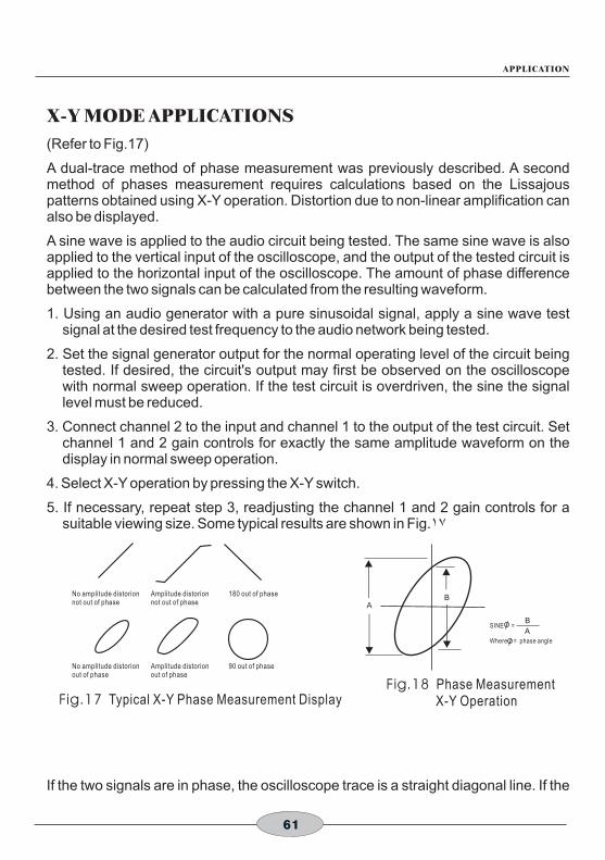
61
APPLICATION
X-Y MODE APPLICATIONS
(Refer to Fig.17)
A dual-trace method of phase measurement was previously described. A second method of phases measurement requires calculations based on the Lissajous patterns obtained using X-Y operation. Distortion due to non-linear amplification can also be displayed.
A sine wave is applied to the audio circuit being tested. The same sine wave is also applied to the vertical input of the oscilloscope, and the output of the tested circuit is applied to the horizontal input of the oscilloscope. The amount of phase difference between the two signals can be calculated from the resulting waveform.
1. Using an audio generator with a pure sinusoidal signal, apply a sine wave test signal at the desired test frequency to the audio network being tested.
2. Set the signal generator output for the normal operating level of the circuit being tested. If desired, the circuit's output may first be observed on the oscilloscope with normal sweep operation. If the test circuit is overdriven, the sine the signal level must be reduced.
3. Connect channel 2 to the input and channel 1 to the output of the test circuit. Set channel 1 and 2 gain controls for exactly the same amplitude waveform on the display in normal sweep operation.
4. Select X-Y operation by pressing the X-Y switch.
5. If necessary, repeat step 3, readjusting the channel 1 and 2 gain controls for a suitable viewing size. Some typical results are shown in Fig.۱۷
If the two signals are in phase, the oscilloscope trace is a straight diagonal line. If the
Fig.17 Typical X-Y Phase Measurement Display
No amplitude distorionnot out of phase
Amplitude distorionnot out of phase
180 out of phase
AB
SINE =
Where = phase angle
B
A
Fig.18 Phase Measurement X-Y Operation
No amplitude distorionout of phase
Amplitude distorionout of phase
90 out of phase

62
APPLICATION
FREQUENCY RESPONSE MEASUREMENTS
(Refer to Fig.19)
A sweep generator and the X-Y mode of this oscilloscope may be used to measure the audio or RF frequency response of an active or passive device up to 20 MHz, such as an amplifier, band pass filter, coupling network, etc.
1. Connect the audio or RF output of the sweep generator to the input of the circuit under test and the output of the test circuit to channel 2 (vertical axis) of the oscilloscope. A demodulator probe will give a “text book” frequency response display as shown in Fig.24, but a standard probe can be used which will result in an envelope display.
2. Connect the sweep ramp voltage of the sweep generator to the channel 1 input of the oscilloscope.
3. Set the X-Y switch to the X-Y position (engaged) and adjust the channel 1 and 2 controls for a suitable viewing size.
Fig.19 Frequency Response Measurement
4.08 MHz
3.58 MHz
3.08 MHz
90%±10%
VALLEY15% MAXTILT 10% MAX
4.50MHz
85%+15%, -20%

Maintenance OSCILLOSCOPE INSTRUCTION MANUAL
63
A following instruction are for use by qualified service personnel only. To avoid electrical shock, do not perform any servicing other contained in the operation instructions unless you are qualified to do so.
High voltage up to 1,250 volts is present when cover is removed and the unit is operating. Remember that high voltage may be retained indefinitely on high voltage capacitors. Also remember that ac line voltage is present on line voltage input circuits any time the instrument is plugged into an ac outlet, even if turned off. Unplug the oscilloscope and discharge high voltage capacitors before performing service procedures
FUSE REPLACEMENT
If the fuse blows, the “ON” indicator will not light and the oscilloscope will not operate. The fuse should not normally open unless a problem has developed in the unit. Try to determine and correct the cause of the blown fuse, then replace only with the correct value fuse. For 115V line voltage operation, use a 800 mA, 250V fuse. For 230V line voltage operation, use a 600mA, 250V fuse. The fuse is located on the rear panel adjacent to the power cord receptacle.
Remove the fuseholder assembly as follows:
1. Unplug the power cord from rear of scope.
2. Insert a small screwdriver in fuseholder slot (located between fuseholder and receptacle). Pry fuseholder away from receptacle.
3. When reinstalling fuseholder, be sure that the fuse is installed so that the correct line voltage is selected (see LINE VOLTAGE SELECTION).
LINE VOLTAGE SELECTION
To select the desired line voltage, simply insert the fuse and fuse holder so that the appropriate voltage is at the top (pointed to by the arrow). Be sure to use the proper value fuse (see label on rear panel.)
PERIODIC ADJUSTMENTS
Prove compensation and trace rotation adjustments should be checked periodically and adjusted if required. These Procedures are given below.
Probe Compensation
1. Connect probes to CH 1 to CH 2 input jacks. Perform procedure for each probe, one probe at a time.
WARNING!

64
MAINTENANCE
2. Set the probe to X10 (compensation adjustment is not possible in the X1 position).
3. Touch tip of probe to CAL terminal.
4. Adjust oscilloscope controls to display 3 or 4 cycles of CAL square wave at 5 or 6 divisions amplitude.
5. Adjust compensation trimmer on probe for optimum square wave (minimum overshoot, rounding off, and tilt). Refer to Fig.20:
Trace Rotation Adjustment
1. Set oscilloscope controls for a single trace display in CH 1 mode, and with the channel 1 AC-GND-DC switch set to GND.
2. Use the channel 1 POSITION control to position the trace over the center horizontal line on the graticule scale. The trace should be exactly with the horizontal line.
3. Use the TRACE ROTATION adjustment on the front panel to eliminate any trace tilt.
CALIBRATION CHECK
A general check of calibration accuracy may be made by displaying the output of the CAL terminal on the screen. This terminal provides a square wave of 2 Vp-p. This signal should produce displayed waveform amplitude of four divisions at 0.5 V/DIV sensitivity for both channel 1 and 2 (with probes set for direct). With probes set for X10, there should be four divisions amplitude at 50 mV/DIV sensitivity. The VARIABLE controls must be set to CAL during this check.
100
90
10
0
Correct Compensation
Over Compensation
Insufficient Compensation
Fig.20 Probe Compensation Adjustment

Block Diagram OSCILLOSCOPE INSTRUCTION MANUAL
65
CH
A
AT
T
CH
B
AT
T
CH
AP
RE
AM
P
TR
IG, X
-AIX
S P
ICK
OF
F A
MP
CH
BP
RE
AM
P
CO
MP
TE
ST
VE
RT
MO
DE
S
WIT
CH
BE
AM
FIN
DE
R
SW
ITC
HIN
GL
OG
IC
INT
TR
IG
SW
ITC
H
TR
IG
PIC
K O
FF
AM
P
CH
1(X
)IN
PU
T
CH
2(Y
)IN
PU
T
CH
2O
UT
PU
T
Z-A
XIS
MO
D
VE
RT
ICA
L O
UT
PU
TA
MP
Z-A
XIS
AM
PC
RT
CIR
CU
IT
HV
SU
PP
LY
CR
T
TR
IG I
NP
UT
AM
PT
RIG
GE
NE
RA
TO
R
AU
TO
CIR
CU
IT
LIN
E T
RIG
LIN
E
EX
T
INT
(X-Y
)
EXT TRIG
X-A
XIS
SIG
NA
L
MA
IN S
WE
EP
GE
NE
RA
TO
R
DE
LAY
SW
EE
PG
EN
ER
AT
OR
FO
R X
X5
ON
LY
HO
RIZ
ON
TAL
SW
ITC
HIN
G
HO
RIZ
ON
TAL
OU
TP
UT
AM
P
CA
LIB
RA
TO
RP
OW
ER
SU
PP
LYA
C L
INE
50
/60
Hz
TR
IG
SIG
NA
L
FR
EE
R
UN
S
IGN
AL
TO
E
AC
H
BL
OC
KS
2 V
p-p
1 kH
ZS
QU
AR
E W
AV
E


TINSE0050S4 Ver.01.1