orthopantomograph op200 d orthoceph oc200 d · tmj imaging • • • ... 20 s 27. – 141 . s 01....
TRANSCRIPT

1
ORTHOPANTOMOGRAPH® OP200 DORTHOCEPH® OC200 D
VT – Volumetric Tomography
OP2
00 D
• O
C200
D •
VT
Dig
ital p
anor
amic
imag
ing
syste
m
Dig
ital c
epha
lom
etric
imag
ing
syste
m
VT –
Vol
umet
ric T
omog
raph
y
2 3
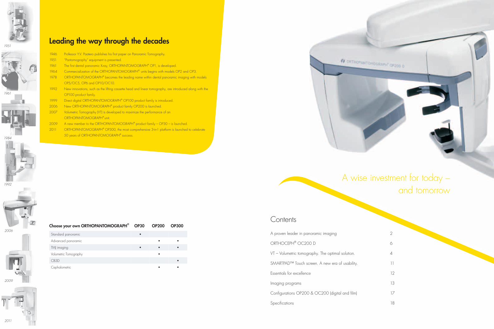
1946 Professor Y.V. Paatero publishes his first paper on Panoramic Tomography.
1951 “Pantomography” equipment is presented.
1961 The first dental panoramic X-ray, ORTHOPANTOMOGRAPH® OP1, is developed.
1964 Commercialization of the ORTHOPANTOMOGRAPH® units begins with models OP2 and OP3.
1978 ORTHOPANTOMOGRAPH® becomes the leading name within dental panoramic imaging with models
OP5/OC5, OP6 and OP10/OC10.
1992 New innovations, such as the lifting cassette head and linear tomography, are introduced along with the
OP100 product family.
1999 Direct digital ORTHOPANTOMOGRAPH® OP100 product family is introduced.
2006 New ORTHOPANTOMOGRAPH® product family OP200 is launched.
2007 Volumetric Tomography (VT) is developed to maximize the performance of an
ORTHOPANTOMOGRAPH® unit.
2009 A new member to the ORTHOPANTOMOGRAPH® product family – OP30 – is launched.
2011 ORTHOPANTOMOGRAPH® OP300, the most comprehensive 3-in-1 platform is launched to celebrate
50 years of ORTHOPANTOMOGRAPH® success.
Leading the way through the decades
Choose your own ORTHOPANTOMOGRAPH® OP30 OP200 OP300
Standard panoramic •
Advanced panoramic • •
TMJ imaging • • •
Volumetric Tomography •
CB3D •
Cephalometric • •
A proven leader in panoramic imaging 2
ORTHOCEPH® OC200 D 6
VT – Volumetric tomography. The optimal solution. 4
SMARTPAD™ Touch screen. A new era of usability. 11
Essentials for excellence 12
Imaging programs 13
Configurations OP200 & OC200 (digital and film) 17
Specifications 18
Contents
A wise investment for today – and tomorrow

4 5
AA proven leader in panoramic imaging
Accurate and stable patient positioningCorrect patient positioning is assured by three positioning laser lights. Frankfurt and midsagittal lights aid finding the correct angulation of the patient’s head and the occlusion correction light ensures proper anterior positioning.
A rigid 5-point positioning system including forehead support, chin rest and bite fork eliminates patient movement. The open design allows easy viewing and positioning of the patient from either the left or right side.
V-shaped beam – clinically proven imaging geometryThe V-shaped X-ray beam adapts to the human anatomy, providing even greater detail and a wider mandibular image layer. The V-shaped X-ray beam also allows for more penetrating power for the thicker maxilla area.
Partial programs – Decrease of doseWhen a full panoramic image is not required, 1 to 5 segments of the horizontal image can be selected to expose only regions of diagnostic interest.
Correct imaging values – automaticallyOP200 has a patented method for dose-controlled Automatic Exposure Control. The system measures patient bone thickness from the ramus and defines individual exposure values for patients with different sizes. This also enables individual Automatic Spine Compensation values to reduce spinal shadow in the image for each patient.
Special geometryThe Ortho Zone program provides a special geometry to solve two common imaging problems: metal artefacts in the molar region of the condyle, and the need for an exceptionally wide anterior layer for patients with malocclusion.
Wider mandibular layer
Benefits of V-shaped beam
More penetrating power
Standardbeam
V-shapedbeam
A V-shaped beam supports better imaging of the human anatomy than a standard beam and ensures a homogeneous image.

6 7
OORTHOCEPH® OC200 D
Fully adjustable scanningOC200 D incorporates an advanced user-adjustable lateral scan method to expose only the desired portion of the skull. This method reduces the scanning time to a minimum of 5 seconds and reduces patient dose considerably.
OC200 D uses a patented Automatic Facial Contour (AFC) method for soft tissue enhancement in lateral views. The unit automatically adjusts the exposure values during scanning for better soft tissue definition.
Clinically correct image geometryIn order to produce equal and accurate horizontal and vertical magnification, OC200 D uses a patented method of synchronized tube head horizontal sweep and sensor movements while keeping the focal spot in the same position.
48% to 62% dose reduction
Full range of projectionsORTHOCEPH® patient positioning system provides a variety of imaging projections for cephalometric radiography. It is a comprehensive diagnostic device that includes lateral, facial, posterioranterior and oblique projections, as well as the possibility of hand and wrist imaging.
Perfect fit for your clinicOC200 D can be set up in your clinic for right- or left-handed cephalometric imaging and is “field changeable”. SMARTPAD™ can be installed on either side of the unit or on the wall.
Stable patient positioningThe Frankfurt horizontal plane laser light, nasion support and rigid ear rods with locking system make patient positioning easy and convenient.
100% dose, typical full scan digital cephalostat
52 – 38% dose with Lateral Ceph standard
Area of lowered AFC dose
Area of lowered AFC dose
Only 43 – 32% dose with the new Core Lateral Ceph
8 9
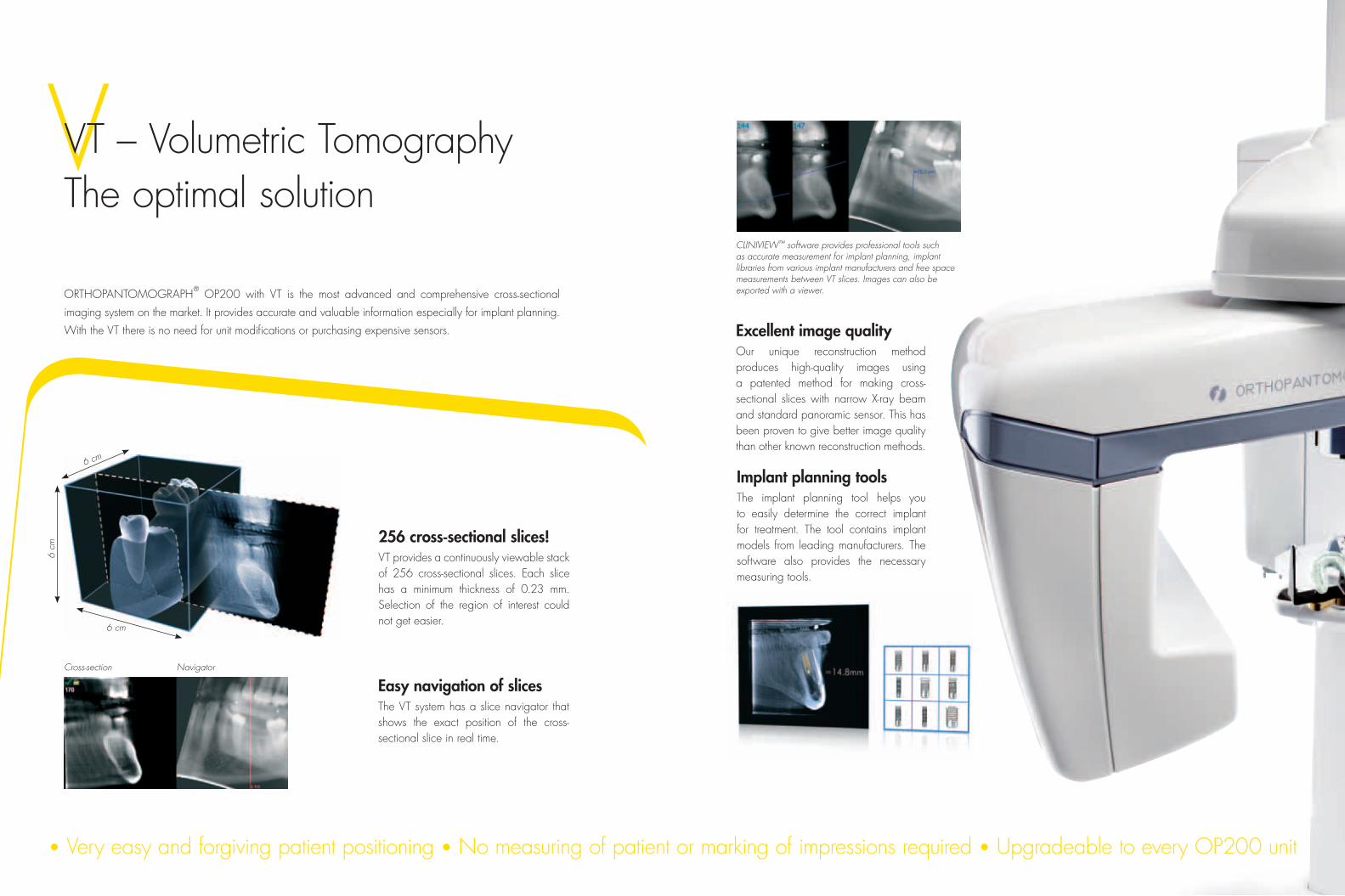
VVT – Volumetric TomographyThe optimal solution
ORTHOPANTOMOGRAPH® OP200 with VT is the most advanced and comprehensive cross-sectional
imaging system on the market. It provides accurate and valuable information especially for implant planning.
With the VT there is no need for unit modifications or purchasing expensive sensors.
256 cross-sectional slices!VT provides a continuously viewable stack of 256 cross-sectional slices. Each slice has a minimum thickness of 0.23 mm. Selection of the region of interest could not get easier.
CLINIVIEW™ software provides professional tools such as accurate measurement for implant planning, implant libraries from various implant manufacturers and free space measurements between VT slices. Images can also be exported with a viewer.
Implant planning toolsThe implant planning tool helps you to easily determine the correct implant for treatment. The tool contains implant models from leading manufacturers. The software also provides the necessary measuring tools.
6 cm
6 cm
6 cm
Excellent image qualityOur unique reconstruction method produces high-quality images using a patented method for making cross-sectional slices with narrow X-ray beam and standard panoramic sensor. This has been proven to give better image quality than other known reconstruction methods.
Easy navigation of slicesThe VT system has a slice navigator that shows the exact position of the cross-sectional slice in real time.
Cross-section Navigator
• Very easy and forgiving patient positioning • No measuring of patient or marking of impressions required • Upgradeable to every OP200 unit

10 11
ASMARTNAV™ – Interactive navigatorSMARTNAV™ navigation software provides easy selection of imaging programs, arch sections, lateral scanning start position, and more. The user can easily set the desired imaging parameters in SMARTNAV™. All information is displayed and described in an intuitive manner.
A new era of usability
SMARTPAD™ full-color touch screenThe large 12.1” SMARTPAD™ touchscreen has an easy- to-use menu with simple and intuitive navigation. SmartPad™ option is available for all OP200 D units.
Patient positioning animationsIf in doubt, patient positioning animations specific to each imaging program demonstrate the proper patient positioning procedure.
Instant dynamic help This feature provides quick and convenient information related to the imaging programs, such as the purpose of the program selected.
11
Operators of the unit and their knowledge of the imaging methods may change with time
– quality of ORTHOPANTOMOGRAPH® and ORTHOCEPH® images will not.

12 13
IImaging programs
Versatile imaging programsIn addition to the various standard panoramic programs, special imaging programs are available to facilitate easy diagnosis even with difficult clinical conditions.
EEssentials for excellence
Right mandibular region.The Volumetric Tomography stack view and slice navigator. Optional modality.
The standard adult panoramic imaging program P1 provides a clear image.
The quality of images is a result of many elements. A perfect image is as dependent on good patient positioning
and support as technical features of the equipment or specifications of the workstation. ORTHOPANTOMOGRAPH®
combines all possible factors for your benefit to ensure you a perfect image – every single time.
We master the details.
Essentials for excellent cephalometric imagingClinically correct imaging geometry Powerful tubehead: 2–16mA / 57–85kVFully adjustable lateral scan for fast exposuresExposure-controlled Automatic Facial Contour (AFC)Frankfurt horizontal plane laser lightStable patient positioning with ear holder lockingProfessional software toolsProper monitor and viewing conditions: ask for a recommendation from your dealer
Essentials for excellent panoramic imagingAdvanced high frequency generator technology, 2–16mA / 57–85kVFocal spot: 0.5 mmClinically correct imaging geometryCorrect beam shape: V-shaped X-ray beamLatest CCD technologyDose-controlled Automatic Exposure Control (AEC)Automatic Spine Compensation (ASC)Accurate and stable 5-point patient positioningSmooth rotationPositioning lights: 3 laser lightsProfessional software toolsProper monitor and viewing conditionings: ask for a recommendation from your dealer
Maxillary anterior region.The Volumetric Tomography stack view and slice navigator. Optional modality.
VT VT
P1

14 15
Sinus maxillary imaging program.P10 in film unit.
The Wide Arch program is appropriate for patients with a wider than average dental anatomy.
Tempero-mandibular joint (TMJ) lateral view can be taken with mouth closed or open.
With the film unit, a special program is provided for taking both open and closed TMJ views on same film.
The standard lateral TMJ program can be replaced with the alternative Ortho TMJ program for obtaining a corrected lateral condylar angle view.
With the film unit, a special TMJ program provides both lateral and PA views on same film.
TMJ PA projection gives clear view of condyles with 1.8 magnifigation. P8 in film unit.
The Orthogonal program reduces overlapping of the teeth.
The Ortho Zone provides special geometry for an exceptionally wide anterior image layer.
The pediatric panoramic program has a clinically adapted image layer and reduced image height.
Panoramic TMJ
Bitewing-like view for a quick and easy alternative to intraoral bitewing imaging.
P6 P6
P7 P9
P7
P3
P5 BW
P8
P4P2

16 17
OC200 D unit shown with optional SMARTPAD™, embedded computer and optional base plate for free standing.
A hand control can be used instead of the SMARTPAD™.
Optional carpus holder for accurate wrist imaging with dental ceph.
The left-handed digital ceph comes with an additional positioning mirror.
FilmDigital
Cephalostat lateral view. P11 in film unit.
The ORTHOCEPH® patient positioning system enables a variety of imaging projections for cephalometric radiography. It includes facial, posterioranterior and Submentovertex projections among others. P12 in film unit.
Carpus imaging with cephalostat units. Optional in some markets.
CConfigurations – OP200 & OC200
P9
P10
Film and cassette sizes
panoramic cassette 15 x 30 cm (6” x 12”)
optional panoramic cassette 24 x 30 cm or 10” x 12“ (CR model)
standard cephalostat cassettes 18 x 24 cm or 8” x 10”
optional cephalostat cassettes 24 x 30 cm or 10” x 12”
Cephalometric

18 19
TDDimensions Technical specification
Film and digital unit height and SMARTPAD™ widthPanoramic unit corner installation (SMARTPAD™ may have to be installed on the wall)
Minimum space requirement for digital unit including built-in PC and the SMARTPAD™ mounted on ceph side
Minimum space requirement for film unit
Technical specifications
generator high frequency DC, 75–150 kHz
X-ray tube D-051S
focal spot size 0,5 mm, according to IEC 336
total filtration min 2.5 mm Al
tube voltage 57 – 85 kV
tube current 2 – 16 mA
nominal voltage 110/230 VAC +/- 10% 50/60 Hz
main fuses 10 A @ 230 VAC, 15 A @ 110 VAC
power consumption 2.3 kVA @ 230 VAC, 1.65 kVA @ 110 VAC
OP200 D OC200 D OP200 OC200
patient positioning lights 3 4 3 3
nominal magnification 1.3 1.14 (ceph) 1.3 1.08 - 1.14 (ceph)
number of imaging programs 9 12 10 12
imaged area variations 34 34 + 9 31 31 + 3
exposure time 2.7 – 14.1 s 5 – 20 s 2.7 – 14.1 s 0.1 – 3.2 s
weight approx. 175 kg / 385 lbs 210 kg / 465 lbs 175 kg / 385 lbs 210 kg / 465 lbs
VT specification
X-ray beam fan beam
Volumetric image size 60 x 60 x 60 mm
Number of slices 256
Slice thickness 0.23 mm
Dose 1.3 x panoramic image (Depending on number of projection images)
Digital specifications OP200 D OC200 D
sensor pixel size 48 x 48 µm 48 x 48 µm
image pixel size 96 x 96 µm 96 x 96 µm
image field height 5.8 inches / 147 mm4.7 inches / 120 mm pediatric (P2)
8.7 inches / 221 mm
PC minimum requirement forimage capture
Pentium 1 Ghz or equivalent, 512 Mb, 40 Gb, 1 PCI slot
Pentium 1 Ghz or equivalent, 512 Mb, 40 Gb, 1 PCI slot
operating system WIN 2000 / XP / 2003 Server / Vista WIN 2000 / XP / 2003 Server / Vista
DICOM®* compatibility optional optional
TWAIN connectivity optional optional
embedded computer optional optional
SMARTPAD™ optional optional
* DICOM® is the registered trademark of the National Electrical Manufacturers Association for its standards publications relating to digital communications of medical information.
20
© 2012 Instrumentarium Dental
203573-5 English
Instrumentarium Dental develops, manufactures and markets
high-tech systems and solutions for dental and maxillo-facial imaging. We work in close co-operation with dental
professionals, universities and other research centers in our quest
to develop solutions that will meet and exceed the expectations
of our customers. As the establisher of panoramic X-ray imaging,
we are committed to providing high clinical performance while
still maintaining simplicity, ease of use and workflow efficiency.
The Instrumentarium Dental product portfolio consists of a
full range of premium quality imaging solutions for intraoral,
extraoral and 3D imaging. For more detailed information about
our products, please visit www.instrumentariumdental.com.
Instrumentarium Dental reserves the right to make changes to specifications and features shown herein, or to discontinue the product described at any time without notice or obligation. Contact your Instrumentarium Dental representative for the most current information. CE marked according to Medical Device Directive (NB 0537). Electrical safety according to IEC 60601-1. Operations comply with ISO 13485:2003, ISO 9001:2008, and ISO 14001:2004.
ORTHOPANTOMOGRAPH®/ORTHOCEPH®/CLINIVIEW™/
SMARTPAD™/SMARTNAV™ is a registered trademark/ a common
law trademark of Instrumentarium Dental, PaloDEx Group Oy.
www.instrumentariumdental.com
HeadquartersInstrumentarium DentalNahkelantie 160P.O. Box 20FI-04301 Tuusula FinlandTel. +358 10 270 2000 Fax +358 10 270 2230
USAInstrumentarium Dental Inc. 1245 W. Canal Street Milwaukee, Wisconsin 53233 U.S.ATel. +1 800 558 6120Fax +1 414 481 8665