ornl tm 1856
DESCRIPTION
http://www.energyfromthorium.com/pdf/ORNL-TM-1856.pdfTRANSCRIPT

* . 9' /
62 0
5
O A K RIDGE N A T I O N A L LABORATORY operated by
UNION CARBIDE CORPORATION NUCLEAR DIVISION
for the U.S. ATOMIC ENERGY COMMISSION
$' w
ORNL- TM- 1856
CFSTI W C P S
b5 INSTRUMENTATION AND CONTROLS DEVELOPMENT FOR H.C $&?bo ; M14 I.
MOLTEN-SALT BREEDER REACTORS
J. R. Tallackson, R . L. Moore, S. J. Di t to
"U L
ABSTRACT
Instrumentation i n use i n t h e MSRE provides a good bas is for development of t h e instrumentation f o r large molten-salt breeder reac tors . The development would i n - volve primarily the t e s t i n g and improvement of ex is t ing instrument components and systems. New or much improved devices a r e required f o r measuring flows and pressures of molten salts i n the f u e l and blanket c i rcu la t ing systems. No problems are foreseen t h a t should delay t h e design or construction of a breeder reactor experiment.
NOTICE This document contains informotion of a preliminary nature and was prepared primarily for internal use a t the Oak Ridge National Laboratory. It is subject to revision or correction and therefore does not represent a final report.

!
I 1 p L E G A L NOTICE
This report was prepared as an account of Government sponsored work. Neither the United States, nor the Commissi& nor any person acting an behalf of the Commission:
A. Makes any warranty or representation, expressed or impiied, with respsct to the accuracy,
completeness, or usefulness of the information contained In this report, or that the US. of any information, apparatus, method, or process disclosed in this report may not infringe
privately owned rights; w
any information, apparatus, mothod, or process disclosed in this report. E. Assumes any l iabi l i t ies wi th respect to the use of, or for damages resulting from the use of
As used in the above, '*person acting on behalf of the Commission" includes any employee or
centroctor of the Commission, w employee of such contractor, to the extent that such employee
or contractor of the Commission, or omployei of such controctot prepares, disseminator, or
oravides accoss to, ony information pursuant to h i s omployment w contract wi th the Commission,
or h is omployment with such contractor.
!

2
TABLE OF CONTENTS
Abstract ................................................. 1 Introduction ............................................. 3
Nuclear Instrument Components and Systems ................ 4 Process Instrument Components for Direct
Application of Molten Sa l t Loops ....................... 6 Flow Measurement .................................... 7 Sal t Inventory ...................................... 9 Temperature Measurement ............................. 11 Level Measurement ................................... 14 Pressure Measurement ................................ 17 Differential Pressure Measurement ................... 18
PrQcess Instrurnents t o Operate Auxiliary Sub-systems ............................................ 20
Health physics Radiation MonitQring ...................... 20
Computer Control and Data Logging ........................ 22
Instrumenting the MSBF: ................................... 3
Steam Plant Instrumentation .............................. 21
Beryllium Monitoring ..................................... 24
Component Test and Evaluation ............................ 25 General ............................................. 25 Electr ical Control Circuit Components ............... 26 ..................... ..... H e l i u m Flow Eleme ~ 26 Gas System Control e ............................ 26
Temperature Scanners ................................ 27 Containment Penet ....................... 28
Temperature A J a r m S ....................... 28
F‘rocess Radiation Monito ....................... 29 Waste Effluent Monitoring ......................... 30 Estimate of Cost of Devel o g r a .................. 31
.... L .

--.-.
3
Introduction
Operation of the Molten-Salt Reactor Experiment (&lSRE) indicates that inadequate instrumentation should not become a barrier to further development of molten salt reactors. 'Most of the process
i instruments are standard industrial instruments. Some of them should be upgraded to provide the greater reliability and performance desired in a nuclear plant, The nuclear instruments are a new generation of solid state instruments. Normal evolutionshould provide even better equipment for future reactors. Operating experience has confirmed that some process instrument components for direct use in the molten fluoride salt are still developmental. A substantial program is required to convert those components into industrial grade instruments suitable for specification by an architect-engineer. Development of primary sensors for measuring process and nuclear variables in a highly radioactive, high temperature environment is particularly desirable.
The reference design of a molten salt breeder reactor (MSBR) is described in OR+-3996 (Ref. 1). Criteria for a molten salt breeder experiment (MSBE) and a schedule for designing and building that reactor are presented inT+1851 -(Ref., ?). The instrumentation needed forthose reactors hati been examined by comparison with the MSRR and with emphasis on problems associated with heating the reactor salt systems in an oven. A program is proposed for development of instrumentation for the MEW. The proposal does not include a discussion of control rods or other means of reactivity~control; this is included in G-1855, Component Development Program. A goal of~this development is to provide instrumentation that requires only the normal $mprovement to be completely satisfactory for the full scale MSBR.
Instrumenting the MSBE . .
% It is convenient and appropriate to discuss the instrumentation

of the MSl3E (or risy other reactor &hi&h is an extrapolation of MSRE- developed know-how) by subdividing the complete instrument system thus:
1. 2.
3. 4.
5. 6.
7* a.
9.
10.
The
.^.
Nuclear instrument canponents and systems. Process type instrument components for direct application _ to molten-salt loops. Process type instruments required to operate auxiliaries, Radiation monitoring (Health Physics) instrumentation. Steam plant instrumentation. Computer control and data logging. , Beryllium mpnitoring. Reactivity control. Component test and evaluation (new products, new methods, etc.) process radiation monitoring.
following detailed discussion of-these categories !;: constitutes a preliminary appraisal of the anticipated development engineering needed to provide an adequately instrbmented MSBR.
-.
Nuclear Instrument Components and Systems
The MSRR employs two wide range counting channels and a BF3 channel for startup.control and unambiguous power measukment . over the entire operating range of the reactor. hro linear current channels, deriving their input signals from compensated ionization chambers, are equipped with range changing devices and are used in conjunction with temperature measurements for automatic control of resdtor power. Three linear level safety channels.using non-compensated~ionization chambers provide high flux scram signals for the safety system.
:
A majority of the electronic components which make up these nuclear instrument channels are ORk's re&&.y developed line of solid .&ate, modular components designed specifically for reactor control and safety. The performance of these instrument
t
__

5
modules, as individual units, has been uniformly excellent; the performance of the sub-systems or control channels which are
formed by assembling and interconnecting the modules has been /
equally good. These instruments, in their present state of development and measured by today's standards, are satisfactory; however, continuing engineering development is foreseen whihh will take advantage of the rapid and continuous evolution of in- strument and control system technology. The development of new modules and circuits will,be required to meet those safety and
control requirements peculiar to the MSBE. In addition, it-is anticipated that interfacing the modular nuclear.instru.mentation with non-modular process equipment will require development of special components. The use of a digital computer in the MSBE &y&em will require development. of suitable interfacing eqtipment in the modular line.
All neutron sensors used in the MSRE are in a water-filled penetration whose temperature does not exceed 160°F. While the presently available sensors are quite satisfactory in such an environment, they could not be used without major modification
at a considerably higher temperature. Considerable development will be required to provide sensors ~d.sensor"pos~tdCining equipment capable of reliable operation in the severe temperature
.environment of the MSBE reactor cell. Special shielding problems appear to be unavoidable because of the presence of large amounts of highly radioactive salts circulating outside the reactor.
Although development of control rods ,or other means of- reactivity.cont'rol is not a part of the instrument development program, the requirements .for nuclear instrumentation will be strongly affected by the 'des.ign and performance characteristics of the
reactivity control device used. To insure that satisfactory overall system performance is obtained with minimum interface equipment,
these two programs must be strongly coordinated,
l
,

6
Process Instrument Components for Direct Application t o Molten-Salt ~ O D S
Reliable, accurate, and reasonably priced sensors t o measure flows, pressures, levels, weights and temperatures of molten salt i n pipes, tubes, and tanks w i l l be required for the MSBE.
Several developmental instruments have been i n use on the
MSRE w i t h varying degrees of success. has been encouraging; however, i n some cases there is need for Rurther
development t o obtain improvements i n performance, reduction i n cost, or, both. In other cases, satisfactory instrumentation is either not presently available or the type of instrumentation used on the MSm would not be satisfactory for MSBE service. I n particular, the use of the furnace type heating presently planned for MSBE reactor and drain ce l l s would preclude the use of some devices and t e c m q u e s that were used successfully on the MSRE. Also, t h e e lec t r ica l conductivity of the MSBE salts‘’) w i l l have a significant effect on the type of primary sensing elements that can be used on the heated salt systems. could preclude the use of sane devices presently in use on the MSRE. Conversely a significant increase i n conductivity would resul t i n better performance of existing devices and possibly permit the use of techniques (such as magnetic flowmeter) that could not be used i n t h e MSm.
Performance of these instruments \
An order of magnitude decrease In the conductivity
It i s expected that many of the problems i n instrumenting the MSBE reactor systems w i l l be camon t o those encountered i n instrumenting the MSBE chemical processing plant. the development of instrumentation for the reactor system w i l l be coordinated w i t h the development of instrumentation for the chemical
processing plant.
of process variables i n MSRE molten salt loops and areas where additional development may be required for t he MSBE are discussed i n the following
To avoid duplication of effort ,
Techniques and instrumentation used for measurement
paragraphs. e -.
(1) Conductivities of MSBE salts are not presently known. L;

7 ,
Flow Measurement
The flowrate of molten salt i n the MSRE coolant salt system is
The venturi operates measured by means of a venturi meter section. a t system temperature and the different ia l pressure developed i n the venturi i s measured by a high-temperature, NaK-filled different ia l pressure transmitter. Except for some i n i t i a l trouble w i t h one of the two NaK-filled D/P transmitters installed, performance of t h i s
system has been adequate and t h i s type of system would probably be
acceptable for similar service on the MSBE, Fuel salt flow i s not measured i n the MSRE because there i s no
acceptable flowmeter available for t h i s service at t h i s t i m e . The system used for MSm coolant salt f l o w measurements was not acceptable fo r fuelrsal t f l o w measurement because of the possibil i ty of release of NaK in to the fue l bearing salt with the resultant possibil i ty of uranium precipitation. i f the volume of NaK i s very small i n comparison with the volume of salt; however, even i f t h i s objection were removed, additional
development would be required t o use the venturi, NaK-filled D/P transmitter system fo r measurement of fue l salt f l o w i n either the MSRE or the MSBE,
under Differential Pressure Measurement.
T h i s consideration might not apply tp the MSBE
The problems involved are common t o t h o s e discussed
If measurement of f l o w rates of fue l salt i n the MSBE is required, a suitable flowmeter must be developed for t h i s service. previously, the present tiechnique might be adopted i f the possibil i ty of a NaK release i e tolerated. Ultrasonic techniques offer promise for molten salt measurement. i s presently marketing an ultrasonic ffowmeter which i s capable of measuring flows i n l ines instrument has piezo-efe
body, it i s limited t o p not suitable for use i n clear radiation environment.
However, a good possibi
As mentioned
The Dynasonics Corporation
ne t o six inches diameter. Since t h i s ransducers mounted on the transmitter
ratures below 5OO0F and is probably
s that these limitations can be elimimted by using the force insensitive .mount techniques (developed by Aeroprojects Inc., and used i n the MSRE fuel storage tank level probe) t o permit the heat and radiation sensitive components t o be

8
located outside the reactor containment and shielding.
flowmeter would be capable of operating a t temperatures i n excess of 1300°F and would be cmpatible with reactor environmental conditions and containment requirements. and would not require e lec t r ica l or piping penetration of the meter
bcdy or of the containment vessel.
The resultant
It would be of a l l welded construction
Other, l ess promising devices tha t should be considered for measurement of molten-salt f l o w axe the turbine and magnetic type flowmeters. temperature service and both have been used i n liquid metal systems
Both of these flowmeter types can be constructed for 'high
w i t h varying degrees of success; however, neither has been successfully used i n molten-salt servlce.
A turbine type flowmeter was developed for the ANP program and
operated sat isfactor i ly at 1600°F for a short period before failure. The major problem In the development of a flowmeter of t h i s type is the
high temperature physical properties of the turbine blade and bearing materials. Although the ANP development effort was not successful, it i s possible that the use of improved materials now available, together w i t h the lower MSBE temperatures might permit development of a flowmeter for MSBE service.
(1600OF) i n l iquid metal system and lower temperatures for measurement of a variety of f luid flows. This type of flowmeter could not be used
i n the MSRE because of consideration of containment, materials
compatibility, .and.'holten-salt conductivity . compatibility considerations prevented the use of e lec t r ica l lead- through penetrations of the meter body such as used i n conventional magnetic flowmeter construction and the relatively poor ( 1 mho/cm) conductivity of the molten-salt prevented measurement of signal voltage at the outside surface of the meter body as is done i n liquid metal flowmeters.
greater than that of the MSRE salt by a factor of 1000 or more, liquid-metal magnetic-flowmeter techniques could be used for measurement of molten-salt flow.
Magnetic flowmeters have been used extensively at high temperatures
Containment and material
If the conductivities of MSBE salts were found t o be
Development of satisfactory e lec t r ica l lead- through penetrations would'permit development of magnetic flowmeters
'
,
? -.
W .

P
:
s
kiJ E
for molten-salt .service regardless of salt-conductivity.
Salt Inventory ,
Inventory of the amount of molten salt in the MSRE drainand storage tanks is obtained by means of pneumatic weighing systems manufactured by the A; H. &ery Company. These systems use diaphragm type weighcell and null balance principles and, except for some special piping connections-that permit operation under conditions of varying sub-atmospheric environment pressure, are standard commercial items. This type of system is inherently radiation resistant, is not sensitive to the effects of varying ambient pressure, and is relatively insensitive to ambient :temperature<.variations below 150°F; The basic principle of operation and method of installation are such that the " sensitivity and span calibration can be checked during reactor operations at ~a control panel located outside the containment and the biological shield. It has the disadvantage of requiring a number of pneumatic tubing penetrations of the containment which must be guarded by safety block valves. &cept for some difficulties with zero drift and with some peripheral equipment, the MSRE systems have performed acceptably.. (Performance of similar systems used in the HREL2 was also acceptable). The zero shifts are thought to be caused by changes in pipe loading rather thandriftof the weigh cell system.
Although the:accuracy of weighing systems,,may be limited by the zero shift effects produced by pipe. loading, the wefgh system approach
I appears,to offer the best possibility for accurate determination of MSBE .-
salt inventory in those applications where environmental conditions and total tank weights are such as to permitits use: Tank inventories could also be determined by measurement of level; however, this approach requires. the use of corrections for tank geometry and saltdensity. Alsoj'as-discussed below,'additional level system development would be required unless measurements of tank inventory are made under static pressure conditions and unless a continuous gas.purge into the tanks can be'tolerated.
It is possible that a combination of level and'weightmeasurements will be required to obtain a total salt inventory. Present indications
-10- r)
r--
are tha t the t a r e and l i ve loads of the main MSBE drain tanks, and the ambient temperatures i n the ce l l s i n which these tanks are located, w i l l be such as t o preclude direct use of the type of system used i n MSFB for measurement of salt inventories i n these tanks.
The pneumatic weigh ce l l s used i n the MSRF: are the largest that
W
Emery has produced.
considerable mount of re-design and developmental tes t ing would be required t o obtain significant increases i n individual c e l l capacity. Although a number of "brute force" design techniques, such as beam
balance (leverage) systems of multiple ce l l s with mechanical averaging, could be used t o obtain large weighing capacities, considerations of space and cost may preclude the use of such techniques. 150'F maximum temperature rating of the pneumatic weigh ce l l s precludes the i r use i n the 1200°F ambient expected i n the MSBE drain tank ce l l s .
A number of other weighing devices are commercially available
Larger c e l l capacities are possible but a
Also, the
which could be used for weighing of large tanks but a l l of those considered t o date have characteristics which preclude or seriously l i m i t t he i r uperation under reactor environmental conditions. weigh system, offered by a Swedish cmpany (ASEA), has considerable p r a s e . transformer ut i l iz ing the magnetic anisotropy which occurs i n a magnetic material under mechanical stress. Desirable features of the c e l l include its high load capacity, e lec t r ica l output, solid s ta te structure, low output impedance, low sensit ivity t o temperature effects
an8 high output signal, The standard model ASEA load c e l l i s not
suitable for extended service i n high level radiation or high temperature ( 1200°F) environments; however, available information indicates that adequate radiation resistance could be obtained by
replacement of organic e lec t r ica l insulation materials with inorganic materials and that the maximum operating temperature might be extended t o the point where satisfactory operation could be obtained by air cooling the load cel ls . However, extensive laboratory and f i e l d testiag should be performed on radiation-resistant high-temperature equipment before committing the reactor system design t o the use of this device,
(2)
1
One a
The load c e l l i n this system i s essentially a misdesigned
7 - hd
The ASEA system was seriously considered for the MSm but a program t o evaluate it was abandoned because of the press of time and procurement problems rising frm the "Buy America" act .
*

11
Another promising technique (which would require development)
would be the use of a NaK filled (hydraulic) load cell. foil and mercury filled hydraulic systems having high load capacity and accuracy are commercially available, Substitution of NaK for oil should permit operation of the primary load cell at 1200°F. In this system, weight would-be converted to NaK pressure which would be transmitted via a capillary tube to a transducer located in a more hospitable environment.
The~principle in this case would be similar to that of the NaK-filled pressure and differential pressure cells discussed below.
In some cases.it may be possible to ease the requirements on the basic weighing system by a suitable design of the reactor system. One possible, but not particularly promising:approach would be to bring suspension rods through containment (with bellows seals) to weigh cells located above the biological shielding. This approach would permit the use of variety of basic weighing systems but would introduce serious structural, operational, and maintenance problems, Another more promising approach would involve weighing of a side tank rather than the entire tank. This approach would ease the problem of load cell capacity but not the ambient temperature problem. Possible problems with this approach includes removal of afterheat frcxn the side tank and elimination of extraneous loads produced by stresses in piping connecting the side tank to the main tank. In any case, it is anticipated that considerable coordination of design and development will be required to obtain accurate inventory measurements.
Temperature Measurement The temperature of heated pipes and vessels in the MSRR are measured
by means of mineral-insulated, Inconel-sheathed, Chrcxnel-Alumel thermo- couples. Results of developmental tests and observation of field performance of this type of thermocouple indicate that an initial (hot junction) measurement accuracy of 22°F and a long term drift rate of
less than 2'F/yearcan be obtained at operating temperatures in'-the range of O-13OO'F if couples~are selected and calibrated and if attention is paid to details during design, fabrication, and installation. Errors of 28°F under static and protected conditions may result if a

I 2 . e-
standard grade of wire is used and normal instal la t ion practices are
followed and errors can be even greater i f the couples are exposed t o moving air or are directly exposed t o e lectr ical heaters.
Since the MSBE temperatures w i l l not be significantly greater than those encountered i n the MSRE, the materials and basic techniques used for measurement of MSRE temperatures should be adequate for MSBE installations. The use of the furnace concept for heating of reactor and drain ce l l s will , however, introduce problems which w i l l necessitate further development of in-cell lead-wire, disconnect s, and containment penetration seals. Also, i f accuracies greater than those obtained i n the MSlU are needed, additional development w i l l be required. Further development effor t could also be profitably applied i n the areas of thermocouple attachment, investigation of the feas ib i l i ty and desirabi l i ty of using infra-red photography or radiation pyrometry techniques, and the measurement of small different ia l temperatures at elevated temperatures.
The thermocouple attachment techniques used on the MSRE would probably be satisfactory for most and possibly for a l l MSBE thermo- couple attachments; however, the methods used on the MSRE are time consuming and costly, and small improvements i n techniques could yield
large dividends where large numbers of couples are required. lo00 thermocouples were installed on the MSRE.)
(Over
Multiconductor, glass -insulat ed, silicone-impregnat ed, copper - sheathed thermocouple cables are used i n the MSRE between the in-cell disconnects and the out-of-cell junction boxes. the containment and are sealed. because of the effor t involved and because of pressure buildup produced by outgassing of the silicone-insulating materials. w i l l not be useable i n the MSBE i f the furnace concept i s used for heating the reactor and drain tank cel ls . i n these ce l l s w i l l require the use of inorganic insulated leadwire. Furnace heating of the ce l l s w i l l a lso require protective sheathing of a l l in-cell thermocouple wiring and the development of disconnect devices which a re compatible w i t h the furnace atmosphere and with remote maintenance requirements. Multiconductor, mineral-insulated, sheathed-
These cables penetrate T h i s sealing introduced problems
Th i s type of w i r i n g
The expected I200'F ambient
?
4
? ,-
u 1)

1
cd i
z
aili D
13
thermocouple cable assemblies were considered for in-cell leadwire and containment penetration service at the start of MSFIE design, but this approach was abandoned because of high costs and the difficulty of fabricating satisfactory end seals. The cost of this type cable is now reduced and their use should be re-evaluated. The major problem involved in the use of mineral-insulated thermocouple cable for penetration of containments would be the development of satisfactory methods of sealing the ends of the cable. Although the development and fabrication of end seals and techniques for installation of multiconductor cable will be much more difficult than would be the case if thermocouples were brought out through individual penetrations, it is expected that the reduction in the number of penetrations, which would be obtained by using multiconductor cable will more than justify the additional cost. However, other considerations such as maintenance requirements could necessitate the use of individual penetrations. Therefore, both approaches must be considered initially.
The use of infra-red photographic and radiation pyrometry techniques offers the possibility of mapping of temperature contours on large exposed surfaces (such as the MSBE reactor vessel). On-line viewing of temperature distribution might be obtained by viewing a heated system with a closed-circuit television camera equipped with an infra-red filter. A more accurate determination of temperature profile might be obtained by mechanically maneuvering a radiation pyrometer to produce a scan pattern similar to the raster produced on a television screen. ~Since the feasibility, of using these techniques would be strongly dependent on the physical geometry of the system viewed and of the surrounding area, investigation of feasibility and development of equipment and techniques should be performed before the start of design of the system on the facility.
The problem of-measurement of small differences in large temperatures has not been satisfactorily solved. The accuracies obtainable by using series-opposed (bucking) thermocouples, and extreme care in design and installation, are barely adequate for MSRE! purposes and might be inadequate for the MSBE. There is room for a considerable amount of original work in this field. Several

14 *
commercially available, high-temperature resistance elements were tested t o determine the feas ib i l i ty of using such elements fo r precise measurements at high temperatures. Results were, i n general, disappointing but the performance of one uni t was sufficfently encouraging t o lend support t o the belief that a suitable resistance
element c a d be developed. A possibil i ty exists that different ia l temperatures could be
measured by use of ultra-sonic techniques. Inc.) i s presently investigating the feasibi l i ty of the ultrasonic
One company (Aeroprojects,
measurement of absolute temperatures. Representatives of tha t cmpany (3)
have expressed the opinion that accurate different ia l temperature measurements cuuld be made by means of ultrasonic devices.
Level Measurement Several methods have been successfully used fo r single point and
continuous measurement of molten salt level i n the MSRE. A l l those methods could be used i n the MSJB under similar conditions; however, ?
a l l have limitations which would preclude the i r use under certain conditions.
Continuous measurements of molten salt level i n the MSRE coolant system pump bowls are made by means of "bubbler" type (dip tube) and float type level systems. Continuous measurement of molten salt level i n the fue l pump bowl i s also made by means of a "bubbler" type system and a future pump instal la t ion w i l l include a f loat leve l . transmitter.
Two-level, single-point measurements of molten salt level i n the MSRE fue l and coolant system drain tank are made by means of conduc- t i v i t y type level probes. The infonrmtion obtained from these probes
i s used t o check the performance and calibration of the tank weighing systems. The probe signals operate lamps (or other binary devices) which indicate whether the level i s above or below two pre-selected points .
An ultra-sonic level probe is used for single-point measurement * of level i n the fue l storage tank. Ekcept that the ultrasonic probe rl
presently installed is a one-level device, the information obtained
(3) Personal communication, Mr. Kartluke and Dr. Boyd t o R. L. Moore.

i: 15
from the ultrasonic probe is identical to that obtained from the conductivity type probe and is'used for the same purpose.
c
i:
All of the systems used for measurement of molten-salt level in the MSRE were specially developed for the service and further development or re-design would be required for ather applications. The "bubbler" system is basically the simplest and most versatile method of measuring molten salt level under relatively static conditions of level and cover gas pressure, This type of system can be used for narrow or wide range.s and the vessel modifications required to 2nstallthe system are simple and inexpensive. However, since the "bubbler" system performance is deiendent on maintaining a gas purge flow through the dip tube, this system'can only be used where the purge can be tolerated. Also, the response characteristics of this type system are dependent on the purge flow rate which, in turn; is dependent on supply pressure, cover gas pressure, land other:.factors. In general, the low purge rate required for accurate measurement is not compatible with requirements for fast response and fast variations in cover gas pressure, Snchas can:.ucouz.in the drain tanks and pump bowl during filling and draining operations, can render the system inoperative unless accompanied by corresponding changes in purge flow~rate. The desirability of using presently developed "bubbler" techniques for measurement of levels in systems containing highly~radioactive liquids and gases is considerably reduced by the necessity of providing adequate means to detect and prevent the release -of activity through the purge line. Development of a system wherein the purge gas.would be recycled within primary and secondary containment would greatly extend the usefulness of this, type of system.
The.float type level system offers the best method of continuous measurement of molten salt levels over narrow ranges. This device is completelycontained, has fast response, and requires only electrical penetrations of-secondary containment. ‘Present designs are limited to measurement spans less than ten inches. The span can be extended but this type of device is basically more suited to low span than to

16
The conductivity type level probe has performed well i n MSRE service. penetration t o improve containment the present probe design could be
With the possible exception of redesign of the tamk
easily adapted t o installations i n MSBE tanks. probe has the disadvantage of having (and requiring) th in w a l l s i n the tubes extending in to the tank.
The MSRE conductivity
This type of device i s therefore not suitable for use i n corrosive environments such as tha t i n the MSRE fuel storage tank.
The output signal obtained fromthe MSRE conductivity probes was much greater than had been expected. Since the output signal i s much greater than required the possibil i ty exis ts that a more rugged and corrosion resistant single point probe could be developed (by increasing tube w a l l thickness) and tha t a continuous type conductivity probe (similar t o the "I" or "J" tubes used i n liquid metal systems) could be developed.
conductivity of the salt (over that of the MSRE salt) would result i n either better single point probe design or improved prospects of using the conductivity probes for continuous level measurement . Conversely a significant decrease i n e lec t r ica l conductivity could prevent the use of the conductivity probe for either single point or continuous measurement.
An increase i n the e lec t r ica l
Except for some problems with oscil lator frequency drif't which caused the instrument t o become inoperative, the performance of the Aeroprojects ultrasonic level probe has been dependable and accurate. Some additional development w i l l be required i n the area of main chassis electronics and packaging before t h i s device can be considered
t o be a reactor grade instrument; however, the remaining problems with t h i s instrument appear t o be amenable t o solution by routine re-design and development testing.
The Aeroprojects single-point ultrasonic level probe i s consider-
ably more rugged and corrosion resistant. t b n the ..conductivTtit$ t f le probe and, when the remaining problems are solved, should be the preferred method of single-point level measurement i n installations
where the technique is applicable. I Aeroprojects has done sane work on development of a continuous
ultrasonic level probe. Such a level probe would be very useful i n
t /--. hi
t

i 17
cd ;i molten salt systems (and in aqueous and liquid metal systems) and development of this device should be supported.
An obvious method of level measurement which should be considered for possible use in the MSBE is the direct measurement of level by the differential (head) pressure method. This method was not used in the MSRE! because a suitable device for measuring differential pressure was not avaUable, ,The problems associated with measurement of differential pressures in molten salt systems are discussed below.
With the possible exception of the differential (head) pressure method, all of the methods discussed above are compatible with the concept of furnace heating of reactor and drain tank cells. The float type transmitter is especialiy attractive since the transformer and other parts of this device not only can but are required to operate at (or near) system temperature. The conductivity and ultrasonic probes might possibly be used in a furnace atmosphere in their present form; however, some additional development work on leadwire, penetrations,
L and disconnects will probably be desirable.
Pressure Measurement _ s Pressures in the MSRE molten salt loops are obtained indirectly
by measuring the pressures in gas purge or supply lines connected to drain tank and pump bowl gas spaces. The pressures measured in the MSRE are, therefore, those of the cover gas and not of the salt.
-The techniques used for measurement of cover gas pressures in the MSRE may or may-not be applicable to larger reactors of different , design. In any event there is no pressure measuring device available that is suitable in its present form for directly measuring pressures (or differential pressures) of~the fuel salt.. Also the system used could be strongly.effected by the-method of heating of lines and vessels. The use of oven type heating would impose.the additional restriction (over those,,encountered in the MSRJ3) that all components of the pressure transmitters be lbcated,outside the heated-zone or be capable of operating at the temperatures present in the oven.
5 Measurement of cover gas pressure in the MSBE: would require
u little additional development if the indirect methods can be ,used as f in the MSRE. However, considerable additional development would be
*

--
18
required for measuring salt pressures since part or all of thepressure measuring device would have to be located within containment.and
biological shielding in close proximity to the pressure tap and would have to be capable of withstanding the environmental effects of temperature, radiation and varying ambient pressure.
The pressure transmitters presently used in the MSRE or equivalent.
devices constructed -in accordance with the same specification' should be adequate for measurement of cover gas pressure by the indirect method. NaK-filled pressure transmitters offer the best prospects for direct measurement of cover gas or fluid pressures in molten salt systems.. Use of this type of device would require acceptance of the possibility
of release of a small quantity of NaK into the system in the event of a rupture of the seal diaphragm. Also, additional development would be required to obtain adequate containment if-the transmitting element is located outside of the reactor secondary containment or to reduce the environment effects 'of temperature, radiation, and varying ambient
pressure to acceptable levels if the entire transmitter is located inside reactor secondary containment and biological'shielding.
Another, less promising, approach is offered by the,possibility of adapting a thermionic diode type of pressure transmitter, which is presently being developed for use in high temperature liquid metal systems, for use in molten salt systems. The progress of 'this and other developments in liquid metal system instrumentation should be followed to determine whether they can be applied to molten salt
systems.
DifferentiaILPressure Measurement With the possible exception of the measurement of pressure drop
across.the chsrcoalbeds, all differential pressure measurements made
in the MSRE molten salt system were for the purpose of measuring flows of gas or molten salt. No direct differential pressure measurements
were made in the liquid portion of the MSRE fuel salt system. The performance of the differential pressure transmitters for measuring
gas flow was satisfactory and no additional development is needed in this area. As mentioned above,~some difficulties were experienced
,
.
c .

Ji 19
LJ r with one of the two NaK-filled differential pressure cells used for measuring salt flow during initial operations of the MSRE. The performance of the other transmitter originally installed and of the replacement for the defective transmitter has been satisfactory and
/ this type transmitter would probably be acceptable for similar service
I on"the MSHH, While two of the three NaK filled D/P transmitters / purchased for the MSRE have performed satisfactorily, the difficulties /
experienced with the third transmitter and with a spare recently purchased (as well as with procurement on all four) indicate that an alternate source of supply should be developed. A NaK filled transmitter is now being offered by @arton Instrument Corpora~loll.but--~tkis:.in- strument is not reactor grade and performance has not been tested at
I
ORNL. The problems associated with making direct measurement of
differential pressures in the liquid-filled portion of the MSBE fuel salt are similar to those discussed above for measuring pressure under
/ ; similar conditions. The main differences in the two problems are that the differential pressure transmitter is not affected by variations
: in ambient pressure-and usually is required to measure much smaller variations in pressure. In applications such as level measurements where relatively small spans might be required the effects of variations of ambient temperature, process temperature and process pressure on the span and zero of the transmitter are of prime'importance and could be the deciding factor in determtning the suitability of NaK-filled differential-pressure transmitters for a gSven application. For example, determination ofthe inventory of MSRE drain tanks by measurement of level usingthe NaGfilled differential pressure transmitters presently available would not be a suitable substitute for the weigh system-now in use. However, if the performance of the transmitters were sufficiently improved by further development, level measurement might be considered an acceptable alternative to weighing..
As in the case of the pressure transmitters, another, but less
i
u ;
promising, approach to the problem of direct measurement of differ- ential pressures in molten-salt systems is offered by the thermionic diode type elements presently under development for the liquid metals program.

20
Process Instruments to Operate Auxiliary Sub-Systems
?
These are the instruments used to measure and control auxiliaries such as process and cooling water, cooling and ventilating air flows, helium purge flows, etc. In most cases, instrumenting these systems is old art and presents no problems of consequence. Exceptions arise when system containment, remote handling, entrainment of foreign matter,
intense radiation, extreme temperatures, and very low flow rates enter into the design. A typical example in the MSRE is the off-gas system discussed under Gas-System Control Valves. The experimental pump
I loops and ETU which will be built and operated in the near future will require instruments. This instrumentation, regardless of how conventional it is, should be designed to meet the criteria and conditions anticipated
for the MSBE. The improved and tested instruments should be used on the MSBE and the cost of the improvement regarded as development expense.
Health Physics Radiation Monitoring The MSRE is equipped with three (3) general types of radiation
monitoring equipment. These are: 1. Monitrons to detect sources of gamma radiation. 2. Constant air monitors to detect airborne particulate sources
of gamma and beta radiation.
3. Portable beta-gamma monitors. A total of seven monitrons are used with six of these being inter-
connected so that if any two monitrons indicate a high radiation level, a building evacuation alarm is produced. Four of the seven constant
air monitors are also used in a similar coincidence arrangement. The evacuation alarm originating from this coincidence circuitry is also transmitted to ORNL's Laboratory Emergency Control Center where appropriate emergency actions are initiated without waiting for further, instructions from the alarmed site.
Several beta-garmna monitors are used to supplement the coverage of the permanent, fixed location monitors in areas less likely to
experience excessive radiation levels. The beta-gamma monitors produce a local alarm signal only and are not connected to the general evacuation alarm system.

i 21
This equipment and the way it is used represent standard design practices at ORNL. The coincidence and switching circuitry is assembled from modules developed specifically for health-physics monitoring installations. These modules are in general use at ORNL and may be interconnected to produce a wide variety of coincidence arrangements depending on the particular installation.
The components making up the system are, for the most part, commercially available. No unusual criteria are anticipated for the MSBR which cannot be met by using typical and available health+physics instruments; hence, no development work is foreseen.
Steam Plant Instrumentation
It has been pointed out elsewhere in this report that the steam plant which extracts power from the MSBE will-be modeled after TVA's Bull Run system. Such a plant exemplifies the prevailing trend to power generation with high temperature, supercritical pressure steam.
Public utilities, TVA, and the instrument mufacturers all have strong incentives to promote and develop the instruments and techniques required to operate supercritical steam systems. ORNL is reasonably confident that, when the time arrives to design the system and to specify the steam power plant instruments, this technology will be approaching "standard practice" type of application engineering. It is fortuitous that TVA's Bull Run plant is virtually contiguous to ORNL and that they must, of necessity, develop a satisfactory plant. We expect to draw heavily oti~TVA experience augmented by developments elsewhere should they appear worthwhile. ~.
It would be unwise at this time for us to dilute our efforts else; where by engaging in development engineering for steam system in- strumentation.
The heat exchange:.interface between the steam plant and the molten salt may provide problems. It is too early to draw firm con- clusions but it cannot be assumed that instrument design for this r portion of the MSBE will be routine and conventional. Design criteria, loop and mockup tests should disclose any need to test and evaluate critical components.

22 I F.
Computer Control and Data Logging w . . .* MSRE instrumentation includes a digital data logger and computer
which is supplementing the more conventional instruments making up the primary measurement and control system.
'The data logger collects and stores information from up to 350
field-mounted instruments of all types. These instruments are scanned at 5-secondintervals snd selected groups of the numerical readings are automatically printed on log sheets in the appropriate engineering units once every hour, 4 hours, and 8 hours, or at any time, should the operator so request. Cut-of-limit alarms are actuated if any one of the 350 data points goes beyond acceptable values in either the high or low direction. If the-out-of-limit point or points are critical for good operation, the logger will scan a selected group of 64 data points continuously at a repetition rate of five times per second until the reactor system is again within its proper limits.
The system is programmed to compute a reactivity balance once every 7 hour or upon request of the operator.
Other typical programs now in use are: . 1. Heat balance, 2. Cell average temperature, 3. Salt inventory, 4. Average reactor fuel and coolant radiator outlet temperature, 5. Nuclear average temperature,. 6. Reactor cell evacuation volume, 7. &I! at fuel inlet and lower head, 8. Fuel pump &I and minor thermal cycles.
The machine is'also programmed as a temperature controller in an experimental creep stress facility (the Surveillance Test Rig) which is installed at the reactor site. This facility simulates and follows reactor temperatures and temperature gradients in the environment surrounding the creep test specimen.
The potential application of a digital computer in the reactor control system of the MSRR will be reviewed in detail. The most fmportant basic questions which willrequire early study are:
.

23
1) To what extent should the system be.controlled by the computer, 2) What will be the required reliability of the digital system, and
.3) The degree and type of back-up control to be used in the event the primary system is rendered inoperative.
Detailed answers to the first question must be deferred-until preliminary reactor system design has been completed; however, one basic objective may be stated. Control functions which have been 'satisfactorily handled by conventional analog control devices will not be converted to computer control unless there is strong economic and technical incentive and clear evidence of technical feasibility. Some pre-specification testing of the newer digital controllers would be advantageous.
The assessment of the required reliability will also depend on what exact control functions are assigned to the computer. It is likely that high reliability will be required and consequently schemes should be investigated which will result in a system with higher reliability than can be obtained with a single computer. An example is a two computer system in which the second machine is normally occupied with logging and computation of a non-vital nature and could be called on a priority basis to serve~as a controller when the main computer'fails or is down for maintenance.
The basic approach to these questions and the detailed design problems in general will be much better founded within the next few months. By mid-year (m-68) the RFJR control computer will be installed and the results of the preliminary control experiments will be available. In addition about six monthsof computer and interface operating experience.will-have been logged.
Computer control of the testing process, along with computer techniques to analyze the system loops based on the ever present process
~noise level, are attractive possibilities which should be explored. Such techniques, if successful, would pay off well in terms of improved reliability,
The application of the Bunker-Ram0 340 computer on'the MSRR has demonstrated the desirability of providing this type of on-line :

24 t
data acquisition and computation system to assist with the operation Gm
and analysis of such large complicated engineering experiments. To aid in further analysis of the benefits of on-line computers, several experiments and demonstrations are planned to gather additional infor- mation and verify some theories, on the use of this type of computer for process control of reactor system auxiliary devices such as heaters, etc. .
The shakedown problems experienced while putting the MSRE computer into operation suggest several areas which should be investigated prior to the application of a similar computer system on the MSBE. These potential trouble areas are all in.the analog signal handling part of the system and have to do with 1) noise rejection and filtering of the input signals, 2) analog input signal commutation, and 3) generation of analog output signals. Each of these problems is primarily economic in nature and though the MSFUS computer does an adequate job in these three areas, computer system costs on a larger system such as would be required for the MSEE would be very high if more economical ways to do these jobs are not found. For instance, an approximate cost to handle input signals on the MSRE cmuter is more than $100 per process variable. A conservative estimate of the number of signals to be brought into a computer on the MSEE would be 2000, which emphasizes the need for finding ways to reduce the input signal handling costs.
The study of possible use of multiple small cctmputers~instead of one large computer should also be done with the actual,application of one of the smallest computers to a mock-up or test stand in the early part of the MSBE program. In this way, it may be possible to avoid over,- specifying or under-specifying the MSW computer. The actual experience of applying such a computer is needed
.Beryllium Monitoring The two beryllium monitors presently in use at the MSm are intended
to detect airborne beryllium from systems not su‘ffidiently radioactive to permit detection by activity monitoring. One is an air sampling system which requires laboratory analysis, .while the other is a nearly continuous monitor in the radiator air stack. c

25
The air sampler uses a suction pump to draw air through filter papers located at fifteen strategically placed collecting stations. After a suitable interval for ssmple collection, the filter papers are spectrographically analyzed for beryllium content.
The exhaust air from the radiator stack is monitored and the results recorded almost continuously by an on-line spectrograph. This instrument, at l-1/2 minute intervals, automatically strikes an arc in a small bypass stream of air pumped from the stack and the light output is examined-photoelectrically for the characteristic line produced by beryllium.
Although the filter paper sampler has worked satisfactorily, it is limited in scope in that the information is delayed. The on- line monitor is a developmental devOce which has demonstrated a principle but has not provided the required degree of reliability for this type application.
The MSHE will most likely employ non-beryllium-bearing coolant salt; if so, no beryllium monitor will be needed for the reactor system. However, the ETU, the chemical processing plant, and the fuel processing facility will have large amounts of beryllium. Consequently there exists a need for a monitor-having better performance than.can be obtained from those presently in use. Development work will be continued toward achieving a-reliable continuous on-line monitor.
, and Evaluation Component Test _. .--
*
u D
New devices are continuouslyappearing on the market, yet there is no general program for testing and evaluating these devices at ORNL. General Electric; Motorola, Taylor and Minneapolis-Honeywell are now offering systems which are in- strong competition with the Foxboro EC1 system used extensively in the MSRE. We must know more about these systems if we are to'evaluate bids properly and assure ourselves that the components land instruments selected are~the best choice for the job.

. . .
26 ?
Electrical Control Circuit Components Performance of all reactor systems is strongly dependent on the
performance characteristics of all components of electrical control and alarm circuit. Reliability is of particular importance.since the large nmber of control circuit components-dictates that the reliability of each individual component be extremely high in order to obtain an acceptable'overall system reliability. Poor system reliability will result in frequent shutdowns which in turn will. result in low plant availability. ToWsure that adequate control : component performance will be obtained a program of test and evaluation' of control components-is needed. The scope of this program would: include testing and/or evaluation of such.components as relays, control switches, wire terminals, connectors, indicator lamps, and annunciators.
Helium Flow Elements ,
In the MSRR, matrix type flow elements are used for measurement of gas flows and capillary tubes.are used for restrictors. The performance of these devices has .been very good; however, the procurement or fabrication of the devices required a great deal of engineering labor. A number of laminar flow elements are available commercially for a reasonably wide range of gas flows. These devices should be investigated to determine whether they would be an acceptable substitute for the devices now in use and whether they offer any significant advantages.
Gas-System Control Valves' HelXuui purge flow and cover-gas pressures in the MSRR are
controlled by means of throttling valves. Due to the very low flows and pressure drops involved, the clearances:.~'.fhese.va;l~es. are extremely small. These small clearances together with a lubricant problem were the apparent causes of trim galling which caused failures of a number of valves 'in MSRE service. The iubricant problem results from the need for cieanliness and from the lack of any lubricant in the dry helium which flows through the valves. Improvements have been made in valve assembly procedures which have resulted in'a reduction
I - w
.

* 27
kJ z in the failure rate, but additional effort should be spent on developing better valves for control of small helium flows.
MSRE operating experience with the off-gas system revealed a possible future need for the suitable means to control very low flows
'of helium contaminated with solid particulate material and with hydro- carbons, in all phases, originating with the salt pump lubricant. It is a foregone conclusion that qonventional valves and flow elements will clog and stick in this service, Unless it is certain that the MSRE will not generate similar flow and pressure control problems, a 'solution is required. Three lines of attack are suggested: First (and best),, eliminate the problem at its source; second, develop valves which will do the jobithird, develop other, aq,pr@bably unorthodox, methods of handling small flows of dirty helizon: Development work on these problems will be done in cooperation with the program of development and testing the offdgas system.
m Temperature Scanners A scanning system was developed for-we in scanning temperatures
: on heated pipes and vessels in the MSRE, displaying a profile of the temperature on a cathode ray oscilloscope and producingan alarm.if any temperature is outside the pre-set limits. Similar or equivalent systems will undoubtedly be desirable for the MSRE.
The performance of the B&RYE system.has been very satisfactory. The signals are scanned by a mercury jet cammutator switch. Since the commutator switch used-in the MSRE is no longer commercially available, another source of supply of switches oran alternative scainning device'must be developed if this type system isused en-the MSRR- The use of reed relay~or transistor switches for this service offers promise and should be investigated. The use of solid state commutators or multip1exers.i.s increasing. It is likely that all the components required to assemble a scanning system will be commercially available in the near future, In developing a suitable scanning system for the MSRE,~the test loops and mockups of the reactor m
LJ system can be used advantageously,
0

28
As an alternative to the MSPE type scanning system, or an improvement, the feasibility of using a computer data-logger system for scanning temperatures should be investigated. Comparison of the two methods should be based on considerations of cost and operational requirements.
Containment Penetration Seals Electrical instrument signal penetrations in the MSRE were made
by means of mineral-insulated cables; by sheathed, glass-insulated, silicone-impregnated multiconductor cables with soldered hermetic seals inside the cell and with organic seals outside the cell; and by hermetically sealed connectors welded to the containment vessels. Labor costs to install these seals were high and their performance has been marginal. The techniques used on the MSRE could be used on the MSBE if environmental conditions were similar; however, development of new techniques would probably be required if large systems were heated in an oven rather than by heaters attached to the equipment. The amount of effort required to develop satisfactory seals for contained, oven-heated, areas will be strongly dependent on the design of the containment vessel and the oven. Pensive seal development will be required unless the design is such that the oven wall is not the containment wall (i.e. unless seals can be located in a cool area). As a minimum, a different type of seal will be required for thermocouple penetrations since the type of leadwire cable used in the MSRE is not compatible with the oven heating concept. In any event,. a program is needed to study and develop better methods of making electrical penetrations into the containment and to evaluate hardware.
Temperature Alarm Switches A number of alarm, interlock, and control actions in the,MSRE
are accwlished by means of bi-stable magnetic amplifier-type switch modules that were manufactured by Electra Systems, Inc. A considerable amount of trouble was experienced with these devices during initial operation of the MSRE. Investigations showed that several defects
?
l
s I

P 29
bi t existed in the modules and modifications were made in all modules. / At this time, the performance of the modules is being observed
to determine whether all causes of troubles have been eliminated. Regardless of the results of these observations, there is need for significant improvement in the design of sensitive switches of this general type. For example, a sensitive switch providing a null
balance type high impedance input with cold junction compensation should be made available. Since Electra Systems does not offer the unit anymore, we shoulddevelop other sources of supply. For critical service, a unit constructed using the input stage of a Foxboro.EMF/I converter and components of the Foxboro EC1 switch would be preferable to the Electra Systems module,
i
The.MSRE has disclosed a general need for improved small signal limit switching devices of this general type, These switches should
be capable of being used with input signals in the millivolt and milliampere region; operate conslstentlyand reliably on small signal
changes and be relatively~ insensitive to changes in line voltage and ambient temperature. For example, on-off limit switching in the MSRE is desirable over a 25°F or less temperature increment at average temperatures of l200'F. This is only a 276 change and represents a 'severe challenge to existing methods. As a very minimum, a program to evaluate the state of the art as it is developing is needed.
,,1. Pro&s Rkliation Monitori%
/
i 1
/ u i
The radiation level of many flows which-enter or leave the MSRE
containment are continuously monitored. These are lines carrying helium, off gas, cooling water, etc., and should a .monit.ored line indicate excessive radiation, the usual control system action is to close block valves as ~required.
A typical arrangement calls for two or more ion chambers in a lead shield around the,pipe being monitored. Where system safety is involved this redundancy is. carried all the way-fr&nthe ion chamber through the control system output action. When on-line testing
without system perturbation is required, the redundancy is two out of three.

The signals from the ion chambers are amplified by vacuum tube electrometers whose outputs are used for alarm and control signals. The foregoing is representative of standard radiation monitoring practice today, but it is not one which is exploiting the relatively recent advances in solid state.electronics. It has the merit that it is relatively immune to large overload signals but the disadvantage that frequent calibration and reference point checking is required.
Based on experience at the'MSRE, a substantial program to improve process radiation monitoring methods and components is under way. The advent of,reliable solid state current sensors has enabled the design of a system using the pulse mode of operation of G-M tubes, thereby eliminating the need for frequent reference level calibration and permitting long, uninterrupted cable runs to a central control area. A prototype has been built and laboratory tested. Complete engineering drawings and specifications are available. This pulse mode equipment appears to be particularly attractive where reliability is the primary consideration,but its performance must be verified by field testing. The materials of construction of the probe, however, limit the environmental temperature to approximately 70°C for the sensor.
For critical applications involving high temperatures, high radiation levels, and wide variations in radiation levels, the ion chamber-current mode instruments will still be used. Modernization by conversion from vacuum tube to solid state electrometers and provision for analogue to digital output conversion is required. The need for better ceramic to metal seals andtheir application to ion chambers has been established. Better vacuum seals, coaxial connectors and radiation resistant high temperature'cabling methods are required to provide economical, low maintenance, long lived, process radiation monitoring systems for.the future.
.
5
.
Waste Effluent Monitoring
Some high level, intermediate level and low level aqueous wastes will 6 f-X be produced at the MSBE site. Stsndard practices will be used for LJ

handling these wastes. Standard monitoring instrumentation such as. that in common use at ORNL should be adequate. Gaseous effluent (off-gas and cell ventilation) will be disposed of through a stack. Standard packages for disposal stacks are .available and will be used, but the nature of the installation would seem to make the final development of an additional device necessary,
L
i
The present scheme is to pass a sample of stack gas through a paper filter, a charcoal trap and a clean shielded volume in succession. Each of the devices is continuously monitored by a $-y detector and *he filter.-is also continuously monitored for alpha activity. This scheme separates the effluent material into a particulate component, a volatile component (adsorbable on charcoal) and a component which is rare gas, In case of a burst of a+ivity,,this system furnishes the first information as to the source and the extent of the incident. A sample taken directly from the stack is next analyzed in a lab for more definite information. The laboratory analysis'may take fan hour or longer before this information is available, however, and it is _.. highly recommended that the development of a system using a‘detector at the top of the stack and-a multichannel analyzer be completed. .~ This will allow essentially instantaneous analysis of the effluent gas and is a necessary addition to the stack monitoring equipment for this project.
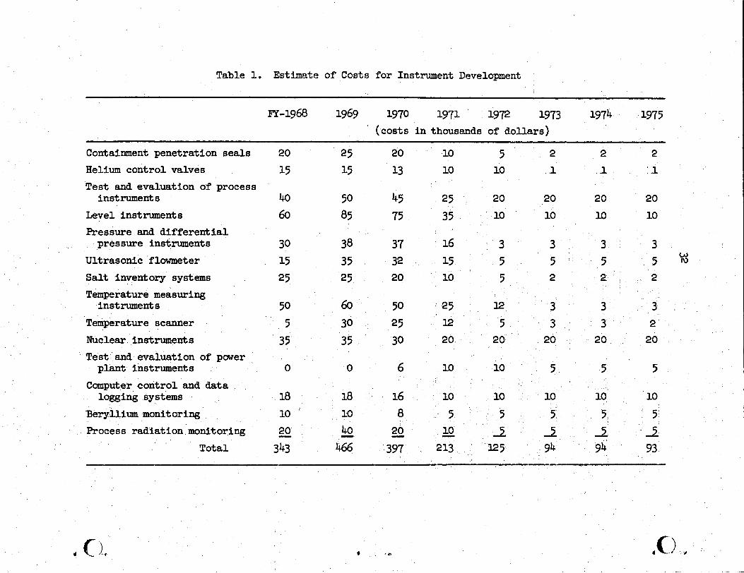
Estimate of Cost of Development Program An estimate of the cost of the development is shown in Table 1.
--
Table 1. Estimate of Costs for Instrument Development
I FY-1968 1969 1970 1971 1972 1973 1974 1975 I
(costs i n thousands of dollars)
Containment penetration seals 20 25 20 10 5 2 2 2 Helium control valves 15 15 13 10 10 .1 .1 : .1 I T e s t and evaluation of process
instruments 40 50 45 25 20 20 20 20 Level instruments 60 85 75 35 10 10 10 10 Pressure and d i f fe ren t ia l
pressure instruments 30 38 37 16 3 3 3 3 Ultrasonic flowmeter 15 35 32 15 5 5 5 5 ' u Sal t inventory systems 25 25 20 10 5 2 2 2 Temperature measuring
Temperature scanner 5 30 25 12 5 3 3 2 Nuclear instruments 35 35 30 20 20 20 20 20
w
instruments 50 60 50 25 I2 3 3 3 .
Tes t ' and evaluation of power
Computer control and data plant instruments 0 0 6 lo 10 5 5 5
logging systems 18 18 16 10 10 10 10 10
Beryllium monitoring 10 ' 10 8 5 5 5 5 ' 5 Process radiation monitoring 20 - - 40 - 20 - 10 I, 2 2 -2
T o t a l 343 466 397 213 325 94 94 93
A 33
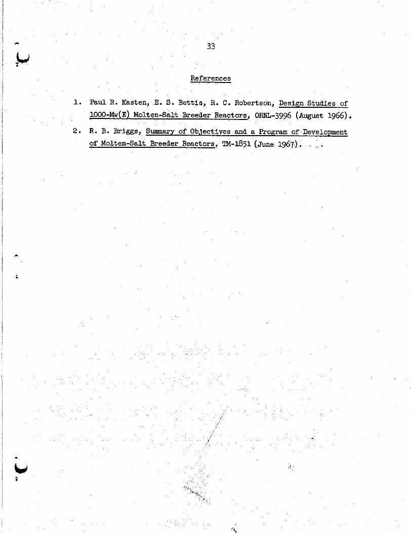
References
1, Paul R. Kasten, E. S. Bettis, R. C. Robertson, Design Studies of 1 ORNL-3996 (August 1966)
2. R. B. Briggs, Summary of Objectives and a Program of Development
of Molten-Salt Breeder Reactors, m-1851 (.Jw 1967,). - ~

.

a 35
e ,k Internal Distribution
1-50. MSRE Director's Office 99. A. Giambusso, AEC- Rm. 325, 9204-1 Washington
51. R. K. AWS 100. H. E. Goeller 52. G. M. Adamson 101. W. R. Grimes 53. R. G. Affel 102. A. G. Grindell 54. L. G. Alexander 103. R. H. Guymon 55. R. F. Apple 104. B. A. Hannaford 56. C. F. Baes 105. P. H. Harley 57. J. M. M e r 106. D. G. Harman 58. S. J. Ba l l 107. C. S. H a r r i l l 59. W. P. Barthold 108. P. N. Haubenreich 60. H. F. Bauman 109. F. A. Heddleson 61. S. E. Beall 110. P. G. Herndon 62. M. Bender 111. J. R. Hightower 63. E. S. Bettis 112. H. W. Hoffman 64. F. F, Blankenship 113. R. W. Horton 65. R. E. Blanco 114. T. L. Hudson 66. J. 0. Blomeke 115. W. H. Jordan 67. R. Blumberg 116. P. R. Kasten 68. E. G. Bohlman 117 R. ;J. Kea1 69. C. J. Borkowski 118. M. J. Kelly 70. G. E. Boyd 119. M. T. Kelley 71. M. A. Bredig 120. C. R. Kennedy 72. R. B. Briggs 121. T. W . Kerlin 73. H. R e Bronstein 122. H. T. KErr 74. G. D. Brunton 123. S. S. K i r s l i s 75. D. A. Canonico 124. D. J..Knowles . 76. S. Cantor 125. A. I. Krakoviak 77. W. L. Carter 126. J. W. Krewson 78. G. I. Cathers 127. C. E. Lamb 79. J. M . Chandler 128. J. A. Lane 80. E. L. Compere 129. W . L. Larkin, AEC-OR0 81. W. H. Cook 130. R. B. Lindauer
82-83. I). F, Cope 131. A. P. Litman 84. L. T , Corbin 132. M. I. Lundin 85. J. L, Crowle 133. R. N. Lyon 86. F. Le C d l e 134. H. G. MacPher
135. R. E. MacPherson 136. C. D. Martin
89. S. J. Ditto 137. C. E. Mathews 90. J. R. Engel 138. C. L. Matthews 91. E. P. Epler 139. R. W. McClung 9, D. E. Ferguson 140. H. E. McCoy 93. L. M. Ferris 141. H. F. McDuffie 94, A. P. Fraas 142 C. K. McGlothlan 95. H. A. Friedman 143. C. J. McHargue 96. J. H. Frye, Jr. 144-158, T. W. McIntosh, AEC- 97. C. H. Gabbard Washington h*r 98. R. B. Gallaher
*

36
Internal Distribution (continued)
159. L. E. McNeese 187. G o P. Smith 160. A. S. Meyer 188. 0. L. Smith 161. R. L. Moore 189. P. G. Smith 162. J. P. Nichols 190. W. F. Spencer 163. E. L. Nicholson 191. I. Spiewak 164. L. C. Oakes 192. R. C. Steffy 165. P. Patriarca 193. H. H. Stone 166. A. M.Perry 194. R. F. Sweek, AEC, Washington 167. H. B. Piper 195. ._ e .
168. B. E. Prince 196. R. E. Thoma 169. J. L. Redford 197. J. S. Watson 170. M. Richardson 198. S. S. Watson 171. R . C ... Robert son 199. C. F. Weaver 172. H. C. Roller 200. B. H. Webster 173. H. M. Roth, AEC-OR0 201. A. M. Weinberg 174. H. C. Savage 202. J. R. Weir 175. C. E. Schi l l ing 203. W. J. Werner 176. Dunlap Scott 204. K. W . West 177. H. E. Seagren 205. M. E. Whatley 178. W. F. Schaffer 206. J. C. White 179. J. H. Shaffer 207. L. V. Wilson ?
180-181. M. Shaw, AEC- 208. G.Young Washington 209. H. C. Young a
182. M. J. Skinner 210-211. Central Research Lib.
184. W. L. Smalley, AEC-OR0 214-223. Laboratory Records 185. A. N. Smith 224. Laboratory Records - RC 186. F. J. Smith
I 183. G. M. Slaughter 212-213. Document Reference Sect
i 4
External Distribution
225-239. 240 .
241-242. Reactor Division (ORO)
Division of Technical Information Extension (M'IE) Research and Development Director (ORO)
! - w
* I