orion high-level chloride monitor
TRANSCRIPT

Analyze • Detect • Measure • Control™
Orion High-LevelChloride Monitor
I N S T R U C T I O N M A N U A L
Pure Water ® MONITORS
1800 series
release latches to access
a
b
c
d
rifos
noglib
rifos
dome glid off
Orion 1817HL

AQUAfast, Cahn, EZ Flash, Ionalyzer, ionplus, KNIpHE, No Cal, ORION, perpHect, PerpHecT, PerpHecTion, pHISA, pHix, pHuture, Pure Water, Sage, Sensing the Future, SensorLink, ROSS Ultra, Sure-Flow, TEA Analyzer, Titrator PLUS, TURBO2 and Wine Master are registered trademarks of Thermo Electron Corporation.
1-888-pHAX-ION, A+, All in One, Aplus, AQUAsnap, AssuredAccuracy, AUTO-BAR, AUTO-CAL, AUTO DISPENSER, Auto-ID, AUTO-LOG, AUTO-READ, AUTO-STIR, Auto-Test, BOD AutoEZ, Cable-Free, CERTI-CAL, CISA, DataCOLLECT, DataPLUS, digital LogR, DirectCal, DuraProbe, Environmental Product Authority, Extra Easy/Extra Value, FAST QC, Flash Titration, Flash Titrator, GAP, GLPcal, GLPcheck, GLPdoc, ISEasy, KAP, LabConnect, LogR, Low Maintenance Triode, Minimum Stir Requirement, MSR, NISS, One-Touch, One-Touch Calibration, One-Touch Measurement, Optimum Results, Pentrode, pHuture MMS, pHuture Pentrode, pHuture Quatrode, pHuture Triode, Quatrode, QuiKcheK, rf link, ROSS, ROSS Resolution, SAOB, Smart CheK, Stacked, Stat Face, The Enhanced Lab, ThermaSense, Triode, TRIUMpH, Unbreakable pH, Universal Access are trademarks of Thermo.
Guaranteed Success and The Technical Edge are service marks of Thermo.
PerpHecT meters are protected by U.S. patent 6,168,707.
PerpHecT ROSS are protected by U.S. patent 6,168,707.
ORION Series A meters and 900A printer are protected by U.S. patents 5,108,578, 5,198,093, and German patents D334,208 and D346,753.
Sure-Flow electrodes are protected by European Patent 278,979 and Canadian Patent 1,286,720.
ionplus electrodes and Optimum Results solutions are protected by US Patent 5,830,338.
ROSS Ultra electrodes have patents pending.
ORION ORP Standard is protected by US Patent 6,350,367.
ORION Series A conductivity meters are protected by US Patent 5,872,454.
© Copyright 2003, Thermo Electron Corporation. All rights reserved. Question everything, and Analyze. Detect. Measure. Control are trademarks of Thermo Electron Corporation.
The specifications, descriptions, drawings, ordering information and part numbers within this document are subject to change without notice.
This publication supersedes all previous publications on this subject.

TABLE OF CONTENTS
I. General Information I. 1Introduction I. 1Principles of Operation I. 1Principles of Calibration I. 2Sample Requirements I. 3Description of Orion 1817HL Monitor I. 4
II. Instrument Preparation II. 1Unpacking Orion 1817HL II. 1Mounting, Plumbing and Wiring of Monitor II. 2Installation of Reagent and
Diffusion Tubing II. 3Installation of Chloride Electrode II. 3Installation of Reference Electrode II. 4Installation of ATC Probe II. 4Flow Regulation II. 4
III. Instrument Operation III. 1Description of Basic Unit Controls III. 1Start Up/ Normal Instrument Operation III. 1Initial Instrument Set-Up III. 2Use of Test Mode III. 2Error Mode III. 3Shutdown and Start-Up Procedure III. 4Flow-Off III. 4
IV. Instrument and Operation of Modules IV. 1Signal Conditioner Module IV. 1Removing Installed Module IV. 1Replacing Installed Module IV. 1Setting Module Output IV. 1Electrical Connections IV. 2Description of Signal
Conditioner Module Controls IV. 2Programming Measuring Range IV. 3Optional Alarm Module IV. 3Installation IV. 4Setting Alarm Output IV. 4Electrical Connections IV. 4Description of Alarm Module Controls IV. 5Alarm During Calibration IV. 5Alarm After Power Failure IV. 5Setting Alarms 1 and 2 IV. 5
V. Calibration V. 1Double Known Addition
Calibration Procedure V. 2Calibration at Non-standard
Concentrations Using DKA V. 4Span Check Procedure V. 4Off-line Calibration Procedure V. 5Blank Correction Procedure V. 6
VI. Instrument Maintenance VI. 1Maintenance Schedule VI. 1Weekly Maintenance VI. 1Monthly Maintenance VI. 1Bi-Monthly Maintenance VI. 2Yearly Preventive Maintenance VI. 3
VII. Troubleshooting VII. 1
VIII. Repair and Service VIII. 1
IX. Notice of Compliance IX. 1
X. Ordering Information X. 1
XI. Appendix XI. 1Resetting Computer XI. 1Mounting Dimensions XI. 2TB2 Wiring Diagram XI. 3
XII. Specifications XII. 1


I. 1
I. GENERAL INFORMATION
Figure 1Orion 1817HL Flow During Normal Calibration
flowcell
cell
flow
cell module
alve ter filter flow
terfilter
flow alve
inletvalve
inletvalve
flowcell
flowcell
cell module
cell module
cell module
flowcell
inletvalve
flow filter
ter flow
56
4789
36
3
2
11
37
19
1
18
14
temperatureprobereferenceprobesensingprobe
calibrationlevel
measuringlevel
reagentadditionsystem
drain
bypassvalve
calibrationdiverter
valve
restrictor
flowmeter
flowvalve
pressurereducing
valve
bypassfilter
inletvalve
Figure 2Block Diagram of Sample Flow
IntroductionThis manual covers operation, maintenance and troubleshooting for Orion 1817HL which incorporatesadded software features of off-line calibration andblank correction.
The Orion 1817HL High-Level Chloride Monitor contin-uously measures chloride in seawater-cooled stationsand is primarily used to control boiler blowdown. Orion1817HL Monitor measures chloride over the range 0.1to 100 ppm.
A unique system for pH adjustment eliminates theneed for expensive reagents and frequentmaintenance. Instrument calibration is quick, simple,highly reliable and accurate using a simple pipet.A temperature sensor, mounted in the measuring cell,is used for automatic temperature compensation.The installed signal conditioner offers the choicebetween linear and logarithmic concentration output.Since the 1800 Series Monitors have been designedwith few moving parts, they require little maintenanceand are extremely reliable.
Principles Of OperationFigure 1 is a block diagram of sample flow through the monitor. Figure 2 illustrates the sample flow duringnormal operation.
As shown in Figure 2 the sample enters the Series1800 Monitor and passes through inlet valve, 1,bypass filter, 2, pressure regulator, 3, flow meter, 4,and restrictor tubing, 5. The sample then passesthrough the flow cell manifold, 11, into a reagentdiffusion bottle, 14, where pH adjustment takes place.The pH adjusted sample then flows back into the flowcell manifold, 11, where air is introduced from air line,18, to ensure proper mixing and fast response. The sample then passes sensing, 8, reference, 7, and temperature, 9, probes in the top portion of the flowcell, 11. The sample then flows back through the flowcell manifold, 11, into an atmospheric drain, 19.

I. 2
The sensing electrode responds logarithmically to changes of the chloride ion concentration. Thisresponse is described by the Nernst equation:
E = E0 + 2.3 (RT/nF) • log (C/Ciso)where: E = measured electrode potential, mV
E0 = potential, when C equals C(iso), mVR = ideal gas constantT = temperature of sample, degrees Kn = valence of ionic species
(-1 for chloride ion)F = Faraday’s constantC = effective chloride ion
concentration (activity)Ciso = concentration (activity) of chloride
ion where potential E is temperatureindependent (isopotential point)
The above equation indicates that the measuredpotential varies with both temperature and theconcentration of the ion of interest. In order toeliminate error caused by fluctuations in sampletemperature, the Series 1800 Monitor’smicroprocessor constantly updates temperaturecorrections from data supplied by the ATC probe.
From the Nernst equation, the theoretical response ofa chloride ion-selective electrode to a ten-fold changein concentration at 25°C is 59.16 mV. This is referredto as the electrode slope(s). Most electrodes, however,do not exhibit a theoretical slope. Therefore, theinstrument is calibrated to determine its actual value.Two standards are used to provide informationnecessary for the microprocessor to compute theactual slope and E0 for use during sample analysis.
In order to eliminate interference from hydroxide ionswhich can become significant when measuring low levels of chloride, the Orion 1817HL Monitor adjustssample pH to below 4. This pH adjustment isaccomplished by a patented passive diffusion processwherein the sample passes through a tubing coilpresent in a reagent bottle containing aqueous acidsolution which diffuses through the tube wall andredissolves, lowering the sample pH to below 4.
Flow of sample into reservoir of flow cell is set by acombination of pressure regulator and flow restrictortube. The pressure regulator is adjusted to give anominal flow of 40 mL/min. The diverter valve on theflow cell is pulled out during normal operation, whichmaintains a sample reservoir volume of approximately20 mL. Therefore, this system’s fast response time isa result of both sample volume and flow rate. The airis for mixing the sample.
Principles Of CalibrationDouble-Known Addition (DKA)
Numbers refer to Figure 3.
Calibration procedures for an analytical instrument are important and must be performed carefully. The ORION patented calibration procedure used in the Orion 1817HL is a variation on Double KnownAddition (DKA). This method has distinct advantageswhen compared with conventional methods ofcalibration. It is fast, easy, accurate and uses areadily available pipet for calibration.
The sample reservoir, as shown in Figure 1, has twosample volumes; a normal operation volume (about 20 mL) and a calibration volume (about 100 mL).The lower volume results in fast system responsewhile on-line, and the higher volume ensures accuracyin calibration. The sample diverter valve, 12, is pushed in to fill the sample reservoir to 100 mL volume prior to calibration.
At this point the actual concentration in the sample isunknown but the instrument measures the potential(Es) and stores this value in the microprocessor. Aknown amount of Standard Solution 1 is added to thesample reservoir which increases the concentration(Cs) with a corresponding known amount (dC1). Thenew potential (E1) is measured and storedautomatically, when stability is reached. Standard 2,preferably 10 times more concentrated than Standard1, is added which again increases the concentration(dC2) in the sample reservoir. Again the new potential(E2) is measured and stored when stable. Now,we have the following three equations withthree unknowns:
Es = E0 + S log (Cs/Ciso)
E1 = E0 + S log [(Cs + dC1)/Ciso]
E2 = E0 + S log [(Cs + dC1 + dC2/Ciso]
Es, E1 and E2 have been determined during the calibration procedure. The microprocessor solvesthese three equations giving the values of S and Eo.This data is stored for use during on-line monitoring to convert the measured potential in the sample intoconcentration values either in ppm or ppb.

I. 3
When the calibration is complete, diverter valve, 12,is pulled out to lower flow cell liquid level (~100 mL),to the sample measurement level (~20 mL), and flowvalve, 36, is reopened. Allow about ten minutes forconcentrated calibration solution to be flushed fromsystem, then the Series 1800 Monitor can beginsample measurement. Typically, the calibrationprocedure takes less than 30 minutes to complete.
In addition to Double-Known Addition (DKA), Orion1817HL also allows the user the ability to performeither an off-line calibration or a blank correction.
Off-line Calibration
The off-line calibration feature of Orion 1817HL allowsthe user to adjust the monitor to values determined byalternate methods used in their laboratory, such asatomic absorption, ion chromatography and inductivelycoupled plasma. It is essentially a one-pointcalibration. To perform off-line calibration, a sample istaken from the bypass of the instrument; the samplevalue is stored in memory; the sample is analyzed byan alternate method of choice; the previously storedreading is adjusted to the lab method result; and theinstrument is then returned to the analysis mode. Theterm “off-line calibration” refers only to the fact that asample from 1817HL bypass is taken “off-line” forlaboratory analysis; in fact, no downtime isexperienced during the procedure and the instrumentremains on-line throughout.
Blank-Correction
Blank correction feature corrects deviation from astraight line Nernstian response at very low levels ofchloride. The purpose of the blank correction featureis to allow adjustment of the reading to compensate forpossible background effects due to either the reagentor other ions in the sample. It improves accuracy at thelow end of detection range.
Sample RequirementsSample inlet connection - 1/4” NPTF. If particulatematter is present in sample, prefiltration is necessary.Moderate amounts of particulates will be removed bythe 60 micron stainless steel filter located afterinlet valve.
Flow rate - 40 mL/min. nominal
Pressure - 8-100 psig. Consult Thermo ElectronCorporation for details on sample handling if pressureis outside range.
Temperature - Temperature must be between 5-40°C.
Chloride level - Chloride levels are read directly inppb or ppm, when calibrated with Standard 2 from Orion 181140 and Standard 1 fromOrion 181141.
Sample alkalinity - Sample alkalinity acidity shouldnot be more than 50 ppm CaCO3 equivalent. For higher sample alkalinity, contact the Thermo Electron’sTechnical Service Department.

I. 4
Description of Orion 1817HL Monitor Numbers in the description refer to Figure 3.
Sample inlet valve (1) - Accepts the samplestream via 1/4 inch NPTF connector. The customermust supply the sample with a pressure between 8and 100 psig, and a sample flow rate of40 mL/m in. nominal.
Bypass filter assembly (2) - 60 micron stainlesssteel filter traps particulate matter in sample stream.
Pressure regulator (3) - Adjusts flow on incomingsample stream.
Flow meter (4) - Measures sample flow rate. 40 mL/min. nominal flow is required.
Flow restrictor tubing (5) - Maintains steady sampleflow rate in conjunction with pressure regulator.
Electrolyte reservoir (6) - Provides constant flow ofelectrolyte solution through reference electrode for maximum stability.
Reference electrode (7) - Provides a constantreference potential and completes themeasurement circuit.
Chloride electrode (8) - Senses chloride ions in sample stream and produces an electrical potentialdependent on sample concentration.
ATC probe (9) - Measures sample temperature andinputs data to microprocessor for automatictemperature compensation (ATC).
Calibration port (10) - Allows introduction ofstandards to sample reservoir during calibration.
Flow cell (11) - Contains reference electrode, sampleelectrode, ATC probe and sample measurementreservoir. Air is bubbled through liquid to keepelectrodes clean as well as to mix the sample. Bothcalibration and normal measurements are made inthe flow cell.
Diverter valve (12) - Allows sample reservoir to fill to about 100 mL during calibration procedure. While sampling, reservoir is at about 20 mL.
Reagent bottle adaptor (13) - connects reagent diffusion bottle to sample stream and flowcell assembly.
Reagent diffusion bottle (14) - contains water solubleacid which lowers the sample pH to below 4.
LED display (15) - Provides digital readouts of concentration, temperature, millivolts and error codes.
Keypad (16) - Consists of five mode keys: four prompt indicator lights, two scroll keys and one key for entering data. Mode and error indicators are alsoincorporated on keypad.
On/off switch (17) - Controls all power tothe electronics.
Flow valve (36) - Used to turn off flow to flow cell during calibration.
Bypass valve (37) - Used to throttle flow inbypass system.
Air pump (38) - Used to mix standard with sample during calibration.

I. 5
Figure 3 Major Components of Low-Level Chloride Monitor
Pure Water® MONITORS
1800 series
386
release latches to access
4789
10
36
5
3
11
122
37
13
14
1
15
16
17
a
b
c
d
rifos
noglib
rifos
dome glid off

I. 6
Figure 4Details of Flow Cell Assembly
7
8
9
10
2 2
11
2 3
13
12
14
20
21
18
Legend7 reference electrode8 chloride electrode9 temperature probe10 calibration port11 flow cell assembly12 diverter valve13 bottle adapter14 diffusion bottle18 air line20 reagent safety drain21 sample drain 22 siphon tube23 thumbscrew

II. 1
II. INSTRUMENT PREPARATION
Figure 5Unpacking Orion 1817HL
Unpacking Orion 1817HLReport any obvious damage of shipping container to carrier and hold for inspection. The carrier (not Orion) is responsible for any damage incurred during shipment.
1. Open outer box. Remove foam cornersupport pieces.
2. Open inner box and remove cardboard retaining shell. Remove accessory boxes (4 pcs.) and instruction manual.
3. Unbolt the monitor from mounting board. Save all hardware for use during installation.
4. Carefully place the monitor at a convenient location.Do not pull or lift instrument by itsfluidic components.

II. 2
240V
220V
110V
100V
ground
options
AC power
common
line
jumper
Figure 6Electrical Wiring of 1800 Series Monitors
Mounting, Plumbing And WiringMounting, Plumbing and Wiring of Series 1800 Monitor
1. Select a site for instrument that allows it to bepermanently bolted in an upright position with ampleheight for atmospheric drain operation and readyaccess to both electronic controls and flow cellcalibration port. A clearance of 15” must be allowedabove the calibration port for vertical insertion ofautomatic pipet during calibration. The analyzer sitemust permit connection to sample line, a drain, anAC power supply, and any connections foroutput devices.
2. Prepare mounting holes. Carefully lift the Series1800 Monitor and bolt into place. Do not liftinstrument by pulling on any fluidic components.Be sure to use the four shoulder washers that areprovided, they will resist future corrosion.
3. Connect a waste line to a drain ofsufficient capacity.
4. Connect sample line to the 1/4-inch tube connector.It is recommended that a shutoff valve be installedat the sampling point.
5. Remove decorative panel inside the cabinet byunscrewing the four Phillips screws. Then removeprotective plug and feed AC power line throughhole. See Figure 6.
6. See Appendix for wiring diagram. Disconnect:jumper wire from TB2 terminal 7 and connect to:TB2 terminal 6 for 100V AC
5 for 115V AC4 for 220V AC3 for 240V AC
Warning: Failure to connect jumping wire tothe proper tab will permanently damagethe monitor.
7. Connect:COMMON to TB2 terminal 1 (most left)LINE to TB2 terminal 2GROUND to ground stud adjacent to terminal 1using captive type terminal at the end ofground wire.
Warning: Failure to connect chassis to a suitable ground may result in hazardous conditions. Failure to use captive type terminal could result in potential shock hazard and may jeopardize CSA approval.
8. All electrical wire feeding through the chassis mustpass through appropriate electrical fittings in orderto maintain the design integrity of the splash-proofelectronic chassis. Since different types of fittingsare required at various installations, this feedthrough is to be supplied by the user.
Warning: A grounded metal conduit isrequired for FCC compliance.
9. Replace decorative panel if no further wiringis required.
Warning: Failure to replace decorative panelcould result in potential shock hazard.

II. 3
24
11
28
23
13
25
26
14
27
Figure 7Reagent Bottle Assembly
Installation Of Reagent And Diffusion Tubing
Warning: Formic acid is hazardous. Use protective glasses and gloves. Refer to bottlelabel for precautions.
1. Remove thumbnut, 23, of bottle adaptor, 13, and slide adaptor/reagent bottle assemblyfrom instrument.
2. Unscrew cap, 24, and lift adaptor from bottle. Fit ends of diffusion tubing, 27, over bottle adaptor nipples, 25.
3. In hood (or outdoors) carefully remove cap onreagent bottle.
4. Verify there is an O-ring, 26, between the bottleadaptor and bottle. Slide diffusion tubing loopsinto reagent bottle and screw adaptor into fullreagent bottle.
NOTE: Adaptor may be rotated in bottle toallow for correct positioning.
5. Check that all three O-rings, 28, are in place on flow cell assembly face, 11. Mount bottle adaptor/reagent assembly to flow cell by sliding onto screwstud and tightening nut, 23.
Installation of Chloride Electrode1. Unpack chloride electrode (Orion 100025) and care-
fully remove protective cap. Save cap for future stor-age of electrode.
2. Insert chloride electrode into sensing hole of flowcell cap. See Figure 4. Sensing electrode is placedin the hole to the right of the divider seen in flow celland the hole closest to the electronics cabinet.
3 Connect electrode to cable marked “Sens. Elect.”
4. Wait at least one hour before calibrating analyzer.
II. 4
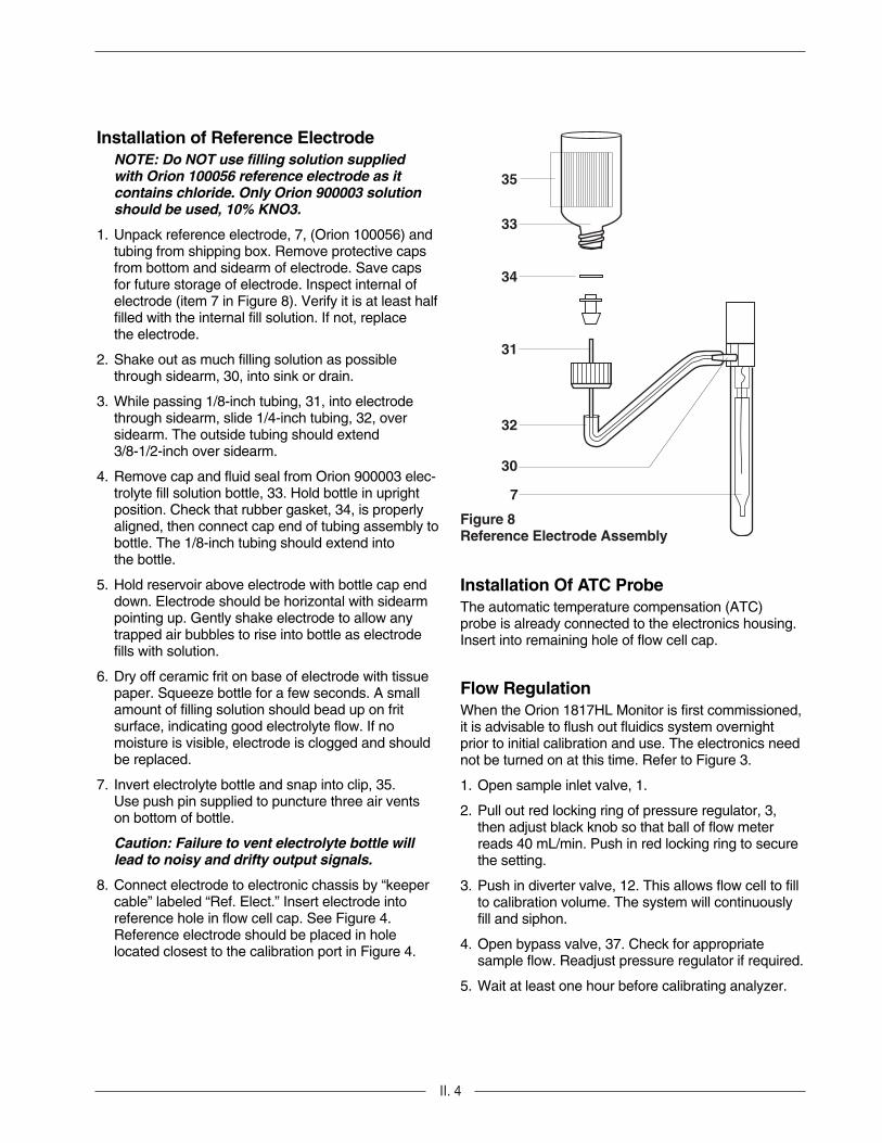
Figure 8Reference Electrode Assembly
35
33
34
31
32
30
7
Installation of Reference ElectrodeNOTE: Do NOT use filling solution suppliedwith Orion 100056 reference electrode as itcontains chloride. Only Orion 900003 solutionshould be used, 10% KNO3.
1. Unpack reference electrode, 7, (Orion 100056) andtubing from shipping box. Remove protective capsfrom bottom and sidearm of electrode. Save capsfor future storage of electrode. Inspect internal ofelectrode (item 7 in Figure 8). Verify it is at least halffilled with the internal fill solution. If not, replacethe electrode.
2. Shake out as much filling solution as possiblethrough sidearm, 30, into sink or drain.
3. While passing 1/8-inch tubing, 31, into electrodethrough sidearm, slide 1/4-inch tubing, 32, oversidearm. The outside tubing should extend 3/8-1/2-inch over sidearm.
4. Remove cap and fluid seal from Orion 900003 elec-trolyte fill solution bottle, 33. Hold bottle in uprightposition. Check that rubber gasket, 34, is properlyaligned, then connect cap end of tubing assembly tobottle. The 1/8-inch tubing should extend intothe bottle.
5. Hold reservoir above electrode with bottle cap enddown. Electrode should be horizontal with sidearmpointing up. Gently shake electrode to allow anytrapped air bubbles to rise into bottle as electrodefills with solution.
6. Dry off ceramic frit on base of electrode with tissuepaper. Squeeze bottle for a few seconds. A smallamount of filling solution should bead up on fritsurface, indicating good electrolyte flow. If nomoisture is visible, electrode is clogged and shouldbe replaced.
7. Invert electrolyte bottle and snap into clip, 35.Use push pin supplied to puncture three air ventson bottom of bottle.
Caution: Failure to vent electrolyte bottle willlead to noisy and drifty output signals.
8. Connect electrode to electronic chassis by “keepercable” labeled “Ref. Elect.” Insert electrode into reference hole in flow cell cap. See Figure 4.Reference electrode should be placed in holelocated closest to the calibration port in Figure 4.
Installation Of ATC ProbeThe automatic temperature compensation (ATC)probe is already connected to the electronics housing.Insert into remaining hole of flow cell cap.
Flow RegulationWhen the Orion 1817HL Monitor is first commissioned,it is advisable to flush out fluidics system overnightprior to initial calibration and use. The electronics neednot be turned on at this time. Refer to Figure 3.
1. Open sample inlet valve, 1.
2. Pull out red locking ring of pressure regulator, 3,then adjust black knob so that ball of flow meterreads 40 mL/min. Push in red locking ring to securethe setting.
3. Push in diverter valve, 12. This allows flow cell to fillto calibration volume. The system will continuouslyfill and siphon.
4. Open bypass valve, 37. Check for appropriate sample flow. Readjust pressure regulator if required.
5. Wait at least one hour before calibrating analyzer.

III. 1
III. INSTRUMENT OPERATION
test sample
°C ppm
mV ppb
slope error •
Eo electrode stable •
a
c
d
b
enter/done
sample test program
cal.
error
fill/flowoff
drain/flowon
addstd. 1
addstd. 2
amplifier Orion 2A01
Figure 9Front Panel Keypad
Description of Basic Unit ControlsOn/off switch - Controls power to all electronics andair pump. It is located on electronic chassis bottom andincludes an integral circuit breaker.
LCD display - Displays four-and-one-half digit pluspolarity sign used to read concentration, slope, E0,millivolts, temperature, error messages, anddiagnostic information.
Mode indicating LED - (Located to left of LCD display.) Indicates range (ppb or ppm), error codes,and electrode stable in sample mode. Displaystemperature (°C), millivolts, electrode slope, and E0on LCD in test mode.
Prompt indicating LED - Prompts the user during calibration. Four LED’s located in keypad region areused. These are: fill/flow off; add STD 1; add STD 2;drain/flow on.
and keys - Increases or decreases displayed values that can be operator-changed such as alarmlevel, analog output range, off-line calibration, andblank correction values.
Enter/done key - Enters value displayed on LCD into“permanent” memory for later use. Key also indicatesto microcomputer that a required calibration step hasbeen completed.
Sample key - Puts Series 1800 Monitor into samplemode and (re) activates any optional modules. This isalso its default mode, e.g., instrument automaticallyenters sample mode when first turned on and after calibration.
Cal key - Starts Series 1800 Monitor into calibratemode. Operator is then prompted through the stepsnecessary for calibration.
Test key - Places Series 1800 Monitor into test modewhere LCD displays temperature, millivolts, E0 andslope. Each successive push of key, steps instrumentthrough this sequence, and an LED on the left of display indicates value displayed.
Error - If error LED is lit (soft error), then pressing keycauses LCD to display an error code. Note, in the caseof “hard error,” LCD would cease to display normal output but would display error code only. Refer to ErrorCode Table.
Program key - Used to program expected dC1, dC2calibration concentration increments and flow cell volume. Also used in conjunction with Cal key foroff-line calibration and blank correction procedures.
a, b, c, and d - Keys for future expansion
Start Up/Normal Instrument Operation1. Install the Orion 1817HL Monitor according to
instructions in INSTRUMENT PREPARATION.Power supply should be wired for proper voltage and instrument suitably grounded.
2. Turn on flow at sample inlet and flush for at least one hour.
3. Power up Orion 1817HL by toggle switch on bottomof electronics case. See Figure 3.
4. Observe air bubbling through liquid in flow cell. LCD will display following information sequence:a. + 1.8.8.8.8;
b. 1817 while LEDs sequentially light; (NOTE: Mode indicating LEDs and test LED on modules are not tested during start-up sequence.)
c. Revision number of software program (e.g., -x.y-)
5. After completion of steps 1-4, the Monitor is now innormal operational mode “sample.”

III. 2
Initial Instrument Set-UpBefore first sample measurements on Orion 1817HLcan be performed, calibration concentrationincrements and flow cell volume must be programmedinto memory. See Table 1 below. P2 and P3 valuesshown are based on use of Standard 2 as found inOrion 181140 (P2) and Standard 1as found inOrion 181141 (P3).
Table 1Program Key Table
Code MeaningP0 Off-line calibration valueP1 Blank correction valueP2 Concentration increase for STD 1
addition (1.54 ppm)P3 Concentration increase for STD 2
addition (15.4 ppm)P4 Flow cell volume (95 mL ± 5)
1. Press program key five times until LCD displays P4(flow cell volume variable) for two seconds, then thecurrent value for flow cell volume will be displayed.Default value is 95 mL.
2. Change this value by using keys marked and .When display reads correct value, press enter/donekey. Volume has been stored in instrument memory.Note that programmed volume value shouldcorrespond to that stamped on side of flow cell.
3. Press program key until the LCD displays P2 (1.54ppm). Then the current value for the firstconcentration increment will be displayed. Defaultvalue is 2 ppm.
4. Change this value by using keys marked and .Press enter/done key to store appropriate value inmemory. Note P2 cannot exceed the P3 value.
5. Press program key until the LCD displays P3 (15.4 ppm) for two seconds. Then the current valuefor the second concentration increment will bedisplayed. Default value is 20 ppm.
6. Change this value by using and . Pressenter/done key to store appropriate value in memory and unit will automatically return to sample mode.
7. Battery backup of memory will maintainprogrammed variables for at least one month ifbattery is fully charged.
NOTE: When calculating P2 and P3, use aflow cell volume of 95 mL. Themicroprocessor automatically corrects theprogrammed values of P2 and P3 for theactual flow cell volume (P4).
Use of Test ModeWhen test key is pressed, the LCD displaystemperature, millivolts, slope and Eo. Every time thetest key is pressed the monitor steps through thissequence. An LED to the left of display indicatesvalue displayed.
If test mode is entered from sample mode, thensample and test LED are lit. If test mode is enteredfrom calibration mode, then calibrate and test LED arelit. Note that while LCD displays test information, theinstrument still continues normal sampling orcalibration sequence. Therefore, when sample andtest modes are pressed, signal conditioning andoptional alarm modules are active. When calibrateand test modes are pressed, calibration prompt LEDswill light as usual.
To exit test mode press sample or calibrate keyas desired. LCD will now display instantaneouscomputed concentration.
If sample key is pressed while in the calibration mode,the current calibration will abort with no data saved.

III. 3
Error ModeThe Orion 1817HL Monitor diagnoses two types oferrors which are termed “hard” and “soft.” In the eventof hard error, the analyzer cannot compute anymeaningful concentration values, error LED will be litand LCD will display an error code. The signalconditioner module will indicate zero scale and alarmswill be deactivated. Hard error must be corrected priorto resumption of normal operation (E40 and E50) by performing a complete calibration.
If error LED is active but instrument continues to display concentration, this is termed “soft” error. Softerror can affect accuracy and/or precision of displayedconcentration but not interfere with instrument’s abilityto compute sample concentration. To determine causeof soft error, press error key and LCD will display error code.
Table 2Error Codes
ErrorCode Meaning
E00 No errors
E01 Default values are used. The monitor has not been calibrated since start-up or the reset button was pushed.
E02 Sample is outside the temperature range of 5 - 40°C
E03 Combination of E01 and E02
E04 Faulty ATC probe, or related circuitry
E05 Combination of E01 and E04
E10 After calibration the new slope is outside expected range
E20 Calibration due. Last calibration performed 30 days ago. A reminder to performanother calibration.
E30 Calibration due and slope error. This indicates that the last calibration was performed at least 30 days ago and the electrode slope was out of specification at that time.
E40 Calibration overdue. It has been at least 6 weeks since the last calibration. The instrument beyond this point could be out of specification. This is a hard error. The only way to exit this error is to perform a complete DKA or off-line calibration. (Blank correction will not affect this error code.)
E50 Calibration overdue and slope error. This indicates that it has been at least 6 weeks since the last calibration and the electrode slope was out of specification at that time. Theinstrument beyond this point could be out of specification. This is a hard error. The only way to exit this error is to perform a complete DKA or off-line calibration. (Blank correction will not affect this error code.)
The most common error codes are combinations of theabove codes, but other errors may be displayed:
E12 E10 and E02
E14 E10 and E04
E21 E20 and E01
E22 E20 and E02

III. 4
Shutdown And Start-Up ProcedureThe following steps should be taken if a loss of sampleflow is expected for more than one day. Theseprocedures will prevent possible build-up of acidicreagent vapors in the analyzer.
Shutdown
1. Shut off sample flow prior to the analyzer inlet.
2. Turn off power.
3. Drain flow cell.
DANGER: Shut off power switch at base ofmonitor before beginning procedure;otherwise, the air pump will spatter acidreagent outward as bottle is removed.
WARNING: Wear rubber gloves and safetygoggles to avoid possible injury from reagentresidues in the system.
4. Remove reagent bottle and store in a well ventilatedarea such as a laboratory fume hood.
5. Carefully pull chloride and reference electrodes outof the top of the flow cell and let them hang by theirconnectors. Locate protective end cap fromreference electrode kit and place on base ofreference electrode. This will prevent the referenceelectrode from drying out.
Start-up
1. Replace the diffusion tubing if sample flow has beenoff for more than a few days. Tubing becomes brittlewith long term exposure to reagent. Use a fumehood and wear rubber gloves and safety goggles for this procedure. If age of reagent is not known,replace it and note in maintenance records. Re-install bottle on analyzer.
2. Polish chloride electrode according to instructionsfound with Orion 151713 polishing strips which areincluded with 100025 chloride electrode.
3. Restore sample flow to analyzer. If necessary,adjust pressure and flow rate through analyzer tonormal ranges.
4. Remove protective end cap from referenceelectrode. Re-install electrode on analyzerbeing careful not to disconnect reservoir tubingfrom sidearm.
5. When meter reading stabilizes (about one hour),recalibrate according to CALIBRATION.
Flow OffIf the analyzer is expected not to have flow for timeperiods of less than twenty-four (24) hours, leave theinstrument on and neglect its output.
If the time is expected to be greater than twenty-fourhours, follow Shutdown procedures.

IV. 1
IV. INSTALLATION AND OPERATION OF MODULES
1 2 3 4
Figure 10Dip Switches on Signal Conditioner Board
Signal Conditioner Module (Orion 180001)The Orion 1817HL Monitor is shipped with signal conditioner module (Orion 180001) factory installed.Read section Setting Module Output and if you need tochange the factory settings, see RemovingInstalled Module.
When factory settings are correct for your instrumentthen proceed to section Electrical Connections - SignalConditioner Module.
Removing Installed Module1. Ensure power to the Series 1800 Monitor is turned
off at power source.
2. Unscrew module keypad from the black bracketsusing the two screws on the keypad.
3. Make certain the plungers are pulled back so thatthe grommets are in a closed position.
4. Slide out module far enough to access DIP switches.
Replacing Installed Module1. Ensure power to the Series 1800 Monitor is turned
off at power source.
2. Open door of electronic assembly. Use No. 2Phillips screwdriver to remove four screws ondecorative panel.
3. Remove module keypad from shipping box.
4. Unscrew module keypad from the black bracketsusing the two screws on the keypad.
5. Make certain the plungers are pulled back so thatthe grommets are in a closed position.
6. Proceed to section Setting Module Output.
Setting Module OutputThe signal conditioner has two voltage outputs (0-5 or 0-10 volts) and two current outputs (4-20 or 0-20 mAisolated). Switches are preset by manufacturer at 0-5 volts and 4-20 mA but can be reset by DIP switch(see Figure 10) on signal conditioner printed circuitboard. When required, alter preset output valuesbefore sliding the module into the monitor, as follows(also refer to Table 3).
1. Current output, factory set at 4-20 mA. 0-20 mA isobtained when switching S1-2 into “OFF” positionand S1-3 into “ON” position.
2. Voltage output, factory set at 0-5V DC. 0-10V DC isobtained when switching S1-1 into “ON” position.
3. Slide PC Board onto instrument guide rails. Rear ofPC Board should touch backplane and plug shouldfit securely into its socket. Check that module bracket is against both rails.
4. Push plungers in.
5. Make certain flex cable is attached to keypad and toPC Board. If not, carefully slide header into socket.
Table 3 Signal Conditioner Output Modes
S1-1 S1-2 S1-3 S1-4
0-5V OFF X X X0-10V ON X X X4-20 mA X ON OFF X0-20 mA X OFF ON X
X = No effect
IV. 2
Figure 11Wiring Diagram of Signal Conditioner Module
log output
linear outputtest
setzero
set fullscale
signal output Orion 2B01
Figure 12Signal Conditioner Keypad
1 2 3 4 5 6 7 8
0 to 5V DC or0 to 10v DCOutput1K Ω Load Min.
NC NC NC NC
+ – – +
0 mA to 20 mA or4 mA to 20 mA Current Output1K Ω Load Min.
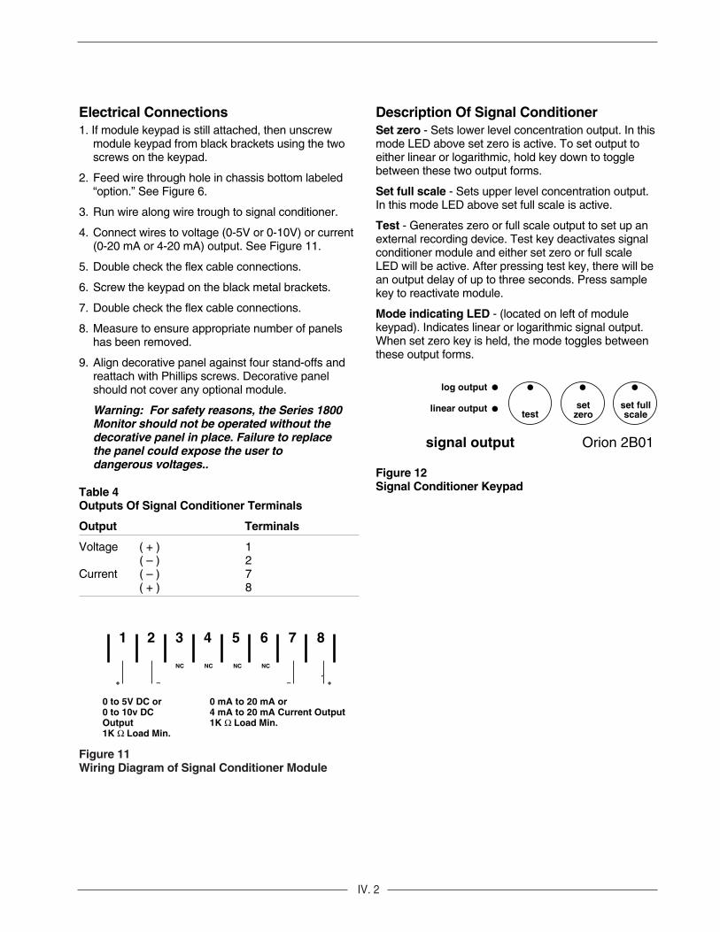
Electrical Connections1. If module keypad is still attached, then unscrew
module keypad from black brackets using the twoscrews on the keypad.
2. Feed wire through hole in chassis bottom labeled“option.” See Figure 6.
3. Run wire along wire trough to signal conditioner.
4. Connect wires to voltage (0-5V or 0-10V) or current(0-20 mA or 4-20 mA) output. See Figure 11.
5. Double check the flex cable connections.
6. Screw the keypad on the black metal brackets.
7. Double check the flex cable connections.
8. Measure to ensure appropriate number of panelshas been removed.
9. Align decorative panel against four stand-offs andreattach with Phillips screws. Decorative panelshould not cover any optional module.
Warning: For safety reasons, the Series 1800Monitor should not be operated without thedecorative panel in place. Failure to replacethe panel could expose the user todangerous voltages..
Table 4 Outputs Of Signal Conditioner Terminals
Output Terminals
Voltage ( + ) 1( – ) 2
Current ( – ) 7( + ) 8
Description Of Signal Conditioner Set zero - Sets lower level concentration output. In thismode LED above set zero is active. To set output toeither linear or logarithmic, hold key down to togglebetween these two output forms.
Set full scale - Sets upper level concentration output.In this mode LED above set full scale is active.
Test - Generates zero or full scale output to set up anexternal recording device. Test key deactivates signalconditioner module and either set zero or full scaleLED will be active. After pressing test key, there will bean output delay of up to three seconds. Press samplekey to reactivate module.
Mode indicating LED - (located on left of module keypad). Indicates linear or logarithmic signal output.When set zero key is held, the mode toggles betweenthese output forms.

IV. 3
Figure 13Jumper Connections on Alarm Module PC Board
7 8
E6 E7
E8
Programming Measuring Range1. Press set zero key. LED above set zero will
activate and LCD will display current programmedvalue. Preset default value is 100 ppb for log rangeand 100 ppb for linear range.
2. Alter value by using and keys. Lowest possible value is 100 ppb.
3. Press enter/done key when the correct valueis displayed.
4. Set upper range by pressing set full scale then follow above procedure. Preset default value is 100 ppm. Note that it is not possible to set zerovalue higher than full scale, and a range of at leasttwo decades should be used.
5. To send 0% and 100% of full scale signal to anexternal recording device, press test key on signalconditioner module. The first time causes 0% signalto be sent, the second time causes full scale signal.Remember, there may be up to a three seconddelay when test key is pressed.
6. To alternate from log to linear mode:
Press set zero key. The output mode will togglebetween log and linear, indicated by the LED. Thelog and linear zero and full scale are independentand should be set separately. Press enter/donewhen in desired mode.
Table 5Default Values - Orion 1817HL
P0 Off-line CAL Value 000P1 Blank Correction Value 000P2 (dC1) STD 1 1.54 ppmP3 (dC2) STD 2 15.4 ppmP4 (Volume) 95.0Set Zero (log) 100 ppbSet Zero (linear) 100 ppbSet Full Scale (log) 100 ppmSet Full Scale (linear) 100 ppmSet Alarm 1 100 ppbSet Alarm 2 1.00 ppmSlope - 57 mVEo -113 mV
Optional Alarm Module (Orion 180011)The Orion 1817HL alarm circuit is unique. If instrumentdetects chloride concentration is increasing at such arate that high alarm value will be reached within anhour, a warning signal is activated. This signal is a onesecond alarm every four seconds which increases infrequency as concentration approaches alarm level.Also, if absolute chloride concentration is 90% of highlevel alarm, an intermittent warning signal is activatedto alert operator that high concentration limit is beingapproached. If this feature is not desired, the “lowalarm” can be used to set external alarm. Alarms arerated at 10A, 250V.
InstallationThe optional module is mounted in the instrument inthe following manner:
1. Ensure power to the Orion 1817HL Monitor isturned off at power source.
2. Open door of electronic assembly. Use No. 2Phillips screwdriver to remove four screws on decorative panel.
3. Remove optional module keypad assembly fromshipping box.
4. Unscrew module keypad from the black bracketsusing the two screws on the keypad.
5. Make certain the plungers on the black metal frameare pulled back so that the grommets are in aclosed position.
Table 6Terminals 7 and 8 Alarms Disabled
Mode Jumper
NO E7 to E8 (factory set)NC E6 to E8

IV. 4
1 2 3 4 5 6 7 8
NC
ALARM 1Alarm contacts10A 250VAC max
Figure 14Wiring Diagram Of Alarm Module
NO
NC
NO
NC
E6E8E7
ALARM 2Alarm contacts10A 250VAC max
Disable output contactsChoose either NC or NOcontacts 10A 250VAC max
Setting Alarm OutputFor both alarms 1 and 2, NO and NC conditions areavailable simultaneously. For “alarms disabled”condition, either NO (factory set) or NC is available.To change factory setting, perform the following steps:
1. Soldered the appropriate jumper, to changebetween the NO and NC mode for an “alarmsdisabled” remote indication (terminals 7 and 8).See Figure 13.
2. Place PC Board onto instrument guide rails. Rear of PC Board should touch backplane and plugshould fit securely into its socket. Check that module bracket is against both rails. Press the two plastic plungers down to lock module in place.
3. Make certain flex cable is attached to keypad and toPC Board. If not, carefully slide header into socket.
Electrical Connections1. Feed wire through hole in chassis bottom labeled
“options” (see Figure 6).
2. Run wire along wire trough to alarm module.
3. Connect wires output as required (see Figure 14).
4. Double check the flex cable connections.
5. Screw the keypad on the black metal brackets.
6. Double check the flex cable connections.
7. Measure to ensure appropriate number of panelshave been removed.
8. Align decorative panel against four stand-offs andre-attach with Phillips screws. Decorative panelshould not cover any optional module.
WARNING: For safety reasons, the Series1800 Monitor should not operate without thedecorative panel in place. Failure to replacethe panel could expose the user todangerous voltages.
Table 6 Outputs Of Alarm Module Terminals
Outputs Terminals
Alarm 1 Comm 1NC 2NO 3
Alarm 2 Comm 4NC 5NO 6
Disable Comm 7NO/NC 8

IV. 5
Figure 15Alarm Module Keypad
alarm one
alarm two
deactivated testalarmone
alarmtwo
alarm module Orion
Description of Alarm Module ControlsSet alarm 1 - Sets alarm 1 parameter. When set alarm 1 is pressed, LED on key is active. See Table 5for default values.
Set alarm 2 - Sets alarm 2 parameter. When set alarm 2 is pressed, LED on key is active. See Table 5for default values.
Test - Activates and deactivates alarm 1 and alarm 2and deactivates relays. Test LED will be lit along withcorresponding mode key. To reactivate module, presssample key on front panel keypad.
Mode indicating LED - (located to left of keypad.)Indicates if either alarm goes off. If alarms are notactive, deactivated LED blinks; for example, duringcalibration. For both alarms, the LED indicatingactivation is on whenever concentration is above theset point. Since each alarm output has a normallyopen and normally closed position, any external alarmcan be set to go off when concentration is either aboveor below the set point.
NOTE: The corresponding LED for eitheralarms turns on when the concentrationexceeds the set point. Simultaneously, therelay closes and the NO position closes.
Alarm During CalibrationDuring calibration the alarm module is automaticallydeactivated. After the completion of calibration the Series 1800 Monitor automatically enters the samplemode, however, the alarm module remainsdeactivated. To reactivate, press sample key. Thealarm module is deactivated to avoid the highconcentration alarm that would result from the stan-dards used to calibrate.
Alarm After Power FailureAfter a power failure, the alarm module remainsdeactivated until sample key on the front panel keypad(see Figure 9) is pressed. The alarm settings are notaffected by power provided for remote indication.
Setting Alarms 1 and 2Alarm limits work on 5 decade ranges only.For example if an alarm is set to 1.0 ppb, thealarm will go off at 1.0 ppb and will continueto remain on until the 10 ppm value isreached. Anything above the 5 decade range will turn the alarm off.
1. Press set alarm 1 key. LED above set alarm 1 willactivate and LCD will display present alarm 1 value.
2. Change displayed value by use of and keys.
3. Press enter/done key when correct value isdisplayed. Alarm 1 value is now set.
4. Press set alarm 2 key. LED above set alarm 2 willactivate and LCD will display present alarm 2 value.
5. Change displayed value by use of and keys.
6. Press enter/done key when correct value is displayed. Alarm 2 value is now set.
7. If an external alarm circuit is to be tested, press testkey. The first press of the test key deactivates bothalarms, second press activates alarm 1, and thirdpress activates alarm 2. Press sample key to exittest mode.


V. 1
V. CALIBRATION
Figure 16Flow Diagram During Calibration
Figure 17Pipet Inserted Into Calibration Port
Requires use of 0.5 mL pipettor.
Maximum system accuracy is ensured through a fast,easy, and accurate calibration performed in theexpected sample range. This calibration procedureuses equipment listed under ORDERINGINFORMATION. If operator is not familiar with pipetequipment and technique, review guide in calibrationkit. Proper pipetting technique is crucial to calibration.See Figure 16 for flow diagram during calibration.
Before performing Double-Known Addition be sure to:
1. Perform Monthly Maintenance procedureincluding polishing of electrode. Wait at least onehour after changing reagent or polishing electrode.
2. Check to ensure calibration concentrationincrements (P2, P3) and flow cell volume (P4) areproperly programmed. These three values will besequentially displayed with each successive pressof program key.
3. Check that present background concentration isequal or less than P2; if not, calibration can still beperformed with a loss in accuracy as long asbackground concentration is not significantlylarger. Accuracy can be attained if alternatestandards are employed.
4a. If signal conditioner module is attached, outputcan be deactivated during calibration procedure bypressing test key on signal conditioner keypad.
4b. If optional alarm module is attached it will automatically go into deactivate mode upon entering calibration mode. It will not automaticallygo into activate mode after calibration. It will notautomatically go into activate mode aftercalibration. The sample key must be pressedto reactivate.

V. 2
Double Known Addition Calibration
Action Orion 1811 Monitor Response
1. Polish chloride electrode according to procedure in Calibration response times are shorter if chloride polishing package strips. electrode has been recently polished.
2. Push in diverter valve on flow cell. Reservoir begins to fill. See Figures 1 and 2. Theliquid level will rise above siphon inlet then begin to drop. Typical time about five minutes.
Typically, new siphon tubes are dry and require wettingto function optimally. Should siphoning action not begin as expected, wait until flow cell reservoir is nearly full but before the liquid level overflows the crook tube. Quickly push the diverter valve in and out until siphoning action begins.
3. Wait approximately one hour before calibration. This waiting period ensures best possible calibration accuracy.
4. Open calibration port of flow cell cap. See Figure 17 or Figure 4.
5. Press calibrate key. Wait for fill/flow off LED to light. Within three seconds fill/flow off LED will light.
6. Wait until the liquid level begins to drop. It is mandatory that inlet valve be closed while the IMMEDIATELY close flow valve. Figure 3, No. 36. liquid drops to ensure the correct calibration volume.
Open inlet and repeat step 6 if in doubt.
7. Wait until siphoning stops. Press enter/done key. Fill/flow off LED will go off. The analyzer now monitors the electrode potential and its value is automatically stored as soon as stability is reached. add STD 1 LED will light. LCDwill display expected P2 value. Typical time 1-5 minutes.*
8. Wait for add Std 1 LED to light.
9. Pipet STD 1 (use Standard 2 from181140) into The analyzer now monitors the electrode potential and reservoir with automatic pipet. Press enter/done its value is automatically stored as soon as stability is key. Remove and discard pipet tip. reached. Add Std 2 LED will light. LCD will display
expected P3 value. Typical time 1-5 minutes.*
10. Wait for add Std 2 LED to light.
V. 3
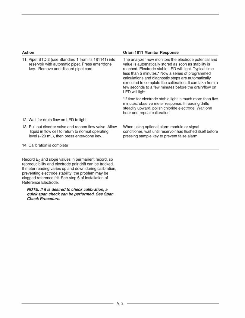
Action Orion 1811 Monitor Response
11. Pipet STD 2 (use Standard 1 from its 181141) into The analyzer now monitors the electrode potential and reservoir with automatic pipet. Press enter/done value is automatically stored as soon as stability is key. Remove and discard pipet card. reached. Electrode stable LED will light. Typical time
less than 5 minutes.* Now a series of programmed calculations and diagnostic steps are automatically executed to complete the calibration. It can take from afew seconds to a few minutes before the drain/flow on LED will light.
*If time for electrode stable light is much more than five minutes, observe meter response. If reading drifts steadily upward, polish chloride electrode. Wait one hour and repeat calibration.
12. Wait for drain flow on LED to light.
13. Pull out diverter valve and reopen flow valve. Allow When using optional alarm module or signal liquid in flow cell to return to normal operating conditioner, wait until reservoir has flushed itself beforelevel (~20 mL), then press enter/done key. pressing sample key to prevent false alarm.
14. Calibration is complete
Record E0 and slope values in permanent record, so reproducibility and electrode pair drift can be tracked. If meter reading varies up and down during calibration, preventing electrode stability, the problem may be clogged reference frit. See step 6 of Installation of Reference Electrode.
NOTE: If it is desired to check calibration, aquick span check can be performed. See Span Check Procedure.
V. 4
Calibration At Non-StandardConcentrations Using DKAThe Orion 1817HL Monitor has been preset to accommodate 0.5 mL additions of ORION STD 2 (from 181140) and STD 1 (from 181141) and flow cellvolume of 95 mL. The operator has programmed theactual flow cell volume (P4) in the analyzer duringstart-up procedure.
The operator has the option to use alternate standardsby changing the P2 (dC1) STD 1 and P3(dC2) STD 2values of the instrument program. For maximumaccuracy, P2 should be at least twice the normalconcentration in the sample, while P3 should be aboutten times P2. P2 should not be less than 10 ppb.
The calculations to determine concentrations of STD1 and 2 to obtain the correct concentration changes (P2 and P3) are as follows:
Standard 1 = P2 (Vc +Va)/(Va)Standard 2 = P3 (Vc + 2Va)/(Va)
P2 = concentration change due to first addition (dC1)
P3 = concentration change due to secondaddition (dC2)
Vc = uncorrected volume of 95 mL (volume correctionfor actual flow cell volume done automatically)
Va = volume of addition, being 0.1 mL (other volumescause incorrect volume corrections)
Substitution of Vc and Va with their values results into:
Standard 1 = 951 P2Standard 2 = 952 P3
Span Check Procedure The Series 1800 Monitor remains in sample mode during the entire procedure. Optional modules can be deactivated by pressing test key on the module keypad. Note: Either Standard 2 from 181140 orStandard 1 from 181141 can be used for span check.
1. Fill flow cell to calibration level.
2. Note concentration displayed when electrodestable LED activates (Ci).
3. Add STANDARD with concentration C2.
4. When electrode stable LED reactivates, note concentration (Cs).
5. The noted value should be within ±10% of the calculated value according to:
Cs = (Ci x Vo + C2 x Va)/Vt where:Vo = actual volume of flow cell in mLC2 = concentration of STANDARD Va = added volume of STANDARD in mLVt = (Vo + Va) in mL
6. If reading is outside the ±10% limit, pull out the diverter valve draining the flow cell and repeat steps 1-5. If results are still outside the ±10% limit,recalibrate the instrument.

V. 5
Off-Line Calibration ProcedureThe off-line calibration feature is simply a one-pointcalibration, using an alternate method value for P0. The term “off-line calibration” refers only to the fact that a sample from 1817HL bypass is taken “off-line” forlaboratory analysis; in fact, no downtime is experiencedand the instrument remains on-line throughoutthe procedure.
Action Orion 1811 Monitor Response
1. Take grab sample from bypass of 1817HL (Figure 3, No. 37). Make certain unit is in sample mode.
2. Press calibrate key. Wait for fill/flow off LED Cal LED lights. Within three seconds fill/flow off LED to light. will light.
3. Press program key. Program LED lights. Activating the program key allows current mV values and concentration to be simultaneously stored in both P0 and P1. For purposes of off-line calibration, only P0 is used. The unit returns automatically to sample mode. Program LED remains on indicating an off-line calibration has been initiated.
4. User returns with grab sample analysis value. There is no time limit on this step; program LED remains on.
5. Press program key. Allows user to view previously stored value of P0.
6. Press scroll keys, if required, to adjust reading to There are no set limits for off-line calibration value.the grab sample analysis value.
7. Press enter/done key. The monitor will remain in program mode with thecorrectly adjusted P0 value from step 6 displayed, while internally the Eo is calculated. When calculationsare completed, the monitor will return to sample mode.
Once the enter/done key is pressed to accept the adjusted value for the off-line calibration, P0 and P1 can no longer be edited and if blank correction was previously used, P1 will display the last blank value.

V. 6
Blank Correction Procedure
Blank correction procedure is similar to Off-line Calibration Procedure. See below for step-by-step instructions. Blank correction calculates the difference(in ppb) between the “stored” value of P1 and the“scrolled” value of P1 and then, adds (or subtracts) thedifference. Note that P1 can be scrolled a maximum of ±100 ppb from the saved value.
Action Orion 1811 Monitor Response
1. Take grab sample from bypass of 1817HL (Figure 3, No. 37). Make certain unit is in sample mode.
2. Press calibrate key. Wait for fill/flow off LED to light. Within three seconds fill/flow off LED will light
3. Press program key. Program LED lights. Activating the program key allows current mV values and concentration to be simultaneously stored in both P0 and P1. For purposesof blank correction, only P1 is used. The unit returns automatically to sample mode. Program LED remains on indicating a blank correction has been initiated.
4. User returns with grab sample analysis value. There is no time limit on this step; program LED remains on.
5. Press program key TWICE. Allows user to view previously stored value of P1.
6. Press scroll keys, if required, to adjust reading to P1 is only able to be scrolled a maximum of ± 1.0 ppb the grab sample analysis value. from the previously stored value.
7. Press enter/done key. After enter/done has been pressed, the difference in ppb between the stored value and the scrolled value is calculated, and the difference is added or subtracted from the reading.
The 1817HL will not allow negative concentrations to be indicated by the blank.
8. Optional: Press program key to to view P1. The value displayed is the delta for blank correction. Neither P0 nor P1 can be scrolled at this point.
In case of computer reset, neither P0 nor P1 can be scrolled until an off-line calibration or blank correction has been initiated.
NOTE: It is possible to activate both off-line calibration and blank correction by performing an off-line calibration procedure before blank correction procedure. If blank correction is performed before an off-line calibration, erroneous readings could result. If consecutive blank corrections are performed, the delta value being displayed will be the cumulative delta of the consecutive blank corrections.

VI. 1
VI. INSTRUMENT MAINTENANCE
Maintenance ScheduleThe Orion 1817HL Monitor is designed for simplemaintenance. Follow instructions in this section toensure proper operation of your instrument. Table 8outlines our recommended maintenance schedule.
IMPORTANT: To ensure proper maintenanceand good analyzer performance, a service logbook should be kept. Record date and type ofmaintenance done. Mark and date fluid levelsof reagent and reference reservoir and datewhen replaced. Tag each electrode cable withinstallation date of electrode. This systemhas proven to be successful by ThermoElectron’s Service Department, and is espe-cially useful to plants who rotateinstrument operators.
Thermo’s Service Department provides a periodic checkout, calibration, and operator training service on site to certify analyzer performance to publishedspecifications. This service can be tailored to fit individual customer needs. If interested, please contact Thermo Electron’s Service toll-freeat 1-800-225-1480.
Table 8Recommended Maintenance Schedule
Frequency Operation
Weekly Check flow rateVisual inspectionSpan check
Monthly Polish sensing electrodeCalibrateCheck reference electrode filling solution and refill if necessaryClean or replace filter element
2 Months Replace reagent, diffusion tubing, and flow manifold face O-rings
12 Months Replace reference electrodeReplace chloride electrodeReplace O-rings and valve sealsReplace restrictor tubing
Weekly Maintenance1. Check that sample flow rate is between 35 and
45 mL/min. To alter flow rate, pull out red lockingring of pressure regulator, then rotate black knob toincrease (clockwise) or decrease (counterclockwise)sample flow. Push in red locking ring to set rate.
2. Inspect unit for leakage. Diffusion tubing leakage isindicated by a rise in level of reagent.
3. Check that there are no error indications and displayed concentration is reasonable.
4. Check that reference electrolyte solution is adequate. (One bottle lasts up to several months.)
5. Perform Span Check to determine electrode driftbetween monthly calibration periods. Refer toCalibration for span check procedure.
Monthly MaintenancePolish Chloride Electrode
Using Orion 151713
1. Chloride electrode should be polished according toinstructions on Polishing Strips (Orion 151713).
Calibration
Refer to Calibration for step-by-stepcalibration procedure.
Replacement of Reference Electrode FillingSolution Using Orion 150072
Refer to Figure 8.
Discard 181073 KCl fill solution which comes with100056 reference electrode. Fill solutions containingchloride cannot be used with 1817HL monitor. Orion900003 fill solution must be used with 1817HL.
Filling solution is meant to be a two month supply.Therefore, if reservoir is less than half full, replacesolution as follows:
1. Remove spent electrolyte bottle from clip. Unscrewcap and discard bottle.
2. Remove cap and seal from new electrolyte fillsolution. Check that rubber gasket is properlyaligned, then connect cap/tubing assembly tobottle. The 1/8” tubing should extend into the bottle.
3. Invert electrolyte bottle and snap into clip.
4. Use push pin to puncture three air vents in bottomof bottle.
VI. 2
manifoldface
duck billvalve
O-rings (3)
valve stemO-rings (2)
retaining ring
valve stem
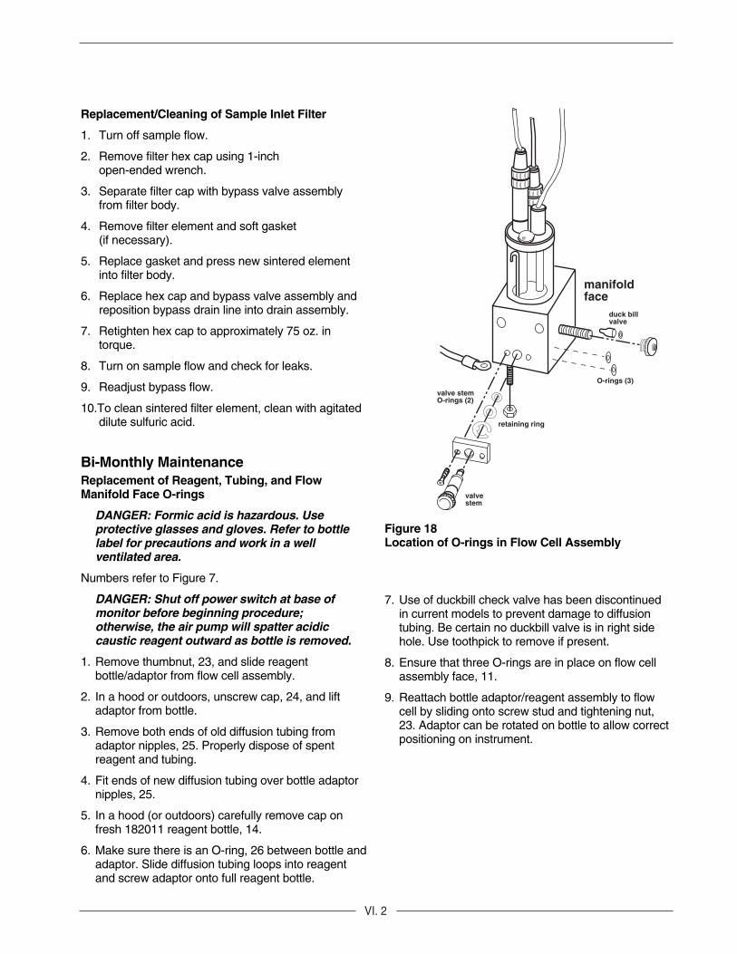
Figure 18Location of O-rings in Flow Cell Assembly
7. Use of duckbill check valve has been discontinuedin current models to prevent damage to diffusiontubing. Be certain no duckbill valve is in right sidehole. Use toothpick to remove if present.
8. Ensure that three O-rings are in place on flow cellassembly face, 11.
9. Reattach bottle adaptor/reagent assembly to flowcell by sliding onto screw stud and tightening nut,23. Adaptor can be rotated on bottle to allow correctpositioning on instrument.
Replacement/Cleaning of Sample Inlet Filter
1. Turn off sample flow.
2. Remove filter hex cap using 1-inchopen-ended wrench.
3. Separate filter cap with bypass valve assemblyfrom filter body.
4. Remove filter element and soft gasket(if necessary).
5. Replace gasket and press new sintered elementinto filter body.
6. Replace hex cap and bypass valve assembly andreposition bypass drain line into drain assembly.
7. Retighten hex cap to approximately 75 oz. intorque.
8. Turn on sample flow and check for leaks.
9. Readjust bypass flow.
10.To clean sintered filter element, clean with agitateddilute sulfuric acid.
Bi-Monthly MaintenanceReplacement of Reagent, Tubing, and FlowManifold Face O-rings
DANGER: Formic acid is hazardous. Use protective glasses and gloves. Refer to bottlelabel for precautions and work in a wellventilated area.
Numbers refer to Figure 7.
DANGER: Shut off power switch at base ofmonitor before beginning procedure;otherwise, the air pump will spatter acidiccaustic reagent outward as bottle is removed.
1. Remove thumbnut, 23, and slide reagentbottle/adaptor from flow cell assembly.
2. In a hood or outdoors, unscrew cap, 24, and liftadaptor from bottle.
3. Remove both ends of old diffusion tubing fromadaptor nipples, 25. Properly dispose of spentreagent and tubing.
4. Fit ends of new diffusion tubing over bottle adaptornipples, 25.
5. In a hood (or outdoors) carefully remove cap onfresh 182011 reagent bottle, 14.
6. Make sure there is an O-ring, 26 between bottle andadaptor. Slide diffusion tubing loops into reagentand screw adaptor onto full reagent bottle.

VI. 3
restrictoradapter
restrictortube assembly
clamp
fitting
flow meter O-ring
to flow cellmanifold
Figure 19Restrictor Tubing Assembly
Yearly Preventive MaintenanceReplace Reference Electrode (Orion 100056)
1. See Instrument Preparation for step-by-step instructions.
Replace Sensing Electrode (Orion 100025)
1. See Instrument Preparation forstep-by-step instructions.
Replace O-rings (refer to Figure 18)
Replace Valve Stem O-rings (2)
1. Remove two screws that hold valve stem assemblyin place.
2. Gently pull on valve stem to remove.
3. Slide off two old O-rings and replace. It is not necessary to remove retaining ring.
4. Place assembly back into manifold block and tighten screws.
NOTE: Do not use O-ring grease.
Manifold Face O-rings
1. Remove reagent bottle assembly.
2. Remove three O-rings from face of flow cell manifold.
3. Insert new O-rings.
Reagent Bottle Assembly O-Ring
1. When reagent bottle is removed, replace O-ringbetween bottle and adaptor.
Replacement of Restrictor Tubing
1. Close sample inlet valve.
2. Loosen fitting connector cap on top of flow meterassembly and pull out restrictor adaptor andrestrictor tube assembly.
3. Unscrew restrictor from flow cell manifold inlet byturning complete restrictor tubing assemblycounter-clockwise.
4. To simplify removal and installation of restrictor tubing, loosen the two (2) Phillips head screws holding the flow cell to the rear panel. Carefullypull the flow cell assembly away from the rear panel(about 1 to 1-1/2”).
5. Replace old restrictor assembly with new assemblybeing careful not to cross thread flow cell manifoldinlet. Tighten Phillips head screws holding flow cellto rear panel in step 5.
6. Push adaptor into fitting connector on top of flowmeter assembly and hand tighten.
7. Turn on sample inlet valve and check for leaks.Hand tighten where necessary.
Individual components can be ordered separately.See ORDERING INFORMATION for part numbers.

VII. 1
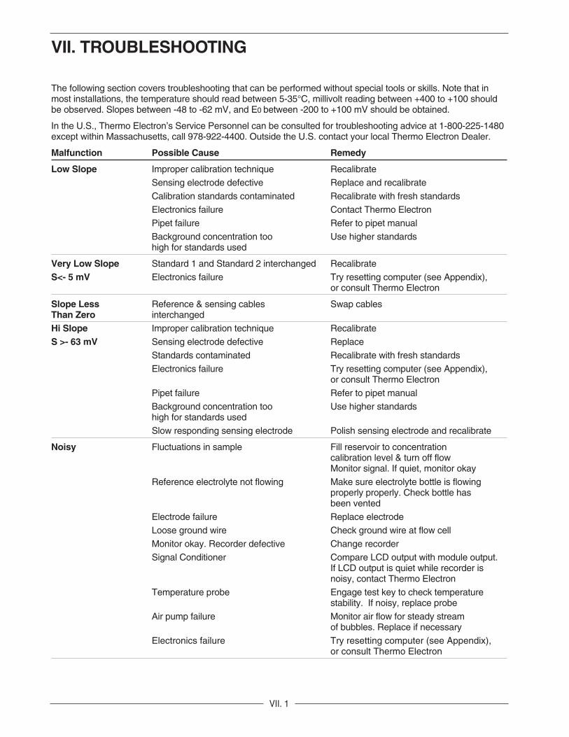
VII. TROUBLESHOOTING
The following section covers troubleshooting that can be performed without special tools or skills. Note that inmost installations, the temperature should read between 5-35°C, millivolt reading between +400 to +100 shouldbe observed. Slopes between -48 to -62 mV, and E0 between -200 to +100 mV should be obtained.
In the U.S., Thermo Electron’s Service Personnel can be consulted for troubleshooting advice at 1-800-225-1480except within Massachusetts, call 978-922-4400. Outside the U.S. contact your local Thermo Electron Dealer.
Malfunction Possible Cause Remedy
Low Slope Improper calibration technique Recalibrate
Sensing electrode defective Replace and recalibrate
Calibration standards contaminated Recalibrate with fresh standards
Electronics failure Contact Thermo Electron
Pipet failure Refer to pipet manual
Background concentration too Use higher standardshigh for standards used
Very Low Slope Standard 1 and Standard 2 interchanged Recalibrate
S<- 5 mV Electronics failure Try resetting computer (see Appendix), or consult Thermo Electron
Slope Less Reference & sensing cables Swap cablesThan Zero interchanged
Hi Slope Improper calibration technique Recalibrate
S >- 63 mV Sensing electrode defective Replace
Standards contaminated Recalibrate with fresh standards
Electronics failure Try resetting computer (see Appendix), or consult Thermo Electron
Pipet failure Refer to pipet manual
Background concentration too Use higher standardshigh for standards used
Slow responding sensing electrode Polish sensing electrode and recalibrate
Noisy Fluctuations in sample Fill reservoir to concentration calibration level & turn off flow Monitor signal. If quiet, monitor okay
Reference electrolyte not flowing Make sure electrolyte bottle is flowingproperly properly. Check bottle has been vented
Electrode failure Replace electrode
Loose ground wire Check ground wire at flow cell
Monitor okay. Recorder defective Change recorder
Signal Conditioner Compare LCD output with module output. If LCD output is quiet while recorder is noisy, contact Thermo Electron
Temperature probe Engage test key to check temperature stability. If noisy, replace probe
Air pump failure Monitor air flow for steady stream of bubbles. Replace if necessary
Electronics failure Try resetting computer (see Appendix), or consult Thermo Electron

VII. 2
Malfunction Possible Cause Remedy
Excessive Drift Sample concentration varying Perform span check. If checks out, monitor okay
Loose ground Check ground wire connection at flow cell. Tighten if necessary
Reference electrolyte not draining Make sure electrolyte bottle is properly vented - check tubing to electrode
for obstruction
Reference electrode Replace reference electrode
Chloride electrode Replace electrode
Temperature probe Engage test key to check temperature stability. If noisy, replace probe
Burst diffusion tubing Monitor liquid level in reagent bottle. If liquidlevel rises, replace reagent & diffusion tubing. Tubing connector mayneed replacement
Electronics failure Try resetting computer (see Appendix), or consult Thermo Electron
Low Flow Rate Sample pressure below 8 psi Check sample pressure. If less than
8 psi, increase
Pressure regulator set too low Increase pressure by pulling on red locking ring and turning black knob clockwise
Bypass filter clogged Replace or clean filter
Restrictor tubing crimped or clogged Replace restrictor tubing
No Air Bubbles Air line crimped or disconnected Check air line. Repair as required
Pump failure Replace if necessary
Does Not Calibrate Contaminated standards, pipet or Use new standard solutions.Properly pipet tips Replace tip. Refer to pipet manual for
proper pipetting technique
Reagent spent Replace reagent
Pipet failure Refer to pipet manual
Flow cell contaminated Rinse flow cell with DI water. Flush flow cellovernight with flow on at calibration liquid level
Electrode failure Replace one or both electrodes
Temperature probe failure Replace or consult Thermo Electron
Electronics failure Try resetting computer (see Appendix), or consult Thermo Electron
During calibration add STD 1 Flow cell contaminated. Rinse LED does not light and flow cell with DI water. Flush flow concentration increases cell overnight at calibration liquid level.
Spike system by adding 0.5 mL of STD 1 while cell is filling.See calibration instructions

VII. 3
Malfunction Possible Cause Remedy
High Readings Monitor out of calibration Recalibrate
Monitor flow cell contaminated Rinse flow cell with DI water. Flush flow cellovernight with flow on at calibration liquid level
Inlet filter just replaced Flush one hour
If off-line calibration performed, verify accuracy of alternate method value
Default Power loss while back-up battery Allow battery to charge was not fully charged overnight. Recalibrate and reprogram
Battery failure Consult Thermo Electron
Electronics failure Try resetting computer (see Appendix), or consult Thermo Electron
Incorrect Keyboard Computer glitch Turn main power off and on. RecalibrateDisplay
Electronics failure Try resetting computer (see Appendix), or consult Thermo Electron
Low Readings Instrument okay. Sample very pure Perform Span Check Procedure. If passes, instrument okay with sample being very pure
Electronics failure Try resetting computer (see Appendix), or consult Thermo Electron
If off-line calibration performed, verify accuracy of alternate method value
Reads 1.... Electrode cable failure, or not Loosen four screws holding connected to computer board main keypad. Check that cables
are attached securely
Electronics failure Try resetting computer (see Appendix), or consult Thermo Electron


VIII. 1
VIII. REPAIR AND SERVICE
For the most current warranty information, visitwww.thermo.com.
After troubleshooting all components of your measure-ment system, contact The Technical Edge
SMfor Orion
products. Within the United States call 1.800.225.1480,outside the United States call 978.232.6000 or fax978.232.6031. In Europe, the Middle East and Africa,contact your local authorized dealer. For the most cur-rent contact information, visit www.thermo.com.


IX. 1
IX. NOTICE OF COMPLIANCE
This meter may generate radio frequency energy andif not installed and used properly, that is, in strictaccordance with the manufacturer’s instructions, maycause interference to radio and television reception. Ithas been type-tested and found to comply with thelimits for a Class B computing device in accordancewith specifications in Subpart J of Part 15 of FCCRules, which are designed to provide reasonableprotection against such interference in a residentialinstallation. However, there is no guarantee thatinterference will not occur in a particular installation.If the meter does cause interference to radio ortelevision reception, which can be determined byturning the unit off and on, the user is encouraged totry to correct the interference by one or more of thefollowing measures:
• Reorient the receiving antenna,
• Relocate the meter with respect to the receiver
• Move the meter away from the receiver
• Plug the meter into a different outlet so that the meter and receiver are on different branch circuits
If necessary, the user should consult the dealer or anexperienced radio/television technician for additionalsuggestions. The user may find the following bookletprepared by the Federal Communications Commissionhelpful:
“How to Identify and Resolve Radio-TV InterferenceProblems.”
This booklet is available from the U.S. GovernmentPrinting Office, Washington, D.C. 20402
Stock No. 004-000-00345-4.
This digital apparatus does not exceed the Class Alimits for radio noise emissions from digital apparatusset out in the Radio Interference Regulations of theCanadian Department of Communications.
“Le présent appareil numérique n’ émet pas de bruitsradioélectriques dépassant les limites applicables auxappareils numériques (de la class A) prescrites dans leRèglement sur le brouillage radioélectrique édicté parle ministère des Communications du Canada.”


X. 1
X. ORDERING INFORMATION
Orion Description
1817HL Microprocessor High-Level Chloride Analyzer complete with chloride electrode (100025), reference electrode (100056), temperature sensor (181127), standard solutions kit (181140) and (181141); internal fill solution (900003) for use with 100056,signal output module (180001), and instruction manual. 4-20 or 0-20 mAmps, isolated maximum load 1000 ohms, and 0-5 or 0-10V AC, isolated minimum load 1000 ohms. Wired for100/115/220/240V AC, 50/60 Hz.
100025 Chloride electrode for use with detachable cable
100056 Reference electrode for use with detachable cable
900003 Reference electrode internal filling solution, five 2-oz. bottles. For use with 100056
181121 O-ring kits, pack of five sets
182022 Diffusion bottle adaptor/cap assembly
181123 Pressure regulator
503922-A01 Flow meter assembly (181124)
181125 Restrictor tube assembly
181127 Temperature sensor
207808-A01 Flow cell assembly, excluding electrodes, temperature probe and diffusion bottle (181128)
181170 Inlet filters, stainless steel, 60 micron filters with gaskets, pack of 2
181171 Filter gaskets (for use with 181170), pack of 2
212732-A01 Shutoff valve (181172)
181173 Air pump assembly
180001 Signal Conditioner

X. 2
Consumables
Orion Description
182011* Acid Reagent for 60 days operation (one liter bottle) with one 2 foot length thin-walled tubing and O-rings
181060 Diffusion tubing
181140 Standard solutions kit. Discard Standard 1 and use ONLY Standard 2 with 1817HL
181141 High-level standard solutions kit. Discard Standard 2 and use only Standard 1 with 1817HL
204817-001 Pipet, 0.5 mL
204816-001 Pipet tips, set of 100
* Hazardous material.
Orion Description
Options
180011 Alarm module: two adjustable alarms
180029 Electronic Test Kit
Spare Parts
Orion Description
224418-AO1 PMA Board & E-PROM for off-line cal and blank correction
210582-A01 Stem valve assembly
703275-A01 Electrode cable
802062-A01 Power board
503951-A01 Keypad with driver board
703278-A01 Power supply to PMA cable
802095-001 Ribbon cable
204743-001 Power switch

XI. APPENDIX
XI. 1
Resetting ComputerResetting the computer will clear any erroneous valuesthat have been stored in memory. Resetting will alsoset all values back to the default values, i.e., slopeequals -57 mV and Eo equals -113 mV. The defaultvalues can be found in Table 5. Reprogram P2, P3and P4 after resetting if required.
WARNING: While low voltage is present onthe computer board and in computer area,the following procedure should be performedby qualified personnel only.
Check test values according to the procedure in Useof Test Mode. Temperature should read between 5-40°C, millivolts typically are between +400 mV and+100 mV, slope should be between -48 to -62 mV,and Eo should be in the -200 to +100 mV range. If thereading is 1......, or always stays at the lowestpossible reading, such as 0.1 ppm on the 1817HL, itis overrange.
If the keypad always displays the same reading and/ordoes not respond to touch commands by the user, theanalyzer is “locked up.”
If an overrange reading is noted, or if the analyzer is“locked up,” the PMA (main computer) board should bereset according to the following procedure.
Sometimes what appears to be an electronics problemreally isn’t; instead the analyzer is merely “confused.”This type of problem often shows up during thecalibration procedure.
For example, if a calibration is attempted with incorrectstandards or defective electrodes, the electronics willattempt to determine slope and Eo and may end upwith abnormal values; i.e., Eo = +150 and slope = 1.0.Even if standards or electrodes are replaced with goodones, calibration may still be impossible. Reset thePMA board according to the following steps:
1. Turn power to analyzer OFF.
2. Loosen the four screws holding keypad and let it hang loose by its ribbon cable.
3. Reset button is located on left rear of PMA board directly behind keypad. The electrode cables connect to this board. Locate position of reset button using a flashlight. Turn power on.
4. Reset by holding button down for two seconds using a non-conductive tool such as the eraser end of a pencil.
5. Release button, then immediately lift up keypad. Display lights should go through normal power up sequence.
6. Re-install keypad.
By resetting the electronics, any erroneous values arereplaced by values of -57 mV for slope and -113 mVfor Eo and are put into memory. P4, P2 and P3 valueswill change to 95 mL, 2 ppm and 20 ppm and shouldbe reset if necessary. If no other problems exist withthe analyzer, recalibrate according to Calibration.
After calibration, the test values should be in properrange and no error lights visible. If not, checkTroubleshooting Guide.
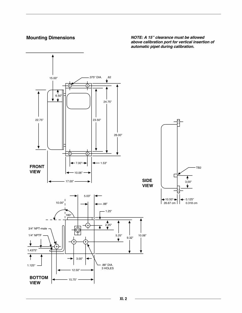
TB2
3.00"
6.50"
.62.375" DIA.
0.125"0.318 cm
10.50"
17.00"
15.00"
22.75" 23.50"
26.00"
24.75"
1.53"
.88"
1.25"
2.25"
.88" DIA.3 HOLES
5.25" 10.06"9.32"
10.06"
7.00"
5.03"
3.00"
12.50"
1.4375"
1.125"
3/4" NPT-male
1/4" NPTF
15.75"
10.00"
180°
26.67 cm
SIDE VIEW
FRONTVIEW
BOTTOMVIEW
NOTE: A 15” clearance must be allowedabove calibration port for vertical insertion ofautomatic pipet during calibration.
Mounting Dimensions
XI. 2

1 2 3
1
TB1
J1
+ + +2 3
4
13CB1
24
5 6 7 8
240V
220V
115V
100V
CO
MM
240V
220V
115V
100V
CO
MM
TRANSFORMER
POWER SUPPLY BD.802062
TO AIR PUMP 7032372-A01POWERCABLE206333
SEENOTE 1
TB2205973
RED
WHT
BLK
COMM
GROUND
LINE
HOTPOWER IN REF GND
BLUORNGRN-YEL
NOTE 1Jumper - At installation, remove one side of jumper and reconnect it to one of four terminals (3,4,5, or 6) to obtain desired voltage.
TB2 Wiring Diagram
XI. 3


XII. SPECIFICATIONS
XII. 1
Measuring Range0.1 to 100 ppm chloride
DisplayFour and one half LCD digits for concentration, slope,zero-potential, mV, temperature, error codes and diag-nostic information
Signal OutputProvides selection of 4-20 or 0-20 mAmps, isolatedmax. load 1000 ohms, and 0-5 or 0-10V DC, isolatedmin. load 1000 ohms. Minimum range 2 decades.
Accuracy10% of reading or ±0.1 ppm, whichever is greater,within ±5° C of calibration temperature.
Drift0.1 ppm per month or 10% of reading whichever isgreater
Blank CorrectionRange can be adjusted ±100 ppb.
Sample ConditionsTemperature: 5-40°CTotal alkalinity: less than 50 ppm CaCO3
Response Time50% within 2 minutes function of flow and volume
Sample Inlet1/4” NPTF tube fitting
Sample Outlet3/4” NPT-male
CalibrationDouble known addition method, off-line calibration,blank correction
Flow40 mL/min nominal set by pressure regulator
Pressure8 psig up to 100 psig
EnvironmentTemperature: 5-40°CHumidity: 95% relative maximum, non-condensingprotection; splash-water proof IP54
Dimension65 x 45 x 27 cm (h.w.d.)26 x 17 x 11 in (h.w.d.)
Weight20.9 kg/46 lbs
Shipping Weight31.4 kg/69 lbs
Electrical Requirements100/115/220 or 240V AC, ± 10%, 50/60 Hz, 100 watts
Specifications subject to change without notice

227329-001 Rev.D
Analyze • Detect • Measure • Control™
Environmental InstrumentsWater Analysis
North America 166 Cummings CenterBeverly, MA 01915 USATel: 978-232-6000Dom. Fax: 978-232-6015Int’l. Fax: 978-232-6031
Europe12-16 Sedgeway Business ParkWitchford, CambridgeshireEngland, CB6 2HYTel: 44-1353-666111Fax: 44-1353-666001
Far EastRoom 1205 China Resources Bldg.26 Harbour RoadWanchai, Hong KongTel: 852-2885-4613Fax: 852-2567-4447
Customer Support Toll Free: 800-225-1480 www.thermo.com Dom. e-mail: [email protected]’l. e-mail: [email protected]
For updated contact information, visit www.thermo.com