origin of the pseudogap in high-temperature cuprate
TRANSCRIPT
1
Origin of the Pseudogap in High-Temperature Cuprate
Superconductors
Jamil Tahir-Kheli and William A. Goddard III
Materials and Process Simulation Center (MC 139-74) California Institute of Technology, Pasadena CA 91125
[email protected], [email protected]
Supporting Information
Computational details
Calculations to compute the pseudogap (PG) from Equation 1 were performed by averaging 100
ensembles of 2,500 x 2,500 lattices. Four-site plaquettes were randomly doped up to x = 0.187, then
three-site plaquettes up to x = 0.226, followed by two-site plaquettes to x = 0.271, and finally one-site
plaquettes were doped until no d9 spins remained at x = 0.317. The details of the doping methodology
are described in the manuscript.
The PG was determined for each isolated plaquette along with the average. The average value is the
PG observed in bulk measurements (neutron, ARPES, specific heat, etc). STM sees an inhomogenous
distribution of PG values. We find the standard deviation of the PG is approximately constant with
doping and ~ 15 meV, in agreement with the STM value of ~ 10-20 meV.
Calculations to determine the doping values 0.187, 0.226, 0.271, and 0.317 at the boundaries of
plaquette doping of four, three, two, and one undoped Cu d9 spins were determined by generating a
ensemble of 1,000 doped lattices of size 1,000 x 1,000 using a linear scaling percolation algorithm1.
Details of the ab-initio calculations that lead to out-of-plane hole character
Pure density functionals such as local density (LDA) HH
2-4HH and gradient-corrected functionals (GGA,
PBE, etc)HH
5HH obtain a metallic ground state for the undoped cuprates rather than an antiferromagnetic
insulator. This is because pure density functionals underestimate the band gap due to a derivative

2
discontinuity of the energy with respect to the number of electrons.6,7 In essence, the LDA and PBE
functionals include too much self-Coulomb repulsion. This leads to more delocalized electronic states
in order to reduce this excess repulsion. Removing this extra repulsion is necessary to obtain the correct
localized antiferromagnetic spin states of the undoped cuprates.
This particular problem with LDA has been known for a long time.HH
8HH Very soon after the failure of
LDA to obtain the undoped insulating antiferromagnet for cuprates, several approaches were applied to
correct the flaws in LDA for La2CuO4. Using a self-interaction-corrected method HH
8HH (SIC-LDA), Svane HH
9HH
achieved spin localization with an indirect band gap of 1.04 eV, and Temmerman, Szotek, and Winter HH
10HH
found a band gap of 2.1 eV. Using an LDA + U method, Czyzyk and SawatzkyHH
11HH obtained 1.65 eV. In
all of these calculations on the undoped cuprates, an increase in out-of-plane orbital character was noted
in states just below the top of the valence band. Calculations with explicit dopants such as Sr in La2-
xSrxCuO4 were not done.
Our ab-initio calculations12,13 were performed using the hybrid density functional, B3LYP. B3LYP
has been the workhorse density functional for molecular chemistry computations for almost 20 years
due to its remarkable success on molecular systems.14,15 For example,HH
14HH B3LYP has a mean absolute
deviation (MAD) of 0.13 eV, LDA MAD = 3.94 eV, and PBE MAD = 0.74 eV for the heats of
formation, ΔHf, of the 148 molecules in the extended G2 set.16,17 B3LYP has also been found to predict
excellent band gaps for carbon nanotubes and binary and ternary semiconductors relevant to
photovoltaics and thermoelectrics.18,19
The essential difference between B3LYP and LDA, PBE, and all pure density functionals is that 20%
exact Hartree-Fock (HF) exchange is included. B3LYP is called a hybrid functional because it includes
exact HF exchange. This removes some of the self-Coulomb repulsion of an electron with itself found
in pure DFT functionals. A modern viewpoint of the reason for the success of hybrid functionals is
that inclusion of some exact Hartree-Fock exchange compensates the error for fractional charges that
occur in LDA, PBE, and other pure density functionals.HH
20HH The downside to using hybrid functionals is
they are computationally more expensive than pure density functionals.

3
Our B3LYP calculations reproduced the experimental 2.0 eV band gap for undoped La2CuO4 and also
had very good agreement for the antiferromagnetic spin-spin coupling, Jdd = 0.18 eV (experiment is ≈
0.13 eV).HH
12HH We also found substantial out-of-plane apical O and Cu z2 character near the top of the
valence band in agreement with LDA + U and SIC-LDA calculations.
We also performed B3LYP calculations on La2-xSrxCuO4 for x = 0.125, 0.25, and 0.50 with explicit Sr
atoms using large supercells.HH
13HH Regardless of the doping value, we always found that the Sr dopant
induces a localized hole in an out-of-the-plane orbital that is delocalized over the four-site region
surrounding the Sr as shown in Figure 1 of the manuscript. This is in contrast to removing an electron
from the planar Cu x2y2/O pσ as predicted by LDA and PBE.
Our calculations found that the apical O’s in the doped CuO6 octahedron are asymmetric anti-Jahn-
Teller distorted. In particular, the O atom between the Cu and Sr is displaced 0.24 Å while the O atom
between the Cu and La is displaced 0.10 Å. XAFS measurements21 find the apical O displacement in
the vicinity of a Sr to be ≈ 0.2 Å.
Description of the out-of-plane plaquette orbital obtained from ab-initio QM calculations
Figure 1 of the main text shows the out-of-plane localized hole orbital we obtained in the vicinity of a
dopant atom.12,13,22-24 In La2-xSrxCuO4, the formal valence of Sr is +2 and La is +3. This means the
environment in the vicinity of Sr is more negatively charged than the average La environment in the
crystal. Removing an electron from an out-of-the-plane orbital in the vicinity of the Sr reduces this
excess Coulomb repulsion.
Since our calculations had a fixed Néel antiferromagnetic background for the undoped Cu d9 sites, we
found two degenerate states with the plaquette localized as shown in Figures 1(a) and (b). The spin of
the plaquette hole state was opposite in the Px’ and Py’ states due to the fixed Neel antiferromagnetic
background (not shown in figure). Exchange coupling of the electron spin of the occupied plaquette
state, Px’ or Py’, makes its spin equal to the spin of the singly occupied x2y2 spin at the Cu site below the
apical O pz.

4
In our prior work, we assumed that computations with a more realistic background of
antiferromagnetic spins would lead to delocalization of the plaquette out-of-plane orbital over all four
Cu sites in the plaquette.12,13,22-24 Thus, including spin, there are four possible out-of-plane plaquette
states that are delocalized over a 4-site Cu square. These four states are occupied by three electrons.
The two possible plaquette hole orbital states are shown in figures 1(b) and (c). They have Px’ and Py’
symmetry and are degenerate in energy if there is only a single dopant in the material and there is no
long range antiferromagnetic order in the undoped d9 region as is found for the superconducting range
of dopings. Due to the random dopant environment, the Px’ and Py’ states can mix to form two
orthogonal states with a small energy splitting. The random distribution of these energy splittings in
the system is the source of the linear resistivity in our model.HH
23
The Px’ and Py’ out-of-plane plaquettes states above and shown in Figure 1 are different from the
delocalized (inside an isolated plaquette) Cu x2y2/O pσ states with the same symmetry, Px and Py
shown in Figures 3 and S2 (the x2y2/pσ states can be transformed to Px’ and Py’). It is the latter states
that split and lead to the PG. The reason the out-of-plane Px’ and Py’ energy splitting is not the PG is
because they are hole states at ≈ 0.1 eV above the Fermi level as seen in the density of states figures of
Perry et al.HH
13
Formation of the standard planar Cu x2y2/O pσ band inside the 3D percolating plaquette swath
The Cu x2y2/O pσ states inside 4-site plaquettes are expected to delocalize. The reason for this
delocalization is described below.
In models where the O sites are renormalized out, there is a Hubbard on-site Coulomb repulsion, U,
and a Cu-Cu hopping matrix element, teff. In these models, teff << U, leading to localization of spins on
the Cu sites.
When the realistic picture that includes the O sites is used, the effective hopping matrix element, teff,
is given by,
pdeff U
tt
2
~

5
where t is the Cu-O hopping and εd and εp are the Cu x2y2 and O pσ orbitals energies, respectively.
This scenario is shown on the left-side of Figure 1. Localization occurs when teff << εd + U – εp.
The affect of creating a hole in an out-of-plane orbital, as shown in Figure 1, is to lower the orbital
energies εd and εp. Since the largest hole character is on the apical O pz that resides directly above the
Cu atoms and the Cu dz2, the Cu x2y2 orbital energy, εd, is lowered much more than the O pσ orbital
energy, εp. This brings the upper Hubbard Cu orbital energy, εd + U, closer to the O orbital, εp. The
effective hopping matrix element increases and the d9 spins on the doped Cu sites delocalize. When the
plaquettes percolate in 3D through the crystal, the standard Cu x2y2/O pσ band is formed on these
doped “four-site” regions (the percolating plaquette swath shown in Figures 2 and S1).
Our explanation for delocalization depends on the detailed differences between the planar Cu and O
orbital energies. Renormalizing away the O sites prior to considering the affect of the out-of-plane hole
leads to no delocalization because there is no change in the effective hopping, teff.
Cu x2y2/O pσ delocalization in the plaquettes interacting with localized Cu d9 spin in the undoped
regions leads to explanations for the doping phase diagram, the neutron resonance peak with doping, the
dispersionless incommensurabilities found in STM, and the universal room-temperature
theromopower23,24 using simple counting arguments. The first three properties were obtained with no
adjustable parameters while the thermopower required exactly one parameter. A large spectrum of
additional cuprate phenomenology22,23 was also qualitatively explained.
Discussion of random placements of plaquettes as a function of doping
Since the dopants minimize their Coulomb repulsion with each other (screened by the percolating
metallic electrons), we assume dopants are distributed in the crystal with the constraint of no plaquette
overlaps, but otherwise the distribution is completely random. Above ≈ 0.187 doping, it is impossible to
add dopants such that the corresponding 4-site plaquette does not overlap (does not share a corner Cu)
with a another plaquette. Given that plaquette overlap can no longer be avoided above x ≈ 0.187, the
most energetically favorable location for a dopant to reside is on a site that leads to a 4-site plaquette

6
doping three Cu d9 atoms and one doped Cu atom. This is shown as green squares in Figures 2 and S1.
At x ≈ 0.226 doping, it is no longer possible to locate three undoped Cu d9 sites that are part of a 4-site
square. Hence, the most energetically favorable sites are those that dope two Cu d9 and two doped Cu.
These plaquettes are shown in pink in Figures 2 and S1. This form of doping can continue to x ≈ 0.271.
At this point, there are no adjacent pairs of d9 spin remaining. Single Cu d9 site doping can continue out
to ≈ 0.317. Above this value, there are no remaining localized Cu d9 spins remaining in the material.
The percolating metallic region has become the whole crystal. Figure S1 depicts the undoped d9 sites
and plaquettes as a function of doping for 0.05 < x < 0.32 and S4 plots the doping evolution of the
number of metallic and isolated 4-site plaquettes. At dopings x ≈ 0.05−0.06, we calculate that the
plaquettes percolate in 3D,1 leading to the formation of the standard Cu x2y2/O pσ metallic band inside
the percolating “metallic” swath. Since superconducting pairing occurs at the surface where there are
adjacent d9 spins (green and blue arrows in Figures 2 and S1) and not for isolated spins (pink arrows),
superconductivity vanishes at x ≈ 0.271 in agreement with the experimental value of ≈ 0.27.

7
Evolution of isolated 4-site plaquettes with doping
Figure S1 (shown on pages 9-11) Schematic of a single CuO2 plane for twelve different doping values
on a 20 x 20 lattice. The dopings span from x = 0.05 to x = 0.32. The black dots are undoped Cu d9
spins that antiferromagnetically couple to each other. The squares are 4-site plaquettes with Cu atoms
at the corners. The out-of-plane orbital and the O atoms are not shown. The black squares are
plaquettes that are adjacent (along the Cu-O bond directions) to another plaquette. The red squares are
isolated 4-site plaquettes. A delocalized metallic Cu x2y2/O pσ band is formed on the percolating
swath of plaquettes for dopings larger than ≈ 0.05. This is shown here in yellow. For dopings less than
≈ 0.151, the percolation occurs in 3D and cannot be seen in this figure. It occurs through coupling of
yellow regions to CuO2 layers above and below the CuO2 layer that is shown here. Above x = 0.151,
2D percolation occurs and this can be seen directly in the figures. Above 0.187 doping, additional
plaquettes must overlap another plaquette. The green squares are 4-site plaquettes that dope three Cu d9
spins. This occurs from x ≈ 0.187 to x ≈ 0.226. Above 0.226, only two Cu d9 spins can be doped for
each new plaquette. They are shown by pink squares. Above 0.271 doping, only single Cu d9 spins
exist and the blue squares represent the plaquette doping that includes one Cu d9 spin. There exist
undoped adjacent d9 pairs in the x = 0.26 figure, but in the x = 0.27 figure there are no remaining
antiferromagnetic d9 adjacent pairs to cause superconducting pairing. Thus, the superconducting phase
ends at x ≈ 0.271 (experiment is ≈ 0.27). Plaquette doping of a single Cu d9 (blue squares) can occur up
to ≈ 0.317 doping. The final figure at x = 0.32 shows a fully doped crystal with no remaining localized
Cu d9 spins. At this doping, all planar atoms are in the metallic swath. Further doping does not increase
the metallic region.
The isolated 4-site plaquettes (red squares) decrease as the doping increases. The density of isolated
plaquettes declines sharply at x ≈ 0.19. By x = 0.21 there are no isolated plaquettes in the 20 x 20 lattice
here. Isolated plaquettes will always exist in an infinite crystal, but the distance between them becomes
so large that they are much farther apart than the neutron spin correlation length, xa / . This leads
8
to the PG going to zero at x ≈ 0.19 as is experimentally observed. This doping value is independent of
the magnitude of the isolated plaquette to isolated plaquette coupling (Δ0 in manuscript). It is a purely
geometric consequence of the counting of 4-site plaquettes and their doping.

9
The Figure caption is on page 7

10
The Figure caption is on page 7

11
The Figure caption is on page 7
12
Approximate pinning of Px and Py states near Fermi level
The eight possible delocalized Cu x2y2/O pσ eigenstates inside an isolated 4-site plaquette are shown
in Figure S2. The states are arranged with the highest energy state at the top and the lowest energy state
at the bottom. There are two electrons per O pσ and one electron per Cu x2y2 leading to twelve total
electrons. This leaves the degenerate Px and Py anti-bonding states with two electrons. Expanding the
Px and Py states as band k-states, we find Px has the largest overlap with k = (0, π) and Py with k = (π, 0).
These k states are always found to be close to the Fermi level in cuprates. The energies of these isolated
plaquettes states will be shifted by the electrostatic potential inside the crystal arising from the
rearrangement of charges that occur at equilibrium when the Fermi energy must become constant
throughout the crystal. Since the antiferromagnetic d9 region has a charge density of one electron per
Cu and two electrons per O, the charge density inside isolated plaquettes will be approximately the
same. This leads to the Fermi level being placed very close to the degenerate anti-bonding Px and Py
states. The Fermi level is approximately “pinned” near the degeneracy.
Since the anti-bonding Px and Py states have predominantly (π, 0) and (0, π) character, the PG will
appear in angle-resolved-photoemission (ARPES) to be largest at these k-vectors.

13
Figure S2 The eight possible delocalized Cu x2y2/O pσ eigenstates inside an isolated 4-site plaquette.
The states are arranged with the highest energy state at the top and the lowest energy state at the bottom.
There are two electrons per O pσ and one electron per Cu x2y2 leading to twelve total electrons. There
are only two electrons to occupy the four degenerate Px and Py anti-bonding states. Theses states have
dominant k-vector character at (π, 0) and (0, π), respectively. The splitting of the Px and Py states leads
to the PG.

14
Discussion of the diagonal and off-diagonal terms in the 2 x 2 Hamilton matrix for the PG of a
particular isolated 4-site plaquette
For a given isolated plaquette located at position R, the Hamiltonian matrix for the Px and Py orbitals
is
F
FH
0
00 , where F is the Fermi energy. The perturbing matrix for coupling of this plaquette
to the antiferromagnetic d9 spins, the delocalized Cu x2y2/O pσ swath, and other isolated plaquettes is
yyxy
xyxx
Rt
RtH
)(
)(. We expect the diagonal terms to be approximately the same, yyxx , due to
the random doping environment. Any non-zero value leads to a particle-hole asymmetry of the PG as is
observed.25,26 Thus the modulus of the off-diagonal term, |txy|, determines the size of the splitting and
the PG for this isolated plaquette.
The first expectation is that the dominant coupling of the Px state to Py is by second-order coupling
through the antiferromagnetic spins neighboring the plaquette. Since the plaquette is isolated, it is
completely surrounded by antiferromagnetic spins in the plane and the approximate D4 symmetry of the
plaquette is maintained by including these antiferromagnetic spins. Thus coupling to the
antiferromagnetic spins cannot split the degeneracy of the Px and Py states.
Coupling of Px and Py can occur by interaction through the antiferromagnetic d9 spins to the
delocalized metallic Cu x2y2/O pσ states in the percolating plaquette swath. Since the bandwidth of the
metallic band inside the percolating swath is ≈ 2.0 eV and the shape of the metallic swath is random,
this coupling should be small.
The largest coupling between Px and Py inside a particular isolated plaquette is with states close in
energy to Px and Py (since the energy difference appears in the denominator in a second-order
perturbation). This leads to the dominant coupling through other isolated plaquettes. For two isolated
plaquettes to interact, they must couple through the antiferromagnetic d9 spins. Due to the finite
correlation length of the antiferromagnetic spins, ξ, this coupling will be exponentially attenuated for
15
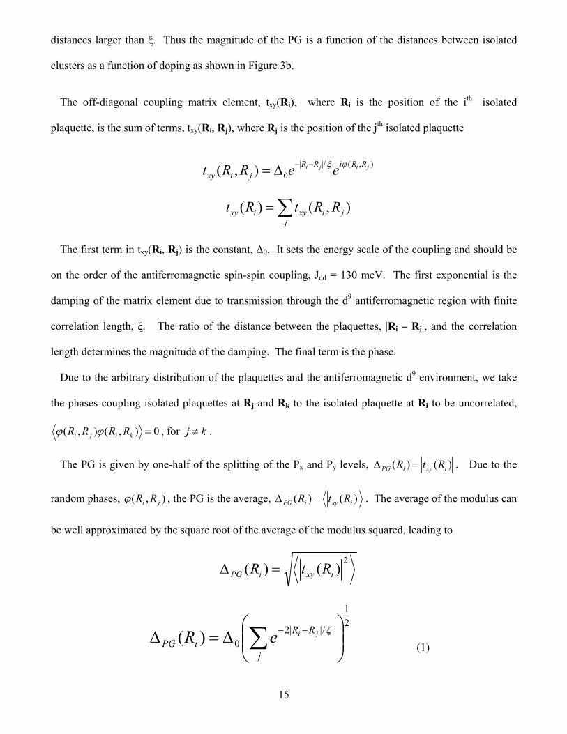
distances larger than ξ. Thus the magnitude of the PG is a function of the distances between isolated
clusters as a function of doping as shown in Figure 3b.
The off-diagonal coupling matrix element, txy(Ri), where Ri is the position of the ith isolated
plaquette, is the sum of terms, txy(Ri, Rj), where Rj is the position of the jth isolated plaquette
),(|/|0),( jiji RRiRR
jixy eeRRt
j
jixyixy RRtRt ),()(
The first term in txy(Ri, Rj) is the constant, Δ0. It sets the energy scale of the coupling and should be
on the order of the antiferromagnetic spin-spin coupling, Jdd = 130 meV. The first exponential is the
damping of the matrix element due to transmission through the d9 antiferromagnetic region with finite
correlation length, ξ. The ratio of the distance between the plaquettes, |Ri – Rj|, and the correlation
length determines the magnitude of the damping. The final term is the phase.
Due to the arbitrary distribution of the plaquettes and the antiferromagnetic d9 environment, we take
the phases coupling isolated plaquettes at Rj and Rk to the isolated plaquette at Ri to be uncorrelated,
0),(),( kiji RRRR , for kj .
The PG is given by one-half of the splitting of the Px and Py levels, )()( ixyiPG RtR . Due to the
random phases, ),( ji RR , the PG is the average, )()( ixyiPG RtR . The average of the modulus can
be well approximated by the square root of the average of the modulus squared, leading to
2)()( ixyiPG RtR
2
1
/||20)(
j
RRiPG
jieR
(1)

16
Neutron spin scattering experiments find the correlation length to be approximately equal to the mean
spacing of holes, x
a , where a is the nearest-neighbor Cu-Cu distance (a ≈ 3.8 Å) and x is the
doping.HH
27HH The above expression is used to compute the PG curve shown in the main text.
An analytic expression for the PG
An approximate analytic expression for ΔPG can be obtained from the computed number of isolated
plaquettes as a function of doping, N4. Due to the exponential decay of the matrix element with length
scale, ξ, only isolated plaquettes inside an area on the order of ~ ξ2 can contribute to the sum in Equation
1. Let a be the Cu-Cu distance in the plane and N equal the total number of Cu sites in the plane.
Then the average number of isolated plaquettes in the area A is
24
Na
NA . Substituting A = ξ2 leads to
the approximate analytic expression
Nx
N
Na
NPG
402
24
0
0 is a constant close to Δ0. Figure S3 shows the fit to the analytic expression above. The fit is
quite good, but the exact evaluation of Equation 1 leads to a better fit.
Inhomogeneous PG determination
Equation 1 leads to a different value for the PG for each isolated plaquettes. STM measurements
observed an inhomogeneous distribution of the PG with an approximately doping independent standard
deviation of ~ 10 – 20 meV. Our calculations also find an approximately constant value of ~ 15 meV.

17
Figure S3. Comparison of calculated PG curve using Equation 1 and the approximate analytic
expression, NxN
PG4
0 , where 0 82.4 meV. Here, N4 is the total number of isolated
plaquettes at doping, x. N is the total number of Cu atoms. The dotted curve is the analytic expression
and the solid black curve is calculated from Equation 1. The dashed curve is the superconducting gap,
Δ, for YBa2Cu3O7-δ where we use 2Δ/kTc = 3.5 and obtain Tc using the approximate equation,28
2
max,)16.0(6.821
xTT
c
c , where Tc,max = 93 K. The PG from the analytic expression remains
non-zero for slightly higher dopings than 0.20 and does not obtain as large of a PG for low doping as the
computed result from Equation 1. The data points in the figure are taken from Tallon et al.HH
29

18
Figure S4. The evolution of the metal sites and isolated plaquettes with doping. In (a), the number of
doped Cu sites per total Cu sites is plotted as a function of doping. Above ≈ 0.05 doping, when the
plaquettes percolate through the crystal, a metallic Cu x2y2/O pσ band is formed in the percolating
swath. The curve increases as x4 up to ≈ 0.187 because each plaquette dopes four Cu sites. Further
doping increases the doped Cu sites by x3 up to ≈ 0.226, by x2 from 0.226 – 0.271, and then by x until
0.317 when all Cu sites become doped (metallic). (b) shows the number of isolated 4-site clusters as a
function of doping. For extremely low doping, all plaquettes are isolated and the curve increases as x .

19
There is a peak at ≈ 0.058. At x ≈ 0.20, the number of isolated plaquettes becomes almost zero and the
PG vanishes.
References
(1) Newman, M. E. J.; Ziff, R. M. Fast Monte Carlo Algorithm for Site or Bond Percolation. Phys Rev E. 2001, 6401, 016706.
(2) Yu, J. J.; Freeman, A. J.; Xu, J. H. Electronically Driven Instabilities and Superconductivity in the Layered La2-XBaxCuO4 Perovskites. Phys Rev Lett. 1987, 58, 1035-1037.
(3) Mattheiss, L. F. Electronic Band Properties and Superconductivity in La2-YXyCuO4. Phys Rev Lett. 1987, 58, 1028-1030.
(4) Pickett, W. E. Electronic-Structure of the High-Temperature Oxide Superconductors. Rev Mod Phys. 1989, 61, 433-512.
(5) Perry, J. K.; Tahir-Kheli, J.; Goddard, W. A. (unpublished). 2001. (6) Perdew, J. P.; Levy, M. Physical Content of the Exact Kohn-Sham Orbital Energies - Band-Gaps
and Derivative Discontinuities. Phys Rev Lett. 1983, 51, 1884-1887. (7) Sham, L. J.; Schluter, M. Density-Functional Theory of the Energy-Gap. Phys Rev Lett. 1983,
51, 1888-1891. (8) Perdew, J. P.; Zunger, A. Self-Interaction Correction to Density-Functional Approximations for
Many-Electron Systems. Phys Rev B. 1981, 23, 5048-5079. (9) Svane, A. Electronic-Structure of La2CuO4 in the Self-Interaction-Corrected Density Functional
Formalism. Phys Rev Lett. 1992, 68, 1900-1903. (10) Temmerman, W. M.; Szotek, Z.; Winter, H. Self-Interaction-Corrected Electronic-Structure of
La2CuO4. Phys Rev B. 1993, 47, 11533-11536. (11) Czyzyk, M. T.; Sawatzky, G. A. Local-Density Functional and on-Site Correlations - the
Electronic-Structure of La2CuO4 and LaCuO3. Phys Rev B. 1994, 49, 14211-14228. (12) Perry, J. K.; Tahir-Kheli, J.; Goddard, W. A. Antiferromagnetic Band Structure of La2CuO4:
Becke-3-Lee-Yang-Parr Calculations. Phys Rev B. 2001, 63, 144510. (13) Perry, J. K.; Tahir-Kheli, J.; Goddard, W. A. Ab Initio Evidence for the Formation of Impurity
d3z2-r2 Holes in Doped La2-xSrxCuO4. Phys Rev B. 2002, 65, 144501. (14) Xu, X.; Goddard, W. A. The X3LYP Extended Density Functional for Accurate Descriptions of
Nonbond Interactions, Spin States, and Thermochemical Properties. P Natl Acad Sci USA. 2004, 101, 2673-2677.
(15) Bryantsev, V. S.; Diallo, M. S.; van Duin, A. C. T.; Goddard, W. A. Evaluation of B3LYP, X3LYP, and M06-Class Density Functionals for Predicting the Binding Energies of Neutral, Protonated, and Deprotonated Water Clusters. J Chem Theory Comput. 2009, 5, 1016-1026.
(16) Curtiss, L. A.; Raghavachari, K.; Trucks, G. W.; Pople, J. A. Gaussian-2 Theory for Molecular-Energies of 1st-Row and 2nd-Row Compounds. J Chem Phys. 1991, 94, 7221-7230.
(17) Curtiss, L. A.; Raghavachari, K.; Redfern, P. C.; Pople, J. A. Assessment of Gaussian-2 and Density Functional Theories for the Computation of Enthalpies of Formation. J Chem Phys. 1997, 106, 1063-1079.
(18) Matsuda, Y.; Tahir-Kheli, J.; Goddard, W. A. Definitive Band Gaps for Single-Wall Carbon Nanotubes. J Phys Chem Lett. 2010, 1, 2946-2950.
(19) Xiao, H.; Tahir-Kheli, J.; Goddard, W. A. Accurate Band Gaps for Semiconductors from Density Functional Theory. J Phys Chem Lett. 2011, 2, 212-217.
(20) Mori-Sanchez, P.; Cohen, A. J.; Yang, W. T. Localization and Delocalization Errors in Density Functional Theory and Implications for Band-Gap Prediction. Phys Rev Lett. 2008, 100, 146401.

20
(21) Haskel, D.; Stern, E. A.; Hinks, D. G.; Mitchell, A. W.; Jorgensen, J. D. Altered Sr Environment in La2-xSrxCuO4. Phys Rev B. 1997, 56, R521-R524.
(22) Tahir-Kheli, J.; Goddard, W. A. Chiral Plaquette Polaron Theory of Cuprate Superconductivity. Phys Rev B. 2007, 76, 014514.
(23) Tahir-Kheli, J.; Goddard, W. A. The Chiral Plaquette Polaron Paradigm (CPPP) for High Temperature Cuprate Superconductors. Chem Phys Lett. 2009, 472, 153-165.
(24) Tahir-Kheli, J.; Goddard, W. A. Universal Properties of Cuprate Superconductors: Tc Phase Diagram, Room-Temperature Thermopower, Neutron Spin Resonance, and STM Incommensurability Explained in Terms of Chiral Plaquette Pairing. J Phys Chem Lett. 2010, 1, 1290-1295.
(25) Hashimoto, M.; He, R. H.; Tanaka, K.; Testaud, J. P.; Meevasana, W.; Moore, R. G.; Lu, D. H.; Yao, H.; Yoshida, Y.; Eisaki, H. et al. Particle-Hole Symmetry Breaking in the Pseudogap State of Bi2201. Nat Phys. 2010, 6, 414-418.
(26) He, R. H.; Hashimoto, M.; Karapetyan, H.; Koralek, J. D.; Hinton, J. P.; Testaud, J. P.; Nathan, V.; Yoshida, Y.; Yao, H.; Tanaka, K. et al. From a Single-Band Metal to a High-Temperature Superconductor via Two Thermal Phase Transitions. Science. 2011, 331, 1579-1583.
(27) Kastner, M. A.; Birgeneau, R. J.; Shirane, G.; Endoh, Y. Magnetic, Transport, and Optical Properties of Monolayer Copper Oxides. Rev Mod Phys. 1998, 70, 897-928.
(28) Presland, M. R.; Tallon, J. L.; Buckley, R. G.; Liu, R. S.; Flower, N. E. General Trends in Oxygen Stoichiometry Effects on Tc in Bi and Tl Superconductors. Physica C. 1991, 176, 95-105.
(29) Tallon, J. L.; Loram, J. W. The Doping Dependence of T* - What is the Real high-Tc Phase Diagram? Physica C. 2001, 349, 53-68.