organisation chart of electrical …...kptcl/bescom at 66 kv in double circuit tapping from 66 kv...
TRANSCRIPT

CEE CME
CWE / W
SEE / HQ
CWE / A
DY.CME / ASMDY.CME / WSM
SEE / W SEE / A
AEE / P-I
SSE / WSP SSE / ASP
AEE / W - I AEE / W - II
SSE / WSCSSE / Col.SSE / Admn.
AEE / P-II
SSE / MRSSSE / DG. SSE / ASC
AEE / A
ORGANISATION CHART OF ELECTRICAL DEPARTMENT
TECHNICAL CONTROL OF CONTROL GROUP UNDER CEE
ADMINISTRATIVE CONTROL OF CONTROL GROUP UNDER CME
SSE / TECHSSE / EDO SSE / WSC
SEE / MRS
1

BRIEF ABOUT FACTORY
Till early 1980s Indian Railways was importing about 55% of requirement of wheels and axles. Indigenous capacity was available only at Tata Iron & Steel Company [TISCO] and Durgapur Steel Plant [DSP]. The TISCO plant was technically not capable of meeting the changing requirement of wheels and axles for the new designs of rolling stock and production was discontinued. DSP was only able to partially meet Indian Railways’ needs. The cost of imports was high with prices rising in the world market. Financing of imports, delays in supplies and limited availability of foreign exchange adversely affected wagon production and rolling stock maintenance. It was in this context that in the early 1970s the Railway Ministry felt the necessity for setting up a new specialized Production Unit for manufacture of rolling stock wheels and axles as import substitute. The ultimate objective was that DSP and the Rail Wheel Factory [RWF, formerly Wheel & Axle Plant] should be able to totally meet Indian Railways requirement for standard wheels and axles so that their import could be stopped.
The Planning Commission sanctioned the Rail Wheel Factory Plant project in 1978 at a cost of Rs.146 Crores. Trial production commenced during 1983, manufacturing 70000 Wheels and 20000 Axles per annum. Late Smt. Indira Gandhi, the then Prime Minister of India formally commissioned the plant on 15 September 1984.
Rail Wheel Factory spreaded over in 250 acres area is situated in Yelahanka Bangalore (India). It is a state-of-the-art plant, meeting bulk of the requirement of wheels, axles and wheel sets for the Indian Railways. The spare capacity available is profitably utilized to meet the domestic demands for non-railway customers and exports.
The plant is certified for ISO-9001: 2008 and ISO-14001: 1994 standards by M/s. BVQI. It is also certified to confirm to the Quality Assurance Program of Association of American Railroads (AAR) in respect of manufacture of new wheels and axles.
All products are subjected to stage and final inspection, starting from the chemical composition of the molten metal till the final inspection. This includes micro/macro properties of the material, Magnetic Particle Testing, Ultrasonic Testing, Hardness, warpage, dimensional parameters, surface finish etc.
2

RWF consists of broadly 3 Units (One Unit for the manufacture of Wheels by a specialized casting technology using high capacity electric arc melting furnaces; one Unit for the manufacture of Axles by forging of billets received from DSP, and one Unit for the assembly of wheel sets). The factory has got 4 main shops, viz, Wheel shop, Axle Shop, Assembly and Finishing Shops and Millwright Shop. The factory complex also includes Administrative Offices, Staff Quarters and other ancillary facilities. Manufacturing of Wheel & Axle in RWF is fully automatic. Earlier processing was PLC based control system, and now changed to CNC based control system. All machines in factory are imported and having sophisticated control system and software. For maintenance and repair of equipments, control system, software the need of Electronic Lab was felt necessary and have set up the same in 1984. The technology adopted in Rail wheel Factory is the most sophisticated incorporating particularly the latest developments in Electrical and Electronic Engineering. The Plant can boast of “Ultra High Power” Arc Furnace installation (U.H.P) with vacuum breakers, which is the “First” in the country. The Plant can also boast of many “Firsts” in certain areas of process controls by Microprocessor based Programmable Logic Controllers (PLCs) Computerized Numerical Controlled machines and large scale adoption of Electronic Control and Instrumentation. IN Rail Wheel Factory, Chief Electrical Engineer heads the Electrical Department and assisted by four senior scale officers and Six Junior Scale officers. The main function of the Department is divided into two categories namely Power group and Control group. The power group looks after the activities of receiving incoming power from KPTCL/BESCOM at 66 KV in double circuit tapping from 66 KV inter connected bus of Peenya and Hoskote grids to provide uninterrupted power supply, and after stepping down to 11 KV , taken to 14 Nos 11 KV/ 440 V HT sub-stations located in respective area inside factory for feeding power supply to various machineries, pump houses, compressor rooms, wheel shop, axle shop and for Illumination of entire factory and colony, Administrative office, etc. The control group looks after the maintenance of various control equipments & up keeping of their functions.
3

ELECTRICAL STATISTICS
Connected Load --- 85 MVA Maximum Demand --- 28MVA Contract Demand --- 28 MVA Electricity Supply Voltage --- 66 kV 15 MVA Power Transformers --- 5 Nos. 10 MVA Power Transformers --- 1 Nos (which is under up gradation to 15 KVA ) 66 kV SF6 Circuit Breakers ---- 6 Sets 66 kV Control Panel ---- 6 Sets. 11 kV/440 V Distribution Transformers --- 57 Nos. of various capacities. Low Tension& HT VCB/ACBs --- 100 Nos. 13.5 MVA Furnace Trnsf. --- 3 Nos. Electrical Energy Consumption : Approx. 15 Million units per month
Avg. Energy Bill paid to KPTCL : Approx. Rs. 8 crore / month KPTCL TARIFF CHARGES:- Maximum Demand Charges at Rs.180/- per KVA
1st 1,00,000 units Rs.4.60 per unit Plant
Balance units Rs.5.00 per unit
Colony Total No. of Units Rs.5.00 per unit
Plus 5% Tax
• Energy consumed for the year 2010–11 for plant 145681370 units and
payment made Rs.7,40,80,508/-. • Energy consumed for the year 2010 – 11 for colony & service Building is
1736470 units and payment made Rs.74,15,432/-
POWER SUPPLY ARRANGEMENTS
a) Source of Power Supply: RWF is characteristically an Energy intensive plant with connected load of 85 MVA and Contract Demand of 28 MVA, which is controlled through MD controllers. When all the 3 furnaces was simultaneously Maximum Demand fluctuates to 32 MVA, for melting the raw material (scrap) for manufacturing
4

wheel. Each EAF is rated at 13.5 MVA. The load of only furnaces comes around 63% of the total energy consumption.
RAIL WHEEL FACTORY
FEDERAL MOGHUL
KHB YNK2 X 20 MVA
YNK DG PLANT
ATTUR / YNK
VIDYANAGAR2 X 20 MVA
GRINDWELL NORTON
MANYATHA2 X 20 MVA
SAHAKARNAGAR 2 X 20 MVA220 KV
8 POLE STRUCTURECB HALLI
SOLADEVANAHALLI2 X 20 MVA
PLATINUM CITY2 X 31.5 MVAWELL CAST
2 X 20 MVA
SRS PEENYA
GOKULA2 X 20 MVA
MATHIKERE2 X 20 MVA
HEBBAL
CPRI
DRAKE
2 X 67.5 + 2 X 150 MVA3 X 20 + 1 x 31.5 MVA
The power supply is availed from M/S. Bangalore Electricity Supply Company Ltd., (BESCOM) through double circuit 66 KV Transmission line (Approx. 2.5 Km), drawn from Diesel Generating Plant of KPCL in Yelahanka through common connected feeder from SRS Peenya & Hoskote grids. Since RWF being is a continuous and automatic processed Plant. In case of failure of power supply the item under manufacturing process stopped in then and their position which becomes cold if interruption of power supply 10 to 15 Mnts and has to be lifted as scrapped. Besides this the on going process is to be taken back and then normalized by running a complete dummy process then only further manufacturing can be started. Hence, it needs the an uninterrupted power supply. Out of total Connected Load of 85 MVA, about 4 to 5 MVA is Essential Load which requires to be fed continuously regardless of the Power Supply availability. Hence for operation of essential load in case of failure of normal power supply, the 2 Nos. Diesel Generating sets (11 KV DG Sets each 1750 KW (2190KVA capacity). have been provided having some special features not so far incorporated in diesel generator sets normally used in Open Line Railways and Production Units. Such as i) 11 kV High Tension generation. ii) Two sets to be synchronized and operated in parallel iii) Automatic cut-in facility for essential loads. (presently not used)
COYOTE
COYOTE
COYOTE
COYOTE
COYOTE
COYOTE
COYOTE
COYOTE
DRAKE
DRAKE
TO HOODY
TO HOSKOTE
12 POLESTRUCTURE
COYOTE
COYOTE
DRAKEDG-1DG-2
NELAMANGALA
TO DB PURA
COPPER + COYOTE
COYOTE
New YNKPROPOSED 220 KV TO RWF
CB ERECTED PRESENTLY
5

b) Power Supply Arrangements to factory: As brought out above, the power supply for RWF is received at 66KV and further stepped down to 11kV in the Main Receiving Station being set up by the Railways within the factory complex. Adequate installed transformer capacity has been planned in such a way every where so as to cater for standby arrangements.
MRS
AF-1 AF-2 AF-3
200
X 3
200
X 3
280
X 3
275
X 3
405
X 3
405
X 3
246
X 1
240
X 1
245
X 1
223
X 1
( Spa
re )
290 X 2
290 X 2
FUME
COOLING TOWERNON ESS. ESS.
WHEEL SHOP
COMP. TUBE
GFM S/SAXLE S/SNON ESS.ESS.EMMS
SS/3 TYPE-3
E.COL , SS-5 HOSP. SS-2 SS/6STADIUM
SS/4 TYPE-2
DG-1 DG-2 DG-3
MOULD 1 MOULD 2
ASSLY.
ADMN.CANTEEN
645
X 2
; 667
/524
X 1
/Run
( 4-
Tota
l )
290/492 X 1/Run
(713 / 669) X 1/Run
570/480 X 1/Run
368/342 X 1/Run
500 X
1
400 X
1
320 X 2
625 X
2
500/502 X 1/Run
642 X 2
280 X 2
252 X 1
430 X 2 165 X 1
510 X 4
585 / 806 X 1/Run
246
X 1
107 X 2
290 X 2253 X 2
300 X 2
175 X 3
185 X 3
257 X 1
413 X 1
1401 X
1
916 /
900 /
1015
X 1/Run
277 X 1 15X 1
95 sq.mm185 sq.mm400 sq.mm
66/11kv Ring Main System of RWF 5 Nos. 15MVA, & 1 No. 10 MVA ( Under up-gradation to 15 MVA ) 66/11kV Power Transformers have been located in the out-door switch yard. The 11kV Switchgear panels and associated equipments such as 66kV Relay Control Panels, Battery and Battery Charging and L.T panels have been located in the in-door control room. Three Arc Furnaces are being fed on 11kV from four 15MVA Transformers (T1, T2, T3 & T4) and the remaining two Transformers (T5, T6) feed to the General loads including the colony etc.
6

FRO
GOSGOS
WAP-1
WAP-2 LINE-4
LINE-3M DG HOUSE YNK FROM SRS PEENYA
66 KV BUS 66 KV BUS
15 MVA66/11 KV
10 MVA66/11 KV
15 MVA66/11 KV
15 MVA66/11 KV
15 MVA66/11 KV
VCB 1250A(32)
(36)VCB 1250A
proposed DG-3
PROPOSEDSF-6 CB 1600A 72.5 KV
BY-PASSGOS
DG HOUSE OF RWFCOMISIONED on: 06.04.1985
RWF MRS YARD
VCB1250A
VCB1250A
VCB1250A
VCB1250A
VCB1250A
B/CEXISTING.SF-6 CB 1600A 72.5 KV
ALL INCOMER & B/C VCBs EXCEPT B/C-5 ARE 1250AALL O/G VCBs & B/C-5 ARE 800A
MRS COMISIONED ON 28.11.1982
SF-6 CB 1600A 72.5 KV
SF-6 CB 1600A 72.5 KV
SF-6 CB 1600A 72.5 KV
SF-6 CB 1600A 72.5 KV
OH LINE 66 KV DOUBLE INCOMER
GOS
GOS
SF-6 CB 1600A 72.5 KV
TR-5
GOS
TR-1
VCB 1250AABB(2)
VCB 1250AABB(6)
TR-2 TR-3
VCB 1250AABB(11)
VCB 1250AABB(15)
TR-4TR-6
MOCB
VCB1250AABB(28)
DG-2DG-1
VCB 1250AABB(21)
MAIN RECIEVING STATION , 66 / 11KV
NOTE:11KV BREAKERSFROM 1 TO 31 & 39 - ABB (VCB's)FROM 32 TO 38 EASUN (VCB's)
LINE-3LINE-4
CT (RWF)
1750 KW x 2Nos.
2400 KW x 1No.LA LA
LA LA LALA
LALA
BESCOM PT
BESCOM METERING
BESCOM CT
GOS GOS GOS GOS GOS GOS
15 MVA66/11 KV
PT (RWF)
A A A A A
A
66 KV BUS
B/C
11 KV BUS11 KV BUS11 KV BUS 11 KV BUS 11 KV BUS11 KV BUS
ADOPTER BOX
B/C-6 VCB(35)1250A
ADOPTER BOX
TR-5 INCOMER
TR-1 INCOMER TR-2 INCOMER
TR-6 INCOMER
TR-4 INCOMER
DG-1 INCOMER
DG-2 INCOMER
TR-3 INCOMER
B/C-5 VCB(23)800A
B/C-4 VCB(19)1250A
B/C-3 VCB(12)1250A
B/C-2 VCB(8)1250A
B/C-1 VCB(4)1250A
B/C-7 VCB(30) 1250A
DG-3 INCOMER
VCB1250A
VCB1250A
VCB 1250AABB(15)
GOSGOS
Schematic Diagram of MRS / RWF 11kV Bus has been sectionalized to segregate the furnace loads and the general shop loads so that the voltage fluctuations due to operation of Electric Arc Furnaces do no affect the working of other Electrical machinery comprising the general shop loads.
7
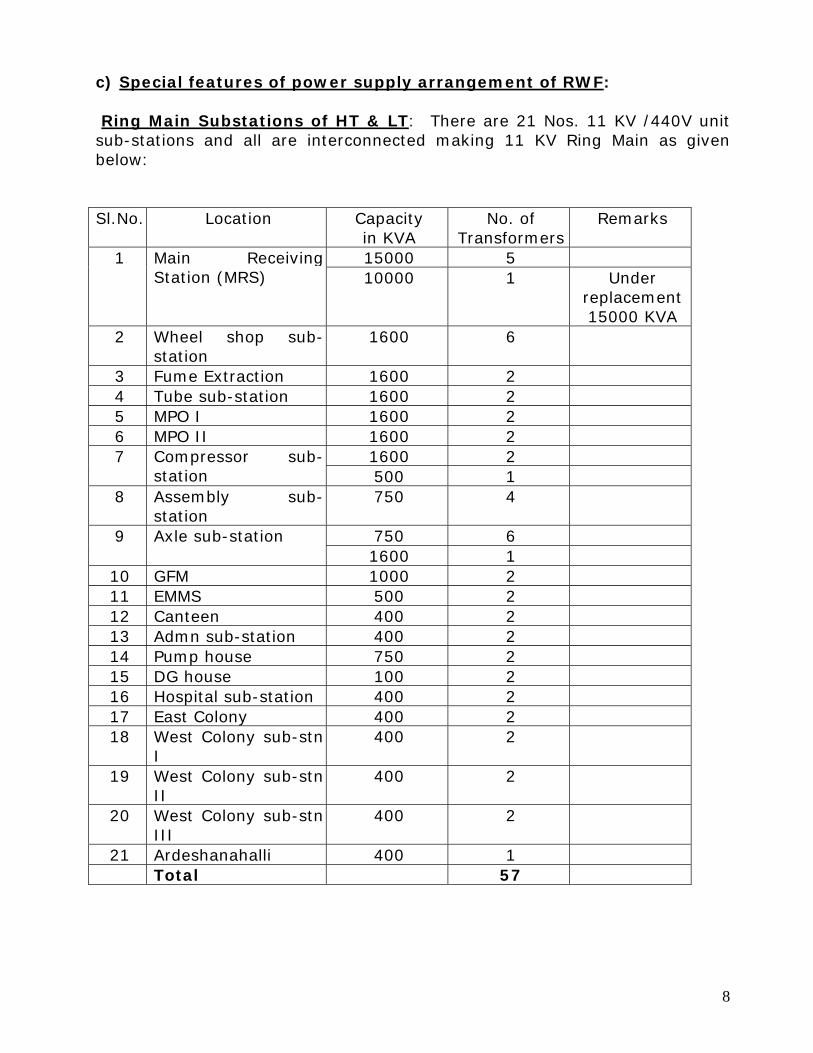
c) Special features of power supply arrangement of RWF: Ring Main Substations of HT & LT: There are 21 Nos. 11 KV /440V unit sub-stations and all are interconnected making 11 KV Ring Main as given below: Sl.No. Location Capacity
in KVA No. of
Transformers Remarks
15000 5 1 Main ReceivingStation (MRS) 10000 1 Under
replacement 15000 KVA
2 Wheel shop sub-station
1600 6
3 Fume Extraction 1600 2 4 Tube sub-station 1600 2 5 MPO I 1600 2 6 MPO II 1600 2
1600 2 7 Compressor sub-station 500 1
8 Assembly sub-station
750 4
750 6 9 Axle sub-station 1600 1
10 GFM 1000 2 11 EMMS 500 2 12 Canteen 400 2 13 Admn sub-station 400 2 14 Pump house 750 2 15 DG house 100 2 16 Hospital sub-station 400 2 17 East Colony 400 2 18 West Colony sub-stn
I 400 2
19 West Colony sub-stnII
400 2
20 West Colony sub-stnIII
400 2
21 Ardeshanahalli 400 1 Total 57
8

Power Cabling: About 25 KM of 11kV XLPE cables have been used for the Ring Main System, and radial feeders to arc furnaces and unit substation. The concept of cable tunnels has been adopted to lay a large number of cables through difficult routings for both Wheel and Axle shops in selected areas. Ventilation arrangements have also been installed in the cable tunnels so as to ensure that the cables are operated within the permissible temperature limits. WHEEL UNIT Arc Furnace: The Arc Furnace installation falling under “Ultra High Power” category which is the most sophisticated and ‘First’ of its kind to be set up in the country. The Three Arc Furnaces of 23 Ton Capacity are fed each by 12.1 / 13.55 MVA power supply. The transformer rating of more than 0.5 MVA per ton of charge is termed as “Ultra High Power” (U.H.P) furnace in modern classification. The concept of UHP has been adopted as this permits 20 to 30% more power being punched into the charge on the top tap at each time of melting so as to reduce the “Melt Down Time” by as much as 10 minutes and thereby increasing the productivity of the system. The impact of this saving in melting time is of tremendous importance in a “Single Slag” practice using selected scrap. H.T Power Supply: The three Arc Furnaces constitute the heart of the wheel production and these three furnaces have to be worked continuously in 3 shifts round the clock. Accordingly, duplicate/triplicate 11 kV feeders have been laid from the Main Receiving Station for all the three arc furnaces as well as critical machineries so as to ensure uninterrupted power supply to them. Although normally the arc furnaces F1, F2 and F3 in Wheel Unit are fed form 15 MVA 66/11 kV power transformers T1, T2 and T3 in Main Receiving Station respectively even then the flexibility in power supply arrangement has been
9
built in such that all the three furnaces can be feed from independent transformers also in addition paralleling of the transformers. Vacuum Switchgear: The duty cycle for a furnace circuit breaker is usually very arduous. A furnace circuit breaker usually operates about 140-180 times in a day of 3 shifts: twenty to twenty five of these operations can be “On Load” or under “Short Circuit” conditions. A standard oil circuit breaker working under such operating conditions would require almost daily maintenance and weekly once or twice oil change to be able to be able to cope up with this nature of duties. Some times Air blast circuit breakers are advantageously employed under such conditions, but require additional compressed air equipment. The RWF furnaces are being provided with vacuum circuit breakers. The main advantage here is that since the current is interrupted under near vacuum condition, there are practically no arcing, reducing contact damages due to pitting which is predominant in the case of oil or air circuit breakers. In some installations vacuum switches have also been used (specially in U.S.) for this application. But these vacuum switches still require a back up breaker to cater for “ short circuit and fault condition” tripping. In the case of the scheme for control in RWF furnaces the function of both the vacuum switch as well as the back up circuit breaker is handled by the vacuum circuit breaker. The Furnace Transformers are protected with Two-stage Protection Scheme. which facilitates the discrimination of L.T. Fault from L.T Over-current fault which normally associated with Arc Furnace operation. With this protection, the number of unnecessary Circuit Breaker Trippings are reduced to a minimum, thereby increasing the circuit breaker’s operational life. Features of Furnace Transformers: The Arc Furnace transformers have been specially designed to give a continuous rating of 12100 KVA and an average load of 12% to 13500 KVA for 2 hours during melt down conditions in a duty cycle of 3.5 hours. Impulse level of HT winding has been designed to 110 KV. The transformer is of oil forced water cooled (OFWC) . To vary the secondary voltage an off load 9 position tap changer is provided. The transformer is having 4 constant voltage taps to cater for varying melting conditions. The transformer is Delta/Delta connected with secondary open Delta to provide interleaved secondary bus bar carrying nearly 30000 Amps. The Secondary Delta is connected through a bus which further connected to electrode arms and after that making a Delta to provide compensated reactance system. In addition to standard accessories the transformer is fitted
10

with Qualitrol pressure device to sense and relieve instantaneously any pressure build up in the transformer. The winding temperature indication is fitted with repeater dials for remote indication. The secondary current for the furnace transformer is of the order of 30KA, such high current naturally gives rise to high (I2t) heating losses in the secondary circuit. Therefore the flexible cables from the transformer Bus bars to the bus tubes on the furnace have been planned with water cooled cables. These cables are of large geometric mean dia +water cooled cables of size 4000 MCM. The large dia cables are structurally more stable and resist the electrical/mechanical push pull force due to strong magnetic forces between the adjacent phases. These cables are fitted with chafing bumpers to prevent rubbing of outer sheaths of the cables. Butterfly arrangement of Bus Tube: Design and layout of Arc Furnace secondary systems are very important to ensure maximum phase balance (to eliminate wild phasing effect) with minimum reactance. Where as in the lower capacity furnaces it is usually standard to introduce extra reactance in the circuit to obtain a stable Arc. In furnaces of higher capacity the inherent series reactance is already very high and methods have to be devised to see that the high reactance of the circuit does not result in very low power factor. Low power factor could not only cause higher energy charges but would also reduce the power available to the arc and thus waste the higher capacity available in the transformer. A number of methods have been devised to reduce the reactance of the secondary circuit. The RWF furnaces have been planned with single butterfly system of busbar having the following advantages: Low system reactance, Better reactance balance in dynamic conditions, More Arc power at the same voltage when compared to other systems, Low refractory wear due to shorter Arcs. Power Factor Capacitor: To improve the furnace power factor, three banks of 3600 KVAR of 11 KV HT capacitors for each furnace with manual switching arrangements have been located at Main Receiving Station. In addition to the capacitor, surge and harmonic suppression reactor of suitable rating have also been incorporated. To provide quick discharge, RVT has been fitted which will also provide protection against unbalancing due to unit failure. The control system employed for the electrode movement is of thyristor controlled DC motor in addition counter weight balancing is also provided for optimum response of the electrode. Micro processesor based molten metal
11

temperature indicator has been provided for measuring the molten metal temperature. In addition to the indicator, disposable dip type thermocouple and an annunciation panel complete with signal lights and an audible alarm have been provided for taking the correct molten metal temperature measurement in each furnace. To analyze the composition of elements during a melt on line computer based spectrometer & hydrogen determinator are provided .
Fume Extraction, Ventilation & Roof Extraction systems:
To maintain a pollution free environment in melting area complete fume extraction and big exhaust fans have been provided on the roof. The fumes are extracted from the furnace indirectly through creation of long draft and then through the ducts then to baffle chambers to arrest spark carry over particles from the furnaces, the fumes are then passed through the bag filters and finally discharged to the atmosphere through a common stack. In addition to fume extraction systems, special ventilation system has also been provided for the Operator’s comfort in the melting area and to maintain a dust free atmosphere inside the control rooms. Moulding Room Conveyor system
The Moulding room Conveyor system which handles moulds (cope and drags) and Hot wheels are controlled Programmable logic control panels. These conveyors have been interfaced with various equipments to perform operations lke (a) cope and drag cleaning, (b) cope drag spray, (c) riser and dome core bakers, (d) riser and dome knockout, (e) stamping, etc. In addition to these panels, the individual interfaced equipments are being controlled by their respective control panels, which are also working on the Programmable logic principle. Sophisticated conveyor system in the moulding room with interfaced equipments works on Programmable logic control panels. Such as contactors, relays, timers, limit switches, etc. totaling about 2000. This conveyor control equipment alone is equivalent 40 AC Electric Locomotives.
12

Special Features of Control and Electronic Engineering in Wheel Unit
Wheel Unit can also boast of “First” in certain areas of Control and Electronic Engineering. The Plant can also boast of lot of sophistication with modern approach while maintaining a fairly good blend of traditional approach to problems encountered in a process industry. A few “Firsts” among Railway Establishments are (1) Thyristor Controlled EOT Cranes, (2) Thyristor controlled electrical furnaces using PID Controllers, (3) Adoption of Microprocessor based Programmable Logic Controllers for conveyor controls involving counting, memory, memory shift and routing requirements, (4) Detection of objects in furnace using LASER beam. Thyristor Controlled EOT Cranes: To meet the process requirements in Melting Shop ladle containing the hot metel weighing about 35 tonnes has to be carefully lowered in to the pressure pouring pit. As the clearances between the ladle and the pit is of the order of only one or two inches, it is necessary to have a precise load control which is independent of the crane operator’s skill for the 3 Nos. 35 Tonne Class-IV duty hot metal cranes.
Speed Control: For purposes of speed control of slip ring induction motor, various techniques like rotor resistance control, Stator voltage and Stator frequency control are employed. While conventional method of speed control by varying the rotor resistance is retained on most of the Cranes, Speed Control on Hot Metal Cranes (3 Nos.), Axle Forge Cranes (2 Nos.) and mill providing cranes (2 Nos.), which require precise control, is done using thyristor controls for varying the stator voltage. Principle of operation is briefly explained below: Essentially the arrangement is a double feed back system, viz., (a) Speed feed back and (b) Current feed back. Reference signal generates a reference voltage for the control by adding or subtracting certain resistances in the circuit depending upon the position of master controller. This reference signal is compared with a feed back signal, which is derived from the output of a tacho generator (which is proportional to the actual speed). The error signal generated is then amplified and used as reference signal for the current loop. Current feed back sensed by C.Ts. and rectified by the associated bridge is compared with the reference signal. The output of this loop is fed to pulsing circuit which controls the firing of Thyristor. The technique of phase angle shift firing is employed in the system. Current feed back circuit could be tuned to restrict the maximum current flow in the motor as a percentage of full load current.
13

As a direct consequence, adoption of thyristors, results in the following advantages:
(i) Load independent speed control. (ii) Reduction of rotor resistance grids resulting in reduced power
loss. (iii) As a consequence of (ii) above, reduced number of rotor
contractors (one instead of 4 normally used) and hence reduced maintenance.
(iv) Totally interchangeable control circuit boards (PCB) between cranes.
In addition to the above, the system has special provisions like:
(i) Toruqe failure protection for tripping the mechanical brake when motor torque is absent or incorrect.
(ii) Brakes coming ‘ON’ at near zero speed resulting in increased brake liner life.
(B) Lifting Magnets and Battery Back up: The hot metal cranes for the Wheel shop and the Mill Providing Cranes in Axle shop as also cranes in the Scrap Pre-conditioning Shop have been provided with magnets to handle steel required as raw material for the Arc Furnaces and forge. In the case of the magnets provided for the hot metal cranes in Wheel shop, the magnets are specially designed for working in hot environment. This was found essential because when charging into the Arc Furnace directly, which is some times necessary, magnet has to encounter and handle comparatively very hot temperatures. These magnets are also water and weather proof, as a protection against moisture, which can be encountered by the magnets in the difficult working conditions. These magnets are with H. Class insulation. When working with magnets, sudden power failure can be very hazardous in as much as materials being handled may be released involuntarily and in an uncontrolled manner causing mishaps or accidents. To overcome this basic difficulty, the cranes have been provided with a capability of 10 minutes working in case of power failure. The circuit is so designed that the battery is normally floating and immediately on failure of the A.C. power, the battery comes into operation thereby ensuring continuity of D.C. power supply to the magnets. An audiovisual alarm is simultaneously energized to give the Driver an indication of power failure, so that he can take immediate corrective action.
14

Furnace Temperature Control
There are two distinct types of furnaces –viz., (a) Oil fired and (b) Electrically heated, and in the latter group again two more divisions exist-one requiring fine control (e.g., Tube Furnaces) and the other coarse control (e.g., Mould Furnaces). However, the control is done in all the above cases by Electronic Proportional, integral plus derivative controllers (PID). The function of integral control is to reduce steady state errors while derivative control takes care of transient errors. The operation is best explained by a simple block diagram:
Ref. A
Controller & system
A temperature reference is generated within the controller itself by adjusting the dial of the controller or a pointer as the case may be, to the required value. Resistance of a potentiometer in the Controller is varied. The reference signal may be a constant signal (like for normalizing furnace, etc.) or a variable signal (like in tube pre-heat furnace). In case of a variable reference signal, the temperature reference is generated by cam followers, which can be cut in any fashion desired, to get a reference which is proportional to time. The actual system, temperature is sensed by appropriate types of thermocouples. The output of the thermocouple is a voltage signal. The two voltages (Ref. & feed back) are compared in a bridge circuit to generate error signal. As the thermocouple outputs are very small (usually in the mv range) the error signal is also small and as such requires amplification for driving final control elements. The control elements can be a motor, or step switch (Mould Furnace) or a thyristor device (Tube Furnace). The control elements are driven in the proper direction (increase / decrease), depending upon the sign of the error signal. Depending upon the operational requirements, position proportional and time proportional models of Controllers have been selected. The principle of pressure control is similar except that a pressure – volt / current transducer has to be used in place of thermocouples along with a controller to match.
15

Programmable Logic Controllers (PLC) For the Wheel Final Processing Shop (WFPS) conveyor system of Wheel shop, where routing and memory shifting is involved, we have gone in for Programmable Logic Controllers, which is a Micro-processor based unit, instead of conventional method using Reed Relays. The entire area is divided into four zones, each controlled by a PLC which has capability to accept 512 Input / Output Combinations. Basic system consists of a central processing unit (CPU), Input / Output (I/O) device, memory unit and power supply unit. The memory unit has a maximum capacity of 8K-16 bit words in steps of 2K. Some of the advantages resulting from the uses of PLCs are:
(i) Facility to modify the functional requirements by simply altering the programme without changing input / output structure.
(ii) Elimination of panel wiring which can be complicated and cumbersome.
(iii) Simulation of systems without affecting the final outputs. (iv) Fault diagnostic facility using PC based software. (v) Facility to edit internal logic (Programmed) without any difficulty
which would require very long shut downs with relay logic systems. (vi) Reduced maintenance and improved reliability due to elimination of
electromagnetic relays and Contactors. Electronic Weighing Scale to weight setup load in furnace To know the weight of the scrap loaded in the furnace an electronic crane HOOK weighing system is provided on the 35 /10 Tonne crane hook one in Main hoist hook ( 50T capacity ) and the other on the auxiliary hoist hook ( 10T capacity) . The equipment works on load cells with strain gauge transducer, which works on the principle of variation in resistance when it is stressed or strained as the case may be. This variation is balanced in a wheatstone bridge which derives power from a stabilized D.C. source. The error voltage (which is proportional to the load ) is further amplified before they are finally displayed after A/D conversion. The system has facility for attaching a printer at a later date, if desired. Cutting of Hole in Wheel for Axle (Hub Cutters)
The Hub Cutting operation in wheel is done after Sprue Wash with care specially in respect of cutting speeds in order to ensure reasonably good cut. This operation is being done using Oxy Acetylene torch for both radial and circular motions driven by two independent DC shunt motors, the speed of which is controlled using Thyristors. Principally the scheme involves applying
16
constant DC voltage to the field of the shunt motors and a variable ripple DC voltage to the armature using phase angle controlled thyristors. As the speed of the shunt motor varies with the variation in the load, the regulation can be done by comparing the actual drive speed with the desired speed. The desired speed is pre set by a potentiometer while the feed back signal represents actual drive speed. The error derived from these two signals is amplified which in turn controls firing angle of the thyristor and thus the average voltage supplied to the DC Motor. In order to work the unit safely a “current limit circuit” having no effect on the drive operation. With the current reaching the pre set limit, the output of the current limit over rides error current and cause the power amplifier output to remain at a safe level. This action protects the motor and power amplifier from overload damage. The unit is available with minimum speed and maximum speed adjustments oh the printed board itself whereas the speed control between the minimum and the maximum set speeds is available to the Hub Cutting Station Operator. Also Hub cutters with CNC / PLC based control system is available in RWF for the same process. Flaw Detection (Magnaglo and Ultrasonic)
Detection of flaws in a cast wheel is a very important operation in the set up. Two stage, viz., (i) Magnaglo for surface cracks and (ii) Ultrasonic election for internal flaws are employed. These operations are interfaced with the corresponding conveyor sections. While Magnaglo is a manual operation the Ultrasonic has been kept on the automatic mode with an alarm facility to indicate a defective wheel at the same time preventing the wheel from being kicked to the next station automatically. Flaw detection equipments have been imported from M/s. USL-UK and Blue Star- India. Brinnel Hardness Testing
The hardness of wheels is tested and recorded using a PLC based Brinnel hardness testing machine. This equipment has got facility to set the limits of required hardness with the facility to Alarm /Stop the process if the hardness is below /above permissible limits. Vertical Boring Machine The whole equipment consists of the Boring machine, a manipulator and conveyor systems. The manipulator is centrally pivoted, having three similar arms for clamping the wheels over the edges, in a horizontal position. The arms are placed at 120º to each other. When one of the arms is at the loading side, the second arm is at the boring machine and the third at the unloading
17

side. The wheel, which is fed to, the system in a vertical manner rolls into a tilting table on the loading side. The tilting table clamps the wheel in vertical position, and tilts it to a horizontal position. In case the next stage is free the wheel is released. The next stage is a roller table, which has both raised and lowered positions. The wheel from tilting table passes on to the roller table if it is in lowered position. The wheel moves along the roller table and positions at a place where it can be picked up by the manipulator. Similar to the loading side, a roller table and tilting table are available on the unloading side too. The manipulator does two jobs simultaneously. It lowers when the roller tables on loading and unloading side raise. It clamps the wheel at the loading side and also the finished wheel from the boring table, raises turns through 120º lowers, and places the finished wheel on the unloading side and new wheel on the boring table, simultaneously, with two arms. The third arm, which was at the unloading table, now comes to the loading side. After placing the wheels, it raises back to the basic position. On the unloading side, the wheel rolls through the roller table when the table lowers, into the tilting table on the unloading side. The tilting table similar to the one on the loading side clamps the wheel and tilts it to a vertical position and rolls it out when the next stage is ready. Immediately after a new wheel is placed on the boring table, the tool comes down to the boring position just above the hub, the chuckhead clamps the wheel and starts rotation for boring. The wheel is rotated while lowering the tool into the hub does the boring. The chip guards raise at the time the work piece rotation starts. At the end of boring the tool goes up till it is out of the hub and then the chip guards go down and work piece rotation stops. The tool goes up to the basic position and the wheel is ready for manipulator to unload. While boring is in progress the new wheel can come into the loading side and come upto the roller table, whereas the finished wheel on the unloading side can go into the tilting table and out. So in a continuous production the cycle time is reduced. CNC / PLC based control system is used to control the Boring operation of the system. Servomotors are used for the wheel rotation & Manipulator rotation Electric motors are also used for (i) Lubrication pump, (ii) Progressive lubrication pump, (iii) Chip conveyor and (iv) Hydraulic pump. Hydraulic cylinders operated by solenoid valves are employed for (i) operations of tilting tables, (ii) clamping, raising and lowering of manipulator, (iii) Chuck clamping of wheel during boring, (iv) Chip guard operations and (v) Raising and lowering of roller tables.
18

AXLE UNIT: The Axle unit has three main shops:
(i) Axle Forge shop (ii) Axle Machine shop (iii) Assembly shop.
General Electrical and Electronic controls have been extensively used in these shops to achieve the following:
(i) Reduced cycle time for processing/machining. (ii) Close tolerances independent of operators skill. (iii) Increased safety as a result of warnings, alarms, automatic shut-
down, etc., in case of mal-functioning. Axle Forge Shop: The Axle Forge shop houses-
(i) Heat Treatment Furnaces for heating the billets; (ii) Long Forging Machine for forging the axles; (iii) Furnaces for heat treating the forged axles; (iv) Other auxiliary units for forging and testing axles for tolerances in
shape and size. Billet Cutting Machine and Associated Conveyors: The first machine in the Axle Forge Shop production line is the billet cutting machine where the billets procured by RWF at different lengths are cut to different suitable lengths to forge axles of different types. The length of billet required for a particular axle is dependent on the weight of the material needed. The billets are Placed on a conveyor by crane. This conveyor takes the billets lengthwise towards the cutting machine and stops against a buffer. The buffer can be adjusted to give different lengths from the billet cutting torch-centre line, and hence set the cut billet size. The cutting is done by an Oxy-acetylene torch, which is moved in an arc over the billet. The cut-billet moves along the conveyor line and stops at a second buffer over a weighing table. This table raises and the weight is checked. After weighing, the billet is pushed by a hydraulic pusher, on to the next stage of production. Provision also exists for pushing out small end bits of billets into a bin by hydraulic pushers. Electrical control circuits, operated from a panel, control the operations. The system can work in an automatic mode or manual mode.
19

Geared Electrical motors are used for the conveyors and buffer adjustment. Solenoid valve operated hydraulic/pneumatic cylinders control the motions of buffers, lifting platforms, pushers, etc. A thyristor controlled DC motor is used to drive the torch through the cutting arc. The weighing system is electronic using a bridge connected strain gauge. The weight is indicated on a digital display at the control desk and a warning given in case the weight is not within the set tolerance values. Printouts of the weights are also made on a chart at the control cubicle. An electronic flame sensing equipment shuts off the cutting gases when the pilot flame is not lit, thereby preventing the accidental release of acetylene to atmosphere. Rotary Hearth Furnace
The furnace is oil-fired. The cut billets are fed into the rotary hearth furnace for heating. The temperature control is completely by electronic controllers, which controls the flow of oil, atomizing and the combustion air supplies. Electronic recorders keep a watch on all the critical parameters of the furnaces. Laser beam sensors are employed for sensing the presence of billet at a particular location and for safety interlocks. Electric controls are employed for the automatic sequence operation of charging billets, hearth rotation and discharging. Loading Equipment and Conveyors
The long forging machine gets the heated billets cut to the right size from the Rotary Hearth Furnace through a roller conveyor. The billets from the Rotary Hearth Furnace are unloaded on to a “turntable” with a roller conveyor on its top. The turntable turns the heated billet towards the forging machine and rolls it out on to the next conveyor. At the end of this conveyor, a special roller conveyor and centering system centers the billet at the required position for a “loading equipment” to grip the billet, lift it and feed it to the forging machine. Electrical gear motors are used for the drive of roller conveyors. The rollers are chain connected between each other.
20

Electrical control circuits control the operations automatically. Hydraulic Cylinders operated by solenoid valves control the motion of centering equipment, turntable rotation, gripping of loading equipment and swiveling motion of loading equipment. The different motions can be done in a correct sequence while in automatic mode and by push buttons in manual mode. The sensing elements are limit switches. Long Forging Machine The long forging machine has two chuckheads (‘A’ – on the loading side and ‘B’ – on the unloading side) on either sides of the forging box. The billet is gripped by chuckhead ‘A’ from the loading equipment. The billet is then forged in the forging box by four hammers at 90º to each other. The rate of hammer blows is around 270 per minute. The work piece is rotated by the chuckhead while forging is done. The stroke of hammers during forging is fixed around 56mm. The whole set of hammers by itself can be adjusted to give different forging diameters. The forging is done in a series of steps while the billet is first forged into a round and then the step forging and taper forging to give the exact dimensions at the different points. The number of passes required through the forging box depends on the type of axle and programme used as also the starting size of the billet. The work piece passes over from chuckhead ‘A’ to ‘B’ and back to ‘A’ once or several times depending on the programme. Finally the forging is completed while the work piece is on chuckhead ‘B’. Forging is normally done while the work piece is being “pulled-out” by one of the chuckheads. From the chuckhead ‘B’ an unloading system similar to the loading system takes over the forged axle and swivels out to keep it on an “unloading conveyor”. The unloading conveyor (roller type) carries the axle to the next stage. In the forging machine also the whole process can be set to work on an automatic sequence by electrical control circuits and interlocks or in certain cases manual operation can also be done. The manual operations are achieved by push buttons on the control desk. Forging Motors
Two 500 H.P. 6.6 kV electric motors are used for the forging hammer drive. Individual eccentric shafts for the stroke drive the hammers. These eccentrics get the drive from a gear train. Both the motors are coupled to this gear train. These motors operating at 6.6 kV are unique in the Indian Railways, the advantage of using a high-tension motor being reduced losses, and hence higher efficiency: The control for these motors incorporate high-tension vacuum contactors, which are quite compact, and almost maintenance free.
21
The motors have closed circuit air cooling, the air inturn being cooled by a water tube heat exchanger. The temperature and forging power are monitored by the operator at his desk-top through electrical instruments. In addition to indication, these instruments are capable of giving alarm signals and automatic shutdown in case the temperature or power exceeds preset values. Chuckhead and Forging Box Controls: Controlling the chuckhead and forging hammer settings through a “programe panel “having” thumb-wheel switches obtain various shapes of rough forged axles to close tolerances. It is possible to programme upto 35 sequence operations. The work piece rotation by motors. Provision also exists for “indexing” the chuckhead i.e. slowly rotate the chuckhead to bring it to a “90” – position and 45 – position. Another smaller motor on each chuckhead does this slow speed indexing. This is a geared motor. Both the work piece rotation motors are belt coupled to the chuckhead drive: but the smaller motor (called indexing motor) has an electromagnetic clutch to bring it into the drive coupling only when needed. Also each chuckhead has a lubrication motor mounted on it. Electric drives are also used for the four hydraulic pumps, one lubrication pumps and a damping pump which feeds oil to the eccentric housing in forging box for holding the hammer steadily at a set point while forging. The movement of chuckheads is by tow long hydraulic cylinders, speed of movement being set by the flow control valves – Solenoid operated. The adjustment of hammer opening is also done hydraulically by two hydraulic motors and gear coupling, the speed again being controlled by solenoid valves. Closing and opening of chuck jaws as also done by hydraulic cylinders fed through solenoid valves. During round-cylinder forging the hammer is kept stationary without Adjustment (only strokes are made) while the work piece is pulled by the chuckhead. When step-forging is done (reduction of diameter form one value to another) the chuckheads remain stationary and hammers are closed. During forging of tapered portions, both chuckhead and hammers are to be moved simultaneously. This is done with the help of a template mounted on a chuckhead cam plate and a closed loop electrical control system having synchro-transmitter, a synchro-resolver and an electronic amplifier card.
22
The chuckheads have cam plates attached to them through a chain and gear drive. The cam plate has cams which can be set at different points for sensing the position of chuckhead and transmitting it to the electrical control system through limit switches. The motion of chuck heads is programmed with the help of these cams. A similar plate is also available on the hammer adjustment drive for programming the hammer motions. The taper-template is mounted on the chuckhead cam plate and this template drives a synchro-transmitter to give the “ set-value” needed for forging. This signal goes into a synchro-resolver in the hammer adjustment system, which has the “actual value” of hammer and generates the “error signal”. The error signal is amplified and used to switch the hammer adjustment hydraulic motor drive forward or reverse. At the instant the hammer closes on the work piece it should be braked. The “oscillating brake” for braking work piece rotation is also operated hydraulically. This is necessary to avoid forge marks / twisting of the axle. The braking is at the rate of 270 per minute. The electrical control element is a servo-valve feeding the hydraulic cylinders. A rotating segment disc, which moves at the same speed as the hammer – eccentrics, gives the position sensing signal of hammers through a proximity switch to an electronic circuit. This circuit produces the signals for the servo valves to close and open brakes. An array of limit switches and solenoid valves act as the interface between the machine and the relay logic panels which control the complete automatic sequence operation. Magnetic float switches, pressure switches, thermistors, etc. feel the pulse of the machine at the vital locations and signal and alarm in case of any unhealthy conditions. Fault indication is provided on the control panel by lamps, temperature switches, pressure switches, level switches, etc., give the fault indications from the machine to the control circuit. Electrical interlocks shut-down the machine in case of faults. Unloading Equipment: The unloading equipment motors are hydraulically operated with solenoid valves, similar to the loading equipment. The unloading conveyor (roller type) is also driven by geared electric motors and chain coupling. Axle cutting equipments: The unloaded axle form the forging machine travels along the conveyor to the axle cutting equipment. This conveyor is also driven by a geared electrical
23

motor. The axle is positioned correctly with the aid of a pointer gauge for cutting. A slow drive also coupled to the conveyor and brought into coupling with an electromagnetic clutch is used for the slow speed motion needed for positioning. The axle is then lifted upto the cutting torches. There are three cutting torches provided on the axle cutting equipment. The torches are similar to the one used for billet cutting. The difference in this case is that the two end torches are movable horizontally to suit cutting of different types of axles having different lengths. The middle torch is used only when “double-meter gauge axles” are to be cut at the middle. This torch is fixed. All the three torches move in an arc while cutting. The cutting torches have, as in the case of billet cutting machine, a thyristor controlled DC motor drive. In case of the movable end-torches the same DC motor is used for the trolley drive, through electromagnetic clutches. An electronic “flame sensing device” is used to prevent switching on of cutting gases when pilot flame is not lit. Cooling Beds: After stamping the axle moves along the conveyor further to be stopped against buffer II of buffer III depending on which cooling bed it has to go to. The cooling beds are perpendicular to the conveyor axis and the axle stopped at the buffer is pushed on to the cooling bed by pusher beams. On the cooling bed the axle moves along over a series of fixed stops. The movement from one stop to another is by a pusher beam and moving-stops. At the end of the cooling bed, the axles from both the cooling beds are dropped into the same channel perpendicular to the cooling bed axis. From the channel, the axle is pushed into a gutter-turntable by a chain-pusher. The turntable turns around 90O to hand over the axle to the next stage of production, i.e. the normalizing furnace. The Gutter on the turntable tills and deposits the axle on to the normalizing furnace conveyor. Electric motors are used for two hydraulic pumps for the equipments. The conveyors and the chain driven pusher are driven by geared electric motors. Axle Heat Treatment: The Heat Treatment area has two furnaces of “Walking Beam” type. These are also oil fired and the controls are electronic similar to that of Rotary Hearth Furnace. The operation of the production line from the un loading side of long forging machine to the end of cooling bed is done from two control panels – one near the axle cutting machine and the second near the end of cooling bed. Both
24
fully automatic and manual push button modes are possible. Fault indication is by lamps. Automatic machine shut-down is provided in case of faults. Axle Testing Station: The last stage in the Axle Forge Shop is the Axle Testing, where the diameter and roundness of the axles are checked. The measurements are made at 5 positions along the length of the axle at critical locations with “Liner variable differential transformers” and associated electronic circuitry. Digital displays indicate the selected variable and alarm signals are given in case the dimensions are not within the specified limits of tolerances. AXLE MACHINE SHOP: In the Axle Machine Shop, the rough forged axles are machined to dimensions in a series of machine Stations numbered 1 to 14 constituting the production line. The flow of axles in the production line as well as the details of machines are shown in Drawing No. WAP/EL/SK3. The production line can machine 10 standard type axles automatically. The following machines are employed in the sequence mentioned below: Station No. Name of Machines No. of Machines in
Production Line 1. End milling, Centering and Cup Turning Machine 1 2. Axle Roughing Lathe 2 3. Axle Semi-finish Lathe (Journal, Dust Guard and Wheel Seat) 2 4. Axle Body Finish Lathe 5. Drilling, Counter-sinking, Tapping and Re-centering Machine 2 6. Axle Finish Lathe (Journal, Dust Guard & Wheel Seat) 2 7. Axle Burnishing Lathe 2 8. Axle grinder 2 The production line starts with a single End Milling Centering and Cup Turning Machine and branches into tow independent lines each having one independent Machine upto 8th station. Beyond the eighth station the diesel locomotive axles are taken through a Cylindrical grinder at Station No.9 before being stored in independent “diesel racks”.
25
A “Magnaglo” – magnetic particle testing machine is also situated at Station No.9. Separate racks are provided for storing scrapped axles, which fail in the Magnaglo-magnetic testing machine. Station 10-14 comprise at the wheel seat measuring station, Car wheel borers, Wheel-in-deed conveyors and handling systems, and the Wheel mounting press. The flow of axle from one station to another is through conveyors the placing and removal of axles at the machine being done by overhead bridge cranes. The conveyors and the cranes are also linked up with the machine interlocks to have continuous automatic flow of work pieces. Programmable Logic Controllers: There are Microprocessor based Programmable Logic Controllers (designated PLC ‘A’, ‘B’, ‘C’, ‘D’, ‘E’, ‘F’ & ‘G’) controlling the equipment as under; PLC ‘A’ controls the final assembly stages including 16 sections of Wheel –in-feed conveyors, Wheel tip down stations, 3 sections of Gravity axle conveyors Wheel cross over conveyor with tip-ups, Gravity wheel conveyor, Car wheel borers, Axle wheel seat measuring station and 300T Wheel mounting press. PLC ‘B’ controls the initial handling of rough formed axle including 5 sections of Powered storage conveyors and 3 Nos. of Powered lateral conveyors. PLC ‘C” controls 10 sections of Gravity axle conveyors and 4 sections Powered lateral conveyors. PLC’D’ & PLC ‘E’ control the 2 Axle Roughing Lathes. The PLCs control 8 out of a total of 21 machines and 43 conveyor sections out of 55. A total of around 1000 input functions in the form of limit switches, pressure switches, etc., are sensed by the PLCs and in turn control total of around 600 output functions in the form of solenoid valves, indication lamps etc. The remaining machines and some sections of the conveyors work on traditional type of hard-wired relay logic. The following lathes being supplied jointly by M/s. HMT and M/s. FARREL (USA) are provided with electronic Thyristor drive control systems for accurate speed controls of DC motors:
1. Station 3 – Axle Semi-finish lathe – 2 Nos.
26
2. Station 4 – Axle body finish lathe – 2 Nos. 3. Station 6 – Axle finish lathe – 2 Nos.
The Electrical Inter-locks, and logic controls ensure the machining of axles to very close tolerances in an automatic sequential operation. The profiles being already set by means of templates, the dimensional tolerance and finish of work is totally independent of the Operators’ skill, and experience. And the timings being already fixed, the flow of work pieces at a steady rate is ensured. Some of the machines having sophisticated controls are listed below: Cylindrical Grinder: The FORTUNA Cylindrical grinding machine in this shop is equipped with an Electronic-balancing machine for balancing the grinding wheels in position. This comprises of vibration pick up, electronic measuring and indicating instruments, and an associated mechanical section for adjusting the balancing weight. This machine is also provided with an electronic length measuring equipment and a digital display which gives the Operator the co-ordinate location. Another electronic equipment in this machine is a precision gauging equipment. This electronic gauge measures the diameter and automatically sets different feed rates for the grinding wheel. Grinder: In the centreless grinding machine supplied by M/s. LIDKOPING too the automatic feed rate adjustment is made possible by the Electronic precision gauging mechanism. This machine has a special thyristorised “Converter- Inverter” circuit for the speed control of the DC motor driving the regulating wheel. The inverter circuit acts during braking, and the energy released during braking is fed back into the Electrical mains system. Magnaglo: “Magnaglo”, a Magnetic crack detecting equipment supplied by M/s. MAGNAFLUX Corporation, is to be used for detecting faults on the machined axles. This equipment has sophisticated electric controls for magnetization, detection using “Black-lamps”, etc. Assembly Shop – Car Wheel Boring Station:
27
In the Assembly shop the rough bored wheels are fine bored to the final dimensions at a Car Wheel Boring Station. As the wheels are to be pressed on to the axle with an interference fit, close tolerances of the order of 0.001” are required on the wheel bore and axle wheel seat dia meters. This is achieved using a sophisticated Synchro (Moog) control system inter-linking a wheel seat measuring station and the car-wheel borers. Calipers continuously measure the wheel seat diameter and this signal is used to control the boring operations, to obtain the required close tolerances. Computerized Numerical Controlled Machine (CNC): Non-standard type of axles are machined at a Computerized Numerical Controlled lathe to be installed in the Axle ‘B’ Machine shop which is separate from the regular production line of Standard type axles. ILLUMINATION: Metal halide Lighting has been extensively adopted for high bay lighting inside work shops where ambient temperature is high and 4 X 54 watts T5 lights are also used in nominal ambient for high bay lighting inside the work shops. 2 X 28 watts T5 lights are used for factory street lighting and 4 X 14 watts T5 lights are used for colony street lighting keeping energy conservation and green energy development in mind. Also 28 wats T5 lights are used in staff quarters and CFL lamps are used in place of incandescent lamps.
(1) Better visual comfort. (2) Higher luminous output. (3) Higher lumen per watt efficiency. (4) Quick restarting in case of power interruption. (5) Loss power consumption for same level of illumination. (6) Higher lamp life requiring less replacement of lamps.
Design Parameters: Civil Engineering Consultants for the shops, service buildings as well as the leading illumination Specialists have been associated before evolving final designs conforming to illumination levels as per IS-3646. Illumination design for flood lighting and street lighting in the shop area has been worked out on Computer. The following illumination levels have been adopted in the various shops:
28

Name of the shop Illumination Illumination adopted level as per provided IS- 3646
Lux Lux Millwright shop 300 300 Wheel shop: Scrap Bins 150 134 Melting area 150 133 Warehouse 150 180 Moulding area 300 290 Cleaning area 300 279 Heat Treatment (a) 200 186 Graphite stores 200 200 Mould Repairs 150 125 Sand Plant 70 75 Wheel storage covered area 150 150 Axle shop 300 300 Main Roads 15-30 15 Auxiliary Roads 4-8 7 General Area ---------- 5 PUMPS:
1) In the cooling water system 4 Nos. 250HP big size pumps with vacuum primer have been installed besides 4 No. 40 HP hot water pumps.
2) In the specially designed overhead water tank in the shop area and colony area 4 Nos. horizontal submersible pumps have been installed.
3) The plant has also 7 bore-wells and 3 conventional Centrifugal pumps are used.
4) In ADH (which is 10 KMs away) pump house there are 03 nos. of 12.5 HP motors, Booster pump 02 nos. of 30HP motor is available for pumping water from distance to plant.
29