orbiter: a free spacecraft simulation toolorbit.medphys.ucl.ac.uk/press/orbiter.pdf• orbiter is a...
TRANSCRIPT

Martin SchweigerDepartment of Computer ScienceUniversity College Londonwww.orbitersim.com
2nd ESA Workshop on Astrodynamics Tools and Techniques
ESTEC, Noordwijk13-15 September 2004
Orbiter:A Free Spacecraft Simulation Tool
Contents• Overview• Scope• Limitations• Some�Orbiter�features:
• Time�propagation• Gravity�calculation• Rigid-body�model�and�superstructures
• Orbiter�Application�Programming�Interface:• Concept• Orbiter�instrumentation• The�VESSEL�interface�class
• New�features:• Air-breating�engines:�scramjet�design• Virtual�cockpits• New�visual�effects
• Orbiter�as�a�teaching�tool• Summary�and�future�plans• Demonstration

Overview• Orbiter�is�a�real-time�space�flight�simulation�for�Windows�PC�
platforms.
• Modelling�of�atmospheric�flight�(launch�and�reentry),�suborbital,�orbital�and�interplanetary�missions�(rendezvous,�docking,�transfer,�swing-by�etc.)
• Newtonian�mechanics,�rigid�body�model�of�rotation,�basic�atmospheric�flight�model.
• Planet�positions�from�public�perturbation�solutions.�Time�integration�of�state�vectors�or�osculating�elements.
• Developed�since�2000�as�an�educational�and�recreational�application�for�orbital�mechanics�simulation.
• Written�in�C++,�using�DirectX�for�3-D�rendering.�Public�programming�interface�for�development�of�external�module�plugins.
• With�an�increasingly�versatile�API,�development�focus�is�beginning�to�shift�from�the�Orbiter�core�to�3rd party�addons.�

Scope• Launch�sequence�from�surface�to�orbital�insertion�(including�
atmospheric�effects:�drag,�pressure-dependent�engine�ISP�...)
• Orbital�manoeuvres�(alignment�of�orbital�plane,�orbit-to-orbit�transfers,�rendezvous)
• Vessel-to-vessel�approach�and�docking.�Building�of�superstructures�from�vessel�modules�(including�simple�rules�for�updating�the�rigid-body�model).
• Release�and�re-capture�of�satellites.
• Re-entry.
• Interplanetary�transfers�(including�Hohmann�orbits,�slingshot�manoeuvres)
• Atmospheric�flight�(aerodynamic�flight�model,�airfoil�definition,�runway�takeoff/landing,�airbreathing�engines)

Limitations• Stability�of�time�propagation:�numerical�accuracy�limited�by�
frame�refresh�rate�(physics�engine�and�graphics�subsystem�competing�for�clock�cycles)
• Flight�model:�no�native�support�yet�for�radiation�pressure,�micro-drag�at�high�altitude.�Simple�rigid-body�model�(no�native�support�for�tethers,�internal�mass�distribution�changes�...)
• Simple�atmospheric�flight�model�
• No�collision�detection
• No�damage�modelling
• No�native�multi-user�support

Time�propagationReal-time�simulation�with�time�acceleration�up�to�104 and�variable�step�length�determined�by�processor�speed,�graphics�load,�simulation�complexity�etc.
Method�2:Propagation�of�state�vectors�r(ti)→r(ti+1), v(ti)→v(ti+1) with�4th
order�Runge-Kutta.
Method�3:Updating�elements�of�osculating�orbit�from�perturbations�of�the�primary�gravitational�field.
Method�1:Semi-analytic�perturbation�solutions�for�celestial�bodies�(VSOP87,�ELP2000�...)

Gravity�calculationOrbiter�accomodates�perturbations�of�the�radial�symmetry�of�gravitational�potential�sources�in�a�single�(polar)�dimension�using�a�harmonic�series:
��
���
���
�
�−= =
N
nnn P
r
RJ
r
GMrU
2
2
)(sin1),( φφ
with�Legendre�polynomial�Pn of�order�n,�and�perturbation�coefficients�Jn.�Number�of�terms�N is�adjusted�automatically�as�a�function�of�distance�r.
Earth J2 = 1082.63J3 = -2.51J4 = -1.6J5 = 0.13
Mercury J2 = 60Venus J2 = 27Mars J2 = 1964Jupiter J2 = 14750Saturn J2 = 16450Uranus J2 = 12000Neptune J2 = 4000
x 10-6
A�full�spherical�harmonics�expansion�of�the�field�perturbations�in�both�polar�(φ)�and�azimuth�direction�(λ)�is�planned�for�a�future�version.

Rigid-body�model�and�composite�structuresOrbiter�uses�a�simplified�model�of�rigid�body�motion�to�construct�superstructures�by�connecting�vessels.
Given�Euler's�equation�for�angular�motion,�assuming�diagonalised�inertia�tensors�with�PMI�Jx,�Jy,�Jz:
yxxyzzz
xzzxyyy
zyyzxxx
JJMJ
JJMJ
JJMJ
ωωωωωωωωω
)(
)(
)(
−−=
−−=
−−=
�
�
�
we�represent�each�vessel�by�6�samples�p1,2 =�(± x,0,0),�p3,4�=�(0,± y,0),�p5,6 =�(0,0,± z) with
||
||
||
21
21
21
zyx
zyx
zyx
JJJz
JJJy
JJJx
−+=
+−=
++−=
The�samples�pi for�each�vessel�are�transformed�into�a�common�reference�frame�pi',�given�by�the�superstructure�connectivity,�and�transformed�PMI�are�constructed:
′+′=′
′+′=′
′+′=′
iiiz
iiiy
iiix
yxmJ
zxmJ
zymJ
22
22
22
The�PMI�J(S) of�the�superstructure�are�then�given�by�collecting�all�vessel�contributions:
′=k
kS JJ )()(
No�off-diagonal�elements�are�considered�in�J(S).

Remote�Orbiter
VESSEL�class
derived�class
vessel�instance
API:
Vessel�module
API callback
API�request
Orbiter�module�design�and�API
Orbitercore
Ephemeris�libraries�(VSOP,�
ELP2000)
External�links�(files,�libraries,�
applications
Planet�module
API callback
API�request
Planet�definition�file
Textures
parser
Meshes
Vessel�definition�file
parser
Instrument�plugin
API
Plugin�module
API
Script�wrapper
Script
API

Orbiter�instrumentationMultifunctional�display�(MFD)�concept:�seamless�extension�of�instrumentation�functionality�via�plugin�MFD�modes.���
Generic�instruments�(selection):��
Align�orbital�plane�with�a�target�orbit�at�a�node.��
Line�up�docking�approach�path.��
Surface-relative�and�at-mospheric�parameters.��
Rendezvous�with�target�object.�
Drop-in�instruments�from�plugin�modules:
Orbitercore
MFD�pluginUpdate()
Redraw�()
User�input�()
TransX�MFD�mode:�interplanetary�transfer�calculation�with�patched�cone�approach.(courtesy�Duncan�Sharpe)
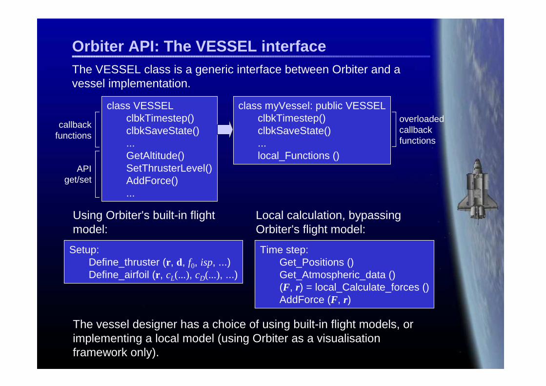
Orbiter�API:�The�VESSEL�interfaceThe�VESSEL�class�is�a�generic�interface�between�Orbiter�and�a�vessel�implementation.���
class�VESSELclbkTimestep()clbkSaveState()...GetAltitude()SetThrusterLevel()AddForce()...
class�myVessel:�public�VESSELclbkTimestep()clbkSaveState()...local_Functions�()
callback�functions
API�get/set
overloadedcallback�functions
Using�Orbiter's�built-in�flight�model:
Setup:Define_thruster�(r,�d,�f0,�isp,�...)Define_airfoil�(r,�cL(...),�cD(...),�...)
Local�calculation,�bypassing�Orbiter's�flight�model:
Time�step:Get_Positions�()Get_Atmospheric_data�()(F,�r)�=�local_Calculate_forces�()AddForce�(F,�r)
The�vessel�designer�has�a�choice�of�using�built-in�flight�models,�or�implementing�a�local�model�(using�Orbiter�as�a�visualisation�framework�only).

Air-breathing�engines:�scramjet�(1)Scramjet�design�is�an�example�for�implementing�a�feature�entirely�externally�without�native�support�in�the�Orbiter�core.
Ideal�scramjet:�temperature�and�pressure�relationships
∞
−
−
∞∞∞∞
=���
�
�=
==
���
�
�=��
�
� −+=
ppp
pTT
ppTTT
T
TppMTT
eb
ebe
dbdbb
ddd
γγ
γγγ
/)1(
0
)1/(
2
),max(
21
1Diffuser:�isentropic�compression
Combustion�chamber:�isobaric�expansion
Exhaust�nozzle:�isentropic�expansion
Jet�engine�propulsion�thrust�equation:
eeaefa AppvmvmmF )()( ∞∞ −+−+= ���
where������and�������are�the�air�and�fuel�mass�rates,�respectively,�����and���are�the�exhaust�and�freestream�velocities,�and������is�the�exhaust�cross�section.�
am� fm� ev ∞veA

Air-breathing�engines:�scramjet�(2)
Specific�thrust�is�given�by ( ) ∞−+= vvDm
Fe
a
1�
where����������������������is�the�fuel-to-air ratio.af mmD �� /=
bp
db
TcQ
TTD
−−=
/
The�amount�of�fuel�burned�in�the�combustion�chamber�must�be�adjusted�so�that�the�burner�temperature�limit�is�not�exceeded.�This�leads�to�the�following�expression�for�D:
where�Q is�a�fuel-specific�heating�value�and�cp is�the�specific�heat�at�constant�pressure,�given�by�cp =�γR/(γ-1).
The�exhaust�velocity�����can�be�obtained�from�the�energy�balance
ev
2/2eepbp vTcTc +=
0 1 2 3 4 5 6 7 8 90
20
40
60
80
100
120
140
160
180
Mach�number
F�[kN]
Engine�thrus t
Thrust�vs.�Mach�number:
0 1 2 3 4 5 6 7 8 90
0.1
0.2
0.3
0.4
0.5
0.6
0.7
0.8
Mach�number
TSFC�[kg/kJ]
Thrus t-s pecific �fuel�cons umption
TSFC�vs.�Mach�number:

Virtual�3-D�Cockpit• Support�for�3-D�virtual�
cockpit�view
• Head�rotation�improves�situational�awareness
• “Eye-neck”�offset�generates�movement�parallax
• Camera�reference�point�and�rotation�ranges�defined�by�API�calls
• Dynamic�display�updates
• Mouse-operated�instruments
• Viewpoint-corrected�HUD�display
3-D�artwork�courtesy�Roger�Long

New�visual�effects�(1)• Improved�rendering�of�
atmospheric�haze�from�high�altitude
• Additional�configuration�parameters�for�colour�distribution
• Rendering�of�objects�through�atmosphere�layers�is�now�additive.

New�visual�effects�(2)
• Surface�shadow�support�for�structures�and�vessels
• Surface�labels�(launch�sites,�radio�transmitters,�user-defined)

Orbiter�as�a�teaching�tool�(1)
• New�html-based�help�system�(context-sensitive:�scenario- and�vessel-specific).�Can�be�extended�by�3rd party�plugins.
• New�"kiosk�mode"�for�unsupervised�use�in�public�environments�(limited�simulation�run�time,�automatic�scenario�selection).
Help�system:�scenario�instructions
Help�system:�instrument�layout�and�documentation
Help�system:�orbital�mechanics�primer

FlightData�module�logging�atmospheric�data
Orbiter�as�a�teaching�tool�(2)
Data�logging:�flight�data�can�be�extracted�for�analysis�by:• Using�built-in�flight�data�logging�facilities• Writing�custom�data�extraction�modules�using�the�API�interface• New:�Using�DDE�(dynamic�data�exchange)�protocol
Exported�to�a�file�for�offline�analysis
DDE�support:�exporting�flight�data�to�MATLAB
Summary• Orbiter�is�an�accessible�tool�for�atmospheric,�orbital�and�
interplanetary�space�flight�simulation.• Combining�a�(moderately)�accurate�physics�engine�with�3-D�
rendering,�its�main�application�is�as�an�educational�or�recreational�tool.
• The�programming�interface�(API)�is�a�versatile�way�to�extend�the�core�Orbiter�functionality.�Features�not�natively�supported�by�the�core�can�be�added�by�external�plugins.
• The�API�interface�includes• state�vector�updates�for�celestial�bodies• spacecraft�implementations• instrumentation
• Development�of�the�core�module�is�ongoing,�and�a�growing�set�of�3rd�party�contributions�is�available.

Future�developments
• Improvements�of�the�flight�model�(stability�of�time�integration,micro-drag,�radiation�pressure,�atmospheric�flight�model).
• Damage�and�collision�modelling.• Multi-user�support�(simulation�running�on�server�continuously,�
clients�connect�temporarily).• Elevation�modelling�of�celestial�bodies.
Some�of�the�features�planned�for�future�releases�include:�

Acknowledgements
3-D�Modelling Roger�Long,�Andrew�Farnaby,�Don�Gallagher,�Damir�Gulesich,�David�Sundstrom,�Jason�Benson,�Valerio�Oss
Trajectory�code Duncan�Sharpe�(TransX�transfer�trajectory�plugin)
Vessel�code Radu�Poenaru,�Robert�Conley
Planet�textures James�Hastings-Trew,�Björn�Jonsson,�Dean�Scott,�Philip�Stooke,�Constantine�Thomas,�Robert�Stettner,�James�Williams,�Seth�Hollingsead
The�beta�test�team
The�addon�developer�base
The�sponsors M6.net,�avsim.com

Resources
Orbiter�main�site�(includes�download�links�and�related�sites):www.medphys.ucl.ac.uk/~martins/orbit/orbit.htmlwww.orbitersim.com
Contact:[email protected]
Critique,�suggestions�and�collaborations�are�very�welcome!

<�Orbiter�Demonstration�>