orbit double-acting unit-type 424 diaphragm actuators and
TRANSCRIPT

1
ORBIT
TC9249 96-M-24
Installation, Operation and Maintenance Manual
Orbit Double-ActingUnit-Type
424 Diaphragm Actuatorsand Accessories

2
ORBIT
TC9249 96-M-24
All the information contained in this manual is the exclusive property of Cameron. Any repro-duction or use of the calculations, drawings, photographs, procedures or instructions, either expressed or implied, is forbidden without the written permission of Cameron or its autho-rized agent.
Initial Release 01December 1996
Revision 02December 2012
© 2012 Cameron

3
ORBIT
TC9249 96-M-24
This manual covers the following diaphragm actuator figure numbers:
424120-301 424120-381424121-301 424121-381424122-301 424122-381424123-301 424173-381424124-301 424124-381424125-301 424125-381424126-301 424126-381424627-301 424627-381
For other double-acting unit-type diaphragm actuators see Orbit Manual 83-M-16.
Warning: Bleed pressure from valve and actuator prior to assembly or disassembly operations.
DO NOT REMOVE ANYTHING ON THE VALVE OR ACTUATOR UNLESS SPECIFICALLY INSTRUCTED TO DO SO IN THIS MANUAL, OR WITHOUT FIRST CONSULTING AN ORBIT REPRESENTATIVE. FAILURE TO DO SO COULD RESULT IN INJURY TO PERSONNEL AND DAMAGE TO VALVE, ACTUATOR AND PROPERTY.

4
ORBIT
TC9249 96-M-24
Notes:

5
ORBIT
TC9249 96-M-24
TABLE OF CONTENTSI. Diaphragm Actuator Identification ..........................................................................7
II. Operation of the Diaphragm Actuator ....................................................................7
III. Installation of Valves with 424 Diaphragm Actuator ..............................................8
A. Installation of Valves with Factory Mounted Actuators ..............................8
B. Indicator Plates ..............................................................................................9
C. Field Mounting Instructions ..........................................................................9
1. Assembly Instructions and Mounting Dimensions for Valves .........11 with One Piece Stem Retained Stem Design
2. Assembly Instructions and Mounting Dimensions for ....................12 Two Piece Stem Valves
3. Mounting Dimensions for One Piece Stem Valves ...........................13 Manufactured Prior to 1985
D. Disassembly of 424 Actuator .........................................................................14
E. Assembly of 424 Diaphram Actuator ............................................................16
IV. Double Acting 424 with Snubber .............................................................................19
A. Parts Reference for Figure 14 ........................................................................19
V. Two-Way Manual Mechanism ..................................................................................21
A. Double Acting 424 with Two-Way Parts Reference for Figure 15 ..............21
B. Two-Way Manual Opener and Closer .........................................................21
C. Installation .....................................................................................................22
D. Disassembly ....................................................................................................23
E. Assembly .........................................................................................................23
VI. Lubrication .................................................................................................................23
A. Lubrication of Snubber ..................................................................................23
B. Lubrication Schedule (Except for Snubber Lubrication) ..............................24
C. Recommended Lubricants .............................................................................24
VII. Visual Position Indicator ............................................................................................24

6
ORBIT
TC9249 96-M-24
Notes:

7
ORBIT
TC9249 96-M-24
I. DIAPHRAGM ACTUATOR IDENTIFICATION
Proper identification of the actuator figure number is needed for installation or repair pur-poses. The actuator figure number is stamped on the valve/actuator nameplate. See figure 1 for nameplate identification.
II. OPERATION OF THE DIAPHRAGM ACTUATOR
The Orbit Unit Diaphragm Actuator is a linear, double-acting actuator used for remote opera-tion of Orbit valves. Operation of the valve is accomplished by applying gas pressure to either the opening or closing side of the diaphragm.
Note: Operating pressures are stamped on the nameplate for the actuator and valve. The op-erating pressure for the actuator is 45-50 psig unless otherwise stamped. See figure 1.
Warning: Avoid bleeding pressure from the actuator while the valve is in service. Loss of pres-sure could cause the valve to inadvertently open or close. If actuator pressure is lost, verify that the valve is in the desired position.
Integral Snubber: Double Acting 424 actuators are always supplied with an integral snubber that is situated on top of the upper diaphragm case.
Manual Two-Way Mechanism (Optional): The top mounted manual two-way mechanism is used to lock the valve in either the open or closed position and to manually open or close the valve when operation cannot be accomplished with gas pressure. Rotation of the handwheel in a clockwise direction closes the valve and rotation in the counterclockwise direction opens the valve. Prior to operation with gas pressure, the handwheel must be locked in the neutral position – rotate handwheel counterclockwise until valve is open. After valve is open, rotate handwheel clockwise and move the weather shield up until the lower edge of the shield is flush with the top of neutral position groove in the jack nut housing. When valve is in neutral position, engage the locking pin.

8
ORBIT
TC9249 96-M-24
III. INSTALLATION OF VALVES WITH 424 DIAPHRAGM ACTUATOR
The diaphragm actuator is normally mounted on the valve at the factory, but may be field mounted.
Note: Two lifting lugs are provided on the diaphragm case. These must be used when han-dling the actuator to prevent damage to equipment and injury to personnel.
A. Installation of Valves with Factory Mounted Actuators
1. Install the valve/actuator package in the pipeline so the PREFERRED PRESSURE END will be applied to the higher pressure when the valve is closed. See figure 2.
2. Connect the open and close supply pressure lines (3/8 NPT connections). See figure 3 for location of these connections.

9
ORBIT
TC9249 96-M-24
Warning: A regulated gas supply with flow controls on each line (open and close) should be used to regulate operating speed and to prevent damage to the equipment. If optional instrumentation is provided, see the applicable Suggested Piping Ar-rangement drawing for connection to the gas pressure supply.
3. Read nameplates, warning tags, and any instruction tags before pressuring the actuator.
4. Check operation of actuator. This can be accomplished by observing that the point-er on the VPI is over the bright band on the indicator plates (pre-set at factory) in the open and closed position. See figure 4.
Note: On field mounted actuators, the open and closed indicator plates must be adjusted. See the Indicator Plate section.
5. Check to make sure snubber is full of snubber grease. See Lubrication section.
6. Lubricate actuator (see “Lubrication” section) if it has been stored for more than three (3) months or if it has been repaired.
7. Installation is complete.
B. Indicator Plates
Refer to figure 4.
1. Cycle the valve to the full open or closed position.
2. Attach the corresponding plate with self-tapping screws so the pointer is over the bright band.
3. To determine if the valve is achieving full travel, observe the position of the core in the valve bore.
Note: During the life of the valve, the stem travel will increase, thus causing the “closed” indi-cator plate to require readjustment to compensate for this additional travel.
C. Field Mounting Instructions
Conversion of handwheel valves to actuator operated valves and mounting actuators on valves with adapter flange installed on valve.

10
ORBIT
TC9249 96-M-24
The actuator mounting procedure is dependent upon the valve model. The valve model is identified by the serial number stamped on the valve nameplate, valve/actuator name-plate, and valve body. See figure 5.
In order to determine the exact valve model onto which the actuator will be mounted, contact your local Cameron representative with the valve serial number. Then follow the corresponding instructions contained in this manual.
Warning: Be certain the correct valve model is identified and the correct mounting procedure is followed. Failure to do this could result in personal injury.

11
ORBIT
TC9249 96-M-24
1. Assembly instructions for one piece stem, retained stem design (Post 1985)
a. Screw flange onto bonnet until assembly dimension (1/4 +1/32-0) is achieved and (2) bolt holes in flange are aligned with centerline of valve bore. (Do not apply lubricants to threads.)
b. Place adapter plate on valve. Check assembly clearance (1/32) and location of bolt holes with centerline of valve bore and adjust if necessary.
c. Install (4) 1/2-13 bolts/studs and nuts and torque to 60 ft-lb, in 20 ft-lb incre-ments, using a criss-cross pattern.
d. Place cup-point punch (1A-Z-3904) in each set screw hole and strike sharply with hammer.
e. Install set screws (1A-S-7082) and tighten securely.
f. Weld flange to bonnet with 1/4 x 3/4 x 3/4 bridge.
Note: Orbit recommends welding the flange to the bonnet, but under normal operating con-ditions, the flange is adequately locked in position if assembly instructions 1 through 5 are carefully followed.
Mounting Dimensions for 424 Diaphragm Actuators onRetained Stem, One Piece Stem Valves

12
ORBIT
TC9249 96-M-24
2. Assembly instructions for two piece stem valves
a. Place adapter plate on integral bonnet flange of valve. Check assembly clear-ance (1/32).
b. Install (4) 1/2”-13 bolts/studs and nuts and torque to 60 ft-lb, in 20 ft-lb incre-ments, using a criss-cross pattern.
Mounting Dimensions for 424 Diaphragm Actuators on Valves withSerial Number Prefix beginning with “H”

13
ORBIT
TC9249 96-M-24
3. Mounting dimensions for 424 diaphragm actuators on previous valve models one piece stem valves manufactured prior to 1985
Warning: Lock Ring is mandatory to lock the adapter flange in place, provide the open-posi-tion stem stop during operation, and assure stem retention in the event the actua-tor is subsequently removed without depressuring the valve. INJURY CAN RESULT from failure to provide this stem retention for one-piece stem valves.

14
ORBIT
TC9249 96-M-24
D. Disassembly of 424 Snubbed Actuator
The following procedure describes how the actuator can be completely disassembled. In order to completely disassemble actuator, it should be removed from valve. This opera-tion will be necessary only in the event internals of the actuator need to be inspected or parts such as O-rings and diaphragms need to be replaced. In most cases, as a matter of good practice, the actuator should be completely disassembled, but some cases may war-rant disassembling only as far as is necessary to correct the problem. Preferably, disassem-bly and assembly of this actuator should be done in a shop that has a clean work bench where sand, grit or other debris can’t get inside and cause damage in the future. The proper tools must be available to perform the work.
Refer to Double Acting with Snubber - Parts Reference
1. The actuator must be in the full-up (open) position.
Caution: Remove the line pressure from the valve before disassembly. Be sure that all pressure has been bled off the actuator.

15
ORBIT
TC9249 96-M-24
2. Remove actuator mounting bolts and nuts.
3. Rotate actuator clockwise to unscrew it from the valve stem.
4. Securely bolt or clamp the actuator to work bench.
5. Cycle snubbed actuator to down (close) position.
6. Remove 1/8 NPT pipe plug (36) from snubber case top (38).
7. Place a container (16 ounce or larger) over the 1/8 NPT hole, cycle the snubbed ac-tuator to the “Up” position, and catch the lubricant.
8. Remove pointer clamp (1), hose clamp (2), and rod boot (3).
9. Loosen two set screws (4), remove collar (5), and remove burrs on VPI rod (8) with fine emery cloth. Remove VPI rod bushing (6) and O-ring (7).
10. Remove hex cap screws (40).
11. Remove snubber case top (38), then remove gasket (39).
12. Unscrew snubber 5/8 hex cap screw (37) 18 turns in order to unscrew the snubber stem (33) from the diaphragm stem assembly (21).
Note: The snubber piston (34) should turn because loctite has been applied to the snubber 5/8 hex cap screw (37) and snubber stem (33). If the snubber piston (34) does not turn when unscrewing the 5/8 hex cap screw (37), the following procedure applies in lieu of steps 14 through 17:
a. Remove snubber 5/8 hex cap screw (37).
b. Remove hex cap screws and nuts (10).
c. Remove snubber case weldment (12) by lifting case up over snubber stem (33).
d. Remove snubber piston (34) from snubber case weldment (12) and then remove step cut piston ring (35).
e. Unscrew snubber stem (33) from diaphragm stem assembly (21).
f. Now follow steps 18 through 24 to complete disassembly of actuator.
13. Remove hex cap screws and nuts (10).
14. Remove snubber case weldment (12) from actuator assembly.
15. Unscrew 5/8 hex cap screw (37) from snubber stem (33) and then remove both items from snubber case weldment (12).
16. Remove snubber piston (34) and stem cut piston ring (35).
17. Remove retaining ring (27) and snubber floating piston (28). Then remove O-rings (30) and quad ring (29) from snubber floating piston (28).
18. Remove lock nut (13), support plates (9), diaphragm plates (14), O-rings (15), dia-phragm (16), and VPI rod assembly (8).
19. Unscrew VPI assembly (8) from support plate (9).
20. Remove retaining ring (17) with a screwdriver.
21. Remove diaphragm stem assembly (21) and flat key (22).
22. Disassembly is complete.
Note: Throttle screw (31), sealing lockout (32) and lube fittings (41) are not removed unless damaged.

16
ORBIT
TC9249 96-M-24
23. Clean and inspect parts.
Note: Replace O-rings and diaphragm whenever the actuator is disassembled. Inspect the dia-phragm thoroughly if it is not replaced.
E. Assembly of 424 Diaphragm Actuator
Refer to Double Acting with Snubber - Parts Reference (Lubricate at points noted in fig-ure).
1. Install flat key (22) into diaphragm stem assembly (21) and install into lower dia-phragm case (23).
Note: Assembly is easier if a small block is placed under the diaphragm stem assembly to slightly lift it until the snubber stem (33) is tightened.
2. Install O-rings (19 and 20) into sealing gland (18).
3. Slip sealing gland (18) with O-rings over the diaphragm stem assembly (21) into recess in lower diaphragm case. It may be necessary to tap it into place.
4. Install retaining ring (17) into ring groove in lower diaphragm case. Be certain the ring fully seats into ring groove.
5. Screw alignment tool 1A-Z-2886 hand-tight into one of the support plates (9) such that the tool sticks down.
6. Install support plate with alignment tool so that the alignment tool drops through the hole for the VPI rod bushing.
7. Install diaphragm plate (14) such that the center chamfered hole faces up and in-stall lower O-ring (15).
Note: Be careful not to damage the O-ring when slipping it over the diaphragm stem threads (21).
8. Install diaphragm (16) and upper O-ring (15).
9. Install upper diaphragm plate (14) such that the center chamfered hole faces down (fits over O-ring). Install support plate (9).
10. Orient the diaphragm (16) with the holes in the lower diaphragm case (23). Screw lock nut (13) on diaphragm stem assembly (21) and torque to 50 ft-lb. Screw snub-ber stem (33) on diaphragm stem assembly (21) and torque to 50 ft-lb.
11. Install quad ring (29) and O-ring (30) in snubber floating piston (28).
12. Install snubber floating piston (28) and retaining ring (27) in snubber case weld-ment (12). Install the upper diaphragm case (12) with hex cap screws and nuts (10) using a criss-cross method of tightening. Align air inlet connection on upper dia-phragm case (12) with air inlet connection on lower diaphragm case (23).
13. Remove alignment tool 1A-Z-2886 and install the VPI rod assembly (8) using slot in rod end.
14. Remove burrs on VPI rod (8) with emery cloth. Install O-ring (7) into VPI rod bushing (6), slip onto VPI rod assembly (8), and tighten securely into lower diaphragm case.

17
ORBIT
TC9249 96-M-24
15. Slip the hose clamp (2) over one end of the rod boot (3) and the pointer clamp (1) over the other end. Install and tighten the hose clamp and rod boot over the VPI rod bushing (6).
16. Install the collar (5) onto the end of the VPI rod assembly (8) with the set screws (4).
17. Slip the end of the rod boot (3) over the collar (5) and tighten the pointer clamp (1).
Note: Set the assembly dimension before tightening. The rod boot to bottom of collar is 3/4 inch and the bottom of the pointer clamp to bottom of rod boot is 1/8 inch.
18. Install throttle screw (31), sealing lockout (32), and lube fitting (25 and 41) if re-moved or missing.
19. Install step cut piston ring (35) on snubber piston (34), and place snubber piston (34) on top of snubber stem (33).
20. Screw on snubber 5/8 hex cap screw (37) and torque to 50 ft-lb.
21. Place gasket (39) on top of snubber case weldment. Make sure 3/8 diameter hole in gasket is aligned over grease hole in snubber case weldment (12).
22. Install snubber case top (38) with hex cap screws (40). Make sure 1/8 NPT hole is aligned over throttle screw (31) and torque to 70 ft-lb.
Note: Snubber grease only can now be added to the snubber as described in the lubrication section or after the actuator is mounted on the valve.
23. Install 1/8 NPT pipe plug (36) if snubber grease has not been added and will not be added right after the snubbed actuator is mounted onto the valve.
24. The actuator is now complete and ready to mount onto the various model valves.
Note: After mounting to a valve, the actuator should be lubricated as described in the lubrica-tion section. If the actuator is not going into service immediately, the thread protectors (24) should be installed into the gas line connections.

18
ORBIT
TC9249 96-M-24

19
ORBIT
TC9249 96-M-24
IV. DOUBLE ACTING 424 WITH SNUBBER
A. Parts Reference for Figure 14
Item Description Item Description
1 Pointer Clamp 22 Flat Key
2 Hose Clamp 23 Lower Diaphragm Case
3 Rod Boot 24 Bushing 1/2” NPT x 3/8 NPT
4 Set Screw 25 Lube Fitting
5 Collar 26 Relief Fitting
6 VPI Rod Bushing 27 Snubber Retaining Ring
7 O-ring 28 Snubber Floating Piston
8 VPI Rod Assembly 29 Quad Ping
9 Support Plates 30 O-ring
10 Hex Cap Screw & Nut 31 Throttle Screw
11 Lifting Lug 32. Sealing Locknut
12 Upper Diaphragm Case 33 Snubber Stem
13 Lock Nut 34 Snubber Piston
14 Diaphragm Plate 35 Step Cut Piston Ring
15 O-ring 36 Pipe Plug - 1/8 NPT
16 Diaphragm 37 Hex Cap Screw
17 Retaining Ring 38 Snubber Case Top
18 Sealing Gland 39 Gasket
19 O-ring 40 Hex Cap Screw
20 O-ring 41 Hydraulic lube fitting
21 Diaphragm Stem Assembly

20
ORBIT
TC9249 96-M-24
21
ORBIT
TC9249 96-M-24
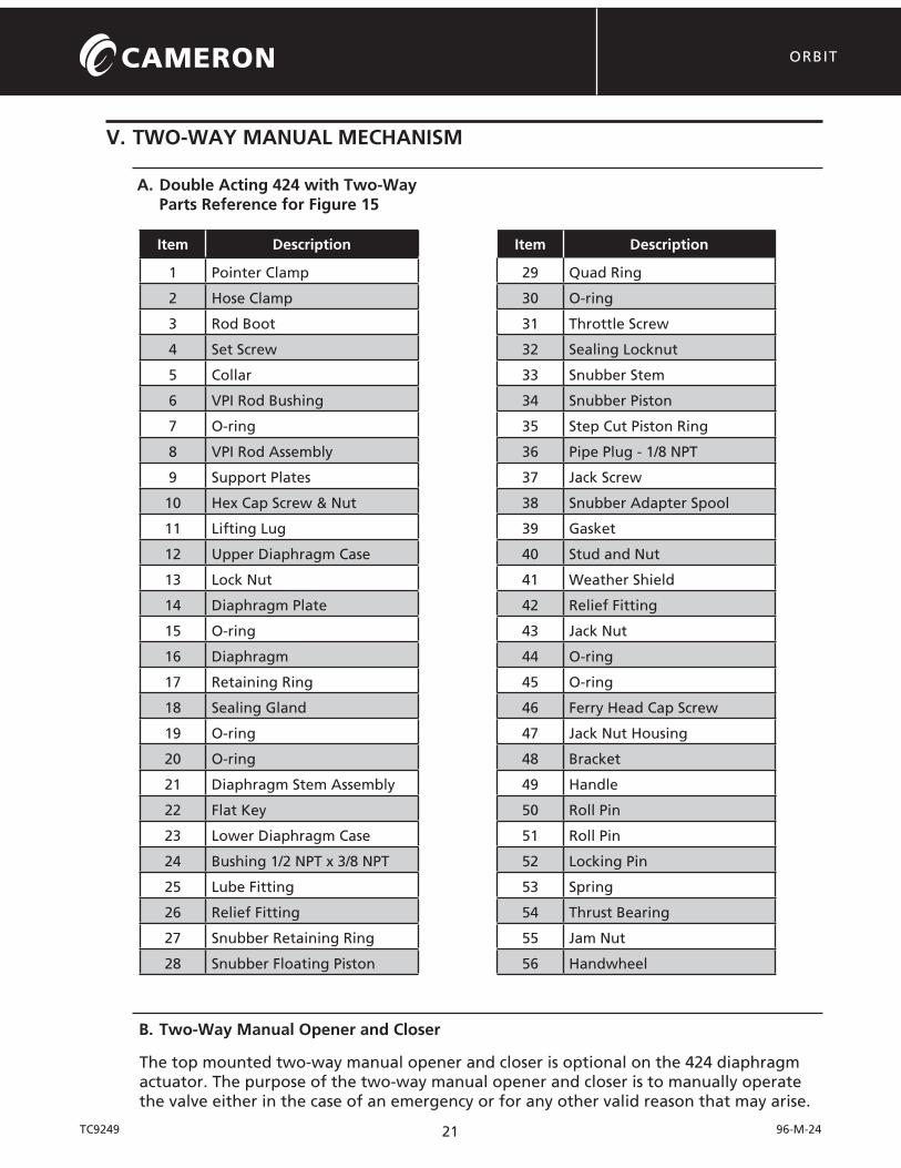
V. TWO-WAY MANUAL MECHANISM
A. Double Acting 424 with Two-Way Parts Reference for Figure 15
Item Description Item Description
1 Pointer Clamp 29 Quad Ring
2 Hose Clamp 30 O-ring
3 Rod Boot 31 Throttle Screw
4 Set Screw 32 Sealing Locknut
5 Collar 33 Snubber Stem
6 VPI Rod Bushing 34 Snubber Piston
7 O-ring 35 Step Cut Piston Ring
8 VPI Rod Assembly 36 Pipe Plug - 1/8 NPT
9 Support Plates 37 Jack Screw
10 Hex Cap Screw & Nut 38 Snubber Adapter Spool
11 Lifting Lug 39 Gasket
12 Upper Diaphragm Case 40 Stud and Nut
13 Lock Nut 41 Weather Shield
14 Diaphragm Plate 42 Relief Fitting
15 O-ring 43 Jack Nut
16 Diaphragm 44 O-ring
17 Retaining Ring 45 O-ring
18 Sealing Gland 46 Ferry Head Cap Screw
19 O-ring 47 Jack Nut Housing
20 O-ring 48 Bracket
21 Diaphragm Stem Assembly 49 Handle
22 Flat Key 50 Roll Pin
23 Lower Diaphragm Case 51 Roll Pin
24 Bushing 1/2 NPT x 3/8 NPT 52 Locking Pin
25 Lube Fitting 53 Spring
26 Relief Fitting 54 Thrust Bearing
27 Snubber Retaining Ring 55 Jam Nut
28 Snubber Floating Piston 56 Handwheel
B. Two-Way Manual Opener and Closer
The top mounted two-way manual opener and closer is optional on the 424 diaphragm actuator. The purpose of the two-way manual opener and closer is to manually operate the valve either in the case of an emergency or for any other valid reason that may arise.

22
ORBIT
TC9249 96-M-24
Two-way manual operators have an instruction plate. See figure 16.
The following details the instructions for the two-way manual opener and closer:
1. To close the valve manually when valve is open and handwheel is locked in neutral position, first disengage the locking pin so handwheel will turn, then rotate hand-wheel in clockwise direction until valve is closed. If the valve is not in the neutral position but locked in the open position, disengage the locking pin and rotate clockwise as mentioned before. The difference here is that the handwheel has to be rotated approximately 26 turns clockwise for the jack nut to move up and shoulder on the top of the jack nut housing before the jack screw will start moving down to close the valve. When valve is closed, engage the locking pin.
2. To open the valve manually when valve is closed and handwheel is locked in the neutral position, first disengage the locking pin so handwheel will turn, then rotate handwheel in counterclockwise direction until valve is open. If the valve is not in the neutral position but locked in the closed position, disengage the locking pin and rotate counterclockwise. Again, the handwheel has to be rotated approximate-ly 26 turns counterclockwise for the jack nut to move down and shoulder on the bearing ring before the jack screw will start moving up to open the valve. When valve is open, engage the locking pin.
3. For air operation the handwheel must be in the neutral position. Rotate handwheel counterclockwise until valve is open as discussed in step 2 above. After valve is open, rotate handwheel clockwise and move the weather shield up until the lower edge of the shield is flush with the top of neutral position groove in the jack nut housing. When valve is in neutral position, engage the locking pin.
C. Installation
The two-way manual opener and closer is usually installed at the factory; however, there will be times when it has to be installed in the field. After actuator has been placed in a fully open position, be sure all pressure has been bled off the actuator. Refer to Double Acting with Snubber - Parts Reference and remove cap screws (40), and take snubber case top (38) off. Remove cap screw (37).

23
ORBIT
TC9249 96-M-24
Now the actuator is ready for installation of the two-way manual opener and closer. With reference to Two-Way Manual Mechanism - Parts Reference, rotate the jack screw (37) (left hand Acme thread) to remove it from the two-way manual mechanism. With the jack screw removed, screw it on to the snubber stem (33) through the snubber piston (34); torque to 50 ft-lb. Screw in studs (40) until 1-5/8” is left exposed. Note that hole in gasket (39) lines up with hole in snubber above throttle screw (31). With gasket (39) in place, screw the two-way manual mechanism assembly on to the jack screw (37). Stop at about 1/4” clearance between the studs and the snubber adapter spool (38); line up the hole in the snubber adapter spool (38) with the hole in the gasket. Disengage the locking pin handle (49) and turn the handwheel on the two-way counter clockwise (to lower the two-way straight down on the studs). When the lower flange of the snubber adapter spool (38) is touching the snubber, install nuts (40) and torque to 70 ft-lb. Set the handwheel in neutral position for air operation by using procedure in figure 16. Refill the snubber using procedure Lubrication of Snubber. Install pipe plug (36).
D. Disassembly
Refer to Two-Way Manual Mechanism - Parts Reference, being sure all pressure has been bled off the 424 diaphragm actuator and there is not any pressure trapped inside of the weather shield (41) by checking to see if relief fitting (42) is plugged. After these pre-cautions have been taken, back off the jam nut (55) and remove handwheel (56). Next, remove ferry head cap screw (46) and take off the locking pin assembly which consists of bracket (48), handle (49), roll pin (50 and 51), locking pin (52), and spring (53). The locking pin assembly need not be disassembled any further unless there is obvious damage to it. Now slip the weather shield (41) off and inspect O-ring (44). Replace O-ring if damaged. Relief fitting (42) need not be removed unless it is damaged and has to be replaced. Next, remove remaining ferry head cap screws (46) and take the jack nut housing (47) off the actuator by lifting straight up. Remove the jack nut (43) by rotating clockwise.
Note: Before removing snubber adapter spool: If disassembly of the snubber is necessary, remove the lubrication from the snubber by steps 6 through 8 of Disassembly of 424 Diaphragm Actuator.
Remove the snubber adapter spool (38) by removing nuts (40). A wrench flat is accessible on the jack screw (37) to allow removal. Upon inspection of the thrust bearings (54) in the jack nut, any damage will require replacement.
E. Assembly
Reassemble the two-way manual by reversing the foregoing disassembly procedure and making sure the actuator is in the full open position. Coat all O-rings, O-ring grooves, in-side surface of weather shield, outside surface of jack nut and the external threads of the jack screw with a lubricant such as Lubriplate LM123-006. Apply anti seize lubricant to the threads on the ferry head cap screws before inserting them in the bolt holes. Apply anti sieze lubricant to the threads for the jam nut that holds the handwheel.
VI. LUBRICATION
A. Lubrication of Snubber
1. Remove 1/8 NPT pipe plug and open throttle screw.

24
ORBIT
TC9249 96-M-24
Important: Actuator/snubber must be in the full-open (up) position when filling snubber with grease.
2. Fill snubber with synthetic diester based grease (such as Lonestar lubricants LS-62) until it begins to come out of 1/8 NPT hole. Close throttle screw and fill until lubri-cant comes out with no air pockets.
Note: It is advisable to hold a container over the 1/8 NPT hole in order to avoid having lubri-cant “spit” out.
3. Install 1/8 NPT pipe plug after there is no evidence of air in the snubber. Make sure sealing locknut is tight.
4. If valve jumps, repeat fill procedure.
5. Adjust throttle screw to obtain desired valve cycling speed. If not able to monitor desired cycling speed, then back off approximately 1/2 turn.
B. Lubrication Schedule (Except for Snubber Lubrication)
Note: The snubber is self lubricated and does not require periodic maintenance.
1. A minimum of once a year
2. Every three months if the actuator/valve combination is operated infrequently (once a day or less)
3. Every 1,000 cycles if actuator/valve combinations operated more than 10 times a day
4. Every 500 cycles if the actuator/valve combination is operated in corrosive or other severe service and operated more than 10 times a day
5. Any time the actuator or valve is serviced for a leak
6. Any time the actuator has been stored for more than three months and then put into service (even if the actuator has never been used)
Note: Actuators that are mounted on high temperature valves, +600º F (316º C) and above, should be lubricated twice as often as recommended above.
C. Recommended Lubricants
1. Lubriplate “low temp” grease or equivalent is recommended for pumping into grease fittings. (Excludes snubber and snubber manual closer).
2. Anti-seize compound is recommended for use on external threads.
3. Lubriplate “LM 123-006” lubricant or equivalent is recommended for use on O-rings or surfaces that rub against O-rings. (Excludes O-rings in snubber and in upper dia-phragm case).
4. Diester base grease is required for the snubber, snubber manual two-way, snubber O-rings, and upper diaphragm case O-ring.
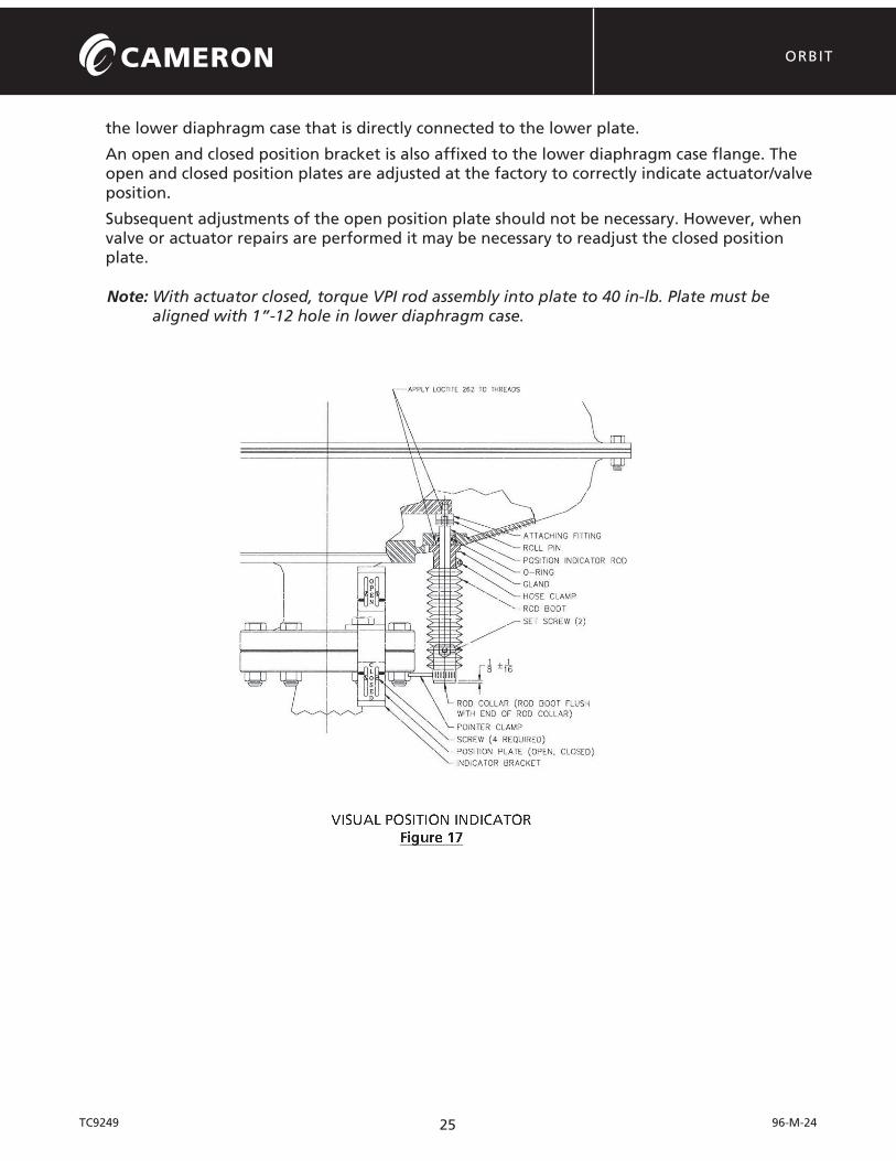
VII. VISUAL POSITION INDICATOR
Every current production diaphragm actuator has a visual position indicator rod located on
25
ORBIT
TC9249 96-M-24
the lower diaphragm case that is directly connected to the lower plate.
An open and closed position bracket is also affixed to the lower diaphragm case flange. The open and closed position plates are adjusted at the factory to correctly indicate actuator/valve position.
Subsequent adjustments of the open position plate should not be necessary. However, when valve or actuator repairs are performed it may be necessary to readjust the closed position plate.
Note: With actuator closed, torque VPI rod assembly into plate to 40 in-lb. Plate must be aligned with 1”-12 hole in lower diaphragm case.

26
ORBIT
TC9249 96-M-24
Notes: