orangerx 3+axis) flight) stabilizer) v3 with spektrum/jr ... · pdf filefeatures:!...
TRANSCRIPT
OrangeRX 3-‐Axis Flight Stabilizer V3 with Spektrum/JR
DSM2 Compatible 6Ch 2.4GHz Receiver (V-‐tail/Delta/AUX)
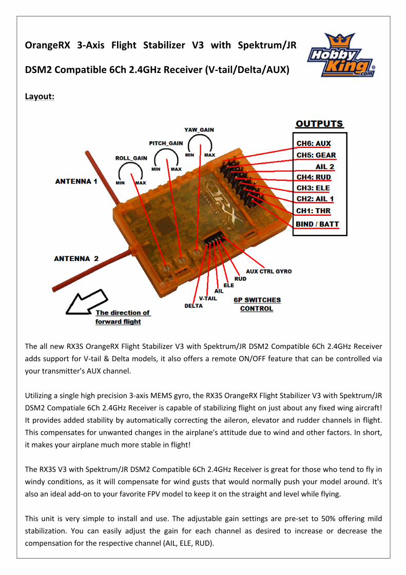
Layout:
The all new RX3S OrangeRX Flight Stabilizer V3 with Spektrum/JR DSM2 Compatible 6Ch 2.4GHz Receiver adds support for V-‐tail & Delta models, it also offers a remote ON/OFF feature that can be controlled via your transmitter's AUX channel. Utilizing a single high precision 3-‐axis MEMS gyro, the RX3S OrangeRX Flight Stabilizer V3 with Spektrum/JR DSM2 Compatiale 6Ch 2.4GHz Receiver is capable of stabilizing flight on just about any fixed wing aircraft! It provides added stability by automatically correcting the aileron, elevator and rudder channels in flight. This compensates for unwanted changes in the airplane's attitude due to wind and other factors. In short, it makes your airplane much more stable in flight! The RX3S V3 with Spektrum/JR DSM2 Compatible 6Ch 2.4GHz Receiver is great for those who tend to fly in windy conditions, as it will compensate for wind gusts that would normally push your model around. It's also an ideal add-‐on to your favorite FPV model to keep it on the straight and level while flying. This unit is very simple to install and use. The adjustable gain settings are pre-‐set to 50% offering mild stabilization. You can easily adjust the gain for each channel as desired to increase or decrease the compensation for the respective channel (AIL, ELE, RUD).
Features: • Capable of stabilizing flight on just about any fixed wing aircraft (including V-‐tail/Delta models) • Spektrum/JR DSM2 compatible 6Ch 2.4GHz Receiver • Remote ON/OFF feature that can be controlled via your transmitter's AUX channel • Supports 3D flight without undermining stability • Independent gyro gain adjustment for aileron, elevator and rudder • Easy-‐to-‐access gyro reversing switches on front of unit • Compact and light weight design Specs: Size: 53x34x14mm Weight: 15g IC: Atmega168PA Gyro: 3-‐Axis MEMS Receiver: Spektrum/JR DSM2 Compatible 6Ch 2.4GHz Input Voltage: 4.8-‐6.0V Signal from Receiver: 1520us Signal to Servo: 1520us
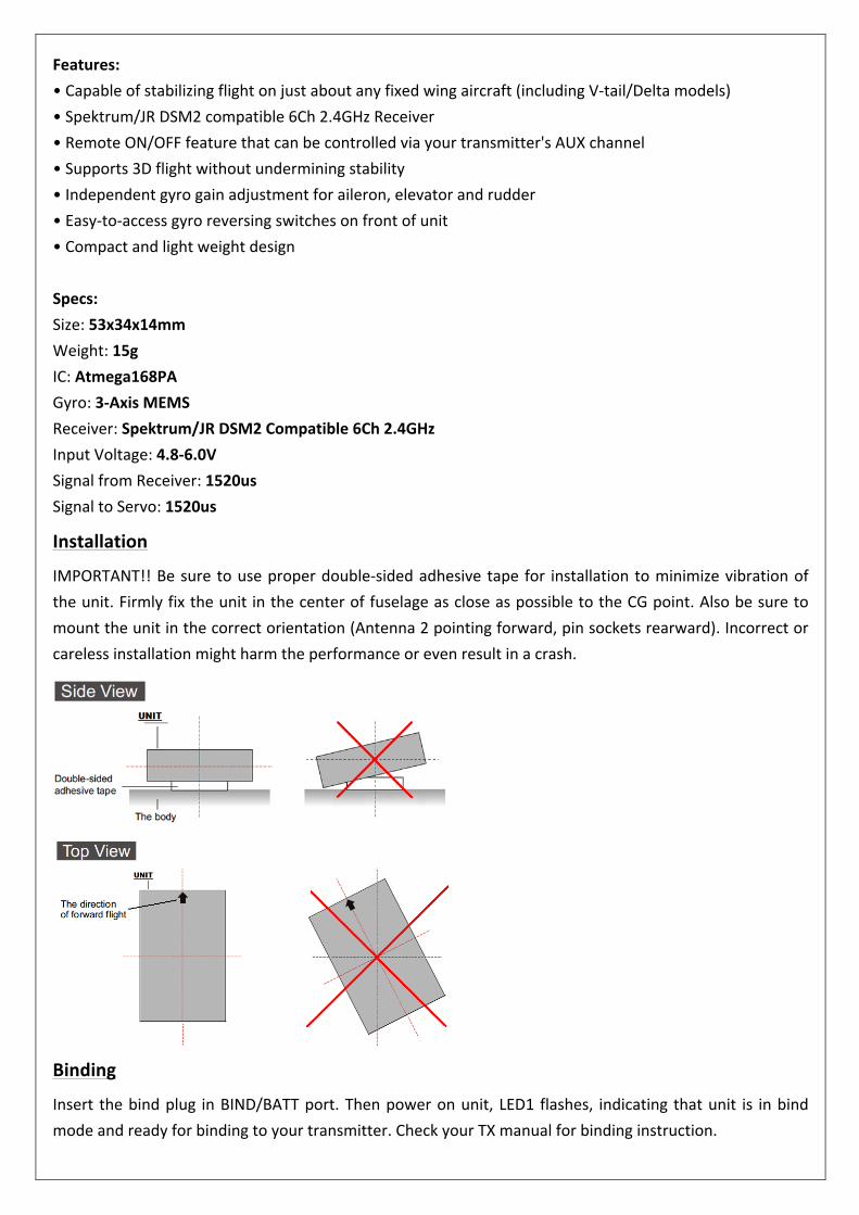
Installation
IMPORTANT!! Be sure to use proper double-‐sided adhesive tape for installation to minimize vibration of the unit. Firmly fix the unit in the center of fuselage as close as possible to the CG point. Also be sure to mount the unit in the correct orientation (Antenna 2 pointing forward, pin sockets rearward). Incorrect or careless installation might harm the performance or even result in a crash.
Binding
Insert the bind plug in BIND/BATT port. Then power on unit, LED1 flashes, indicating that unit is in bind mode and ready for binding to your transmitter. Check your TX manual for binding instruction.
Wiring
Connect the servos (Aileron, Elevator, Rudder) to the pins AIL 1 (AIL 2 is reversed direction of AIL 1), ELEV, RUDD accordingly. When connecting, you should pay attention to the colors of wires to avoid plugging in reversed. The WHITE (or YELLOW) signals wires should be connected corresponding to the inner pins on the unit, the RED (VCC) wires to the center pins, and the BLACK (GND) wires to the pins on the outer edge of the unit.
Gyro Gain Adjustment
This unit has three trimmer potentiometers to control the gyro gain of roll, pitch, and yaw. Turn clockwise to increase the gain, or turn anticlockwise to decrease. The adjustment becomes effective immediately and no need to re-‐power up. [Note: For your safety, please DO NOT adjusting gain while propellers in motion.]
6P Switches Control Setting
1) AUX_CTRL control Gyro
With this switch in the left side (near the pin sockets), gyro function will be always ON and AUX_CTRL control Gyro function will be turned OFF. When this switch is switched to the right side, the gyro function will be controlled by the AUX signal. With this function, the AUX signal within 1.7ms and 2.1ms period will disable Gyro function, in other words, any other signal value will activate the Gyro function.
2) RUD
With this switch in the left side (near the pin sockets), the rudder servo will work in normal mode. When this switch is switched to the right side, the rudder servo will work in reversed mode.
3) ELE
With this switch in the left side (near the pin sockets), the elevator servo will work in normal mode. When this switch is switched to the right side, the elevator servo will work in reversed mode.
4) AIL
With this switch in the left side (near the pin sockets), the aileron servo will work in normal mode. When this switch is switched to the right side, the aileron servo will work in reversed mode.
5) V-‐tail
This switch is used to select the unit working in V-‐tail airplane mode. Just switch the switch to the right side and the V-‐tail mode will be selected. LED2 will flash in a 1sec ON and 1sec OFF cycle.
6) Delta
This switch is used to select the unit working in Delta airplane mode. Just switch the switch to the right side and the Delta mode will be selected. LED2 will be flash in a 0.3sec ON and 2.7sec OFF cycle.
(Note: if both V-‐tail and Delta switches are selected or unselected, unit will function in Normal mode. LED2 will be lit solid.)
Notice for the First Use
1. Please carefully check the connecting directions of each channel, make sure that the remote control switch stays OFF, and the DIP switches are set in the correct position.
2. Check the transmitter controls to make sure they are working. 3. Check that the LED indication is correct based on the selected airplane type. 4. Check the signal output of the radio transmitter. First, check if the aileron, elevator, and rudder are
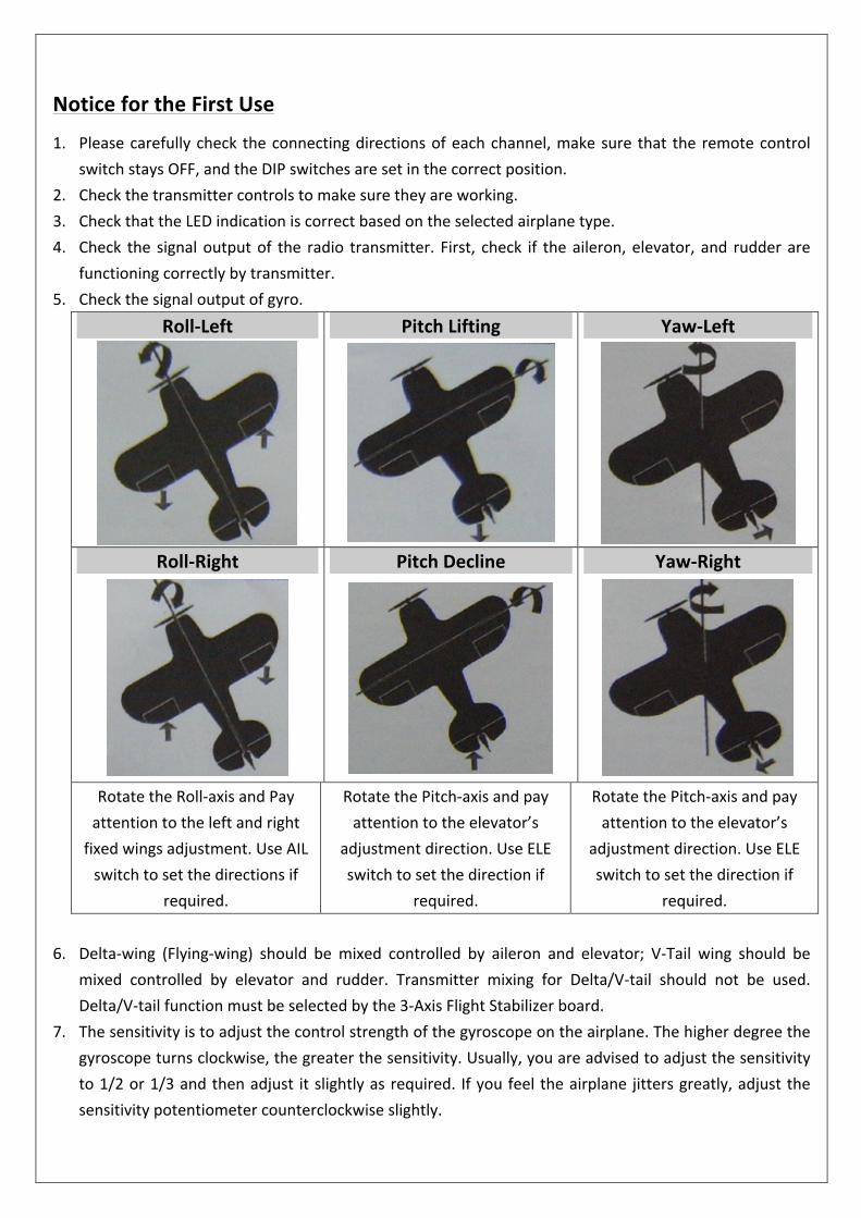
functioning correctly by transmitter. 5. Check the signal output of gyro.
Roll-‐Left
Pitch Lifting
Yaw-‐Left
Roll-‐Right
Pitch Decline
Yaw-‐Right
Rotate the Roll-‐axis and Pay attention to the left and right fixed wings adjustment. Use AIL switch to set the directions if
required.
Rotate the Pitch-‐axis and pay attention to the elevator’s
adjustment direction. Use ELE switch to set the direction if
required.
Rotate the Pitch-‐axis and pay attention to the elevator’s
adjustment direction. Use ELE switch to set the direction if
required. 6. Delta-‐wing (Flying-‐wing) should be mixed controlled by aileron and elevator; V-‐Tail wing should be
mixed controlled by elevator and rudder. Transmitter mixing for Delta/V-‐tail should not be used. Delta/V-‐tail function must be selected by the 3-‐Axis Flight Stabilizer board.
7. The sensitivity is to adjust the control strength of the gyroscope on the airplane. The higher degree the gyroscope turns clockwise, the greater the sensitivity. Usually, you are advised to adjust the sensitivity to 1/2 or 1/3 and then adjust it slightly as required. If you feel the airplane jitters greatly, adjust the sensitivity potentiometer counterclockwise slightly.