oracle maxrep for san hardware guide · oracle maxrep for san hardware guide ... install the slide...
TRANSCRIPT

Oracle MaxRep for SAN
Hardware Guide
Part Number E53316-03Oracle MaxRep for SAN release 3.0
2015 October

Copyright © 2005, 2015, Oracle and/or its affiliates. All rights reserved.
This software and related documentation are provided under a license agreement containing restrictions onuse and disclosure and are protected by intellectual property laws. Except as expressly permitted in yourlicense agreement or allowed by law, you may not use, copy, reproduce, translate, broadcast, modify,license, transmit, distribute, exhibit, perform, publish, or display any part, in any form, or by any means.Reverse engineering, disassembly, or decompilation of this software, unless required by law forinteroperability, is prohibited.
The information contained herein is subject to change without notice and is not warranted to be error-free. Ifyou find any errors, please report them to us in writing.
If this is software or related documentation that is delivered to the U.S. Government or anyone licensing it onbehalf of the U.S. Government, then the following notice is applicable:
U.S. GOVERNMENT END USERS: Oracle programs, including any operating system, integrated software,any programs installed on the hardware, and/or documentation, delivered to U.S. Government end users are"commercial computer software" pursuant to the applicable Federal Acquisition Regulation and agency-specific supplemental regulations. As such, use, duplication, disclosure, modification, and adaptation of theprograms, including any operating system, integrated software, any programs installed on the hardware,and/or documentation, shall be subject to license terms and license restrictions applicable to the programs.No other rights are granted to the U.S. Government.
This software or hardware is developed for general use in a variety of information management applications.It is not developed or intended for use in any inherently dangerous applications, including applications thatmay create a risk of personal injury. If you use this software or hardware in dangerous applications, then youshall be responsible to take all appropriate fail-safe, backup, redundancy, and other measures to ensure itssafe use. Oracle Corporation and its affiliates disclaim any liability for any damages caused by use of thissoftware or hardware in dangerous applications.
Oracle and Java are registered trademarks of Oracle and/or its affiliates. Other names may be trademarks oftheir respective owners.
Intel and Intel Xeon are trademarks or registered trademarks of Intel Corporation. All SPARC trademarks areused under license and are trademarks or registered trademarks of SPARC International, Inc. AMD,Opteron, the AMD logo, and the AMD Opteron logo are trademarks or registered trademarks of AdvancedMicro Devices. UNIX is a registered trademark of The Open Group.
This software or hardware and documentation may provide access to or information about content, products,and services from third parties. Oracle Corporation and its affiliates are not responsible for and expresslydisclaim all warranties of any kind with respect to third-party content, products, and services unlessotherwise set forth in an applicable agreement between you and Oracle. Oracle Corporation and its affiliateswill not be responsible for any loss, costs, or damages incurred due to your access to or use of third-partycontent, products, or services, except as set forth in an applicable agreement between you and Oracle.
Documentation Accessibility
For information about Oracle's commitment to accessibility, visit the Oracle Accessibility Program website at http://www.oracle.com/pls/topic/lookup?ctx=acc&id=docacc.
Access to Oracle Support
Oracle customers that have purchased support have access to electronic support through My OracleSupport. For information, visit http://www.oracle.com/pls/topic/lookup?ctx=acc&id=info or visit http://www.oracle.com/pls/topic/lookup?ctx=acc&id=trs if you are hearing impaired.
ContentsList of Figures..............................................................................................................................9
List of Tables .............................................................................................................................19
Preface ......................................................................................................................................20Related Documentation .......................................................................................................20Oracle Resources ................................................................................................................20
Chapter 1: Introduction to Oracle MaxRep Replication for SAN ...............................................21Oracle MaxRep for SAN ......................................................................................................21Oracle MaxRep for SAN Replication Engine .......................................................................22Supported HBAs ..................................................................................................................24
Chapter 2: Configure the Ports..................................................................................................26Ports on the Replication Engine...........................................................................................26HBA Slot and Port Usage for Supported Configurations .....................................................27FC Configuration..................................................................................................................27FC Configuration Using RJ45 Connectors...........................................................................28FC Configuration Using SFP or Optical Connectors............................................................29Ethernet Ports ......................................................................................................................30Fibre Channel Ports .............................................................................................................30ILOM Port.............................................................................................................................31Default Network Port Settings..............................................................................................32
Chapter 3: Install the Replication Engine ..................................................................................34Engine Component Unpacking and Inspection....................................................................34Required Tools.....................................................................................................................34Replication Engine Placement in the Rack ..........................................................................35Replication Engine Pre-Installation Checklist ......................................................................36Replication Engine Installation Checklist .............................................................................38Installing the Replication Engine Rails .................................................................................39
Replication Engine Rail Kits ...........................................................................................39Install the Rack Rails for the Replication Engine............................................................40Install the Slide Rails for the Replication Engine ............................................................43Install the Replication Engine CMA ................................................................................48Verify Operation of the Slide Rails and the CMA............................................................51
Insert the Replication Engine Into a Rack............................................................................53
Chapter 4: Cable the Replication Engine ..................................................................................56Cabling Overview for the Replication Engine.......................................................................56Cabling Guidelines for the Replication Engine.....................................................................58Cable the Oracle MaxRep Replication Engine.....................................................................59Oracle MaxRep Replication Engine Wiring Diagrams .........................................................60
3
Chapter 5: Complete the Installation .........................................................................................66Routing Power .....................................................................................................................66Connect Power Cords..........................................................................................................66Power On the Replication Engine ........................................................................................67Verify the Status of the Replication Engine..........................................................................69Set the IP Address of the Workstation .................................................................................70Change Default ILOM Password .........................................................................................71Configure ILOM Network .....................................................................................................71Test Call-Home ....................................................................................................................72
Chapter 6: Service the Replication Engine................................................................................74Replication Engine LED Indicators ......................................................................................74Failed Components..............................................................................................................80
Identify a Failed Hardware Component ..........................................................................81Identify a Failed Component in the ILOM .......................................................................81
Successful Component Replacement ..................................................................................81Verify Component Replacement of the Hardware ..........................................................82Verify Component Replacement in the ILOM .................................................................82
Power Down the Replication Engine....................................................................................82Power Up the Replication Engine After Service...................................................................84Replication Engine Service Procedures...............................................................................84Replace a Replication Engine Air Filter ...............................................................................87
Remove an Air Filter .......................................................................................................87Insert an Air Filter ...........................................................................................................89
Replace a Replication Engine Fan Module..........................................................................89Remove the Replication Engine Power Supply Cords ...................................................91Slide Replication Engine to Service Position..................................................................92Open the Replication Engine Top Cover ........................................................................93Remove a Fan Module ...................................................................................................93Insert a Fan Module........................................................................................................94Close the Replication Engine Top Cover........................................................................95Complete the Component Replacement ........................................................................96
Replace a Replication Engine Power Supply.......................................................................96Remove the Power Cord ................................................................................................98Remove a Power Supply ................................................................................................99Insert a Power Supply ..................................................................................................100Insert the Power Cord...................................................................................................101
Replace a Replication Engine Drive ..................................................................................101Remove an Air Filter .....................................................................................................102Remove a Replication Engine Drive.............................................................................103Insert a Replication Engine Drive .................................................................................105Insert an Air Filter .........................................................................................................106
Replace a Replication Engine Riser .................................................................................107Remove the Replication Engine Power Supply Cords .................................................108Slide Replication Engine to Service Position................................................................109Disconnect Replication Engine Cabling........................................................................110Open the Replication Engine Top Cover ......................................................................111
Contents
4

Remove a Riser ...........................................................................................................111Insert a Riser ................................................................................................................114Close the Replication Engine Top Cover......................................................................116Reconnect Replication Engine Cabling ........................................................................116Complete the Component Replacement ......................................................................117
Replace a Replication Engine HBA ...................................................................................117Remove the Replication Engine Power Supply Cords .................................................120Slide Replication Engine to Service Position................................................................120Disconnect Replication Engine Cabling........................................................................121Open the Replication Engine Top Cover ......................................................................122Remove a Riser ...........................................................................................................122Remove an HBA...........................................................................................................125Insert an HBA ...............................................................................................................126Insert a Riser ................................................................................................................127Close the Replication Engine Top Cover......................................................................129Reconnect Replication Engine Cabling ........................................................................130Complete the Component Replacement ......................................................................130
Replace a Replication Engine DIMM .................................................................................131Remove the Replication Engine Power Supply Cords .................................................133Slide Replication Engine to Service Position................................................................133Open the Replication Engine Top Cover ......................................................................134Remove an Air Filter .....................................................................................................135Raise the Drive Compartment to Service Position .......................................................136Remove an Air Duct .....................................................................................................138Remove a DIMM...........................................................................................................140Insert a DIMM ...............................................................................................................140Lower the Drive Compartment .....................................................................................141Insert an Air Duct ..........................................................................................................142Insert an Air Filter .........................................................................................................143Close the Replication Engine Top Cover......................................................................143Complete the Component Replacement ......................................................................144
Replace a Replication Engine Disk Backplane .................................................................144Remove the Replication Engine Power Supply Cords .................................................146Slide Replication Engine to Service Position................................................................146Remove Components From the Replication Engine ...................................................147
Remove an Air Filter................................................................................................147Open the Replication Engine Top Cover.................................................................149Remove a Replication Engine Drive .......................................................................149
Raise the Drive Compartment to Service Position .......................................................151Remove a Backplane ...................................................................................................153Insert the Backplane.....................................................................................................155Insert Components on the Replication Engine .............................................................158
Insert an Air Filter ....................................................................................................158Close the Replication Engine Top Cover ................................................................159
Complete the Component Replacement ......................................................................160Replace a Replication Engine Heat Sink ...........................................................................160
Remove the Replication Engine Power Supply Cords .................................................162
Contents
5

Slide Replication Engine to Service Position................................................................162Open the Replication Engine Top Cover ......................................................................163Remove an Air Duct .....................................................................................................164Raise the Drive Compartment to Service Position .......................................................166Remove a Heat Sink.....................................................................................................168Insert a Heat Sink .........................................................................................................169Insert an Air Duct ..........................................................................................................170Lower the Drive Compartment .....................................................................................170Close the Replication Engine Top Cover......................................................................171Complete the Component Replacement ......................................................................171
Replace a Replication Engine CPU ...................................................................................172Remove the Replication Engine Power Supply Cords .................................................174Slide Replication Engine to Service Position................................................................174Open the Replication Engine Top Cover ......................................................................175Remove an Air Duct .....................................................................................................176Raise the Drive Compartment to Service Position .......................................................178Remove a Heat Sink.....................................................................................................180Remove a CPU.............................................................................................................181Insert a CPU .................................................................................................................183Insert a Heat Sink .........................................................................................................184Lower the Drive Compartment .....................................................................................184Close the Replication Engine Top Cover......................................................................185Complete the Component Replacement ......................................................................186
Replace a Replication Engine LED Alarm Assembly.........................................................186Remove the Replication Engine Power Supply Cords .................................................188Disconnect Replication Engine Cabling........................................................................189Slide Replication Engine to Service Position................................................................189Remove Replication Engine Chassis From Rack.........................................................190Remove Components From the Replication Engine ...................................................191
Open the Replication Engine Top Cover.................................................................191Remove an Air Filter................................................................................................192Raise the Drive Compartment to Service Position ..................................................193Remove an Air Duct ................................................................................................195
Remove an LED Alarm Assembly ................................................................................197Insert an LED Alarm Assembly.....................................................................................199Insert Components on the Replication Engine .............................................................202
Insert an Air Duct ....................................................................................................202Lower the Drive Compartment ...............................................................................203Insert an Air Filter ....................................................................................................204Close the Replication Engine Top Cover ................................................................204
Insert the Replication Engine Onto the Rack................................................................205Insert Replication Engine Chassis Onto Rack ........................................................205Slide Replication Engine to Rack Position ..............................................................206Reconnect Replication Engine Cabling...................................................................206Power On the Replication Engine ...........................................................................206
Replace a Replication Engine Motherboard ......................................................................206Remove the Replication Engine Power Supply Cords .................................................209
Contents
6

Slide Replication Engine to Service Position................................................................209Disconnect Replication Engine Cabling........................................................................210Remove Replication Engine Chassis From Rack.........................................................211Remove Components From the Replication Engine ...................................................211
Open the Replication Engine Top Cover.................................................................211Remove an Air Filter................................................................................................212Remove a Fan Module............................................................................................213Remove the Fan Compartment ...............................................................................214Remove an Air Duct ................................................................................................215Raise the Drive Compartment to Service Position ..................................................217Remove a Riser ......................................................................................................219Remove a Motherboard ..........................................................................................221Remove a DIMM .....................................................................................................223Remove a Heat Sink ...............................................................................................224Remove a CPU .......................................................................................................225Replication Engine Motherboard Cables.................................................................227Remove Motherboard Cables .................................................................................229Remove a Power Distribution Board (PDB) Cover..................................................229
Insert Components on the Replication Engine .............................................................230Insert a Power Distribution Board (PDB) Cover ......................................................231Insert Motherboard Cables......................................................................................232Insert a DIMM..........................................................................................................232Insert a CPU............................................................................................................233Insert a Heat Sink....................................................................................................234Insert a Riser ...........................................................................................................235Insert a Motherboard...............................................................................................237Lower the Drive Compartment ...............................................................................238Insert an Air Duct ....................................................................................................239Insert the Fan Compartment ...................................................................................239Insert a Fan Module ................................................................................................240Insert an Air Filter ....................................................................................................241Close the Replication Engine Top Cover ................................................................242
Reconnect Replication Engine Cabling ........................................................................243Slide Replication Engine to Rack Position....................................................................243Power On the Replication Engine.................................................................................244
Replace Replication Engine Motherboard Cables .............................................................244Remove the Replication Engine Power Supply Cords .................................................246Disconnect Replication Engine Cabling........................................................................247Slide Replication Engine to Service Position................................................................247Remove Replication Engine Chassis From Rack.........................................................248Remove Components From the Replication Engine ...................................................249
Open the Replication Engine Top Cover.................................................................249Remove a Fan Module............................................................................................250Remove the Fan Compartment ...............................................................................250
Remove Motherboard Cables.......................................................................................251Insert Motherboard Cables ...........................................................................................251Insert Components on the Replication Engine .............................................................252
Contents
7

Insert the Fan Compartment ...................................................................................252Insert a Fan Module ................................................................................................253Close the Replication Engine Top Cover ................................................................253
Insert the Replication Engine Onto the Rack................................................................254Insert Replication Engine Chassis Onto Rack ........................................................254Slide Replication Engine to Rack Position ..............................................................255Reconnect Replication Engine Cabling...................................................................255Power On the Replication Engine ...........................................................................255
Replace a Replication Engine Power Distribution Board ...................................................255Remove the Replication Engine Power Supply Cords .................................................257Slide Replication Engine to Service Position................................................................258Disconnect Replication Engine Cabling........................................................................259Remove Replication Engine Chassis From Rack.........................................................259Remove Components From the Replication Engine ...................................................259
Remove a Power Supply.........................................................................................259Remove an Air Filter................................................................................................261Open the Replication Engine Top Cover.................................................................262Remove a Fan Module............................................................................................263Remove the Fan Compartment ...............................................................................263Raise the Drive Compartment to Service Position ..................................................264Remove an Air Duct ................................................................................................267Remove a Riser ......................................................................................................268Remove Motherboard Cables .................................................................................270
Remove a Power Distribution Board (PDB)..................................................................270Insert a Power Distribution Board (PDB) ......................................................................273Insert Components on the Replication Engine .............................................................275
Insert Motherboard Cables......................................................................................275Insert a Riser ...........................................................................................................276Insert an Air Duct ....................................................................................................278Lower the Drive Compartment ...............................................................................278Insert the Fan Compartment ...................................................................................279Insert a Fan Module ................................................................................................280Close the Replication Engine Top Cover ................................................................281Insert a Power Supply .............................................................................................282Insert an Air Filter ....................................................................................................283
Insert the Replication Engine Onto the Rack................................................................284Insert Replication Engine Chassis Onto Rack ........................................................284Reconnect Replication Engine Cabling...................................................................284Slide Replication Engine to Rack Position ..............................................................284
Appendix A: Replication Engine Hardware Specifications ......................................................286Replication Engine Hardware Specifications ....................................................................286
Index........................................................................................................................................287
Contents
8

List of FiguresFigure 1: Asynchronous Oracle MaxRep for SAN configuration...............................................22
Figure 2: Oracle MaxRep for SAN Replication Engine..............................................................23
Figure 3: Replication Engine PCIe slots....................................................................................24
Figure 4: Replication Engine ports............................................................................................26
Figure 5: HBA ports for FC configuration .................................................................................28
Figure 6: HBA ports for FC configuration using RJ45 connectors ............................................29
Figure 7: HBA ports for FC configuration using SFP or optical connectors ..............................30
Figure 8: ILOM port on the Replication Engine.........................................................................32
Figure 9: Examples of supported rack holes.............................................................................39
Figure 10: Replication Engine rack mount location...................................................................41
Figure 11: Left rail secured to the front of the rack....................................................................42
Figure 12: Left rail adjusted at the back of the rack ..................................................................43
Figure 13: Slide rail assembly unlocked....................................................................................44
Figure 14: Mounting bracket release button .............................................................................44
Figure 15: Slide rail middle section unlocked............................................................................45
Figure 16: Mounting bracket attached to the chassis................................................................45
Figure 17: Slide rail mounted on the rack post..........................................................................46
Figure 18: Slide rail spacing tool ..............................................................................................47
Figure 19: Replication Engine chassis mounted on the slide rails ...........................................48
Figure 20: CMA rail extension inserted into the back of the left slide rail .................................49
Figure 21: Inner CMA connector mounted................................................................................50
Figure 22: Outer CMA connector attached................................................................................50
Figure 23: Left side of the slide rail mounted.............................................................................51
Figure 24: Replication Engine slide rails unlocked....................................................................52
Figure 25: Mounting bracket release button..............................................................................52
Figure 26: Slide rail release button............................................................................................53
9

Figure 27: Typical cabling connections of Oracle MaxRep Replication Engines ......................56
Figure 28: FC configuration.......................................................................................................61
Figure 29: iSCSI configuration using RJ45 connectors.............................................................62
Figure 30: FC and iSCSI configuration using RJ45 connectors................................................63
Figure 31: iSCSI configuration using SFP or optical connectors...............................................64
Figure 32: FC and iSCSI configuration using SFP or optical connectors..................................65
Figure 33: PDU circuit breakers................................................................................................68
Figure 34: Replication Engine front panel LEDs........................................................................69
Figure 35: LED alarm assembly front display............................................................................74
Figure 36: Replication Engine back LEDs.................................................................................77
Figure 37: Oracle MaxRep for SAN Replication Engine (front view).........................................86
Figure 38: Replication Engine air filter.......................................................................................87
Figure 39: Air filter release tabs.................................................................................................88
Figure 40: Remove air filter.......................................................................................................88
Figure 41: Insert air filter............................................................................................................89
Figure 42: Fan module .............................................................................................................90
Figure 43: Fan module location.................................................................................................90
Figure 44: Remove power supply cords ...................................................................................91
Figure 45: Slide the Replication Engine to service position.......................................................92
Figure 46: Captive thumb screws to remove the top cover.......................................................93
Figure 47: Remove fan module ................................................................................................94
Figure 48: Insert fan module .....................................................................................................95
Figure 49: Close Replication Engine top cover.........................................................................96
Figure 50: Power supply location..............................................................................................97
Figure 51: Disconnect the power cord ......................................................................................99
Figure 52: Replication Engine power supply latch.....................................................................99
Figure 53: Remove power supply............................................................................................100
Figure 54: Insert power supply ...............................................................................................101
List of Figures
10

Figure 55: Drive.......................................................................................................................102
Figure 56: Air filter release tabs...............................................................................................103
Figure 57: Remove air filter.....................................................................................................103
Figure 58: Open drive latch.....................................................................................................104
Figure 59: Remove drive ........................................................................................................104
Figure 60: Insert drive..............................................................................................................105
Figure 61: Secure drive into drive slot ....................................................................................106
Figure 62: Insert air filter..........................................................................................................106
Figure 63: Riser locations .......................................................................................................107
Figure 64: Remove power supply cords .................................................................................109
Figure 65: Slide the Replication Engine to service position.....................................................110
Figure 66: Captive thumb screws to remove the top cover.....................................................111
Figure 67: Captive screws to secure the risers.......................................................................112
Figure 68: Unlock Riser 3 latch ..............................................................................................113
Figure 69: Remove riser..........................................................................................................113
Figure 70: Insert riser..............................................................................................................114
Figure 71: Captive screws to secure risers to the motherboard..............................................115
Figure 72: Riser 3 latch locked................................................................................................115
Figure 73: Close Replication Engine top cover.......................................................................116
Figure 74: 8 Gb/s dual-port Fibre Channel (FC) QLogic HBA ................................................118
Figure 75: 10 Gb/s dual-port Ethernet RJ45 HBA...................................................................119
Figure 76: 10 Gb/s dual-port Ethernet copper or fiber SFP+ HBA..........................................119
Figure 77: Remove power supply cords .................................................................................120
Figure 78: Slide the Replication Engine to service position.....................................................121
Figure 79: Captive thumb screws to remove the top cover.....................................................122
Figure 80: Captive screws to secure the risers.......................................................................123
Figure 81: Unlock Riser 3 latch ..............................................................................................124
Figure 82: Remove riser..........................................................................................................124
List of Figures
11

Figure 83: Unlock riser retainer latch to release HBA.............................................................125
Figure 84: Remove HBA from riser slots.................................................................................125
Figure 85: Insert HBA into riser slot.........................................................................................126
Figure 86: HBA retainer latch..................................................................................................127
Figure 87: Insert riser..............................................................................................................128
Figure 88: Captive screws to secure risers to the motherboard..............................................128
Figure 89: Riser 3 latch locked................................................................................................129
Figure 90: Close Replication Engine top cover.......................................................................130
Figure 91: DIMM memory module...........................................................................................131
Figure 92: DIMMs in DIMM slots.............................................................................................132
Figure 93: Remove power supply cords .................................................................................133
Figure 94: Slide the Replication Engine to service position.....................................................134
Figure 95: Captive thumb screws to remove the top cover.....................................................135
Figure 96: Air filter release tabs...............................................................................................135
Figure 97: Remove air filter.....................................................................................................136
Figure 98: Cables connected to the backplane.......................................................................136
Figure 99: Disengaging the backplane....................................................................................137
Figure 100: Drive compartment raised....................................................................................138
Figure 101: Remove air duct...................................................................................................139
Figure 102: Air duct.................................................................................................................139
Figure 103: Remove DIMMs ...................................................................................................140
Figure 104: Insert Replication Engine DIMM...........................................................................141
Figure 105: DIMM alignment over DIMM slots........................................................................141
Figure 106: Reconnect cables to the backplane.....................................................................142
Figure 107: Insert air filter........................................................................................................143
Figure 108: Close Replication Engine top cover.....................................................................144
Figure 109: Disk backplane board...........................................................................................145
Figure 110: Remove power supply cords ...............................................................................146
List of Figures
12

Figure 111: Slide the Replication Engine to service position...................................................147
Figure 112: Air filter release tabs.............................................................................................148
Figure 113: Remove air filter...................................................................................................148
Figure 114: Captive thumb screws to remove the top cover...................................................149
Figure 115: Open drive latch...................................................................................................150
Figure 116: Remove drive ......................................................................................................150
Figure 117: Cables connected to the backplane.....................................................................151
Figure 118: Disengaging the backplane..................................................................................152
Figure 119: Drive compartment raised....................................................................................153
Figure 120: Unscrew the backplane boards ...........................................................................154
Figure 121: Remove the backplane boards.............................................................................155
Figure 122: Backplane boards.................................................................................................156
Figure 123: Backplane boards secured...................................................................................157
Figure 124: Reconnect cables to the backplane.....................................................................158
Figure 125: Insert air filter........................................................................................................159
Figure 126: Close Replication Engine top cover.....................................................................160
Figure 127: Heat sink .............................................................................................................161
Figure 128: Remove power supply cords ...............................................................................162
Figure 129: Slide the Replication Engine to service position...................................................163
Figure 130: Captive thumb screws to remove the top cover...................................................164
Figure 131: Remove air duct...................................................................................................165
Figure 132: Air duct.................................................................................................................165
Figure 133: Cables connected to the backplane.....................................................................166
Figure 134: Disengaging the backplane..................................................................................167
Figure 135: Drive compartment raised....................................................................................168
Figure 136: Loosen four screws to remove heat sink..............................................................168
Figure 137: Insert heat sink ....................................................................................................169
Figure 138: Reconnect cables to the backplane.....................................................................170
List of Figures
13

Figure 139: Close Replication Engine top cover.....................................................................171
Figure 140: CPU location........................................................................................................173
Figure 141: CPU .....................................................................................................................173
Figure 142: Remove power supply cords ...............................................................................174
Figure 143: Slide the Replication Engine to service position...................................................175
Figure 144: Captive thumb screws to remove the top cover...................................................176
Figure 145: Remove air duct...................................................................................................177
Figure 146: Air duct.................................................................................................................177
Figure 147: Cables connected to the backplane.....................................................................178
Figure 148: Disengaging the backplane..................................................................................179
Figure 149: Drive compartment raised....................................................................................180
Figure 150: Loosen four screws to remove heat sink..............................................................180
Figure 151: Disengage CPU release lever .............................................................................181
Figure 152: CPU removal tool.................................................................................................182
Figure 153: Disengage CPU socket release lever ..................................................................182
Figure 154: Close CPU pressure frame..................................................................................183
Figure 155: Insert heat sink ....................................................................................................184
Figure 156: Reconnect cables to the backplane.....................................................................185
Figure 157: Close Replication Engine top cover.....................................................................186
Figure 158: LED board............................................................................................................187
Figure 159: LED assembly front display..................................................................................187
Figure 160: Remove power supply cords ...............................................................................189
Figure 161: Slide the Replication Engine to service position...................................................190
Figure 162: Captive thumb screws to remove the top cover...................................................191
Figure 163: Air filter release tabs.............................................................................................192
Figure 164: Remove air filter...................................................................................................193
Figure 165: Cables connected to the backplane.....................................................................193
Figure 166: Disengaging the backplane..................................................................................194
List of Figures
14
Figure 167: Drive compartment raised....................................................................................195
Figure 168: Remove air duct...................................................................................................196
Figure 169: Air duct.................................................................................................................196
Figure 170: Disconnect the LED alarm assembly cable .........................................................197
Figure 171: Screws to secure the LED alarm assembly..........................................................197
Figure 172: Remove the LED alarm assembly .......................................................................198
Figure 173: Detach LED board from the LED alarm assembly...............................................199
Figure 174: Attach LED board from the LED alarm assembly.................................................200
Figure 175: LED alarm assembly positioned over Replication Engine chassis.......................201
Figure 176: Screws to secure the LED alarm assembly..........................................................201
Figure 177: Reconnect LED alarm assembly cable ...............................................................202
Figure 178: Reconnect cables to the backplane.....................................................................203
Figure 179: Insert air filter........................................................................................................204
Figure 180: Close Replication Engine top cover.....................................................................205
Figure 181: Replication Engine motherboard .........................................................................207
Figure 182: Remove power supply cords ...............................................................................209
Figure 183: Slide the Replication Engine to service position...................................................210
Figure 184: Captive thumb screws to remove the top cover...................................................212
Figure 185: Air filter release tabs.............................................................................................212
Figure 186: Remove air filter...................................................................................................213
Figure 187: Remove fan module ............................................................................................214
Figure 188: Remove fan compartment ...................................................................................215
Figure 189: Remove air duct...................................................................................................216
Figure 190: Air duct.................................................................................................................216
Figure 191: Cables connected to the backplane.....................................................................217
Figure 192: Disengaging the backplane..................................................................................218
Figure 193: Drive compartment raised....................................................................................218
Figure 194: Captive screws to secure the risers.....................................................................220
List of Figures
15
Figure 195: Unlock Riser 3 latch ............................................................................................220
Figure 196: Remove riser........................................................................................................221
Figure 197: Phillips screwdriver to remove PDB screws.........................................................222
Figure 198: Handles to lift up the motherboard ......................................................................222
Figure 199: Remove the motherboard ....................................................................................223
Figure 200: Remove DIMMs ...................................................................................................224
Figure 201: Loosen four screws to remove heat sink..............................................................225
Figure 202: Disengage CPU release lever .............................................................................226
Figure 203: CPU removal tool.................................................................................................226
Figure 204: Disengage CPU socket release lever ..................................................................227
Figure 205: Replication Engine motherboard cables...............................................................228
Figure 206: Location of the motherboard cables.....................................................................229
Figure 207: Remove PDB cover .............................................................................................230
Figure 208: Disconnect PDB flat cable ...................................................................................230
Figure 209: Reconnect PDB PSU duct....................................................................................231
Figure 210: Install PDB cover..................................................................................................231
Figure 211: Secure PDB cover with captive screw..................................................................232
Figure 212: Insert Replication Engine DIMM...........................................................................233
Figure 213: DIMM alignment over DIMM slots........................................................................233
Figure 214: Close CPU pressure frame..................................................................................234
Figure 215: Insert heat sink ....................................................................................................235
Figure 216: Insert riser............................................................................................................235
Figure 217: Captive screws to secure risers to the motherboard............................................236
Figure 218: Riser 3 latch locked..............................................................................................237
Figure 219: Secure the motherboard.......................................................................................238
Figure 220: Reconnect cables to the backplane.....................................................................239
Figure 221: Insert the fan compartment .................................................................................240
Figure 222: Insert fan module .................................................................................................241
List of Figures
16

Figure 223: Insert air filter........................................................................................................242
Figure 224: Close Replication Engine top cover.....................................................................243
Figure 225: Replication Engine motherboard cables...............................................................245
Figure 226: Location of the motherboard cables.....................................................................245
Figure 227: Remove power supply cords ...............................................................................247
Figure 228: Slide the Replication Engine to service position...................................................248
Figure 229: Captive thumb screws to remove the top cover...................................................249
Figure 230: Remove fan module ............................................................................................250
Figure 231: Remove fan compartment ...................................................................................251
Figure 232: Insert the fan compartment .................................................................................252
Figure 233: Insert fan module .................................................................................................253
Figure 234: Close Replication Engine top cover.....................................................................254
Figure 235: Power Distribution Board (PDB)...........................................................................256
Figure 236: Remove power supply cords ...............................................................................257
Figure 237: Slide the Replication Engine to service position...................................................258
Figure 238: Replication Engine power supply latch.................................................................260
Figure 239: Remove power supply..........................................................................................260
Figure 240: Air filter release tabs.............................................................................................261
Figure 241: Remove air filter...................................................................................................262
Figure 242: Captive thumb screws to remove the top cover...................................................262
Figure 243: Remove fan module ............................................................................................263
Figure 244: Remove fan compartment ...................................................................................264
Figure 245: Cables connected to the backplane.....................................................................265
Figure 246: Disengaging the backplane..................................................................................266
Figure 247: Drive compartment raised....................................................................................266
Figure 248: Remove air duct...................................................................................................267
Figure 249: Air duct.................................................................................................................268
Figure 250: Captive screws to secure the risers.....................................................................269
List of Figures
17

Figure 251: Unlock Riser 3 latch ............................................................................................269
Figure 252: Remove riser........................................................................................................270
Figure 253: Remove PDB cover .............................................................................................271
Figure 254: Disconnect PDB flat cable ...................................................................................271
Figure 255: Remove PDB circuit board...................................................................................272
Figure 256: Remove PDB assembly ......................................................................................273
Figure 257: PDB alignment.....................................................................................................274
Figure 258: Insert PDB............................................................................................................275
Figure 259: Insert riser............................................................................................................276
Figure 260: Captive screws to secure risers to the motherboard............................................277
Figure 261: Riser 3 latch locked..............................................................................................277
Figure 262: Reconnect cables to the backplane.....................................................................279
Figure 263: Insert the fan compartment .................................................................................280
Figure 264: Insert fan module .................................................................................................281
Figure 265: Close Replication Engine top cover.....................................................................282
Figure 266: Insert power supply .............................................................................................283
Figure 267: Insert air filter........................................................................................................283
List of Figures
18

List of TablesTable 1: Oracle resources.........................................................................................................20
Table 2: Supported HBAs on the Replication Engine................................................................24
Table 3: Number of HBAs required based on configuration type..............................................27
Table 4: Default network port settings.......................................................................................32
Table 5: Required tools.............................................................................................................34
Table 6: Pre-installation checklist..............................................................................................36
Table 7: Installation checklist.....................................................................................................38
Table 8: Replication Engine rail kit mounting screws................................................................40
Table 9: Cables.........................................................................................................................57
Table 10: Firewall configuration.................................................................................................57
Table 11: Firewall configuration during installation....................................................................58
Table 12: Replication Engine LED status and description (front panel)....................................75
Table 13: Replication Engine LED status and description (back panel)....................................78
Table 14: Replication Engine replaceable components ...........................................................85
Table 15: Supported HBAs on the Replication Engine............................................................118
Table 16: Replication Engine dimensions and weight.............................................................286
Table 17: Replication Engine power characteristics ...............................................................286
19

Preface
Related Documentation• Oracle Flash Storage System Glossary
• Oracle Flash Storage System Architecture Overview
• Oracle FS1-2 Flash Storage System Installation Guide
• Oracle MaxRep for SAN User’s Guide
• Oracle FS1-2 Flash Storage System Release Notes
Oracle ResourcesImportant: For the latest version of this document, visit the SAN Storage – OracleFlash Storage Systems section at the Oracle Help Center (http://www.oracle.com/goto/fssystems/docs).
Table 1: Oracle resourcesFor help with... Contact...Support http://www.oracle.com/support
(www.oracle.com/support)
Training https://education.oracle.com(https://education.oracle.com)
Documentation • SAN Storage – Oracle Flash Storage Systems:(http://www.oracle.com/goto/fssystems/docs)
• From Oracle FS System Manager (GUI):Help > Documentation
• From Oracle FS System HTTP access:(http://system-name-ip/documentation.phpwhere system-name-ip is the name or the publicIP address of your system)
Documentationfeedback
http://www.oracle.com/goto/docfeedback(http://www.oracle.com/goto/docfeedback)
Contact Oracle http://www.oracle.com/us/corporate/contact/index.html(http://www.oracle.com/us/corporate/contact/index.html)
20

CHAPTER 1
Introduction to Oracle MaxRep Replication forSAN
Oracle MaxRep for SANOracle MaxRep for SAN enables you to replicate and restore Oracle FS Systemdata in a SAN environment.
In SAN replication, pairs of LUNs that are made up of source LUNs and targetLUNs, are called replication pairs. The LUNs can reside on two Oracle FSSystems in a single location or on separate remotely distributed Oracle FSSystem, designated as primary and secondary.
One or more Oracle MaxRep Replication Engines manage and monitor the datareplication process. The transfer of data takes place automatically as the data onthe source LUN changes. Those changes are replicated to the target LUN. Thereplication pair updates continuously as long as the integrity of both LUNspersists and the communication link between the LUN locations is maintained.
Oracle MaxRep for SAN can replicate between Oracle FS Systems that reside inthe same data center, or are geographically distributed between remote locations.The Oracle MaxRep Replication Engines use communication links between thetwo sites to replicate changes.
Oracle MaxRep for SAN supports synchronous and asynchronous LUNreplication or application consistent volume sets.
• Synchronous replication requires at least one Replication Engine and issupported when the source LUN, the target LUN, and the ReplicationEngines are all attached to the same SAN fabric. Replication can also besynchronous when the source LUN and the target LUN are located in twodata centers that are connected by an extended SAN fabric. The fabricmight consist of fiber optic cables that uses dense wavelength divisionmultiplexing (DWDM) between the primary and secondary locations.
• Asynchronous replication requires at least two Replication Engines.Asynchronous replication is supported in most cases when the primaryand secondary locations are geographically distributed, andcommunication is over a wide area network (WAN) link, with separateReplication Engines at each location.
To ensure high availability (HA), Replication Engines can be deployed in HApairs. One of the Replication Engines is in active mode. The other Replication
21

Engine in the HA pair is in passive mode, ready to take over if the activeReplication Engine should fail.
Figure 1: Asynchronous Oracle MaxRep for SAN configuration
Legend 1 Primary site 5 Primary Oracle FS System
2 Secondary site 6 Secondary Oracle FS System
3 WAN connection 7 Replication Engines on theprimary site clustered for highavailability
4 Host 8 Replication Engines on thesecondary site clustered for highavailability
Data can be recovered from either the primary or the secondary site, and thedirection of replication can be reversed. Several failover and failback scenarioscan be planned and implemented using Oracle MaxRep for SAN.
Oracle MaxRep for SAN Replication EngineOracle MaxRep for SAN uses one or more Replication Engines to replicateOracle FS System data in a storage area network (SAN) environment.
The Replication Engine is a 2U server that manages and monitors the replicationand recovery process. The administrator can create protection plans to guide thereplication operations. Using the Oracle MaxRep for SAN web‑based GUI, youcan create, monitor, and recover protection plans. Utilization and trendingreports and alerts are also managed by the Replication Engine.
A single Replication Engine can be used for synchronous replication. TwoReplication Engines are required for asynchronous replication over local area
Introduction to Oracle MaxRep Replication for SAN
22

network (LAN) or wide area network (WAN) replication. An additionalReplication Engine can be paired with any single Replication Engine to form ahigh availability (HA) cluster.
Each Replication Engine has 64 GB memory with two Intel Xeon E5-2658processors. This memory acts as a cache for the write requests that are receivedby the Replication Engine.
For FC implementations, 8 Gb/s FC ports are used to connect to the SAN fabric(s)to access source or target Oracle FS System. Two 10 Gb/s Ethernet ports are usedfor management, heartbeat, and wide area network (WAN) connectivity forasynchronous replication. An additional Integrated Lights-Out Manager (ILOM)port is used for remote console accessibility for remote support.
Additionally, the Replication Engine has two redundant power supplies, sixPCIe3 HBA slots, one 600 GB SAS RAID controller in PCIe3 slot 1, and four USBports. (two at the front and two at the back)
The Replication Engines in an HA configuration work in an active-passive mode.The active Replication Engine captures the write requests and replicates themimmediately while the other Replication Engine is in passive mode. If the activeReplication Engine fails, the passive Replication Engine will be used to resumereplication.
The following figure shows the front of the Replication Engine:
Figure 2: Oracle MaxRep for SAN Replication Engine
Legend 1 Front LEDs and power button 4 Drives 2 and 3: Home drive (/home)
2 Drives 0 and 1: Boot drive 5 USB ports
3 Drives 4-7: Unused drives
The following figure indicates the location of the six PCIe slots in the back of theReplication Engine:
Introduction to Oracle MaxRep Replication for SAN
23

Figure 3: Replication Engine PCIe slots
Legend 1 PCIe slot 1 4 PCIe slot 4
2 PCIe slot 2 5 PCIe slot 5
3 PCIe slot 3 6 PCIe slot 6
Related LinksSupported HBAsPorts on the Replication EngineHBA Slot and Port Usage for Supported ConfigurationsEngine Component Unpacking and InspectionReplication Engine Service ProceduresReplication Engine Placement in the RackCable the Oracle MaxRep Replication EngineInsert the Replication Engine Into a RackPower On the Replication Engine
Supported HBAsHBAs are inserted into the PCIe3 slots in the riser board assemblies of theReplication Engine based on the configuration option selected.
The Oracle FS System Replication Engine supports the following HBA options:
Table 2: Supported HBAs on the Replication Engine
HBA Quantity
8 Gb/s dual-port FC QLogic Two
10 Gb/s dual-port Ethernet RJ45 Two
10 Gb/s dual-port Ethernet copper or fiberSFP+
Three
Introduction to Oracle MaxRep Replication for SAN
24

Note: A Replication Engine can support either two 10 Gb/s dual-port EthernetRJ45 HBAs or three 10 Gb/s dual-port Ethernet copper or fiber SFP+ HBAs.
Note: The 8 Gb/s dual-port FC HBAs (if installed), will be in slots 3 and 6. The 10Gb/s dual-port Ethernet RJ45 HBAs (if installed), will be in slots 2 and 5. The 10Gb/s dual-port Ethernet copper or fiber SFP+ HBAs (if installed), will be in slots2, 4, and 5.
Introduction to Oracle MaxRep Replication for SAN
25
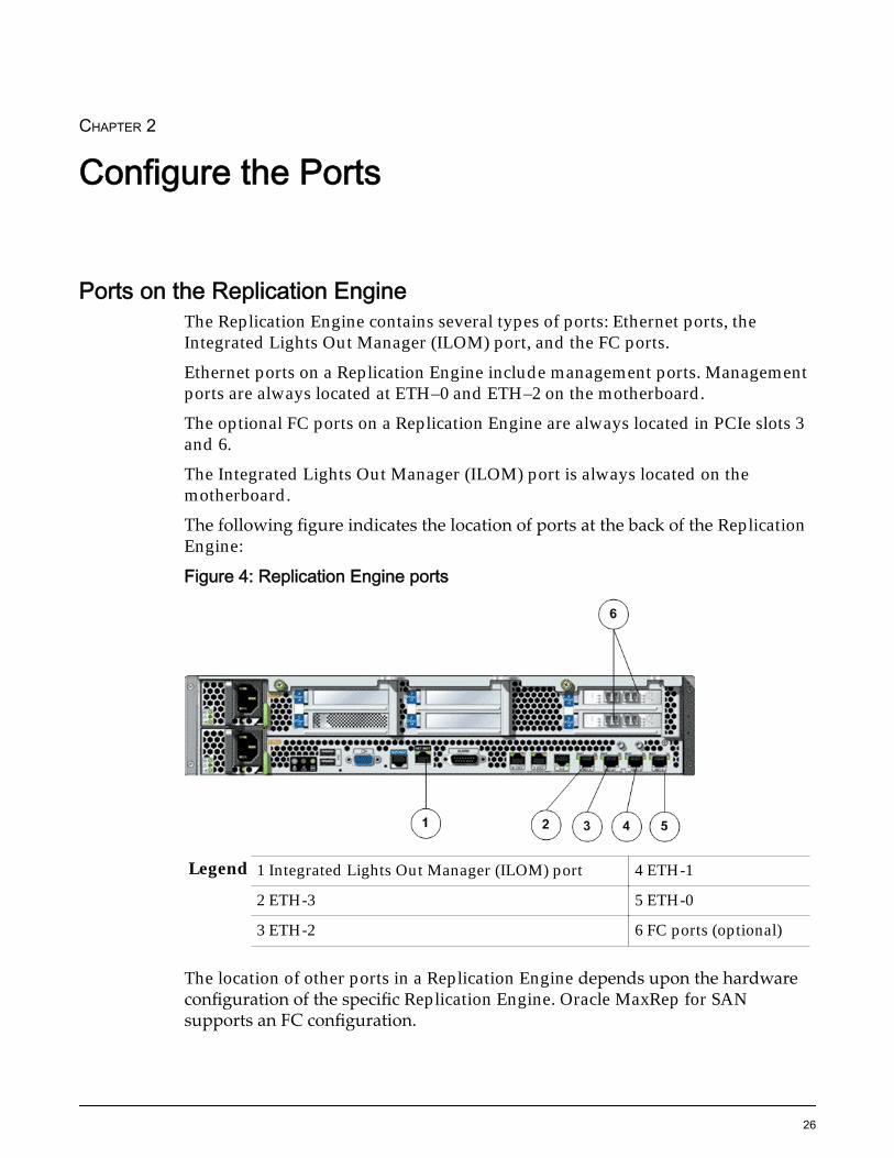
CHAPTER 2
Configure the Ports
Ports on the Replication EngineThe Replication Engine contains several types of ports: Ethernet ports, theIntegrated Lights Out Manager (ILOM) port, and the FC ports.
Ethernet ports on a Replication Engine include management ports. Managementports are always located at ETH–0 and ETH–2 on the motherboard.
The optional FC ports on a Replication Engine are always located in PCIe slots 3and 6.
The Integrated Lights Out Manager (ILOM) port is always located on themotherboard.
The following figure indicates the location of ports at the back of the ReplicationEngine:
Figure 4: Replication Engine ports
Legend 1 Integrated Lights Out Manager (ILOM) port 4 ETH-1
2 ETH-3 5 ETH-0
3 ETH-2 6 FC ports (optional)
The location of other ports in a Replication Engine depends upon the hardwareconfiguration of the specific Replication Engine. Oracle MaxRep for SANsupports an FC configuration.
26

Related LinksILOM PortFibre Channel PortsEthernet Ports
HBA Slot and Port Usage for Supported ConfigurationsBased on the replication configuration, HBAs are installed in the PCIe slots of theReplication Engine.
The following table shows the number of HBAs that must be installed for thevarious configurations:
Table 3: Number of HBAs required based on configuration type
Configuration Number of HBAs
Dual port 8 Gb/sFC
Dual port 10 Gb/sRJ45
Dual port10 Gb/sSFP
iSCSI configuration using RJ45connectors
0 2 0
iSCSI configuration using SFP oroptical connectors
0 0 3
FC configuration 2 0 0
FC and iSCSI configuration usingRJ45 connectors
2 2 0
FC and iSCSI configuration usingoptical or SFP connectors
2 0 3
Note: A Replication Engine can have two dual port 10 Gb/s RJ45 HBA or threedual port 10 Gb/s SFP HBA.
Related LinksiSCSI Configuration Using RJ45 ConnectorsFC Configuration Using RJ45 ConnectorsFC ConfigurationiSCSI Configuration Using SFP or Optical ConnectorsFC Configuration Using SFP or Optical Connectors
FC ConfigurationThe FC configuration is the most common implementation of the Oracle MaxRepfor SAN. The FC configuration provides an FC data path between the Oracle FS
Configure the Ports
27

System and the Oracle MaxRep Replication Engine. The Replication Engine isconnected to the customer’s SAN network using 8 Gb/s FC connections.
The FC configuration requires two 8 Gb/s FC HBA to be installed in the PCI slotsof the Replication Engine, in addition to the standard SAS RAID controller. Thefollowing figure indicates the HBAs that must be installed on the ReplicationEngine PCI slots for the FC configuration.
Figure 5: HBA ports for FC configuration
Legend 1 Slot 1: SAS RAID controller HBA 4 Slot 4: Empty
2 Slot 2: Empty 5 Slot 5: Empty
3 Slot 3: 8 Gb/s FC HBA 6 Slot 6: 8 Gb/s FC HBA
FC Configuration Using RJ45 ConnectorsFC configuration using RJ45 connectors is used for implementations, where theOracle FS System has FC SAN network connectivity. The FC configurationprovides an FC SAN data path between the Oracle FS System and the OracleMaxRep Replication Engine. The FC SAN data path is the primary data path fordata transfers between the Oracle FS System and the Replication Engine. TheOracle MaxRep Replication Engine is connected to the customer’s LAN using 1Gb/s or 10 Gb/s RJ45 connections.
The FC configuration using RJ45 connectors requires two 8 Gb/s FC HBAs andtwo 10 Gb/s RJ45 HBAs to be installed in the PCI slots of the Replication Engine,other than the standard SAS RAID controller. The following figure indicates theHBAs that must be installed on the Replication Engine PCI slots for the FCconfiguration using RJ45 connectors.
Configure the Ports
28
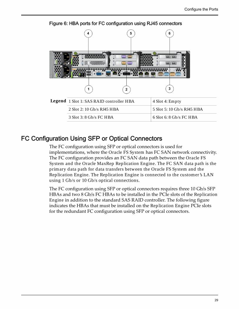
Figure 6: HBA ports for FC configuration using RJ45 connectors
Legend 1 Slot 1: SAS RAID controller HBA 4 Slot 4: Empty
2 Slot 2: 10 Gb/s RJ45 HBA 5 Slot 5: 10 Gb/s RJ45 HBA
3 Slot 3: 8 Gb/s FC HBA 6 Slot 6: 8 Gb/s FC HBA
FC Configuration Using SFP or Optical ConnectorsThe FC configuration using SFP or optical connectors is used forimplementations, where the Oracle FS System has FC SAN network connectivity.The FC configuration provides an FC SAN data path between the Oracle FSSystem and the Oracle MaxRep Replication Engine. The FC SAN data path is theprimary data path for data transfers between the Oracle FS System and theReplication Engine. The Replication Engine is connected to the customer’s LANusing 1 Gb/s or 10 Gb/s optical connections.
The FC configuration using SFP or optical connectors requires three 10 Gb/s SFPHBAs and two 8 Gb/s FC HBAs to be installed in the PCIe slots of the ReplicationEngine in addition to the standard SAS RAID controller. The following figureindicates the HBAs that must be installed on the Replication Engine PCIe slotsfor the redundant FC configuration using SFP or optical connectors.
Configure the Ports
29

Figure 7: HBA ports for FC configuration using SFP or optical connectors
Legend 1 Slot 1: SAS RAID controller HBA 4 Slot 4: 10 Gb/s SFP HBA
2 Slot 2: 10 Gb/s SFP HBA 5 Slot 5: 10 Gb/s SFP HBA
3 Slot 3: 8 Gb/s FC HBA 6 Slot 6: 8 Gb/s FC HBA
Ethernet PortsBased on the configuration, there are four to 10 Ethernet ports on the ReplicationEngine.
The Ethernet ports on the Replication Engine are used for the followingmaintenance and management purposes:
• Administrator access to the Oracle MaxRep graphical user interface (GUI)
• Software installation and upgrades
• Management communication with other Replication Engines
• In an asynchronous replication, the transfer of replicated data andmetadata between the source Replication Engine and the target ReplicationEngine
• Communication between Replication Engines and Oracle FS Systems
• Communication between Replication Engines and application servers
Fibre Channel PortsThe FC ports on the HBA of the Oracle MaxRep Replication Engine are used toaccess the primary and secondary LUNs on the Oracle FS Systems over the SANfabric.
During synchronous replication, the FC ports allow access to both the source andtarget LUNs. During asynchronous replication, the FC ports on the Oracle FSSystem Replication Engine at the primary site allow access to the primary siteLUNs and the FC ports on the Replication Engine at the secondary site allowaccess to the secondary site LUNs.
Configure the Ports
30

There are three types of FC ports on a Replication Engine:
ApplianceInitiator Source(AIS) ports orinitiator portsfor source LUNs:
Used for read-only access to the source LUN during theinitial synchronization. The initiator port for source LUNsmust be zoned to the Controller ports on the source andtarget Oracle FS Systems. AIS ports are virtual ports that arelocated on port 1 of each FC HBA on the Replication Engine.
ApplianceInitiator Target(AIT) Ports orinitiator portsfor target LUNs:
Used for read and write access to the target LUN during theinitial synchronization. The AIT ports are used for access toany LUNs that are mounted for use on the ReplicationEngine. The AIT ports are also used to write data to thesource Oracle FS System during data recovery.The AIT ports are used for /home, /Retention, /Web, and /backup LUN mapping. The initiator for the target LUNmapping port must be zoned to the Controller ports on thesource and target Oracle FS Systems. AIT ports are virtualports that are located on port 1 of each FC HBA on theReplication Engine.
Appliance Target(AT) ports ortarget ports forthe write splitterand the writemirror:
Used to accept IOs from the source Oracle FS System. Theport on the Oracle FS System Controller behaves like aninitiator port when it is used for replication. The AT ports arealso used by hosts that access virtual snapshots on theReplication Engine.Target ports must be zoned to the source and target Oracle FSSystem Controller ports and to any hosts accessing virtualsnapshots from the Replication Engine. AT ports are physicalports that are located on port 2 of each FC HBA on theReplication Engine.
Tip: Connect all the FC ports from each HBA to one SAN fabric. Connect HBAsto separate fabrics to minimize points of failure and to ensure redundancy.
ILOM PortThe Integrated Lights Out Manager (ILOM) port, a 100 Base-T Ethernet port, isused by Oracle Customer Support for remote management over TCP/IP to allowconsole access to the Replication Engine. The ILOM port also allows access toseveral management features like Call-Home, event logs, and system healthinformation. The ILOM port is used for remote recovery after a componentreplacement within the Replication Engine or after other system recoveryoperations and for maintenance and software installation and upgrades.
Configure the Ports
31

Figure 8: ILOM port on the Replication Engine
Legend 1 ILOM port
The ILOM port on the Replication Engine is connected to the customermanagement network and must be in the same subnet as the Oracle FS System.
Related LinksLog in to the Replication Engine Using the ILOM PortSet the IP Address of the WorkstationConfigure ILOM NetworkDefault Network Port Settings
Default Network Port SettingsThe following table lists the default Ethernet and ILOM port settings:
Table 4: Default network port settingsNetworkport
Settings Default value
ETH-0 IP 10.0.0.11
Subnet mask 255.255.255.0
Default gateway 10.0.0.1
User ID root
Password inScott!
ILOM IP 10.0.0.12
Subnet mask 255.255.255.0
Default gateway 10.0.0.1
User ID root
Password changeme
Configure the Ports
32

Table 4: Default network port settings (continued)Networkport
Settings Default value
MaxRepuserinterface(UI) accesscredentials
User ID admin
Password password
Note: Ensure that the ILOM port configuration information is available beforecontacting Oracle Customer Support for assistance. To adhere to Oracle securitybest practices, the default ILOM password should be changed prior to connectingthe ILOM port to the management network.
Related LinksConfigure ILOM NetworkChange Default ILOM Password
Configure the Ports
33

CHAPTER 3
Install the Replication Engine
Engine Component Unpacking and InspectionThe Oracle MaxRep Replication Engine is shipped in a single box, whichincludes a rail kit, two 9.84 feet (3 meter) power cords, a cable management arm(CMA), and other accessories in a pink polythene bag.
Caution: A Replication Engine weighs approximately 41 lbs. (18.59 kg). Usecaution when lifting or installing it.
Caution: Before you handle a component, make sure that you have takenelectrostatic discharge (ESD) precautions:
• The minimum requirement is an anti-static wrist strap connected to a hardground. Remove components from their packaging and place them on anESD-qualified table that is equipped with ground points for wrist straps.
• Static charges can build up rapidly on rolling carts. If you transport ahardware component by cart, ground the cart with a drag chain on an ESDfloor. If there is no ESD cart available or ESD floor, ground yourself beforeyou touch a component that has been transported on a cart.
Required ToolsBefore starting the installation or servicing of a Replication Engine, be sure youhave the required equipment and tools available.
Table 5: Required toolsTool Purpose IllustrationPhillips-head Number 1screwdriver and a Phillips-head Number 2 screwdriver
Remove and secureReplication Engine hardwarecomponents.
Offset box wrench, 13/32inches (10 millimeters)
Work with adjustablemounting rail assemblies.
Torx® T20 screwdriver Attach rail assemblies andsecure hardwarecomponents to the rails.
Wire cutters Cut cable wraps on thepower cords.
34

Replication Engine Placement in the RackSeveral options are available for placing the Oracle MaxRep Replication Enginein the rack based on the number of Replication Engines that must be installed.
For rack-ready systems that include Oracle MaxRep Replication Engines, thefollowing order for installing the components in the rack to match the factoryconfiguration as closely as possible:
• First, install the Drive Enclosures starting from the bottom of the rack. Theamount of RU space used by the Drive Enclosures varies by the number ofReplication Engines that must be installed.
If only one Replication Engine must be installed in the rack, install theDrive Enclosures until the 16 RU slot is reached.
• After the 16 RU slot is reached, if the next Drive Enclosure to beinstalled is a 2U DE2-24P Drive Enclosure, install the DE2-24P DriveEnclosure into the rack at 17 RU and 18 RU. Then, install theReplication Engine at 19 RU and 20 RU.
• After the 16 RU slot is reached, if the next Drive Enclosure to beinstalled is a 4U DE2-24C Drive Enclosure, install the ReplicationEngine at 17 RU and 18 RU.
If two Replication Engines must be installed, install the Drive Enclosuresuntil the 14 RU slot is reached.
• After the 14 RU slot is reached, if the next Drive Enclosure to beinstalled is a 2U DE2-24P Drive Enclosure, install the DE2-24P DriveEnclosure into the rack at 15 RU and 16 RU. Then, install the firstReplication Engine at 17 RU and 18 RU and install the secondReplication Engine at 19 RU and 20 RU.
• After the 14 RU slot is reached, if the next Drive Enclosure to beinstalled is a 4U DE2-24C Drive Enclosure, install the firstReplication Engine at 15 RU and 16 RU. Then, install the secondReplication Engine at 17 RU and 18 RU.
If three Replication Engines must be installed, install the Drive Enclosuresuntil the 12 RU slot is reached.
• After the 12 RU slot is reached, if the next Drive Enclosure to beinstalled is a 2U DE2-24P Drive Enclosure, install the DE2-24P DriveEnclosure into the rack at 13 RU and 14 RU. Then, install the firstReplication Engine at 15 RU and 16 RU. Install the secondReplication Engine at 17 RU and 18 RU. Install the third ReplicationEngine at 19 RU and 20 RU.
• After the 12 RU slot is reached, if the next Drive Enclosure to beinstalled is a 4U DE2-24C Drive Enclosure, install the firstReplication Engine at 13 RU and 14 RU. Install the second
Install the Replication Engine
35
Replication Engine at 15 RU and 16 RU. Install the third ReplicationEngine at 17 RU and 18 RU.
If four Replication Engines must be installed, install the Drive Enclosuresuntil the 10 RU slot is reached.
• After the 10 RU slot is reached, if the next Drive Enclosure to beinstalled is a 2U DE2-24P Drive Enclosure, install the DE2-24P DriveEnclosure into the rack at 11 RU and 12 RU. Then, install the firstReplication Engine at 13 RU and 14 RU. Install the secondReplication Engine at 15 RU and 16 RU. Install the third ReplicationEngine at 17 RU and 18 RU. Install the fourth Replication Engine at19 RU and 20 RU.
• After the 10 RU slot is reached, if the next Drive Enclosure to beinstalled is a 4U DE2-24C, install the first Replication Engine at 11RU and 12 RU. Install the second Replication Engine at 13 RU and 14RU. Install the third Replication Engine at 15 RU and 16 RU. Installthe fourth Replication Engine at 17 RU and 18 RU.
• Then, install the Pilots above the Replication Engines.
• Then, install the Controllers immediately above the Pilots.
• Then, install the remaining Drive Enclosures above the Controllers.
• Finally, install filler panels in all available RU spaces in the rack.
Contact Oracle Customer Support before power cycling a Oracle FS Systemsystem except in the event of an emergency. In an emergency, shut off all powerand then contact Oracle Customer Support.
Replication Engine Pre-Installation ChecklistVarious checks and actions need to be performed to install the Oracle MaxRepfor SAN Replication Engine.
Note: Print this pre-installation checklist and check off each task after youcomplete it.
Table 6: Pre-installation checklistPre-installation tasks
❑ Verify that you have all the components for assembly in the ReplicationEngine rail kit by matching the components with the parts list inside thepackage.
❑ Verify that you have all the required tools available for installation. Referto the required tools listed in this guide.
❑ Verify that the anti-static wrist strap and the electro-static discharge (ESD)cart are available.
❑ Ensure that you have assistance in lifting the Replication Engine.
Install the Replication Engine
36

Table 6: Pre-installation checklist (continued)Pre-installation tasks
❑ Check that you have two power cables with IEC 320 C13 connectors.Verify that the source of the power supplies has the available capacity tocarry the maximum load for the circuit.
❑ Verify that the circuit contains 120, 208, or 230 V power distribution units(PDUs).
❑ Check that you have two Fibre Channel (FC) connections to each of twostorage area network (SAN) fabric switches.
❑ Check that you have access to the SAN fabric switches so that you cangather World Wide Port Name (WWPN) information and perform aliasingand zoning.
Note: An alias is a descriptive name for a WWPN or port number, whichmakes the zone configuration much easier to read. Zoning is used as amethod of access control for a SAN fabric to keep ports fromcommunicating with one another. Refer to your SAN switchmanufacturer's administrator guide for additional information on aliasesand zoning.
❑ Check that you have two to nine Ethernet connections to the local areanetwork (LAN) switches. Consult the wiring diagrams to determine thenumber of Ethernet connections required for your specific ReplicationEngine configuration.
❑ Check that you have the Replication Engine hostname.
❑ Check that you have the IP address, netmask, and the default gatewayaddress for the Ethernet (ETH-0) port.
❑ Check that you have the IP address, netmask, and the default gatewayaddress for the Integrated Lights Out Manager (ILOM) port.
❑ Check that you have the IP address of the domain name server (DNS) andthe DNS domain name.
❑ Check that you have the IP address of the Network Time Protocol (NTP)server.
❑ If more than one Replication Engine must be installed for a highavailability (HA) configuration, check that you have the IP address for theactive and passive Replication Engine as well as an additional IP addressfor the high availability (HA) cluster. Additionally, you will also require aping node and a multicast IP address for HA .
❑ Ensure that you have a copy of the Oracle MaxRep Replication Enginesoftware for upload during installation.
❑ If the Replication Engine will be installed in a non-Oracle rack, verify thatthe non-Oracle rack will be compatible with the Replication Engine.
❑ Verify that the shipment for the Replication Engine has arrived at the site.
❑ Allow the system to acclimatize (power off) at the customer site.
Install the Replication Engine
37

Replication Engine Installation ChecklistInstallation of an Oracle MaxRep Replication Engine is performed by OracleCustomer Support. Certain verifications and actions will be required for eachReplication Engine during installation.
Note: Print this installation checklist and check off each task after you completeit.
Table 7: Installation checklistInstallation tasks
❑ Unpack the shipment and inspect all components.
❑ Unpack the Replication Engine outside the data center to ensure that nocontamination or dust is released.
❑ Verify that all packing material has been removed and nothing is blockingthe fans and air vents.
❑ Gather all the excess spare parts like cables and documentation together.
❑ Always load equipment into a rack from the bottom upwards so that itwill not become top-heavy and tip over. Deploy the rack's anti-tilt bar toprevent the rack from tipping during equipment installation.
❑ Install the rack rails and the Replication Engine in the rack.
❑ Launch a remote session to the Integrated Lights Out Manager (ILOM)port. Configure the Integrated Lights Out Manager (ILOM) port passwordusing a laptop prior to connecting the Replication Engine to the customernetwork using the steps outlined in the ILOM Security Guide..
❑ Label all the cables clearly and use cable binders.
❑ Connect all Fibre Channel (FC) and Ethernet cables as described in thisguide.
❑ Configure the operating system on the Oracle MaxRep Replication Engine.
It is important that the Replication Engine has the correct IP addressesupon installation.
❑ Install the correct software version and apply all the required patches andor hotfixes for Oracle MaxRep for SAN.
❑ Verify browser access to the Oracle MaxRep for SAN graphical userinterface (GUI) and the command line interface (CLI) for the ReplicationEngine.
Install the Replication Engine
38

Installing the Replication Engine RailsAdding Oracle MaxRep Replication Engines in the rack requires you to installrack rails in the rack and slide rails on the chassis for each Replication Enginethat you plan to add.
Replication Engine rail kits can be installed in the Sun Rack 900, the Sun Rack1000, and third-party ANSI/EIA 310-D-1992 or IEC 60927 compliant racks withthe following types of holes:
• Square
• Round
• Threaded
Figure 9: Examples of supported rack holes
Legend 1 Square holes 2 Round holes
3 Threaded holes
Related LinksInstall the Rack Rails for the Replication EngineInstall the Replication Engine CMAInsert the Replication Engine Into a RackReplication Engine Rail Kit Parts
Replication Engine Rail KitsThe Replication Engine rail kit contains the following items:
• One slide rail that attaches to the rack posts
• One mounting bracket that attaches to the Replication Engine chassis
• CMA with six pre-installed cable clips
• Package of mounting screws and nuts in assorted sizes to fit various typesof racks and cabinets
• Manufacturer's instruction sheet for the CMA
The following table summarizes the mounting hardware packaged with theReplication Engine rail kits.
Install the Replication Engine
39

Table 8: Replication Engine rail kit mounting screwsPacket Contents Quantity Usage
10-32 pan head screw 8 Assemble main and extendersections of left and right rails(Typically, left and right rails areshipped pre-assembled)
8-32 pan head screw 4 Mount left and right rails to frontof cabinet rails
Metric M6 pan head screw 8 • Mount left and rightrails to back of cabinetrails
• Secure front of chassis toleft and right cabinetrails
6–32 flat head screw 2 Secure back of chassis to left andright side rails
Tip: Ensure that you have all of the parts in the Replication Engine rail kit beforeyou begin the installation of the Replication Engine rails on the rack and theReplication Engine chassis.Note: To locate part numbers for the rail kits, open Oracle System Handbook(https://support.oracle.com/handbook_private/index.html) and go to theOracle FS1 Flash Storage System components list. Part numbers are listed in thecomponents list.
Install the Rack Rails for the Replication EnginePrior to adding Replication Engines, install rails into the rack for each ReplicationEngine that you plan to add.
Prerequisites: • Ensure that you have adequate room to work around therack while installing the rails and the Replication Engine.
• Attach an electrostatic discharge (ESD) wrist strap to yourwrist, and stand on an ESD mat while replacingcomponents.
• Ensure that you have a Phillips Number 2 screwdriverwith at least a 4-inch shaft.
• If you are installing the rails in a rack with threaded holes,make sure you have a Torx Number 20 screwdriver.
1 Mark the rack mount hole where you plan to mount the ReplicationEngine.
Install the Replication Engine
40
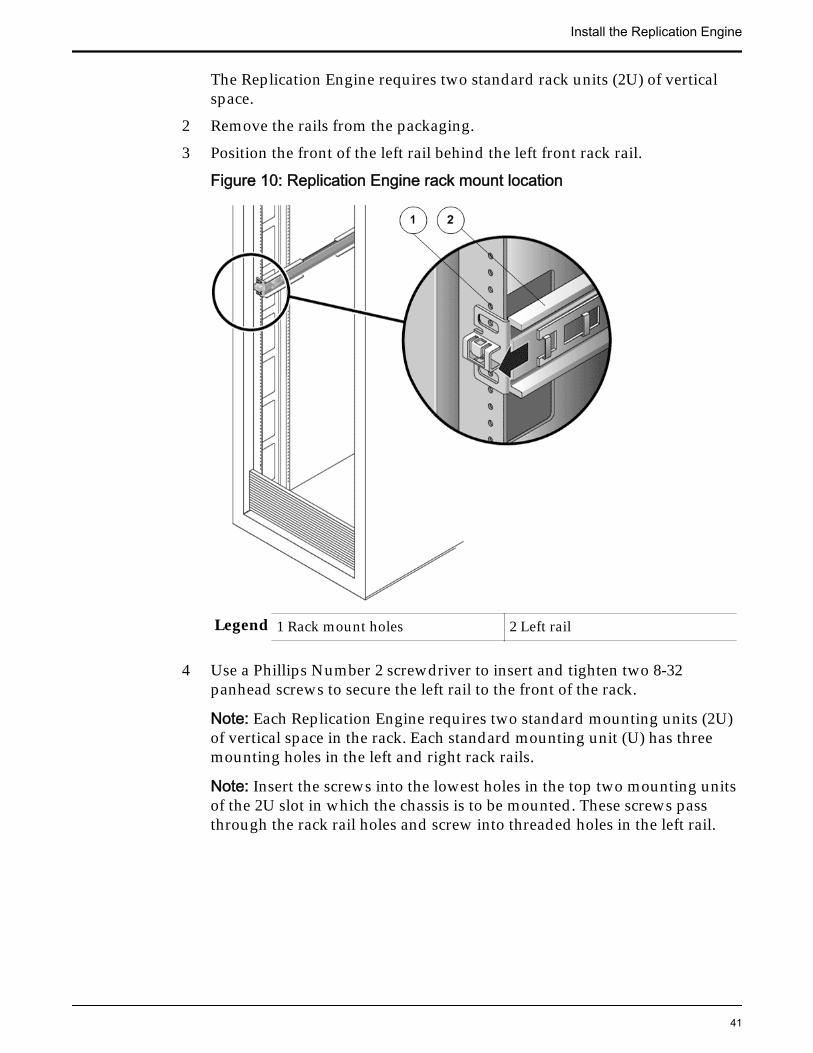
The Replication Engine requires two standard rack units (2U) of verticalspace.
2 Remove the rails from the packaging.
3 Position the front of the left rail behind the left front rack rail.
Figure 10: Replication Engine rack mount location
Legend 1 Rack mount holes 2 Left rail
4 Use a Phillips Number 2 screwdriver to insert and tighten two 8-32panhead screws to secure the left rail to the front of the rack.
Note: Each Replication Engine requires two standard mounting units (2U)of vertical space in the rack. Each standard mounting unit (U) has threemounting holes in the left and right rack rails.
Note: Insert the screws into the lowest holes in the top two mounting unitsof the 2U slot in which the chassis is to be mounted. These screws passthrough the rack rail holes and screw into threaded holes in the left rail.
Install the Replication Engine
41

Figure 11: Left rail secured to the front of the rack
Legend 1 Rack 2 8–32 screws to secure left rail torack
3 Left rail
5 Repeat the above two steps for the right rail.
6 At the back of the rack, adjust the length of the left rail as needed to fit therack, and position the rail flange over the face of the rack rail.
Install the Replication Engine
42

Figure 12: Left rail adjusted at the back of the rack
Legend 1 Back of the rack 2 Left rail
7 Align the rail flange so that the mounting holes correspond to those at thefront of the rack.
8 Use a Phillips screwdriver to insert and tighten four metric M6 screws (twoon each side) at the back of the rail.
9 Repeat the above three steps for the right rail.
10 Using a Phillips Number 2 screwdriver, tighten the eight 10-32 panheadadjustment screws (four on each side) toward the back of each rail.
Install the Slide Rails for the Replication Engine1 Extend the mounting brackets completely out of their respective slide rails.
Tip: To extend the mounting brackets out of the slide rails, simultaneouslypress and hold the upper and lower lock buttons of the slide rail lock.Then, pull the mounting bracket out until it locks in the extended position.
Install the Replication Engine
43

Figure 13: Slide rail assembly unlocked
Legend 1 Slide rail assembly 2 Slide rail lock button
2 Slide the mounting bracket release button, and then slide the mountingbracket out of the slide rail.
Figure 14: Mounting bracket release button
Legend 1 Slide rail 2 Mounting bracket releasebutton
3 Mounting bracket
Install the Replication Engine
44

Figure 15: Slide rail middle section unlocked
Legend 1 Slide rail 2 Metal lever
Tip: Press the metal lever on the middle section of the slide rail to unlockthe slide rail, and then push the middle section back into the rack.
3 Attach a mounting bracket to the right side of the Replication Enginechassis.
Figure 16: Mounting bracket attached to the chassis
Legend 1 Mounting bracket 2 Replication Engine chassis
Install the Replication Engine
45

Tip: Position the mounting bracket against the Replication Engine chassisso that the slide rail lock is at the front and the three keyed openings on themounting bracket are aligned with the three locating pins on the side of thechassis. With the heads of the three locating pins protruding though thethree keyed openings in the mounting bracket, pull the mounting brackettoward the front of the chassis until the bracket locks into place with anaudible click.
4 Attach the second mounting bracket to the left side of the ReplicationEngine chassis.
5 Determine which rack hole numbers to use when attaching the slide railsto the rack posts.
Note: The Replication Engine is two rack units tall (2U). The slide rails willoccupy the lower half of the 2U space.
6 Determine which screws you will use to mount the slide rails.
Tip: If your rack has threaded mounting holes in the rack posts, determinewhether the threads are metric or standard. Select the appropriate screwsfrom the package included in the mounting kit. If your rack does not havethreaded mounting holes, the mounting screws are secured with a cagednut.
7 Attach a slide rail to the right front rack post.
Figure 17: Slide rail mounted on the rack post
Legend 1 Rack post 2 Slide rail
Tip: Loosely attach the front of a slide rail to the right front rack post usingtwo screws but do not tighten the screws yet. Adjust the length of the sliderail by sliding the back mounting flange to reach the outside edge of the
Install the Replication Engine
46
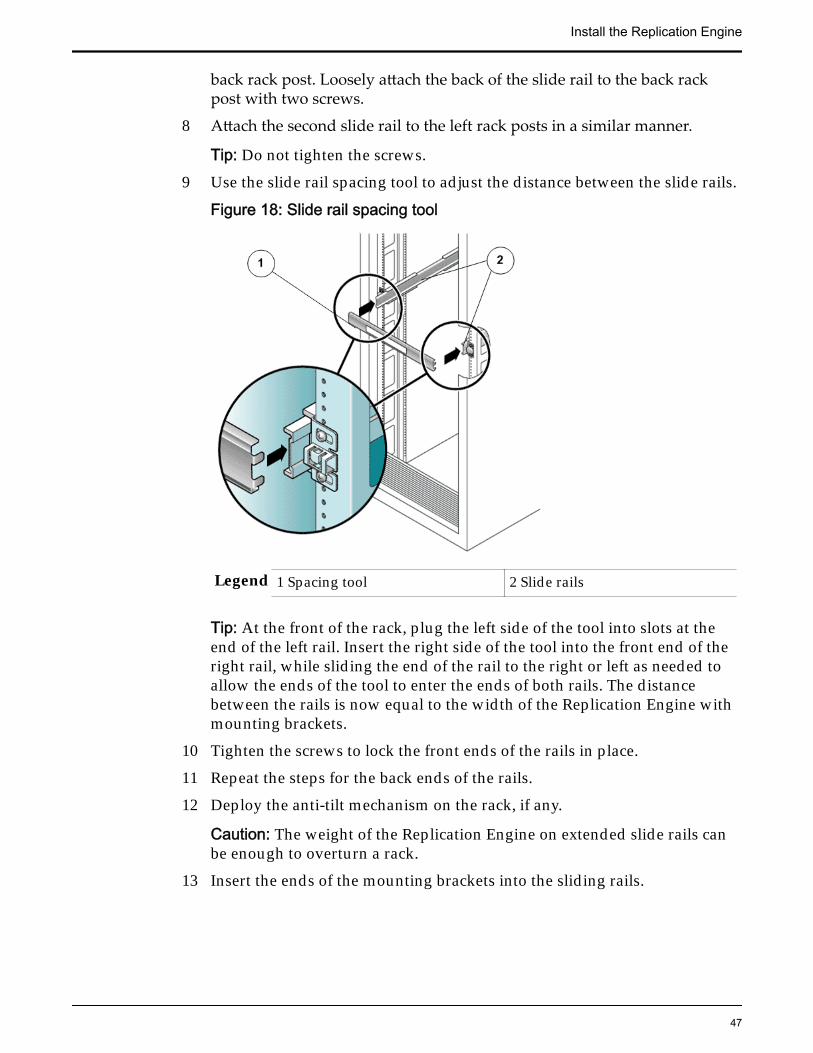
back rack post. Loosely attach the back of the slide rail to the back rackpost with two screws.
8 Attach the second slide rail to the left rack posts in a similar manner.
Tip: Do not tighten the screws.
9 Use the slide rail spacing tool to adjust the distance between the slide rails.
Figure 18: Slide rail spacing tool
Legend 1 Spacing tool 2 Slide rails
Tip: At the front of the rack, plug the left side of the tool into slots at theend of the left rail. Insert the right side of the tool into the front end of theright rail, while sliding the end of the rail to the right or left as needed toallow the ends of the tool to enter the ends of both rails. The distancebetween the rails is now equal to the width of the Replication Engine withmounting brackets.
10 Tighten the screws to lock the front ends of the rails in place.
11 Repeat the steps for the back ends of the rails.
12 Deploy the anti-tilt mechanism on the rack, if any.
Caution: The weight of the Replication Engine on extended slide rails canbe enough to overturn a rack.
13 Insert the ends of the mounting brackets into the sliding rails.
Install the Replication Engine
47
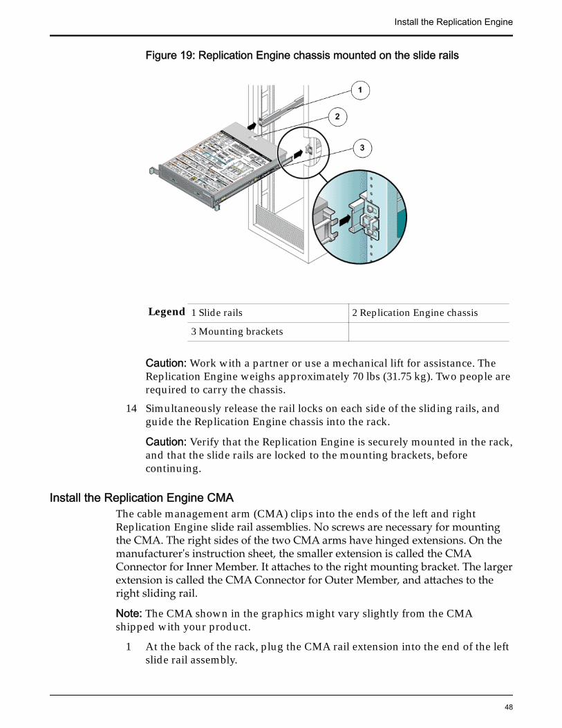
Figure 19: Replication Engine chassis mounted on the slide rails
Legend 1 Slide rails 2 Replication Engine chassis
3 Mounting brackets
Caution: Work with a partner or use a mechanical lift for assistance. TheReplication Engine weighs approximately 70 lbs (31.75 kg). Two people arerequired to carry the chassis.
14 Simultaneously release the rail locks on each side of the sliding rails, andguide the Replication Engine chassis into the rack.
Caution: Verify that the Replication Engine is securely mounted in the rack,and that the slide rails are locked to the mounting brackets, beforecontinuing.
Install the Replication Engine CMAThe cable management arm (CMA) clips into the ends of the left and rightReplication Engine slide rail assemblies. No screws are necessary for mountingthe CMA. The right sides of the two CMA arms have hinged extensions. On themanufacturer's instruction sheet, the smaller extension is called the CMAConnector for Inner Member. It attaches to the right mounting bracket. The largerextension is called the CMA Connector for Outer Member, and attaches to theright sliding rail.
Note: The CMA shown in the graphics might vary slightly from the CMAshipped with your product.
1 At the back of the rack, plug the CMA rail extension into the end of the leftslide rail assembly.
Install the Replication Engine
48

Figure 20: CMA rail extension inserted into the back of the left slide rail
Legend 1 CMA rail extension 2 Slide rail
Caution: Support the CMA during this installation. Do not allow theassembly to hang by its own weight until it is secured by all threeattachment points.
2 Insert the smaller extension into the clip located at the end of the mountingbracket.
Install the Replication Engine
49

Figure 21: Inner CMA connector mounted
Legend 1 Slide rail 2 Inner CMA connector
3 Clip
3 Insert the outer CMA connector into the end of the right sliding rail.
Figure 22: Outer CMA connector attached
Legend 1 Outer CMA connector 2 Slide rail
4 Fully insert the hinged plastic connector at the left side of the CMA into theCMA rail extension.
Install the Replication Engine
50

Figure 23: Left side of the slide rail mounted
Legend 1 Plastic tab on CMA rail extension 2 Slide rail
Verify Operation of the Slide Rails and the CMAPrerequisites: • Before handling a component, touch a grounded surface to
discharge any static electricity.• Attach an electrostatic discharge (ESD) wrist strap to your
wrist, and stand on an ESD mat while replacingcomponents.
• Two people are needed to verify the operation of the sliderails and the cable management arm (CMA): one to movethe Replication Engine in and out of the rack and one toobserve the cables and CMA.
• To reduce the risk of personal injury, stabilize theexpansion rack cabinet and extend all anti-tilt devicesbefore extending the Replication Engine from the rack.
Caution: Work with a partner or use a mechanical lift for assistance. TheReplication Engine weighs approximately 70 lbs (31.75 kg). Two people arerequired to unmount and carry the chassis.
1 Unlock the slide lock buttons at the right and left sides of the ReplicationEngine chassis, and slowly pull the Replication Engine out of the rack untilthe slide rails reach their stops.
Install the Replication Engine
51

Figure 24: Replication Engine slide rails unlocked
Legend 1 Slide rail assembly
2 Slide rail lock button
2 Inspect the attached cables for any binding or kinks.
3 Verify that the CMA extends fully and does not bind in the slide rails.
4 When the Replication Engine is fully extended out, release the mountingbracket release button.
Figure 25: Mounting bracket release button
Install the Replication Engine
52

Legend 1 Slide rail
2 Mounting bracket release button
3 Mounting bracket
5 Slide the Replication Engine back into the rack.
6 Simultaneously unlock both slide rail release buttons, and push theReplication Engine completely into the rack.
Figure 26: Slide rail release button
Legend 1 Slide rail release button
2 Slide rail
Note: The Replication Engine should stop after approximately 15 inches(40 cm) of travel.
7 Verify that the cables and the CMA retracted without binding.
8 Adjust the cable hangers and CMA as required.
Insert the Replication Engine Into a RackPrerequisites: • Ensure that you have a magnetic-tipped Phillips Number 2
screwdriver with at least a four-inch shank.
Install the Replication Engine
53

• Before handling a component, touch a grounded surface todischarge any static electricity.
• Attach an electrostatic discharge (ESD) wrist strap to yourwrist, and ensure that you have an ESD mat. Stand on theESD mat while replacing components.
Caution: Do not power on the Replication Engine until after you have connectedthe Replication Engine to the network.
Caution: Work with a partner or use a mechanical lift for assistance. TheReplication Engine weighs approximately 70 lbs (31.75 kg). Two people arerequired to unmount and carry the chassis.
Caution: Deploy any rack anti-tilt mechanisms before installing the ReplicationEngine into the rack to prevent the rack from tipping over during componentinstallation.
Caution: Always load equipment into a rack from the bottom up so that the rackwill not become top-heavy and tip over.
Caution: Slide-rail-mounted components are not to be used as a shelf or aworkspace.
Caution: Elevated operating ambient temperature: If the Replication Engine isinstalled in a closed or multi-unit rack assembly, the operating ambienttemperature of the rack environment might be greater than room ambienttemperature. Therefore, consideration should be given to installing thecomponents in an environment compatible with the maximum ambienttemperature (TMA) specified for the Replication Engine.
Caution: Reliable earthing: Maintain reliable earthing of rack-mountedcomponents. Pay particular attention to supply connections other than directconnections to the branch circuit (for example, use of power strips).
Caution: Circuit overloading: Consideration should be given to the connection ofthe component to the supply circuit and the effect that overloading of the circuitsmight have on supply wiring. Appropriate consideration of component powerratings should be used when addressing this concern.
Caution: Reduced airflow: Installation of the components in the rack should besuch that the amount of airflow required for safe operation of the equipment isnot compromised.
Caution: Mechanical loading: Mounting of the components in the rack should besuch that a hazardous condition is not created due to uneven mechanicalloading.
1 Using two people, one at each side of the Replication Engine, carefully liftand position the Replication Engine on the bottom ledge of the left andright rails.
Install the Replication Engine
54

Note: Do not use the power supply handles to lift the chassis. Using thepower supply handles to lift the chassis can damage the power suppliesand disrupt electrical power to the Replication Engine.
2 Carefully slide the Replication Engine into the rack until the front flangesof the Replication Engine touch the vertical face of the rack.
3 Use a Phillips screwdriver to install and tighten the four M6 panheadscrews (two on each side) to secure the chassis to the front of the rack.
4 Install and tighten two 6-32 screws (one on each side) at the back of thechassis, to secure the back of the chassis to the rack.
Related LinksReplication Engine Placement in the RackEngine Component Unpacking and InspectionInstall the Rack Rails for the Replication EngineInstall the Slide Rails for the Replication EngineInstall the Replication Engine CMAReplication Engine Pre-Installation ChecklistReplication Engine Installation Checklist
Install the Replication Engine
55

CHAPTER 4
Cable the Replication Engine
Cabling Overview for the Replication EngineTypical customer configurations include Replication Engines with redundantHBAs connected to the ports on the Oracle FS System Controller throughredundant SAN switches. All ports of one HBA in the Replication Engineconnect to the same SAN switch fabric, while all ports of the redundant HBAconnect to an alternate SAN switch fabric.
The following figure illustrates the cabling connections of the ReplicationEngines in a typical Oracle MaxRep for SAN configuration.
Figure 27: Typical cabling connections of Oracle MaxRep Replication Engines
Legend 1 MaxRep high availability clusterwith two redundant ReplicationEngines
3 SAN fabric switch 2
2 SAN fabric switch 1 4 Oracle FS System Controllers
56

Following cables are required to connect the Replication Engine in the rack.
Table 9: Cables
Type Description Cable length
Fibre Channel (FC)patch cables
Connect the FC ports at the backof the Replication Engine to theSAN Switch or SAN fabric towhich the Oracle FS System isconnected. These cables provideconnectivity to the Oracle FSSystem for replication.
50/125 optical FC have adistance limit of 164.04 feet(50 meters) for 8 Gb/s fabricspeed.
Ethernet cables Connect the Ethernet ports on theReplication Engine tomanagement network switchesfor management and to createNIC bonding for portvirtualization.
1Gb/s Twisted Pair
10 Gb/s Twisted Pair
1 Gb/s Optical
10 Gb/s Optical
The Replication Engine user interface is web-based and can be accessed throughan HTTP server running on port 80. The following table summarizes the firewallrules that must be configured:
Table 10: Firewall configuration
Purpose Replication Engine Primary LUN Secondary LUN
User Interface Inbound HTTP
Default: TCP Port80
N/A N/A N/A
Configuration Inbound HTTP
ConfigurationManagement:Port 3306
N/A N/A N/A
Default: TCP Port80
N/A N/A N/A
Or TCP (21 + con-figured passiveport range)
N/A N/A N/A
Or TCP (20 + 21) Outbound FTP or(>1024)
Outbound FTP or(>1024)
N/A
Data resync Inbound TCP Port 873 N/A N/A
FX data (Push ) N/A N/A N/A
FX data (Pull) N/A N/A N/A
Cable the Replication Engine
57
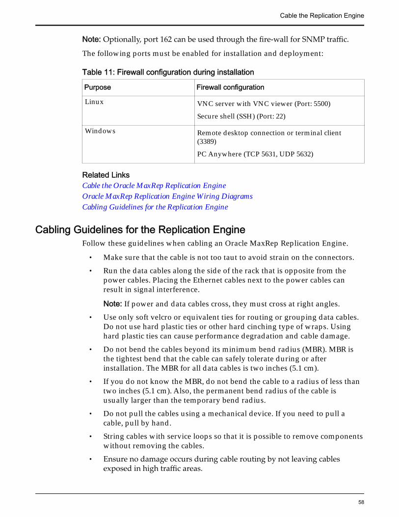
Note: Optionally, port 162 can be used through the fire-wall for SNMP traffic.
The following ports must be enabled for installation and deployment:
Table 11: Firewall configuration during installation
Purpose Firewall configuration
Linux VNC server with VNC viewer (Port: 5500)
Secure shell (SSH) (Port: 22)
Windows Remote desktop connection or terminal client(3389)
PC Anywhere (TCP 5631, UDP 5632)
Related LinksCable the Oracle MaxRep Replication EngineOracle MaxRep Replication Engine Wiring DiagramsCabling Guidelines for the Replication Engine
Cabling Guidelines for the Replication EngineFollow these guidelines when cabling an Oracle MaxRep Replication Engine.
• Make sure that the cable is not too taut to avoid strain on the connectors.
• Run the data cables along the side of the rack that is opposite from thepower cables. Placing the Ethernet cables next to the power cables canresult in signal interference.
Note: If power and data cables cross, they must cross at right angles.
• Use only soft velcro or equivalent ties for routing or grouping data cables.Do not use hard plastic ties or other hard cinching type of wraps. Usinghard plastic ties can cause performance degradation and cable damage.
• Do not bend the cables beyond its minimum bend radius (MBR). MBR isthe tightest bend that the cable can safely tolerate during or afterinstallation. The MBR for all data cables is two inches (5.1 cm).
• If you do not know the MBR, do not bend the cable to a radius of less thantwo inches (5.1 cm). Also, the permanent bend radius of the cable isusually larger than the temporary bend radius.
• Do not pull the cables using a mechanical device. If you need to pull acable, pull by hand.
• String cables with service loops so that it is possible to remove componentswithout removing the cables.
• Ensure no damage occurs during cable routing by not leaving cablesexposed in high traffic areas.
Cable the Replication Engine
58

• Do not set any hardware components or other objects on top of the cables.
• Do not let the cables get pinched by closed doors or door lock hardware.Do not twist the cables.
• Do not wrap the fiber optic cables around your hands, arms, or shoulders,as this may result in causing sharp bends or a small coiling radius. This canalso impart a twist to the cable upon uncoiling.
• Ensure that all cables are labeled correctly.
Note: Ethernet and fibre channel (FC) cables are not shipped with the ReplicationEngines. Cables must be ordered separately.
Note: We recommend 50/125 multi-mode optical cable for data paths. However,we also support a 62.5/125 core diameter for the multi-mode optical cables, if thecable distance limitations are followed.
Cable the Oracle MaxRep Replication EngineConnect the ports as indicated below to cable the Oracle MaxRep ReplicationEngine.
Prerequisites: • Refer to the site preparation plan to identify the OracleMaxRep for SAN configuration to deploy before installingor cabling the Oracle MaxRep Replication Engine.
• Identify the Ethernet ports that are to be used on theReplication Engine.
• Obtain a range of IP addresses for the Replication EngineEthernet ports.
• Ensure that the customer’s network firewalls areconfigured to permit access to the Integrated Lights OutManager (ILOM) interface.
• Refer to the site preparation plan to identify the Oracle MaxRep for SANconfiguration to deploy before installing or cabling the Oracle MaxRepReplication Engine.
• Identify the Ethernet ports that are to be used on the Replication Engine.
• Obtain a range of IP addresses for the Replication Engine Ethernet ports.
• Ensure that the customer’s network firewalls are configured to permitaccess to the Integrated Lights Out Manager (ILOM) interface.
1 Connect the Ethernet ports to the management network switches.
Needed connections:Ethernet port (ETH-0) and (ETH-2) of the Replication Engine must beconnected to the management network switches using Cat5e Ethernetcables.
Cable the Replication Engine
59

Note: ETH-2 is connected for redundant port bonding. If ETH-2 is notconnected, only ETH-0 is used for management communications. In case ofport bonding (FC-only), the Ethernet port (ETH-1) may be connected to themanagement network.
2 Connect the ILOM port to the management network to permit remoteserviceability.
The ILOM port is required for Call‑Home functionality. Not connecting orconfiguring the ILOM port for the management network preventsnotification of hardware failures.
3 Connect all four ports of HBA1 on the Replication Engine to the customer’smain Fibre Channel (FC) fabric.
In a dual fabric environment, connect both FC ports of HBA2 to thealternate FC fabric.
Note: To ensure that the Replication Engine can recover from SAN fabricfailures, two HBAs are required on each Replication Engine.
Related LinksCabling Overview for the Replication EngineCabling Guidelines for the Replication EngineOracle MaxRep Replication Engine Wiring Diagrams
Oracle MaxRep Replication Engine Wiring DiagramsUse the appropriate wiring diagram for your replication configuration to cablethe Oracle MaxRep Replication Engine.
The wiring diagrams below represent the following Oracle MaxRep for SANconfigurations:
• Fibre Channel (FC) configuration
• iSCSI configuration using RJ45 connectors
• FC and iSCSI configuration using RJ45 connectors
• iSCSI configuration using SFP or optical connectors
• FC and iSCSI configuration using SFP or optical connectors
The following figure provides information on the cable connections with FCconfiguration.
Note: The dotted line in the following illustrations separate the Oracle FS Systemhardware from the customer environment.
Cable the Replication Engine
60

Figure 28: FC configuration
Legend 1 SAN fabric switch A 2 Ethernet switch
3 SAN fabric switch B 4 Oracle MaxRep Replication Engine
5 Oracle FS System Controllers andPilots (Drive Enclosures not shown)
Note: For FC configuration, both ports of HBA 1 are connected to the SAN fabricswitch A and both ports of HBA 2 are connected to SAN fabric switch B. Theports ETH-0 and ETH-2 are Gigabit Ethernet (GbE) or 10 Gb/s auto-negotiated.The Integrated Lights Out Manager (ILOM) port is 100 Bit Torrent (BT) auto-negotiated.
The following figure provides information on the cable connections with iSCSIconfiguration using RJ45 connectors.
Cable the Replication Engine
61

Figure 29: iSCSI configuration using RJ45 connectors
Legend 1 Oracle MaxRep ReplicationEngine
2 Oracle FS System Controllers andPilots ( Drive Enclosures not shown)
3 Ethernet switch
Note: For iSCSI configuration using RJ45 connectors, ports ETH-0 through ETH-7are GbE or 10 Gb/s auto-negotiated. The ILOM port is 100 BT auto-negotiated.
The following figure provides information on the cable connections for a FC andiSCSI configuration using RJ45 connectors.
Cable the Replication Engine
62
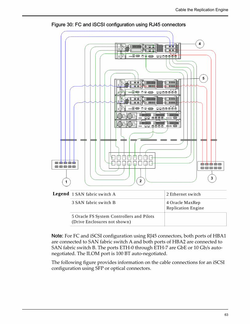
Figure 30: FC and iSCSI configuration using RJ45 connectors
Legend 1 SAN fabric switch A 2 Ethernet switch
3 SAN fabric switch B 4 Oracle MaxRepReplication Engine
5 Oracle FS System Controllers and Pilots(Drive Enclosures not shown)
Note: For FC and iSCSI configuration using RJ45 connectors, both ports of HBA1are connected to SAN fabric switch A and both ports of HBA2 are connected toSAN fabric switch B. The ports ETH-0 through ETH-7 are GbE or 10 Gb/s auto-negotiated. The ILOM port is 100 BT auto-negotiated.
The following figure provides information on the cable connections for an iSCSIconfiguration using SFP or optical connectors.
Cable the Replication Engine
63

Figure 31: iSCSI configuration using SFP or optical connectors
Legend 1 Oracle MaxRep Replication Engine 2 Oracle FS System Controllers andPilots ( Drive Enclosures not shown)
3 Ethernet switch
Note: For iSCSI configuration using SFP or optical connectors, ports ETH-0 andETH-2 are GbE or 10 Gb/s auto-negotiated twisted pair and ports ETH-4 throughETH-9 are GbE or 10 Gb/s auto-negotiated optical. The ILOM port is 100 BT auto-negotiated.
The following figure provides information on the cable connections for an FCand iSCSI configuration using SFP or optical connectors.
Cable the Replication Engine
64

Figure 32: FC and iSCSI configuration using SFP or optical connectors
Legend 1 SAN fabric switch A 2 Ethernet switch
3 SAN fabric switch B 4 Oracle MaxRep Replication Engine
5 Oracle FS System Controllers andPilots ( Drive Enclosures not shown)
Note: For FC and iSCSI configuration using SFP or optical connectors, both portsof HBA1 are connected to SAN fabric switch A and both ports of HBA2 areconnected to SAN fabric switch B. The ports ETH-0 and ETH-2 are GbE or 10 Gb/s auto-negotiated twisted pair. The ports ETH-4 through ETH-9 are GbE or 10Gb/s auto-negotiated optical. The ILOM port is 100 BT auto-negotiated.
Cable the Replication Engine
65

CHAPTER 5
Complete the Installation
Routing PowerRedundant power supplies are located on the back of the Replication Engine.With redundant power supplies, the amperage capacity for each power cord israted to allow for the failure of one circuit. A circuit failure increases theamperage draw on the other cord.
The C13 to C14 left-angled power cords used to connect the Replication Engineto power distribution units (PDUs) are designed to keep the power cords snugagainst the PDU and to enable maximum access to the replaceable components.The Replication Engine has redundant power cords that must be plugged intodifferent PDUs on separate circuits. AC power is thus drawn from two separateAC power sources, similar to the Oracle FS System.
The Replication Engine power cords are routed through the cable managementarm (CMA), one for each Replication Engine. The top power supply (PS-1), isrouted to the right PDU, and the bottom power supply (PS-0) is routed to the leftPDU.
A power switch, which is located on the front of the Replication Engine powerson the Replication Engine and starts the operating system and the applications.The Replication Engine powers on automatically when AC power is applied toeither one of the power supplies.
Related LinksConnect Power CordsPower On the Replication Engine
Connect Power CordsCaution: Be sure to maintain reliable grounding of rack-mounted equipment.
1 Review the Oracle MaxRep Replication Engine power characteristics.
2 Verify that your power distribution units (PDUs) meet the ReplicationEngine power characteristics.
3 Plug the two power cords into the Replication Engine, verifying that noPDU amperage limits are exceeded.
66

Each power cord must be connected to a separate PDU, which drawspower from separate, external AC power sources.
4 Secure the power cords to the rack.
Use the cable management arm (CMA) to route the power cords so thatthey do not restrict the removal of any other component.
Power On the Replication EngineAs part of your site planning, set up a separate circuit and power outlet for eachpower distribution unit (PDU). These outlets should be located within reach ofthe 15 ft (4.57 m) PDU power input cables.
Note: When powering down an Oracle FS System, always identify if there is aReplication Engine in the rack. Ensure that the PDU switch for the ReplicationEngine (if applicable) is untouched so that the Replication Engine can continueuninterrupted when powering down the Oracle FS System.
Note: Before powering on the Oracle MaxRep Replication Engine, ensure that allthe power cords plugged into the PDU are seated properly in their sockets. Thepower cords can get unseated from their sockets during shipping, which cancause the amber LEDs to flash when the system is powered on. The flashingamber LEDs can be mistaken for a faulted power supply.
Note: All Oracle FS System components be powered on or off individually sothat any faults can be easily isolated and corrected.
1 Power on the PDU circuit breakers to apply power to the ReplicationEngine.
Complete the Installation
67

Figure 33: PDU circuit breakers
Legend 1 Oracle rack 2 PDU circuit breakers
3 Toggle switch
Note: The PDU circuit breakers are at the back of the rack. Press down onthe ON (1) toggle switch.
Note: The example illustrates the process for powering on the PDU for rackmounted systems. The process for powering on the PDU might vary forrack-ready systems.
2 If the Replication Engine does not power on automatically, use the powerswitch on the front panel of the Replication Engine to power on.
3 Check the Power or OK LED on the front panel of the Replication Enginefor activity.
Complete the Installation
68

Figure 34: Replication Engine front panel LEDs
Legend 1 Chassis identification LED orLocator LED
2 Motherboard or Power or OKLED
3 Power switch 4 Back power supply LED
The LEDs turns green when the Replication Engine is powered on.
4 Check the back power supply LEDs that is located on the front panel andindicate the state of the power supplies.
5 Contact Oracle Customer Support if the power LED or OK LED on theReplication Engine front panel is not green.
The power LED or OK LED not being green indicates that there is no harddrive activity.
Related LinksRouting PowerConnect Power Cords
Verify the Status of the Replication EngineVerify the status of the installation of the Oracle MaxRep Replication Engine bychecking the LEDs on the Replication Engine or by logging in to the OracleMaxRep Support user interface and configuring the Integrated Lights OutManager (ILOM) network.
Note: The ILOM port must be configured prior to connecting the ReplicationEngine to the customer network for security reasons.
For more information on how to access the Oracle MaxRep Support userinterface, refer to the Oracle MaxRep for SAN User’s Guide.
Complete the Installation
69

Configure the ILOM port on the Replication Engine to send hardware faultnotices to the Call‑Home server.
Call‑Home is a feature that, when enabled, allows the Oracle FS System to sendthe Replication Engine status information, the appropriate logs, and the systemconfiguration information to Oracle Customer Support.
The Call‑Home feature also notifies Oracle Customer Support about certainissues that might exist in the Replication Engine. For example, when a hardwarecomponent operates in degraded mode or fails, the system automaticallyperforms actions to maintain the availability of the services that are provided bythe failed component.
Although a component failure does not cause downtime, manual intervention issometimes required to repair or to replace the failed component. In thesesituations, the system sends a Call-Home message to initiate a repair process or areplacement process of the failed component. Call-Home messages are also sentfor normal events, such as a system shutdown or a system restart.
Related LinksTest Call-Home
Set the IP Address of the WorkstationIn order to communicate with the Integrated Lights Out Manager (ILOM) port ofan Oracle MaxRepReplication Engine during its initial installation at a customer'ssite, you must set the IP address of your workstation manually.
1 Connect your Windows workstation to the ILOM port using a crossoverEthernet cable.
2 From the Windows Start menu, select Control Panel > NetworkConnections.
3 In the Network Connections window, double click Local Area Connection.The Local Area Connection Status dialog box is displayed.
4 In the Local Area Connection Status window, select Properties.The Local Area Connection Properties dialog box displays.
5 In the Local Area Connection Status window, select Internet ProtocolVersion 4 [TCP/IPv4] and select Properties.The Internet Protocol [TCP/IP] Properties dialog box is displayed.
6 Select Use the following IP address and set the IP address to 10.0.0.100with a netmask of 255.255.255.0.
7 Click OK.
Complete the Installation
70

Change Default ILOM PasswordTo adhere to Oracle security best practices,Oracle recommends that the defaultIntegrated Lights Out Manager (ILOM) password be changed before connectingthe ILOM port to the customer management network.
Prerequisites: • IP address of the workstation or the laptop isconfigured to be on the 10.0.0.0 network.
• A network cable is connected between theworkstation or the laptop and the ILOM port.
1 On the workstation or laptop, launch a browser to http://10.0.0.12.
2 Login using the default ILOM credentials.
3 In the ILOM context tree on the left side of the GUI, select ILOMAdministration->User Management.
4 From the User Management screen, select the User Accounts tab.
5 In the Users table, select the root user, and select the Edit button.A new window opens.
6 In the New Password: field, enter a new password.
7 Click Save to save the new password.
8 Logout of the ILOM session.
Note: For more information on authentication principles in the current version ofthe Oracle Integrated Lights Out Manager (ILOM) Security guide, see http://docs.oracle.com/cd/E24707_01/index.html.
Related LinksSet the IP Address of the WorkstationLog in to the Replication Engine Using the ILOM PortConfigure ILOM Network
Configure ILOM NetworkConfigure the Integrated Lights Out Manager (ILOM) for the Oracle MaxRepReplication Engine to send hardware fault notices to the Call‑Home server.
Prerequisites: • Default ILOM password is reset.• IP address to the Oracle FS System Pilot management
interface.
Note: Use the Pilot that is registered to the ReplicationEngine so that Call‑Home notifications andreplication logs originate from the same ReplicationEngine.
Oracle Customer Support receives critical Oracle MaxRep Replication Engineactivity notices by way of the Call‑Home feature of the Oracle FS System. When
Complete the Installation
71
you configure the Replication Engine network with the ILOM system, you areestablishing the connection to the Call‑Home server.
1 Connect your Windows workstation to the Net–0 port using a crossoverEthernet cable.
2 Open a browser session to http://10.0.0.11/support.
3 Log in to the Support User Interface page on the control service ReplicationEngine.The Dashboard page displays.
4 Select Management Tasks > ILOM Configuration.
5 From the Host list, select the Replication Engine that is running the OracleMaxRep replication services.
6 Enter the ILOM network information.
• ILOM IP Address• ILOM Subnet Mask• ILOM Default Gatewary
7 Enter the Trap Receiver Details.
Note: Use the IP address to the Oracle FS System Pilot managementinterface.
8 Logout of the support interface.
9 Disconnect the laptop from the Net–0 port
10 Reconnect the Ethernet cables to the ILOM and Net–0 ports.
When you save your changes, the system displays the Task Status page. You canmonitor the task progress and, in some cases, cancel the change from this page.
Related LinksChange Default ILOM PasswordLog in to the Replication Engine Using the ILOM PortSet the IP Address of the WorkstationDefault Network Port SettingsILOM Port
Test Call-HomeTest the Call‑Home feature as part of the installation process of the ReplicationEngine.
Prerequisites: • Call‑Home is configured to access the ASR functionsin MOS.
Complete the Installation
72

• Event triggering and periodic triggering forCall‑Home are enabled and, the parameters are set tothe default settings.
• Administrator privileges exist to the ASR asset that isregistered in MOS.
1 Navigate to System > Global Settings > Networking.
2 To send the ASR activation request, select Actions > Test Call‑Home.
3 Confirm that you want to send test Call‑Home information, and click OK.
The Call‑Home test is an ASR activation request in MOS. MOS shouldreceive your request in a few minutes, but no longer than 60 minutes.
Note: You can repeat the activation request again, as necessary.
You or the customer user administrator (CUA) performs the following steps toverify that the ASR activation request was successful.
4 Verify the receipt of an email from MOS with instructions to complete theASR activation process.For information that describes how to complete the activation process,login to My Oracle Support (https://support.oracle.com/). Search for thearticle titled “How to complete Auto Service Request (ASR) asset activationusing My Oracle Support.”
5 Log in to MOS and verify that the ASR asset status shows “pending”.An “inactive” state means that MOS has not received your activationrequest.
If you did not receive an email from MOS, or if the ASR asset in MOS is“inactive”, then perform the detailed ASR activation (Call‑Home)troubleshooting.
Note: Do not contact Oracle Customer Support until you have completed thetroubleshooting checks.
Complete the Installation
73

CHAPTER 6
Service the Replication Engine
Replication Engine LED IndicatorsThe LED alarm assembly is a high-level status indicator of the Replication Engineand Replication Engine components. Use these diagnostic LEDs to determine if asystem component has failed. The LED alarm assembly also includes a powerbutton to power on the Replication Engine.
The following figure shows the front display panel of the LED alarm assemblyon the Replication Engine:
Figure 35: LED alarm assembly front display
Legend 1 Alarm LEDs 2 Rear power supply LED
3 Service Processor (SP) LED 4 Power button
5 OK LED 6 Service Action Required LED or Fault LED
7 Locator LED 8 Hard drive status LED
The following table provides status information on the LEDs on the front displaypanel of the LED alarm assembly on the Replication Engine:
74

Table 12: Replication Engine LED status and description (front panel)No. LED LED color Status1 Alarm LEDs • Critical Alarm
LED—Red• Major Alarm
LED—Red• Minor Alarm
LED—Amber• User Alarm LED
—Amber
Indicate level of concern.
2 Rear powersupply LED
Amber Indicates a fault with one of thepower supplies.
3 ServiceProcessor(SP) LED
Green Indicates these conditions:
• Flashing: Indicates the SP isbooting.
• Steady: Indicates a steadystate; no action required.
4 Power button N/A Used to power on, or power off,the Replication Engine.
5 OK LED Green Indicates these conditions:
• Off: Indicates that thesystem is not running in itsnormal state.
• Steady on: Indicates that thesystem is powered on and isrunning in its normaloperating state.
• Fast blink: Indicates that thesystem is running onstandby mode and can bequickly returned to fullfunction.
• Slow blink: Indicates that anormal but transitoryactivity is taking place.
Service the Replication Engine
75
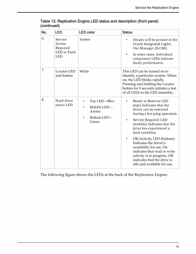
Table 12: Replication Engine LED status and description (front panel)(continued)No. LED LED color Status6 Service
ActionRequiredLED or FaultLED
Amber • Details will be present in theOracle Integrated LightsOut Manager (ILOM).
• In some cases, individualcomponent LEDs indicatefaulty performance.
7 Locator LEDand button
White This LED can be turned on toidentify a particular system. Whenon, the LED blinks rapidly.Pressing and holding the Locatorbutton for 5 seconds initiates a testof all LEDs in the LED assembly.
8 Hard drivestatus LED
• Top LED—Blue
• Middle LED—Amber
• Bottom LED—Green
• Ready to Remove LED(top): Indicates that thedriver can be removedduring a hot-plug operation.
• Service Required LED(middle): Indicates that thedrive has experienced afault condition.
• OK/Activity LED (bottom):Indicates the driver'savailabilty for use. Onindicates that read or writeactivity is in progress. Offindicates that the drive isidle and available for use.
The following figure shows the LEDs at the back of the Replication Engine:
Service the Replication Engine
76

Figure 36: Replication Engine back LEDs
Legend 1 Power supply status LEDs 2 Chassis status LEDs
3 Network management LED 4 Net0 to Net3 status LEDs
The following table provides information on the LEDS on the back of theReplication Engine:
Service the Replication Engine
77

Table 13: Replication Engine LED status and description (back panel)No. LED LED color Status1 Power
supplystatus LEDs
• (Top)OutputPower OKLED—Green
• (Middle)ServiceActionRequiredLED—Amber
• (Bottom)AC or DCInputPower OKLED—Green
• Output Power OK LED:Indicates that output power iswithout fault.
• Service Action Required LED:Indicates that service for thepower supply is required.
• AC or DC Input Power OKLED: Indicates that inputpower is without fault.
2 Chassisstatus LEDs
• (Left)LocatorLED andbutton—White
• (Center)ServiceActionRequiredLED—Amber
• (Right)Main PowerOK LED—Green
• Locator LED and button: TheLocator LED can be turned onto identify a particular system.
• Service Action Required LED:Indicates that service isrequired. Under some faultconditions, individualcomponent fault LEDs areturned on in addition to theService Action Required LED.
• Main Power OK LED: Indicatesthese conditions:
• Off: System is notrunning in its normalstate. System powermight be off. The SPmight be running.
• Steady on: System ispowered on and isrunning in its normaloperating state. Noservice actions arerequired.
Service the Replication Engine
78

Table 13: Replication Engine LED status and description (back panel)(continued)No. LED LED color Status
• Fast blink: System isrunning in standby modeand can be quicklyreturned to full function.
• Slow blink: A normal buttransitory activity istaking place. Slowblinking might indicatethat system diagnosticsare running or that thesystem is booting.
Service the Replication Engine
79

Table 13: Replication Engine LED status and description (back panel)(continued)No. LED LED color Status3 Network
managementLED
• (Left) LinkandActivityLED—Green
• (Right)Speed LED—Green,amber, oroff
Indicates these conditions:
• Link and Activity LED:• On or blinking: A link is
established.• Off: No link is
established.• Speed LED:
• On or blinking: The linkis operating as a 100-Mbps connection.
• Off : The link is operatingas a 10-Mbps connection.
4 Net0 to Net3status LEDs
• (Left) LinkandActivityLED—Green
• (Right)Speed LED—Amber
Indicates the state of the serviceprocessor:
• Link and Activity LED:• On or blinking: A link is
established.• Off: No link is
established.• Speed LED:
• Amber: The link isoperating as a Gigabitconnection (1000-Mbps).
• Green: The link isoperating as a 100-Mbpsconnection.
• Off: The link is operatingas a 10-Mbps connectionor there is no link.
Failed ComponentsA hardware component failure on an Oracle MaxRep Replication Engine can, insome instances, be detected directly on the hardware. Detailed information iscommunicated through the Call‑Home feature of the Oracle Integrated Lights
Service the Replication Engine
80

Out Manager (ILOM) that is active on the Pillar Axiom or Oracle FS Systemassociated with the Replication Engine.
Identify a Failed Hardware ComponentDepending on the physical component you are viewing, the way in which youidentify failed performance may be different.
1 To identify a failed power supply, observe the LEDs on the front panel ofthe system hardware.Possible LED status:
Off No service or action is required.
On (Amber) The power supply has failed and needs attention.
Note: Proceed with the following steps only when the power supply LEDis amber. The following steps determine whether the LED board has failed.
2 Press and hold the front panel Locator LED for 5 seconds.
3 Check whether all of the LEDs in the assembly are lit.
Yes The LED board is functional.
No The LED board has failed. View the ILOM for detailed information.
Identify a Failed Component in the ILOMAccess detailed information regarding the status of troubled components, andtheir specific location, in the configured Oracle Integrated Lights Out Manager(ILOM) user interface.
Prerequisite: Oracle Integrated Lights Out Manager
1 Log in to the Oracle ILOM GUI.
2 In the navigation pane, click Open Problems.
3 In the Open Problems list, identify Replication Engine components thatrequire attention.
4 Click System Information and navigate to the system area that requiresattention.
5 View the Health status and Health Details to obtain further informationabout the failed system components.
Note: View additional details about the hardware, including componentlocations, in the component Details column.
Successful Component ReplacementAfter replacing a failed hardware component, verify that the replacementinstallation procedure was successful. You can verify the status of the installation
Service the Replication Engine
81

by checking the LEDs on the Replication Engine or by logging in to the OracleIntegrated Lights Out Manager (ILOM).
Verify Component Replacement of the HardwareGain instant knowledge regarding successful installation of replacementhardware by viewing the LED assembly located on the front and back of theReplication Engine.
1 View the LED assembly on the front panel of the Replication Engine andverify that all LEDs are lit at their normal state.
Note: If the LEDs in the assembly are not lit at their normal state, identifythe faulted area by referencing the front panel LED indicators, or log in tothe ILOM to view detailed information.
2 View the LED assembly on the back panel of the Replication Engine andverify that all LEDs are lit at their normal state.
Note: If the LEDs in the assembly are not lit at their normal state, identifythe faulted area by referencing the back panel LED indicators, or log in tothe ILOM to view detailed information.
Verify Component Replacement in the ILOMVerify that the replacement of failed hardware on the Replication Engine wassuccessful by viewing information about the Replication Engine in the OracleIntegrated Lights Out Manager.
Prerequisite: Oracle Integrated Lights Out Manager
1 Log in to the Oracle ILOM GUI.
2 In the navigation pane, click Open Problems.
3 View items in the Open Problems list to identify Replication Enginecomponents that require attention.
Note: If no items are present in the Open Problems list, your componentshave been replaced and installed correctly.
Power Down the Replication EnginePower down a Replication Engine prior to performing the required maintenanceservice on parts that are not hot-serviceable.
Prerequisites: • Access to the Oracle MaxRep for SAN GUI
• Access to the Oracle Support User Interface (UI)
Note: Powering down should only be executed from a MaxRep 3 ReplicationEngine that is either running the control services, or that is part of a clusteredhigh availability (HA) pair.
Service the Replication Engine
82

1 From an Internet browser, log in to the Oracle MaxRep for SAN GUI.
2 Navigate to Monitor > Protection Health to note the current status of theprotection plans running on the system.
3 Navigate to Monitor > Control Service/Process Service Health to note thecurrent status of the control service Engine and process service Enginesrunning on the system.
Note: Noting the status of the protection plan health and the health of thecontrol service Engine and the process service Engines helps you toobserve the current state of the operating systems prior to powering downthe Replication Engine.
4 From a new tab in an Internet browser, log in to the Oracle Support UI ofeither the MaxRep Replication Engine that is running the control services,or that is part of the HA cluster IP.You can navigate to the appropriate Support UI by going to either http://enginename (where enginename is the name of the MaxRep ReplicationEngine that is running the control services), or to engineIPaddress/support(where engineIPaddress is the IP address of the engine that is part of the HAcluster).
5 Navigate to Management Tasks > Shutdown/Restart Services.
6 Click the Host drop-down menu, and select the Replication Engine thatyou want to power down.
7 From the Action options, select Shutdown.
8 Click Save Task.The UI screen will present a task list, and the Replication Engine shutdownstatus will show as Pending for about one minute. The UI screen will thenupdate the Replication Engine status to In Progress. As the shutdowncompletes, the UI will shut down as well. Replication Engine serviceactions can now take place.
Note: In the Oracle FS System Manager GUI, the Overall System Status willchange to Warning to communicate that the MaxRep Engine is poweringdown.
9 If you need to remove the Replication Engine from the rack, power off thePDU circuit breakers to stop power, and disconnect power cables from theReplication Engine.You can now perform the service actions that are required.
You will regain access to the UI once the hardware service is complete, and theReplication Engine is powered back on.
Service the Replication Engine
83
Power Up the Replication Engine After ServicePower up a Replication Engine after the required maintenance service on parts iscomplete. Resync all replication protection plans from the Oracle MaxRep forSAN GUI.
Prerequisite: Access to the Oracle MaxRep for SAN GUI
1 Reattach the power cables to the Replication Engine, and plug the cablesinto a power source.
2 Power on the PDU circuit breakers to restore power to the ReplicationEngine.The LEDs will turn green, signaling that the Replication Engine is poweredon. The Engine may take a few minutes to reboot.
3 Log in to the Oracle MaxRep for SAN GUI.4 Navigate to Monitor > Protection Health > Plan Health to view replication
protection plans.5 Select the first replication protection plan to perform a resync.6 Click Manage Protection Plan.7 Locate the replication protection plan that you want to resync and navigate
to Action > Modify.8 From the Restart Resync option, select Click Here.9 Click Restart Resync, then click OK.10 Repeat Steps 4-9 for all remaining replication protection plans.11 Navigate to Monitor > Protection Health > Plan Health to verify that all
replication plans are in sync.Replication plans that have resynced successfully will show a green squarenext to the plan name.
Replication Engine Service ProceduresThe Oracle MaxRep Replication Engine consists of several replaceablecomponents. Many Replication Engine components are customer replaceableunits (CRUs), while others are field replaceable units (FRUs) that require OracleCustomer Support to perform the replacement. Also, some components are hot-serviceable, meaning that they can be replaced while the Replication Engine ispowered on. Some of the Replication Engine component replacement proceduresrequire the Replication Engine to be powered off and/or removed from the rack.
When replacing a Replication Engine CRU or FRU, you must know its partnumber and whether it is hot serviceable. Having that information helps you toorder the correct replacement component and to determine whether you canreplace the component yourself.
To locate part numbers, open Oracle System Handbook (https://support.oracle.com/ handbook_partner/index.html) and go to Current Systems,
Service the Replication Engine
84

and select Oracle MaxRepReplication Engine under Disk Arrays. Part numbersare listed in the components list.
Some FRUs and CRUs can be accessed from the front or back of the ReplicationEngine. For replacing other FRUs and CRUs, you must open the top cover of theReplication Engine. The following table provides a summary of the ReplicationEngine FRUs and CRUs.
Table 14: Replication Engine replaceable components
Replication Engine component Type Hotserviceable
Access requirements
Air filter CRU Yes Front access
Fan module CRU No Remove top cover
Power supply CRU Yes Rear access
Drives CRU Yes Front access
Riser board assembly CRU No Remove top cover
HBA CRU No Remove top cover
DIMM CRU No Remove top cover
Disk backplane FRU No Remove top cover
Heat sink FRU No Remove top cover
CPU FRU No Remove top cover
LED alarm assembly FRU No Remove top cover
Motherboard FRU No Remove top cover
Motherboard cables FRU No Remove top cover
Power distribution board(PDB)
FRU No Remove top cover
The following figure shows an exploded view of all the replaceable componentsof the Replication Engine:
Service the Replication Engine
85
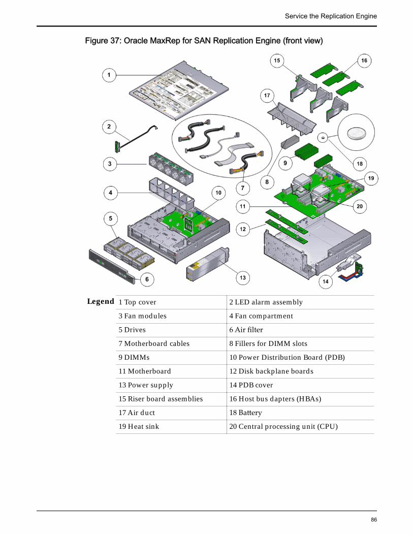
Figure 37: Oracle MaxRep for SAN Replication Engine (front view)
Legend 1 Top cover 2 LED alarm assembly
3 Fan modules 4 Fan compartment
5 Drives 6 Air filter
7 Motherboard cables 8 Fillers for DIMM slots
9 DIMMs 10 Power Distribution Board (PDB)
11 Motherboard 12 Disk backplane boards
13 Power supply 14 PDB cover
15 Riser board assemblies 16 Host bus dapters (HBAs)
17 Air duct 18 Battery
19 Heat sink 20 Central processing unit (CPU)
Service the Replication Engine
86

Related LinksReplace a Replication Engine Air FilterReplace a Replication Engine Fan ModuleReplace a Replication Engine Power SupplyReplace a Replication Engine DriveReplace a Replication Engine RiserReplace a Replication Engine HBAReplace a Replication Engine DIMMReplace a Replication Engine Disk BackplaneReplace a Replication Engine CPUReplace a Replication Engine LED Alarm AssemblyReplace a Replication Engine MotherboardReplace Replication Engine Motherboard CablesReplace a Replication Engine Power Distribution BoardReplace a Replication Engine Heat Sink
Replace a Replication Engine Air FilterAir filters are designed to maintain proper airflow within the Replication Engineby keeping the air circulating inside the chassis clear and free of dust.
Each Replication Engine has an air filter covering the front of the chassis. Airfilters are customer replaceable units (CRUs). Replacing the air filter does notrequire you to bring the Replication Engine offline. The following figure showsthe Replication Engine air filter.
Figure 38: Replication Engine air filter
Procedure Overview
1 Remove an Air Filter
2 Insert an Air Filter
Remove an Air Filter
Service the Replication Engine
87
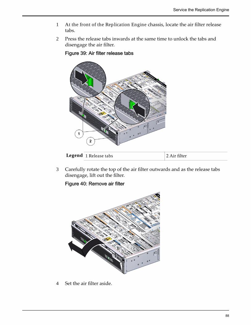
1 At the front of the Replication Engine chassis, locate the air filter releasetabs.
2 Press the release tabs inwards at the same time to unlock the tabs anddisengage the air filter.
Figure 39: Air filter release tabs
Legend 1 Release tabs 2 Air filter
3 Carefully rotate the top of the air filter outwards and as the release tabsdisengage, lift out the filter.
Figure 40: Remove air filter
4 Set the air filter aside.
Service the Replication Engine
88

Insert an Air Filter
1 Tilt the top of the air filter slightly towards you and insert the bottom twohooks into the mounting tabs.
Figure 41: Insert air filter
Important: Ensure that nothing interferes with the edges of the air filter andthat the air filter seats properly.
2 Press the top corners of the air filter to engage the top two air filter hookswith the top rail tabs.
3 Press both air filter release tabs until they lock in place.
Replace a Replication Engine Fan ModuleIf a fan module fails, the system issues critical alerts. Replace failed fan modulesas soon as possible.
Prerequisites: • Ensure that you have a Phillips Number 2 screwdriverwith at least a 4-inch shaft.
• Before handling a component, touch a grounded surface todischarge any static electricity.
• Attach an electrostatic discharge (ESD) wrist strap to yourwrist, and stand on an ESD mat while replacingcomponents.
• Deploy any rack anti-tilt mechanism before releasing therelease buttons and extending the Replication Enginechassis.
Each Replication Engine has five fan modules that are located side-by-side at thecenter inside the Replication Engine chassis. A fan module is a customerreplaceable unit (CRU). Replacing a fan module requires you to bring the
Service the Replication Engine
89

Replication Engine offline. The following figure shows a Replication Engine fanmodule.
Figure 42: Fan module
Figure 43: Fan module location
Legend 1 Fan module-0 2 Fan module-1
3 Fan module-2 4 Fan module-3
5 Fan module-4
Note: The fan modules can be accessed only after removing the top cover overthe Replication Engine chassis.
Note: To replace a fan module, you do not need to remove the Replication Enginefrom the rack but extend it along the Replication Engine rails using the cablemanagement arm (CMA).
Note: Ensure that all power is removed from the Replication Engine beforereplacing the fan module. Disconnect the power cables before performing the fanmodule replacement procedure.
Service the Replication Engine
90

Note: For fan replacement, the Replaceable Unit list displays the names of eachfan. Each power supply contains one fan, and each fan module contains two fans.If a fan fails in a power supply, replace the power supply. If a fan fails in a fanmodule, replace the fan module. The following list identifies the names of thefans and the corresponding customer replaceable unit (CRU).
If the following fan fails Replace the following CRUFan 0 Power supply 0Fan 1 Power supply 1Fans 2, 3 Fan module 0Fans 4, 5 Fan module 1Fans 6, 7 Fan module 2Fans 8, 9 Fan module 3Fans 10, 11 Fan module 4
Procedure Overview
1 Slide Replication Engine to Service Position
2 Remove the Replication Engine Power Supply Cords
3 Open the Replication Engine Top Cover
4 Remove a Fan Module
5 Insert a Fan Module
6 Close the Replication Engine Top Cover
7 Complete the Component Replacement
Remove the Replication Engine Power Supply Cords
Disconnect the power cords from both power supplies.
Figure 44: Remove power supply cords
Service the Replication Engine
91

Legend 1 Power supply cords
2 Power supply handle
Tip: Always notify affected users that the Replication Engine will bepowered off.
Slide Replication Engine to Service Position
Squeeze the release buttons on either side of the Replication Engine frontpanel at the same time and slide the Replication Engine chassis forwarduntil the slide rails lock into position. You might have to remove screwslocking the front panel to the rack before the Replication Engine slidesforward.
Caution: Deploy any rack anti-tilt mechanism before releasing the releasebuttons and extending the Replication Engine chassis.
Figure 45: Slide the Replication Engine to service position
Legend 1 Rack
2 Replication Engine chassis
3 Release buttons
Service the Replication Engine
92

Important: Before you slide the Replication Engine chassis out, ensure thatthe cables do not interfere with the movement of the Replication Enginechassis. Although the cable management arm (CMA) is hinged so that youcan extend the Replication Engine chassis, all cables and cords must be outof the way when you service the Replication Engine components.
Open the Replication Engine Top Cover
1 Fully loosen the two captive thumb screws at the back of the top coverusing the Phillips number 2 screwdriver, if necessary.
Figure 46: Captive thumb screws to remove the top cover
Legend 1 Replication Engine top cover
2 Captive screws
2 Slide the top cover backwards 0.5 inches (13 mm) and lift the top coverstraight up and off the Replication Engine chassis.
Remove a Fan Module
1 Using your thumb and forefinger, grasp the removal tab and gently lift thefan module from the fan compartment.
Service the Replication Engine
93
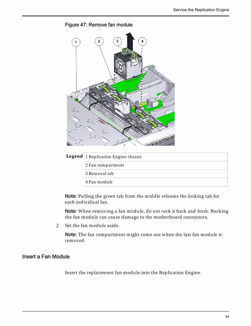
Figure 47: Remove fan module
Legend 1 Replication Engine chassis
2 Fan compartment
3 Removal tab
4 Fan module
Note: Pulling the green tab from the middle releases the locking tab foreach individual fan.
Note: When removing a fan module, do not rock it back and forth. Rockingthe fan module can cause damage to the motherboard connectors.
2 Set the fan module aside.
Note: The fan compartment might come out when the last fan module isremoved.
Insert a Fan Module
Insert the replacement fan module into the Replication Engine.
Service the Replication Engine
94

Figure 48: Insert fan module
Legend 1 Replication Engine chassis
2 Fan compartment
3 Fan module
Note: Press down on the fan module and apply firm pressure to fully seatthe fan module into the fan compartment. The fan modules are notched toensure that they are installed in the correct orientation.
Note: Repeat for each additional fan module.
Close the Replication Engine Top Cover
Place the top cover of the Replication Engine and tighten the two thumbscrews at the back of the Replication Engine that secure the top cover.
Service the Replication Engine
95
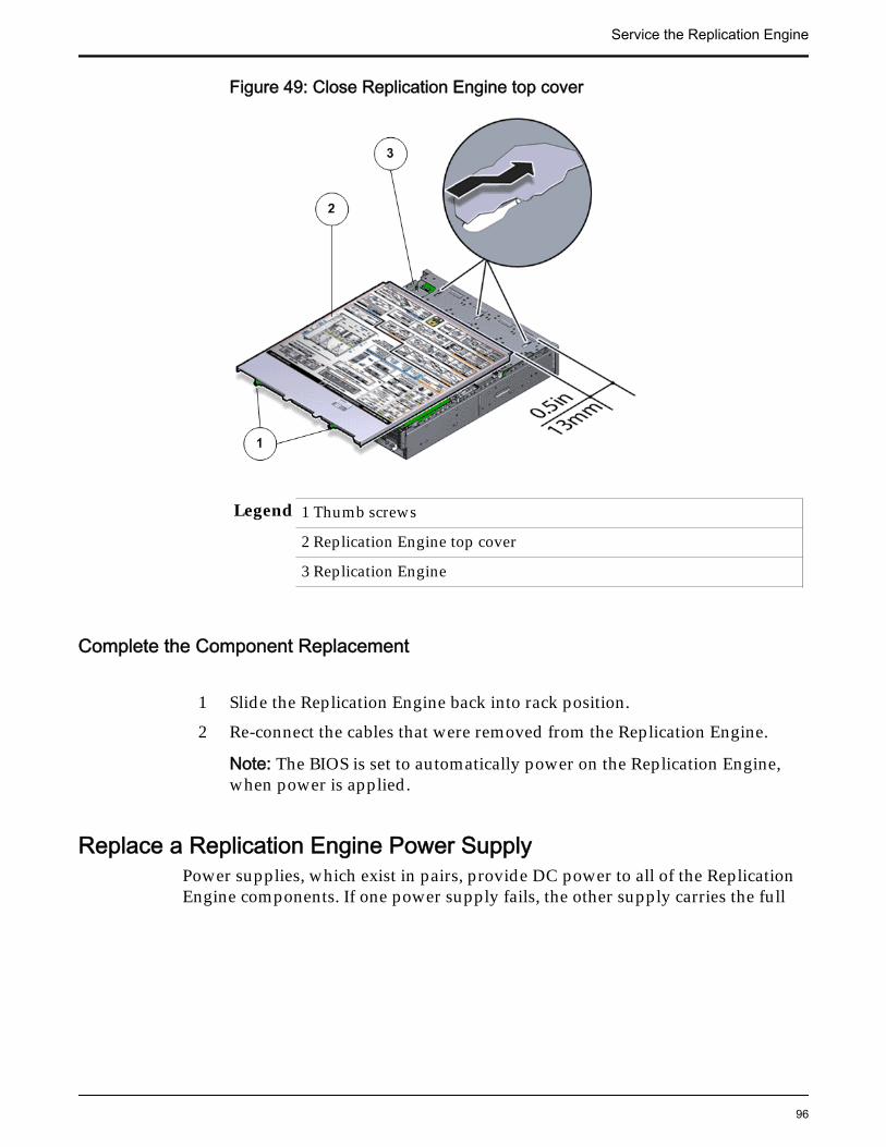
Figure 49: Close Replication Engine top cover
Legend 1 Thumb screws
2 Replication Engine top cover
3 Replication Engine
Complete the Component Replacement
1 Slide the Replication Engine back into rack position.
2 Re-connect the cables that were removed from the Replication Engine.
Note: The BIOS is set to automatically power on the Replication Engine,when power is applied.
Replace a Replication Engine Power SupplyPower supplies, which exist in pairs, provide DC power to all of the ReplicationEngine components. If one power supply fails, the other supply carries the full
Service the Replication Engine
96

load. This situation creates a risk of Replication Engine failure should the otherpower supply also fail.
Prerequisites: • Deploy any rack anti-tilt mechanism before releasingthe release buttons and extending the ReplicationEngine.
• Before handling a component, touch a groundedsurface to discharge any static electricity.
• Attach an electrostatic discharge (ESD) wrist strap toyour wrist, and stand on an ESD mat while replacingcomponents.
• Make sure you have a similar replacement powersupply available before you start the replacementprocedure.
Each Replication Engine has a pair of power supplies that are located at the backof the Replication Engine. Power supplies are customer replaceable units (CRUs).Replacing a power supply does not require you to bring the Replication Engineoffline, provided that the other power supply is online and working. Thefollowing figure identifies the location of the Replication Engine power supplies.
Figure 50: Power supply location
Legend 1 Power supply-1 (PS-1)
2 Power supply-0 (PS-0)
Note: To replace a power supply, you can access the faulted power supply fromthe back of the Replication Engine module. To access the power supply located inthe bottom slot (PS-0), the CMA clip must be disconnected to enable the powersupply to clear the support arm.
Note: Replacing the power supply does not require you to slide the ReplicationEngine into the extended rack position and can be performed while theReplication Engine is in the rack position.
Service the Replication Engine
97

Note: Ensure that the power strain relief strap on the power supply is positionedcorrectly such that there is proper clearance and the power supplies can be re-inserted into the power supply compartment without interference.
Note: Ensure that the power cable is routed correctly and there is no interferencewith the Replication Engine chassis.
Important: Do not remove the failed power supply until you have a replacementpower supply to ensure proper airflow in the Replication Engine.
Note: For fan replacement, the Replaceable Unit list displays the names of eachfan. Each power supply contains one fan, and each fan module contains two fans.If a fan fails in a power supply, replace the power supply. If a fan fails in a fanmodule, replace the fan module. The following list identifies the names of thefans and the corresponding customer replaceable unit (CRU).
If the following fan fails Replace the following CRUFan 0 Power supply 0Fan 1 Power supply 1Fans 2, 3 Fan module 0Fans 4, 5 Fan module 1Fans 6, 7 Fan module 2Fans 8, 9 Fan module 3Fans 10, 11 Fan module 4
Procedure Overview
1 Remove the Power Cord
2 Remove a Power Supply
3 Insert a Power Supply
4 Insert the Power Cord
Remove the Power Cord
Disconnect the power cord from the power supply.
Service the Replication Engine
98

Figure 51: Disconnect the power cord
Legend 1 Power supply cord
2 Power supply handle
Remove a Power Supply
1 Remove the power supply by grasping the power supply handle andpushing the power supply latch to the left.
Figure 52: Replication Engine power supply latch
Legend 1 Power supply handle 3 Power supply
2 Power supply latch 4 Replication Engine back
Service the Replication Engine
99

Figure 53: Remove power supply
Legend 1 Power supply
2 Power supply compartment
3 Replication Engine
2 If both power supplies must be removed, label the power supplies with theslot numbers from which they are removed.
Note: Removing both power supplies will result in the immediatepowering off of the Replication Engine. Do not pull both power suppliesfrom an active and running Replication Engine.
Note: The power supplies must be reinstalled into the same slots fromwhich they were removed.
3 Pull the power supply out of the chassis and place it on an antistatic mat.
Insert a Power Supply
1 Slide the replacement power supply into the power supply compartment atthe back of the Replication Engine until it is fully seated.
Service the Replication Engine
100

Figure 54: Insert power supply
Legend 1 Power supply
2 Power supply compartment
3 Replication Engine chassis
2 Listen for an audible click or feel the power supply engage to confirm thatthe power supply is properly seated.
Note: Repeat for each power supply. Also, replace the power supplies onlyinto the slots from which they had been removed.
Insert the Power Cord
Connect the power cord to the power supply.
Replace a Replication Engine DriveEach drive in a Replication Engine is RAID 1 mirror protected with an alternatedrive. If a failed drive is not replaced, you run the risk of losing the data if themirrored drive also fails. A failed drive must be replaced as soon as possible toavoid the risk of data loss and to restore system performance.
Prerequisites: • Before handling a component, touch a grounded surface todischarge any static electricity.
• Attach an electrostatic discharge (ESD) wrist strap to yourwrist, and stand on an ESD mat while replacingcomponents.
• Ensure that a replacement drive or a filler panel availableto replace the drive that you will be removing.
Service the Replication Engine
101

Drives are customer replaceable units (CRUs). The following figure shows thelocation of the drives.
Figure 55: Drive
Note: To replace an drive, you do not need to remove the Replication Enginefrom the rack or even extend it along the Replication Engine rails.
Note: Make a note of the drive slot where the failed drive was located so that thereplacement drive can be placed in the same slot to avoid the risk of mis-configuration. Alternatively, replace the drives only one at a time, so that there isonly one empty drive slot at any point in time. Replacing the incorrect drivewhen a drive is failed is likely to cause loss of data and an extended outage.
Procedure Overview
1 Remove an Air Filter
2 Remove a Replication Engine Drive
3 Insert a Replication Engine Drive
4 Insert an Air Filter
Remove an Air Filter
1 At the front of the Replication Engine chassis, locate the air filter releasetabs.
2 Press the release tabs inwards at the same time to unlock the tabs anddisengage the air filter.
Service the Replication Engine
102

Figure 56: Air filter release tabs
Legend 1 Release tabs 2 Air filter
3 Carefully rotate the top of the air filter outwards and as the release tabsdisengage, lift out the filter.
Figure 57: Remove air filter
4 Set the air filter aside.
Remove a Replication Engine Drive1 Remove the Replication Engine drive from the drive compartment by
pushing the latch release button to open the latch.
Service the Replication Engine
103

Figure 58: Open drive latch
Legend 1 Drive 2 Latch release button
3 Replication Engine front
Important: Do not bend the latch too far to the right. Bending the latch candamage the latch.
Important: For drives that are removed but will be later reinserted, label thedrive with the position that the drive occupies in the Replication Engine.Reinserting drives in the incorrect slot might result in data loss and a fullrecovery might be required to resume operation.
2 Grasp the latch and pull the drive out of the Replication Engine drivecompartment.
Figure 59: Remove drive
Legend 1 Drive 2 Replication Engine drive compartment
3 Replication Engine front
Service the Replication Engine
104

3 Repeat for each of the four drives of the Replication Engine that need to bereplaced.
Insert a Replication Engine Drive1 Unpack the component from its shipping carton.
Note: Place the component on an antistatic mat if it must be set aside forany reason.
2 Insert the drive into the correct slot.
Figure 60: Insert drive
Legend 1 Drive
2 Replication Engine drive compartment
3 front
Note: The Replication Engine might have filler panels covering the emptyslots in the drive compartment.
3 Slide the replacement drive into the drive compartment until the drive isfully seated into the slot.
Note: Be sure to install the replacement drive in the same slot from whichthe failed drive was removed.
4 Close the drive carrier latch to lock the drive in place.
Service the Replication Engine
105
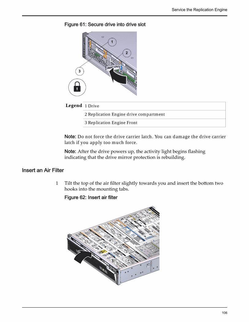
Figure 61: Secure drive into drive slot
Legend 1 Drive
2 Replication Engine drive compartment
3 Replication Engine Front
Note: Do not force the drive carrier latch. You can damage the drive carrierlatch if you apply too much force.
Note: After the drive powers up, the activity light begins flashingindicating that the drive mirror protection is rebuilding.
Insert an Air Filter
1 Tilt the top of the air filter slightly towards you and insert the bottom twohooks into the mounting tabs.
Figure 62: Insert air filter
Service the Replication Engine
106
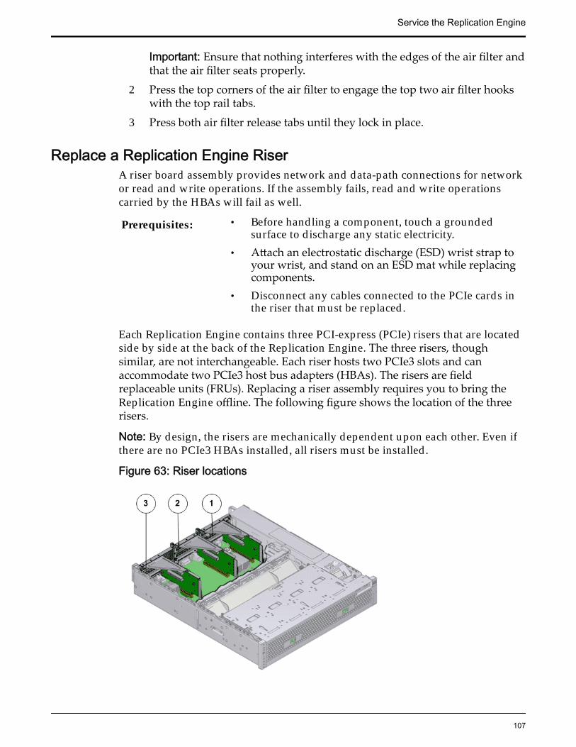
Important: Ensure that nothing interferes with the edges of the air filter andthat the air filter seats properly.
2 Press the top corners of the air filter to engage the top two air filter hookswith the top rail tabs.
3 Press both air filter release tabs until they lock in place.
Replace a Replication Engine RiserA riser board assembly provides network and data-path connections for networkor read and write operations. If the assembly fails, read and write operationscarried by the HBAs will fail as well.
Prerequisites: • Before handling a component, touch a groundedsurface to discharge any static electricity.
• Attach an electrostatic discharge (ESD) wrist strap toyour wrist, and stand on an ESD mat while replacingcomponents.
• Disconnect any cables connected to the PCIe cards inthe riser that must be replaced.
Each Replication Engine contains three PCI-express (PCIe) risers that are locatedside by side at the back of the Replication Engine. The three risers, thoughsimilar, are not interchangeable. Each riser hosts two PCIe3 slots and canaccommodate two PCIe3 host bus adapters (HBAs). The risers are fieldreplaceable units (FRUs). Replacing a riser assembly requires you to bring theReplication Engine offline. The following figure shows the location of the threerisers.
Note: By design, the risers are mechanically dependent upon each other. Even ifthere are no PCIe3 HBAs installed, all risers must be installed.
Figure 63: Riser locations
Service the Replication Engine
107

Legend 1 Riser 1
2 Riser 2
3 Riser 3 with latch
Note: The risers can be accessed only after removing the top cover over theReplication Engine chassis.
Note: To replace a riser, you do not need to remove the Replication Engine fromthe rack but extend it along the Replication Engine rails using the cablemanagement arm (CMA).
Note: Ensure that all power is removed from the Replication Engine beforereplacing the riser. Disconnect the power cords before performing the riserreplacement procedure.
Procedure Overview
1 Slide Replication Engine to Service Position
2 Remove the Replication Engine Power Supply Cords
3 Disconnect Replication Engine Cabling
4 Open the Replication Engine Top Cover
5 Remove a Riser
6 Insert a Riser
7 Close the Replication Engine Top Cover
8 Reconnect Replication Engine Cabling
9 Complete the Component Replacement
Remove the Replication Engine Power Supply Cords
Disconnect the power cords from both power supplies.
Service the Replication Engine
108

Figure 64: Remove power supply cords
Legend 1 Power supply cords
2 Power supply handle
Tip: Always notify affected users that the Replication Engine will bepowered off.
Slide Replication Engine to Service Position
Squeeze the release buttons on either side of the Replication Engine frontpanel at the same time and slide the Replication Engine chassis forwarduntil the slide rails lock into position. You might have to remove screwslocking the front panel to the rack before the Replication Engine slidesforward.
Caution: Deploy any rack anti-tilt mechanism before releasing the releasebuttons and extending the Replication Engine chassis.
Service the Replication Engine
109

Figure 65: Slide the Replication Engine to service position
Legend 1 Rack
2 Replication Engine chassis
3 Release buttons
Important: Before you slide the Replication Engine chassis out, ensure thatthe cables do not interfere with the movement of the Replication Enginechassis. Although the cable management arm (CMA) is hinged so that youcan extend the Replication Engine chassis, all cables and cords must be outof the way when you service the Replication Engine components.
Disconnect Replication Engine CablingDisconnect all data cables from the Replication Engine.
Note: All cables must be disconnected from the Replication Engine andlabeled such that they can be reconnected accurately to the ReplicationEngine after the replacement procedure is complete. Reconnecting cablesto the incorrect position might impact the performance of the ReplicationEngine or result in a complete loss of functionality.
Note: Service the Replication Engine components from the front of theReplication Engine while the Replication Engine is in service position.
Service the Replication Engine
110

Note: Do not lean on or place any weight on the Replication Engine whilethe Replication Engine is in the service position.
Open the Replication Engine Top Cover
1 Fully loosen the two captive thumb screws at the back of the top coverusing the Phillips number 2 screwdriver, if necessary.
Figure 66: Captive thumb screws to remove the top cover
Legend 1 Replication Engine top cover
2 Captive screws
2 Slide the top cover backwards 0.5 inches (13 mm) and lift the top coverstraight up and off the Replication Engine chassis.
Remove a Riser
1 Disconnect any external cables that remain connected to the HBAs in therisers.
Note: Also disconnect any internal cables attached to the HBAs, if that willease removing the HBA.
Tip: Make a note of the positions of all existing cable connections beforeremoving any cables. Replacing HBAs or their cables into the incorrectposition in the riser may result in a loss of performance or functionality.
2 Note the position of the HBAs installed on the riser.
Tip: Make a note of the slot numbers of all existing HBAs before removingany HBAs.
Service the Replication Engine
111

3 Using a Phillips Number 2 screwdriver, loosen the two Phillips Number 2captive screws on either side of the riser that hold the riser to theReplication Engine motherboard.
Note: The riser on the opposite end of the power supply has a latch thatmust be disengaged to remove the riser from the Replication Enginechassis
Figure 67: Captive screws to secure the risers
Legend 1 Riser 3 with latch 3 Riser 1
2 Riser 2 4 Captive screws that secure riser
To remove riser 3, unlock the latch to release the riser from the ReplicationEngine motherboard.
Service the Replication Engine
112

Figure 68: Unlock Riser 3 latch
Legend 1 Riser 3 latch 3 HBA
2 Riser 3
4 Carefully pull the riser straight up and place it aside.
Figure 69: Remove riser
Legend 1 Riser
2 Replication Engine motherboard
Service the Replication Engine
113
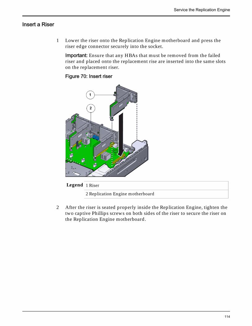
Insert a Riser
1 Lower the riser onto the Replication Engine motherboard and press theriser edge connector securely into the socket.
Important: Ensure that any HBAs that must be removed from the failedriser and placed onto the replacement rise are inserted into the same slotson the replacement riser.
Figure 70: Insert riser
Legend 1 Riser
2 Replication Engine motherboard
2 After the riser is seated properly inside the Replication Engine, tighten thetwo captive Phillips screws on both sides of the riser to secure the riser onthe Replication Engine motherboard.
Service the Replication Engine
114
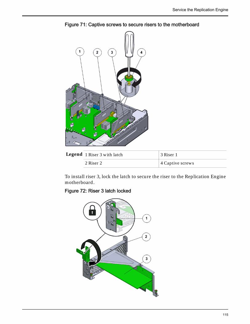
Figure 71: Captive screws to secure risers to the motherboard
Legend 1 Riser 3 with latch 3 Riser 1
2 Riser 2 4 Captive screws
To install riser 3, lock the latch to secure the riser to the Replication Enginemotherboard.
Figure 72: Riser 3 latch locked
Service the Replication Engine
115

Legend 1 Riser 3 latch 3 HBA
2 Riser 3
3 Reconnect any previously removed internal or external cables to any HBAsinstalled in the riser.
4 Repeat the above steps for any additional risers that you are installing.
Close the Replication Engine Top Cover
Place the top cover of the Replication Engine and tighten the two thumbscrews at the back of the Replication Engine that secure the top cover.
Figure 73: Close Replication Engine top cover
Legend 1 Thumb screws
2 Replication Engine top cover
3 Replication Engine
Reconnect Replication Engine Cabling
1 Reconnect all the data cables on the Replication Engine.
Service the Replication Engine
116

Note: Oracle Customer Support recommends labeling all cables connectedto the Replication Engine so that the cables can be reconnected accuratelyto the Replication Engine after the replacement procedure is complete.
2 Reconnect the CMA to the Replication Engine by attaching the release tabon the left and right side of the CMA.
Complete the Component Replacement
1 Slide the Replication Engine back into rack position.
2 Re-connect the cables that were removed from the Replication Engine.
Note: The BIOS is set to automatically power on the Replication Engine,when power is applied.
Replace a Replication Engine HBAAn HBA is a circuit board installed inside the Replication Engine riser boardassembly.
HBAs are installed in pairs in a Replication Engine to ensure that multiple datapaths are available to the source or target storage. In the event of a failed HBA,the alternate HBA receives additional load. If the second HBA fails, the resultwould be a loss of replication services. To avoid the loss of service, an HBAshould be replaced as soon as possible if a failure has been identified.
Prerequisites: • Ensure that you have a Phillips Number 2screwdriver with at least a 4-inch shaft.
• Before handling a component, touch a groundedsurface to discharge any static electricity.
• Attach an electrostatic discharge (ESD) wrist strap toyour wrist, and stand on an ESD mat while replacingcomponents.
• Keep filler panels available in case you only removethe HBA and do not plan to replace the HBAimmediately.
Note: Filler panels ensure proper airflow inside theReplication Engine.
• Use only the filler panels provided with theReplication Engine to maintain proper airflow andEMI conformance for empty slots inside theReplication Engine.
• Label all cables connected to the Replication Engineso that they can be reconnected accurately to the
Service the Replication Engine
117

Replication Engine after the replacement procedure iscomplete.
Note: Replacing an HBA might require changes to the port’s world wide name(WWN).
Each Oracle Flash Storage System supports two types of HBA connectivity SAN(FC or iSCSI HBA 16Gb, optical only) and NAS (10 GbE HBA). The placement ofthe HBA inside the riser slot is based on the Oracle FS System configurationoption selected. All HBAs supported in the Oracle FS System are customerreplaceable units (CRUs). Replacement of an HBA requires you to bring theReplication Engine offline. HBAs connecting to host servers must be placed intoslots 1, 4, and 5 on the risers. HBAs connecting to Drive Enclosures must beplaced into slots 2, 3, and 6 on the risers. You must install all HBAs according tothe slot numbers listed in the following table.
The Oracle MaxRep Replication Engine supports the following HBA options:
Table 15: Supported HBAs on the Replication Engine
HBA Quantity and slot
8 Gb/s dual-port Fibre Channel (FC)QLogic
Two in slots 3 and 6
10 Gb/s dual-port Ethernet RJ45 Two in slots 2 and 5
10 Gb/s dual-port Ethernet copper or fibreSFP+
Three in slots 2, 4, and 5
Note: A Replication Engine can support either two 10 Gb/s dual-port EthernetRJ45 HBAs or three 10 Gb/s dual-port Ethernet copper or fibre SFP+ HBAs.
The following figure shows the 8 Gb/s dual-port Fibre Channel (FC) QLogicHBA.
Figure 74: 8 Gb/s dual-port Fibre Channel (FC) QLogic HBA
The following figure shows the 10 Gb/s dual-port Ethernet RJ45 HBA.
Service the Replication Engine
118

Figure 75: 10 Gb/s dual-port Ethernet RJ45 HBA
The following figure shows the 10 Gb/s dual-port Ethernet copper or fiber SFP+HBA.
Figure 76: 10 Gb/s dual-port Ethernet copper or fiber SFP+ HBA
Note: The risers and HBAs can be accessed only after removing the top coverover the Replication Engine chassis.
Note: To replace an HBA, you do not need to remove the Replication Enginefrom the rack but extend it along the Replication Engine rails using the cablemanagement arm (CMA).
Note: Ensure that all power is removed from the Replication Engine beforereplacing the riser. Disconnect the power cords before performing the fanmodule replacement procedure.
Note: For FC HBA replacements, Oracle Customer Support is required to enablethe replacement HBA for use in the system. Oracle recommends scheduling thisprior to replacing the HBA.
Procedure Overview
1 Slide Replication Engine to Service Position
2 Remove the Replication Engine Power Supply Cords
3 Disconnect Replication Engine Cabling
4 Open the Replication Engine Top Cover
5 Remove a Riser
Service the Replication Engine
119
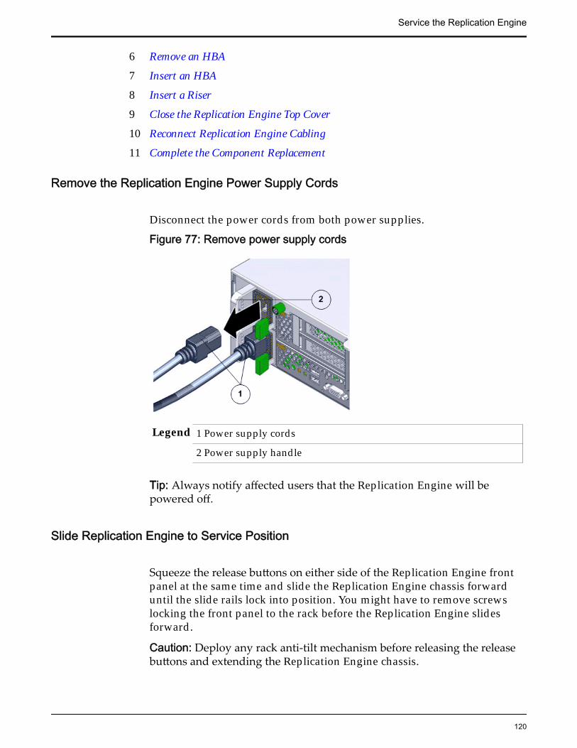
6 Remove an HBA
7 Insert an HBA
8 Insert a Riser
9 Close the Replication Engine Top Cover
10 Reconnect Replication Engine Cabling
11 Complete the Component Replacement
Remove the Replication Engine Power Supply Cords
Disconnect the power cords from both power supplies.
Figure 77: Remove power supply cords
Legend 1 Power supply cords
2 Power supply handle
Tip: Always notify affected users that the Replication Engine will bepowered off.
Slide Replication Engine to Service Position
Squeeze the release buttons on either side of the Replication Engine frontpanel at the same time and slide the Replication Engine chassis forwarduntil the slide rails lock into position. You might have to remove screwslocking the front panel to the rack before the Replication Engine slidesforward.
Caution: Deploy any rack anti-tilt mechanism before releasing the releasebuttons and extending the Replication Engine chassis.
Service the Replication Engine
120
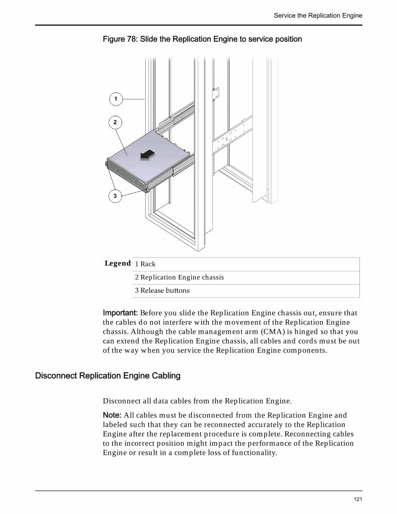
Figure 78: Slide the Replication Engine to service position
Legend 1 Rack
2 Replication Engine chassis
3 Release buttons
Important: Before you slide the Replication Engine chassis out, ensure thatthe cables do not interfere with the movement of the Replication Enginechassis. Although the cable management arm (CMA) is hinged so that youcan extend the Replication Engine chassis, all cables and cords must be outof the way when you service the Replication Engine components.
Disconnect Replication Engine Cabling
Disconnect all data cables from the Replication Engine.
Note: All cables must be disconnected from the Replication Engine andlabeled such that they can be reconnected accurately to the ReplicationEngine after the replacement procedure is complete. Reconnecting cablesto the incorrect position might impact the performance of the ReplicationEngine or result in a complete loss of functionality.
Service the Replication Engine
121

Note: Service the Replication Engine components from the front of theReplication Engine while the Replication Engine is in service position.
Note: Do not lean on or place any weight on the Replication Engine whilethe Replication Engine is in the service position.
Open the Replication Engine Top Cover
1 Fully loosen the two captive thumb screws at the back of the top coverusing the Phillips number 2 screwdriver, if necessary.
Figure 79: Captive thumb screws to remove the top cover
Legend 1 Replication Engine top cover
2 Captive screws
2 Slide the top cover backwards 0.5 inches (13 mm) and lift the top coverstraight up and off the Replication Engine chassis.
Remove a Riser
1 Disconnect any external cables that remain connected to the HBAs in therisers.
Note: Also disconnect any internal cables attached to the HBAs, if that willease removing the HBA.
Tip: Make a note of the positions of all existing cable connections beforeremoving any cables. Replacing HBAs or their cables into the incorrectposition in the riser may result in a loss of performance or functionality.
2 Note the position of the HBAs installed on the riser.
Service the Replication Engine
122

Tip: Make a note of the slot numbers of all existing HBAs before removingany HBAs.
3 Using a Phillips Number 2 screwdriver, loosen the two Phillips Number 2captive screws on either side of the riser that hold the riser to theReplication Engine motherboard.
Note: The riser on the opposite end of the power supply has a latch thatmust be disengaged to remove the riser from the Replication Enginechassis
Figure 80: Captive screws to secure the risers
Legend 1 Riser 3 with latch 3 Riser 1
2 Riser 2 4 Captive screws that secure riser
To remove riser 3, unlock the latch to release the riser from the ReplicationEngine motherboard.
Service the Replication Engine
123

Figure 81: Unlock Riser 3 latch
Legend 1 Riser 3 latch 3 HBA
2 Riser 3
4 Carefully pull the riser straight up and place it aside.
Figure 82: Remove riser
Legend 1 Riser
2 Replication Engine motherboard
Service the Replication Engine
124
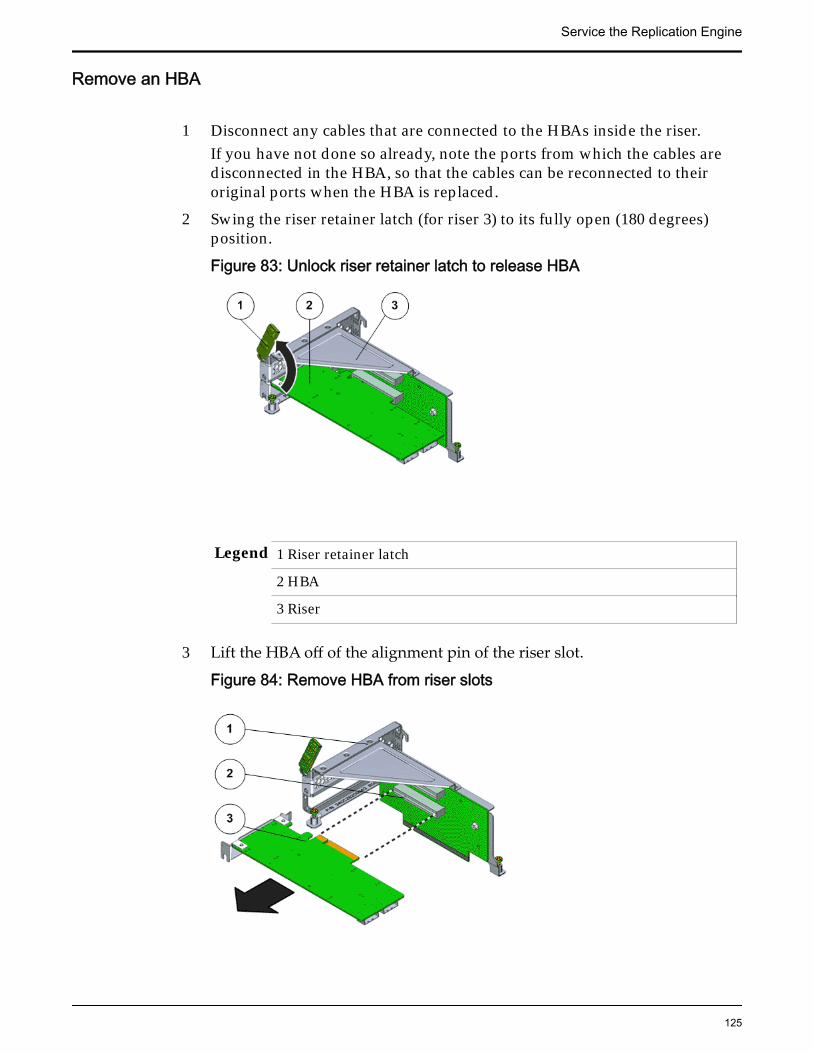
Remove an HBA
1 Disconnect any cables that are connected to the HBAs inside the riser.If you have not done so already, note the ports from which the cables aredisconnected in the HBA, so that the cables can be reconnected to theiroriginal ports when the HBA is replaced.
2 Swing the riser retainer latch (for riser 3) to its fully open (180 degrees)position.
Figure 83: Unlock riser retainer latch to release HBA
Legend 1 Riser retainer latch
2 HBA
3 Riser
3 Lift the HBA off of the alignment pin of the riser slot.
Figure 84: Remove HBA from riser slots
Service the Replication Engine
125

Legend 1 Riser
2 Riser slots
3 HBA
Insert an HBA
1 Unscrew the filler panels on the riser (if any), so that the HBAs can beinserted into the PCIe slots of the replacement riser.
Note: If you are replacing an HBA from the riser with the retainer latch,swing the retainer latch to its fully open (180 degrees) position.
2 Orient the HBA so that the brackets of the HBA align with the alignmentpin in the PCIe slot of the riser.
Important: Hold the HBA by the edges. Do not touch the metal contacts onthe bottom of the card.
3 Push the connectors on the edge of the HBA into the PCIe slot by pushingfirmly to seat the card.
Figure 85: Insert HBA into riser slot
Legend 1 Riser
2 Riser slots
3 HBA
4 Apply firm pressure on each end of the HBA alternately until it clicks intoplace in the riser socket.
Caution: Support the HBA and the riser as necessary to prevent excessiveflexure. Otherwise, the HBA or the riser card might be damaged.
Service the Replication Engine
126

5 When all HBAs have been installed in this riser, swing the retainer latch toits fully closed position. If there is resistance, check the alignment of theHBA and try again.
Figure 86: HBA retainer latch
Legend 1 Riser retainer latch
2 HBA
3 Riser
6 Repeat the procedure for any additional PCIe3 HBAs that might beinstalled in the other risers.
7 Reconnect any cables that had been disconnected from the HBAs.
Note: Make sure that disconnected cables from the HBAs are connected totheir original ports.
Insert a Riser
1 Lower the riser onto the Replication Engine motherboard and press theriser edge connector securely into the socket.
Important: Ensure that any HBAs that must be removed from the failedriser and placed onto the replacement rise are inserted into the same slotson the replacement riser.
Service the Replication Engine
127
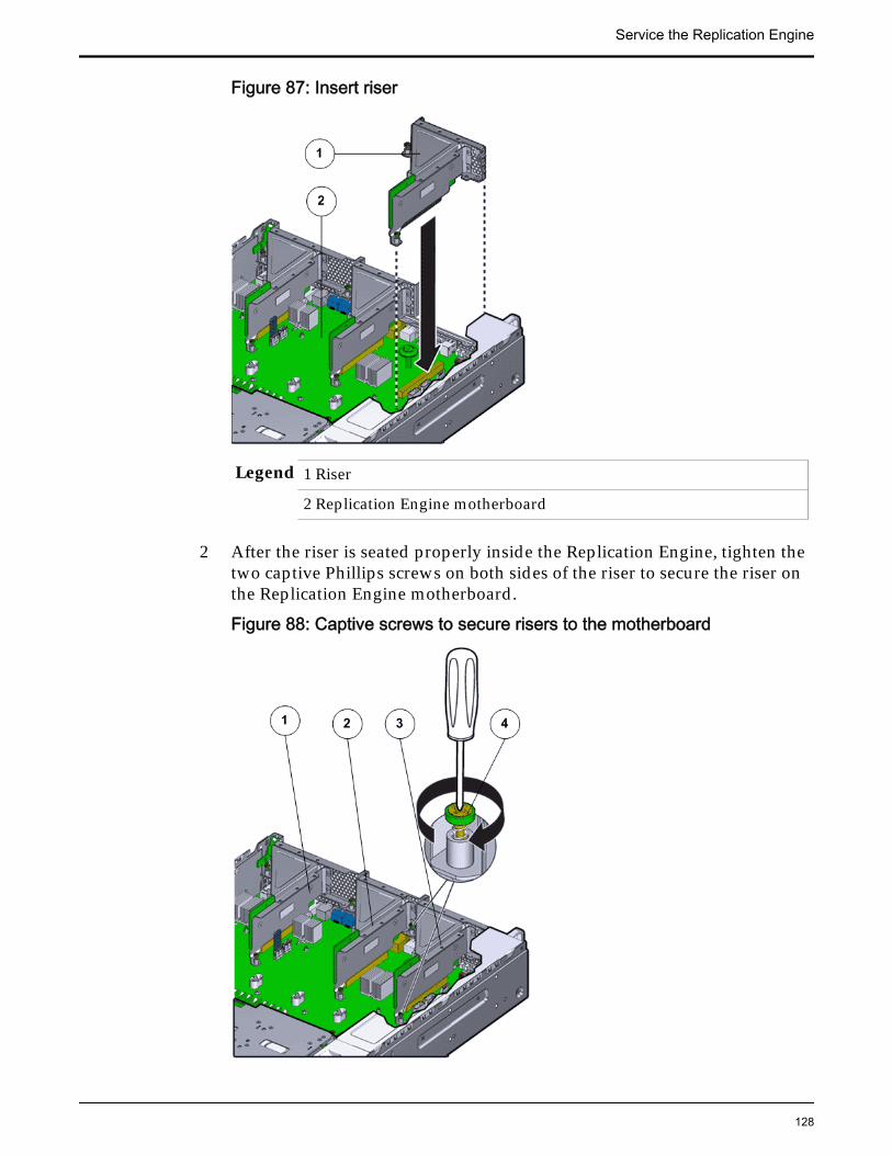
Figure 87: Insert riser
Legend 1 Riser
2 Replication Engine motherboard
2 After the riser is seated properly inside the Replication Engine, tighten thetwo captive Phillips screws on both sides of the riser to secure the riser onthe Replication Engine motherboard.
Figure 88: Captive screws to secure risers to the motherboard
Service the Replication Engine
128
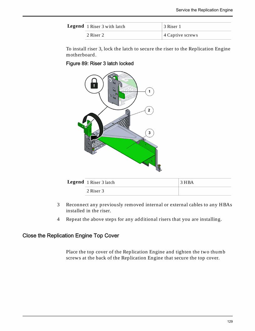
Legend 1 Riser 3 with latch 3 Riser 1
2 Riser 2 4 Captive screws
To install riser 3, lock the latch to secure the riser to the Replication Enginemotherboard.
Figure 89: Riser 3 latch locked
Legend 1 Riser 3 latch 3 HBA
2 Riser 3
3 Reconnect any previously removed internal or external cables to any HBAsinstalled in the riser.
4 Repeat the above steps for any additional risers that you are installing.
Close the Replication Engine Top Cover
Place the top cover of the Replication Engine and tighten the two thumbscrews at the back of the Replication Engine that secure the top cover.
Service the Replication Engine
129

Figure 90: Close Replication Engine top cover
Legend 1 Thumb screws
2 Replication Engine top cover
3 Replication Engine
Reconnect Replication Engine Cabling1 Reconnect all the data cables on the Replication Engine.
Note: Oracle Customer Support recommends labeling all cables connectedto the Replication Engine so that the cables can be reconnected accuratelyto the Replication Engine after the replacement procedure is complete.
2 Reconnect the CMA to the Replication Engine by attaching the release tabon the left and right side of the CMA.
Complete the Component Replacement
1 Slide the Replication Engine back into rack position.
2 Re-connect the cables that were removed from the Replication Engine.
Note: The BIOS is set to automatically power on the Replication Engine,when power is applied.
Service the Replication Engine
130

Replace a Replication Engine DIMMDual in-line memory modules (DIMMs) provide random access memory (RAM)for the central processing units (CPUs) configured in the Replication Engine.DIMMs are connected to the DIMM slots located on both sides of the centralprocessing unit (CPUs) and heat sinks on the Replication Engine motherboard. Afailed DIMM might cause the Replication Engine to be brought offline and mustbe replaced as soon as possible.
Prerequisites: • Ensure that you have a Phillips Number 2screwdriver with at least a 4-inch shaft.
• Before handling a component, touch a groundedsurface to discharge any static electricity.
• Attach an electrostatic discharge (ESD) wrist strap toyour wrist, and stand on an ESD mat while replacingcomponents.
• Ensure that all DIMM slots are filled with either fillerpanels or DIMMs to ensure proper airflow.
Oracle MaxRep Replication Engine has four standard DIMMs
DIMMs are customer replaceable units (CRUs). Replacing a DIMM requires youto bring the Replication Engine offline. The following figure depicts a DIMMmemory module.
Figure 91: DIMM memory module
The following diagram indicates the location of the DIMMs in the DIMM slots.
Service the Replication Engine
131
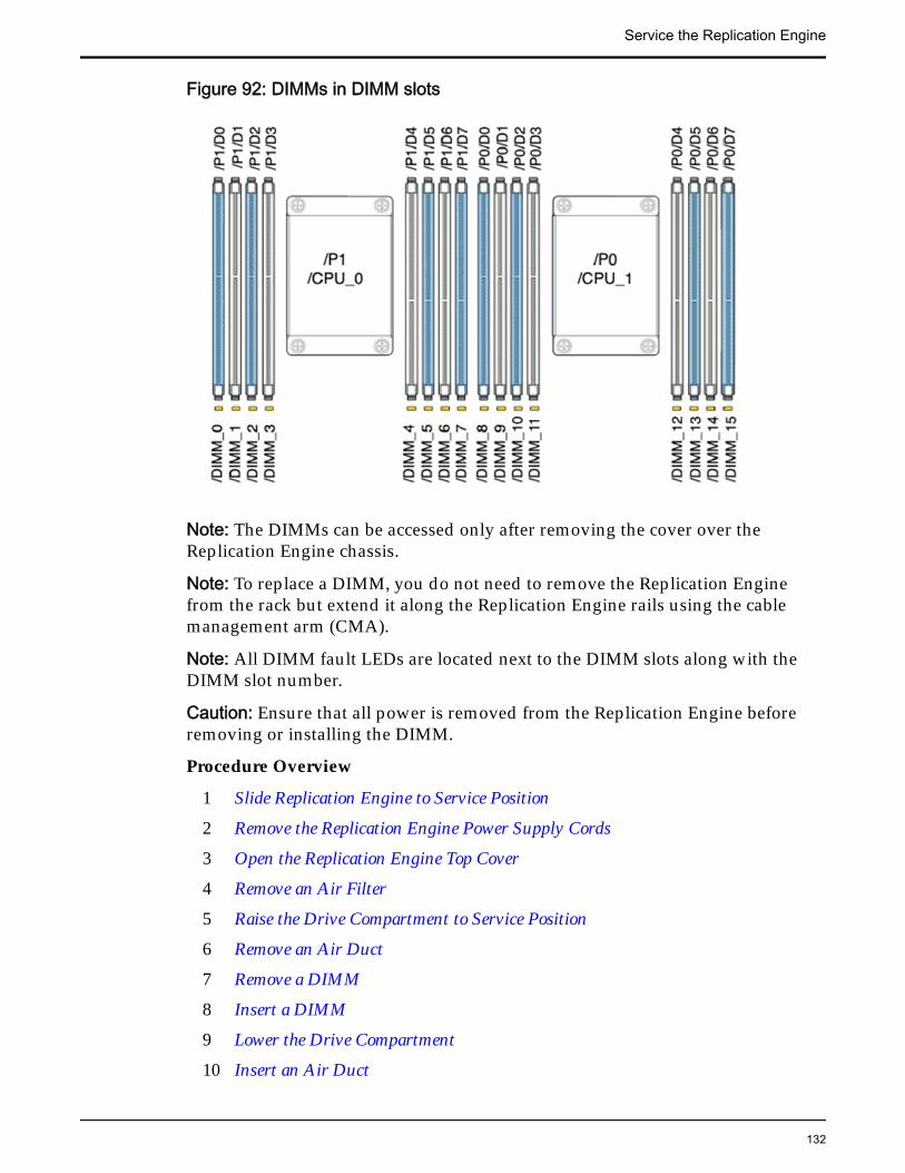
Figure 92: DIMMs in DIMM slots
Note: The DIMMs can be accessed only after removing the cover over theReplication Engine chassis.
Note: To replace a DIMM, you do not need to remove the Replication Enginefrom the rack but extend it along the Replication Engine rails using the cablemanagement arm (CMA).
Note: All DIMM fault LEDs are located next to the DIMM slots along with theDIMM slot number.
Caution: Ensure that all power is removed from the Replication Engine beforeremoving or installing the DIMM.
Procedure Overview
1 Slide Replication Engine to Service Position
2 Remove the Replication Engine Power Supply Cords
3 Open the Replication Engine Top Cover
4 Remove an Air Filter
5 Raise the Drive Compartment to Service Position
6 Remove an Air Duct
7 Remove a DIMM
8 Insert a DIMM
9 Lower the Drive Compartment
10 Insert an Air Duct
Service the Replication Engine
132

11 Insert an Air Filter
12 Close the Replication Engine Top Cover
13 Complete the Component Replacement
Remove the Replication Engine Power Supply Cords
Disconnect the power cords from both power supplies.
Figure 93: Remove power supply cords
Legend 1 Power supply cords
2 Power supply handle
Tip: Always notify affected users that the Replication Engine will bepowered off.
Slide Replication Engine to Service Position
Squeeze the release buttons on either side of the Replication Engine frontpanel at the same time and slide the Replication Engine chassis forwarduntil the slide rails lock into position. You might have to remove screwslocking the front panel to the rack before the Replication Engine slidesforward.
Caution: Deploy any rack anti-tilt mechanism before releasing the releasebuttons and extending the Replication Engine chassis.
Service the Replication Engine
133
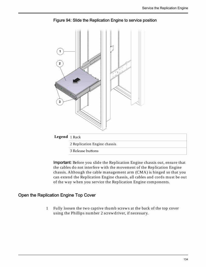
Figure 94: Slide the Replication Engine to service position
Legend 1 Rack
2 Replication Engine chassis
3 Release buttons
Important: Before you slide the Replication Engine chassis out, ensure thatthe cables do not interfere with the movement of the Replication Enginechassis. Although the cable management arm (CMA) is hinged so that youcan extend the Replication Engine chassis, all cables and cords must be outof the way when you service the Replication Engine components.
Open the Replication Engine Top Cover
1 Fully loosen the two captive thumb screws at the back of the top coverusing the Phillips number 2 screwdriver, if necessary.
Service the Replication Engine
134

Figure 95: Captive thumb screws to remove the top cover
Legend 1 Replication Engine top cover
2 Captive screws
2 Slide the top cover backwards 0.5 inches (13 mm) and lift the top coverstraight up and off the Replication Engine chassis.
Remove an Air Filter1 At the front of the Replication Engine chassis, locate the air filter release
tabs.
2 Press the release tabs inwards at the same time to unlock the tabs anddisengage the air filter.
Figure 96: Air filter release tabs
Service the Replication Engine
135

Legend 1 Release tabs 2 Air filter
3 Carefully rotate the top of the air filter outwards and as the release tabsdisengage, lift out the filter.
Figure 97: Remove air filter
4 Set the air filter aside.
Raise the Drive Compartment to Service Position1 Disconnect the cables attached to the backplane.
Cables that must be disconnected include:
• SATA or drive cable
• Motherboard to HDD backplane cable
• USB board cable
Figure 98: Cables connected to the backplane
Service the Replication Engine
136

Legend 1 SATA or drive cable
2 NV-DIMM cables
3 Drive compartment
4 Backplane boards
5 Motherboard to HDD backplane cable
Note: The USB board cable is connected to the Replication Engine displaypanel.
Note: All cables attached to the backplane must be disconnected beforeraising the drive compartment. Otherwise, the cables might get damagedor tear due to unnecessary flexure or pull.
Note: Note the location of all the cable connections to the backplane forlater re-connection of the cables after the replacement procedure iscompleted.
Tip: Refer to the service label for more information on rotating the drivecompartment.
2 Disengage the backplane by loosening the four Phillips Number 2 thumbscrews on the four sides of the backplane using a Phillips Number 2screwdriver and rotate the backplane at a 90 degrees angle.
Figure 99: Disengaging the backplane
Service the Replication Engine
137

Legend 1 Thumb screws that secure the backplane
2 Backplane
Note: Use the screwdriver very carefully to avoid damaging the electricalcircuitry inside the Replication Engine.
3 Raise the backplane and drive compartment to the vertical position.
Figure 100: Drive compartment raised
Legend 1 Backplane
2 Drive compartment
3 Replication Engine motherboard
Remove an Air Duct
1 Remove the air duct by loosening the two brackets and the PhillipsNumber 2 thumb screws on both sides of the air duct.
Service the Replication Engine
138

Figure 101: Remove air duct
Legend 1 Screws that secure air duct
2 Air duct
Note: The brackets that secure the air duct are labeled L (left) and R (right).The left bracket slides forward and the right bracket slides back whenfacing the Replication Engine in the service position.
2 Lift up the air duct from the Replication Engine chassis and set it aside.The following figure shows a Replication Engine air duct:
Figure 102: Air duct
Service the Replication Engine
139

Remove a DIMM
1 Remove the DIMMs by pressing down on the tabs on both sides of theDIMM to unlock it from the slot.
Figure 103: Remove DIMMs
Legend 1 Tabs to release DIMMs
2 DIMM
3 DIMM slot
Note: While inserting or removing DIMMs, ensure that there is nointerference with the cables. Pulling or pressing down on the cables mightcause damage to the cables during the replacement procedure.
2 Lift out the DIMM and set aside on an antistatic mat.
Note: Visually inspect the slots and the memory for physical damage bychecking for cracked or broken plastic in the slot.
Note: Sometimes memory might fault because of dust or improperalignment or damaged slots. Use only compressed air to dust the memory.
Insert a DIMM
Press the DIMM fully into the DIMM slot and ensure that the tabs on bothsides of the DIMM are locked.
Service the Replication Engine
140
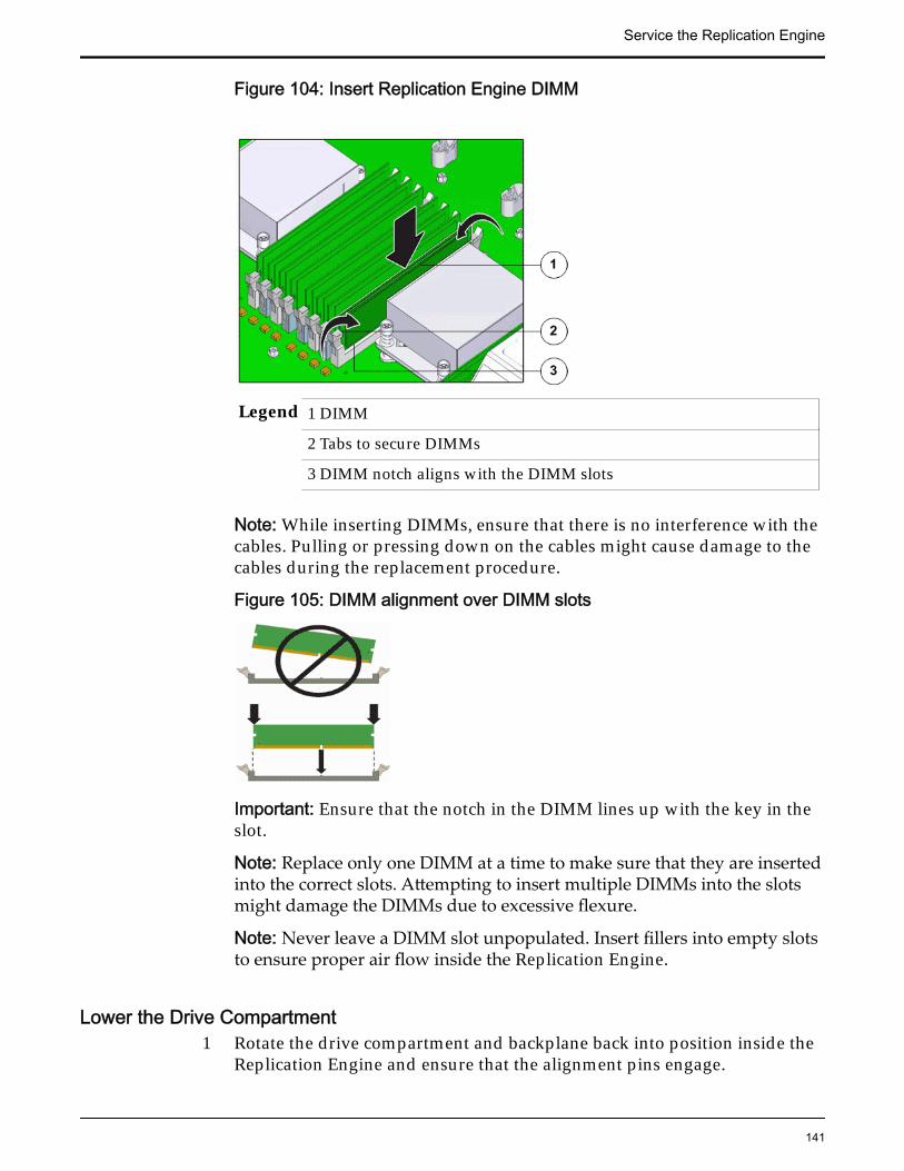
Figure 104: Insert Replication Engine DIMM
Legend 1 DIMM
2 Tabs to secure DIMMs
3 DIMM notch aligns with the DIMM slots
Note: While inserting DIMMs, ensure that there is no interference with thecables. Pulling or pressing down on the cables might cause damage to thecables during the replacement procedure.
Figure 105: DIMM alignment over DIMM slots
Important: Ensure that the notch in the DIMM lines up with the key in theslot.
Note: Replace only one DIMM at a time to make sure that they are insertedinto the correct slots. Attempting to insert multiple DIMMs into the slotsmight damage the DIMMs due to excessive flexure.
Note: Never leave a DIMM slot unpopulated. Insert fillers into empty slotsto ensure proper air flow inside the Replication Engine.
Lower the Drive Compartment1 Rotate the drive compartment and backplane back into position inside the
Replication Engine and ensure that the alignment pins engage.
Service the Replication Engine
141

Note: To confirm that the backplane is locked into position, listen for anaudible click or feel the backplane engage with the Replication Engine.
2 Secure the backplane inside the Replication Engine by inserting the fourPhillips Number 2 thumb screws on the four sides of the backplane andtightening them using a Phillips Number 2 screwdriver.
3 Reconnect all the cables that had been previously disconnected from thebackplane.Cables that must be reconnected include:
• SATA or drive cable
• Motherboard to HDD backplane cable
Figure 106: Reconnect cables to the backplane
Legend 1 SATA or drive cable
2 NV-DIMM cable
3 Drive compartment
4 Backplane boards
5 Motherboard to HDD backplane cable
Insert an Air Duct
Secure the air duct inside the Replication Engine by tightening the twoPhillips Number 2 screws into position.
Note: The brackets that secure the air duct are labeled L (left) and R (right).The left bracket slides forward, the right bracket slides back when facingthe Replication Engine in the service position.
Service the Replication Engine
142

Insert an Air Filter1 Tilt the top of the air filter slightly towards you and insert the bottom two
hooks into the mounting tabs.
Figure 107: Insert air filter
Important: Ensure that nothing interferes with the edges of the air filter andthat the air filter seats properly.
2 Press the top corners of the air filter to engage the top two air filter hookswith the top rail tabs.
3 Press both air filter release tabs until they lock in place.
Close the Replication Engine Top Cover
Place the top cover of the Replication Engine and tighten the two thumbscrews at the back of the Replication Engine that secure the top cover.
Service the Replication Engine
143

Figure 108: Close Replication Engine top cover
Legend 1 Thumb screws
2 Replication Engine top cover
3 Replication Engine
Complete the Component Replacement
1 Slide the Replication Engine back into rack position.
2 Re-connect the cables that were removed from the Replication Engine.
Note: The BIOS is set to automatically power on the Replication Engine,when power is applied.
Replace a Replication Engine Disk BackplaneThe disk backplane provides a physical interconnect for the drives. The diskbackplane, if damaged, prevents the drives from seating properly. Improperseating prevents the modules from providing backup power to flash memory,which can lead to data loss.
Prerequisites: • Ensure that you have a Phillips Number 2screwdriver with at least a 4-inch shaft.
• Before handling a component, touch a groundedsurface to discharge any static electricity.
Service the Replication Engine
144
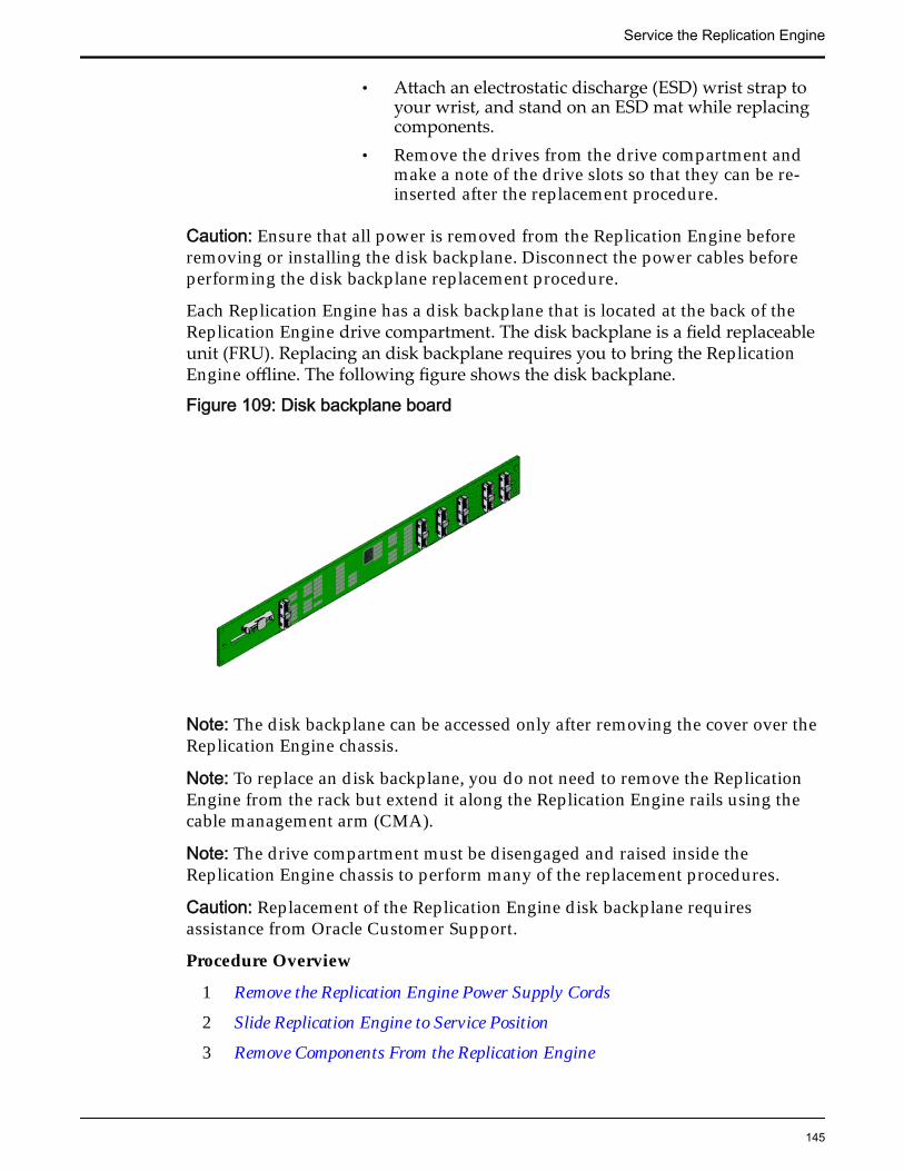
• Attach an electrostatic discharge (ESD) wrist strap toyour wrist, and stand on an ESD mat while replacingcomponents.
• Remove the drives from the drive compartment andmake a note of the drive slots so that they can be re-inserted after the replacement procedure.
Caution: Ensure that all power is removed from the Replication Engine beforeremoving or installing the disk backplane. Disconnect the power cables beforeperforming the disk backplane replacement procedure.
Each Replication Engine has a disk backplane that is located at the back of theReplication Engine drive compartment. The disk backplane is a field replaceableunit (FRU). Replacing an disk backplane requires you to bring the ReplicationEngine offline. The following figure shows the disk backplane.
Figure 109: Disk backplane board
Note: The disk backplane can be accessed only after removing the cover over theReplication Engine chassis.
Note: To replace an disk backplane, you do not need to remove the ReplicationEngine from the rack but extend it along the Replication Engine rails using thecable management arm (CMA).
Note: The drive compartment must be disengaged and raised inside theReplication Engine chassis to perform many of the replacement procedures.
Caution: Replacement of the Replication Engine disk backplane requiresassistance from Oracle Customer Support.
Procedure Overview
1 Remove the Replication Engine Power Supply Cords
2 Slide Replication Engine to Service Position
3 Remove Components From the Replication Engine
Service the Replication Engine
145
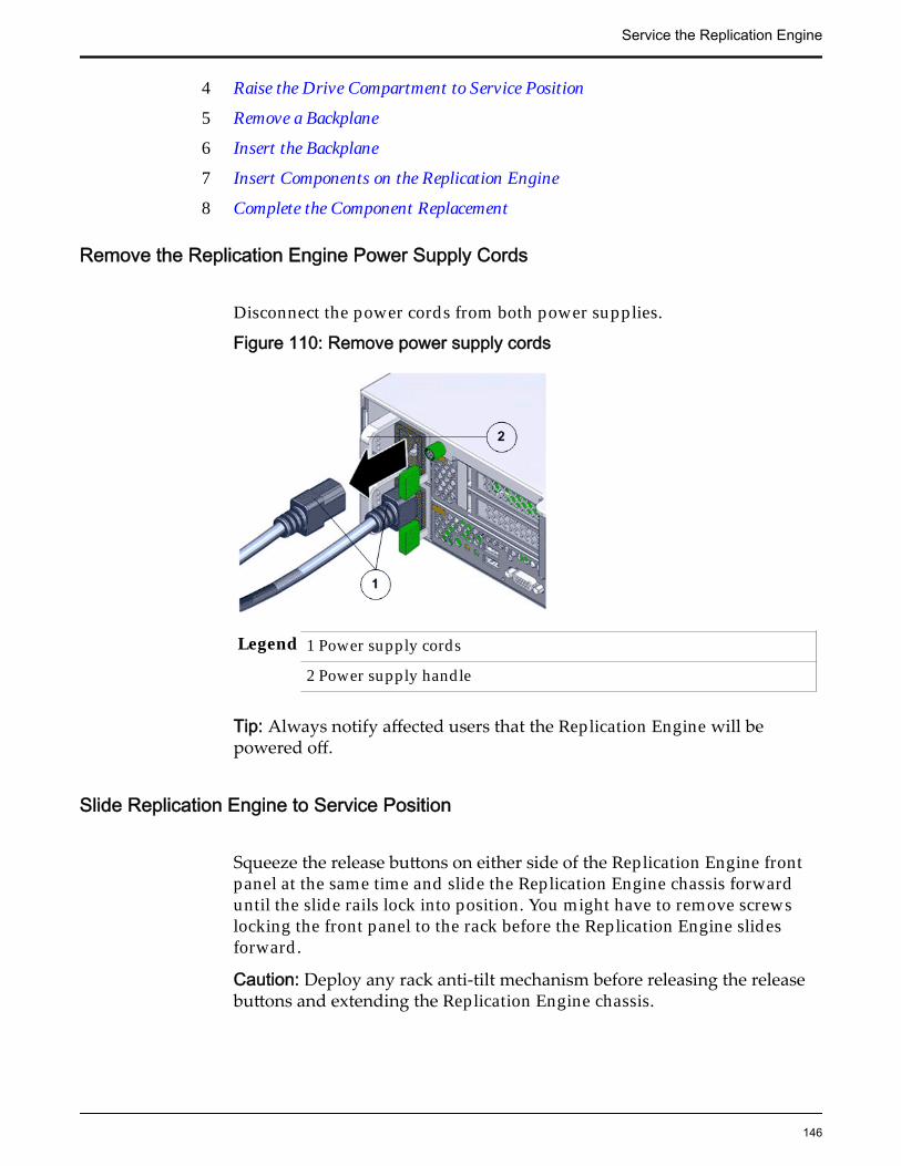
4 Raise the Drive Compartment to Service Position
5 Remove a Backplane
6 Insert the Backplane
7 Insert Components on the Replication Engine
8 Complete the Component Replacement
Remove the Replication Engine Power Supply Cords
Disconnect the power cords from both power supplies.
Figure 110: Remove power supply cords
Legend 1 Power supply cords
2 Power supply handle
Tip: Always notify affected users that the Replication Engine will bepowered off.
Slide Replication Engine to Service Position
Squeeze the release buttons on either side of the Replication Engine frontpanel at the same time and slide the Replication Engine chassis forwarduntil the slide rails lock into position. You might have to remove screwslocking the front panel to the rack before the Replication Engine slidesforward.
Caution: Deploy any rack anti-tilt mechanism before releasing the releasebuttons and extending the Replication Engine chassis.
Service the Replication Engine
146

Figure 111: Slide the Replication Engine to service position
Legend 1 Rack
2 Replication Engine chassis
3 Release buttons
Important: Before you slide the Replication Engine chassis out, ensure thatthe cables do not interfere with the movement of the Replication Enginechassis. Although the cable management arm (CMA) is hinged so that youcan extend the Replication Engine chassis, all cables and cords must be outof the way when you service the Replication Engine components.
Remove Components From the Replication Engine
Note: Some components must be removed from the Replication Engine as aprerequisite for access while replacing the failed component.
Note: All components that are removed from the Replication Engine must beplaced on an antistatic surface or ESD qualified mat.
Remove an Air Filter
Service the Replication Engine
147

1 At the front of the Replication Engine chassis, locate the air filter releasetabs.
2 Press the release tabs inwards at the same time to unlock the tabs anddisengage the air filter.
Figure 112: Air filter release tabs
Legend 1 Release tabs 2 Air filter
3 Carefully rotate the top of the air filter outwards and as the release tabsdisengage, lift out the filter.
Figure 113: Remove air filter
4 Set the air filter aside.
Service the Replication Engine
148

Open the Replication Engine Top Cover
1 Fully loosen the two captive thumb screws at the back of the top coverusing the Phillips number 2 screwdriver, if necessary.
Figure 114: Captive thumb screws to remove the top cover
Legend 1 Replication Engine top cover
2 Captive screws
2 Slide the top cover backwards 0.5 inches (13 mm) and lift the top coverstraight up and off the Replication Engine chassis.
Remove a Replication Engine Drive1 Remove the Replication Engine drive from the drive compartment by
pushing the latch release button to open the latch.
Service the Replication Engine
149

Figure 115: Open drive latch
Legend 1 Drive 2 Latch release button
3 Replication Engine front
Important: Do not bend the latch too far to the right. Bending the latch candamage the latch.
Important: For drives that are removed but will be later reinserted, label thedrive with the position that the drive occupies in the Replication Engine.Reinserting drives in the incorrect slot might result in data loss and a fullrecovery might be required to resume operation.
2 Grasp the latch and pull the drive out of the Replication Engine drivecompartment.
Figure 116: Remove drive
Legend 1 Drive 2 Replication Engine drive compartment
3 Replication Engine front
Service the Replication Engine
150
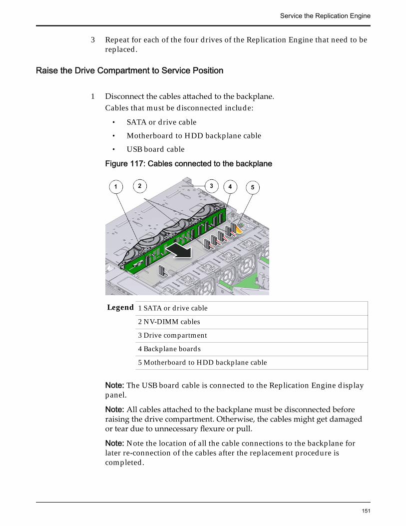
3 Repeat for each of the four drives of the Replication Engine that need to bereplaced.
Raise the Drive Compartment to Service Position
1 Disconnect the cables attached to the backplane.Cables that must be disconnected include:
• SATA or drive cable
• Motherboard to HDD backplane cable
• USB board cable
Figure 117: Cables connected to the backplane
Legend 1 SATA or drive cable
2 NV-DIMM cables
3 Drive compartment
4 Backplane boards
5 Motherboard to HDD backplane cable
Note: The USB board cable is connected to the Replication Engine displaypanel.
Note: All cables attached to the backplane must be disconnected beforeraising the drive compartment. Otherwise, the cables might get damagedor tear due to unnecessary flexure or pull.
Note: Note the location of all the cable connections to the backplane forlater re-connection of the cables after the replacement procedure iscompleted.
Service the Replication Engine
151
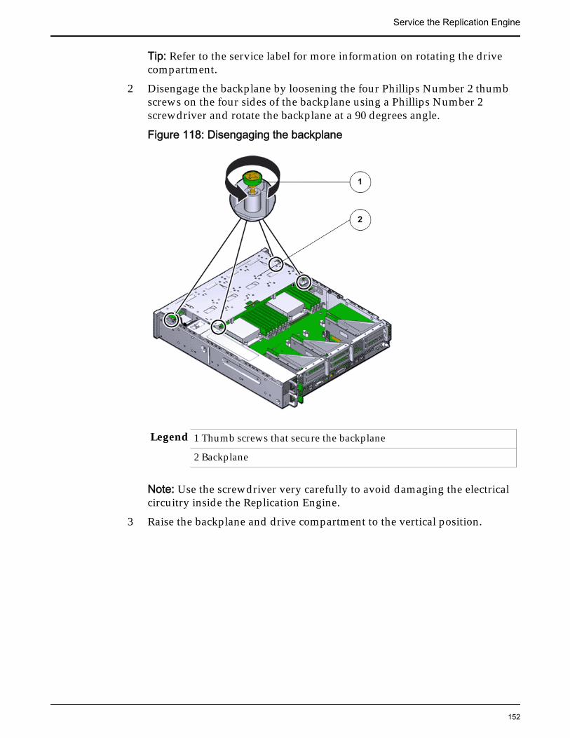
Tip: Refer to the service label for more information on rotating the drivecompartment.
2 Disengage the backplane by loosening the four Phillips Number 2 thumbscrews on the four sides of the backplane using a Phillips Number 2screwdriver and rotate the backplane at a 90 degrees angle.
Figure 118: Disengaging the backplane
Legend 1 Thumb screws that secure the backplane
2 Backplane
Note: Use the screwdriver very carefully to avoid damaging the electricalcircuitry inside the Replication Engine.
3 Raise the backplane and drive compartment to the vertical position.
Service the Replication Engine
152

Figure 119: Drive compartment raised
Legend 1 Backplane
2 Drive compartment
3 Replication Engine motherboard
Remove a Backplane
1 Remove the five screws that secure the backplane boards to the drivecompartment.
Service the Replication Engine
153

Figure 120: Unscrew the backplane boards
Legend 1 Screws securing the backplane boards
2 Backplane board
3 Drive compartment
2 Lift the backplane board off of the alignment pins and out of theReplication Engine chassis.
Service the Replication Engine
154

Figure 121: Remove the backplane boards
Legend 1 Drive compartment
2 Backplane boards
3 Place the backplane on an antistatic mat.
Insert the Backplane
1 Position the backplane boards to where it will install into the ReplicationEngine chassis.
Service the Replication Engine
155

Figure 122: Backplane boards
Legend 1 Drive compartment 2 Backplane boards
Note: The backplane boards align with the drive connectors. In thefollowing diagram, the two alignment holes are on the left and the singlealignment hole is on the right.
2 Install and tighten the five screws that secure the backplane boards ontothe drive compartment.
Service the Replication Engine
156

Figure 123: Backplane boards secured
Legend 1 Screws securing the backplane boards 2 Backplane board
3 Drive compartment
3 Secure the backplane inside the Replication Engine by inserting the fourPhillips Number 2 thumb screws on the four sides of the backplane andtightening them using a Phillips Number 2 screwdriver.
4 Rotate the drive compartment and backplane back into position inside theReplication Engine and ensure that the alignment pins engage.
Note: To confirm that the backplane is locked into position, listen for anaudible click or feel the backplane engage with the Replication Engine.
5 Reconnect all the cables that had been previously disconnected from thebackplane.Cables that must be reconnected include:
• SATA or drive cable
• Motherboard to HDD backplane cable
Service the Replication Engine
157
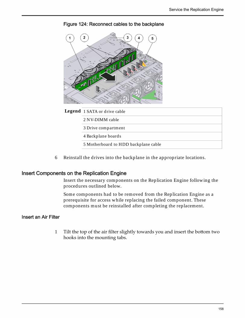
Figure 124: Reconnect cables to the backplane
Legend 1 SATA or drive cable
2 NV-DIMM cable
3 Drive compartment
4 Backplane boards
5 Motherboard to HDD backplane cable
6 Reinstall the drives into the backplane in the appropriate locations.
Insert Components on the Replication EngineInsert the necessary components on the Replication Engine following theprocedures outlined below.
Some components had to be removed from the Replication Engine as aprerequisite for access while replacing the failed component. Thesecomponents must be reinstalled after completing the replacement.
Insert an Air Filter
1 Tilt the top of the air filter slightly towards you and insert the bottom twohooks into the mounting tabs.
Service the Replication Engine
158

Figure 125: Insert air filter
Important: Ensure that nothing interferes with the edges of the air filter andthat the air filter seats properly.
2 Press the top corners of the air filter to engage the top two air filter hookswith the top rail tabs.
3 Press both air filter release tabs until they lock in place.
Close the Replication Engine Top Cover
Place the top cover of the Replication Engine and tighten the two thumbscrews at the back of the Replication Engine that secure the top cover.
Service the Replication Engine
159

Figure 126: Close Replication Engine top cover
Legend 1 Thumb screws
2 Replication Engine top cover
3 Replication Engine
Complete the Component Replacement
1 Slide the Replication Engine back into rack position.
2 Re-connect the cables that were removed from the Replication Engine.
Note: The BIOS is set to automatically power on the Replication Engine,when power is applied.
Replace a Replication Engine Heat SinkThe heat sink serves as a cooling device to prevent the CPU in the ReplicationEngine from overheating. A damaged heat sink can cause the Replication EngineCPU to overheat, which would cause the CPU to fail. You must replace adamaged heat sink as soon as possible.
Caution: Ensure that all power is removed from the Replication Engine beforereplacing the heat sink. Disconnect the power cables before performing the heatsink replacement procedure.
Service the Replication Engine
160

Prerequisites: • Ensure that you have a Phillips Number 2screwdriver with at least a 4-inch shaft.
• Before handling a component, touch a groundedsurface to discharge any static electricity.
• Attach an electrostatic discharge (ESD) wrist strap toyour wrist, and stand on an ESD mat while replacingcomponents.
Each Replication Engine has two heat sinks located above the CPUs on theReplication Engine motherboard. Heat sinks are usually durable and need not bereplaced. Heat sinks are field replaceable units (FRUs). Replacing a heat sinkrequires you to bring the Replication Engine offline. The following figuredisplays the Replication Engine heat sink.
Figure 127: Heat sink
Note: The heat sinks can be accessed only after removing the cover over theReplication Engine chassis.
Note: To replace a heat sink, you do not need to remove the Replication Enginefrom the rack but extend it along the Replication Engine rails.
Procedure Overview
1 Slide Replication Engine to Service Position
2 Remove the Replication Engine Power Supply Cords
3 Open the Replication Engine Top Cover
4 Remove an Air Duct
5 Raise the Drive Compartment to Service Position
6 Remove a Heat Sink
7 Insert a Heat Sink
8 Insert an Air Duct
Service the Replication Engine
161

9 Close the Replication Engine Top Cover
10 Lower the Drive Compartment
11 Complete the Component Replacement
Remove the Replication Engine Power Supply Cords
Disconnect the power cords from both power supplies.
Figure 128: Remove power supply cords
Legend 1 Power supply cords
2 Power supply handle
Tip: Always notify affected users that the Replication Engine will bepowered off.
Slide Replication Engine to Service Position
Squeeze the release buttons on either side of the Replication Engine frontpanel at the same time and slide the Replication Engine chassis forwarduntil the slide rails lock into position. You might have to remove screwslocking the front panel to the rack before the Replication Engine slidesforward.
Caution: Deploy any rack anti-tilt mechanism before releasing the releasebuttons and extending the Replication Engine chassis.
Service the Replication Engine
162

Figure 129: Slide the Replication Engine to service position
Legend 1 Rack
2 Replication Engine chassis
3 Release buttons
Important: Before you slide the Replication Engine chassis out, ensure thatthe cables do not interfere with the movement of the Replication Enginechassis. Although the cable management arm (CMA) is hinged so that youcan extend the Replication Engine chassis, all cables and cords must be outof the way when you service the Replication Engine components.
Open the Replication Engine Top Cover
1 Fully loosen the two captive thumb screws at the back of the top coverusing the Phillips number 2 screwdriver, if necessary.
Service the Replication Engine
163

Figure 130: Captive thumb screws to remove the top cover
Legend 1 Replication Engine top cover
2 Captive screws
2 Slide the top cover backwards 0.5 inches (13 mm) and lift the top coverstraight up and off the Replication Engine chassis.
Remove an Air Duct
1 Remove the air duct by loosening the two brackets and the PhillipsNumber 2 thumb screws on both sides of the air duct.
Service the Replication Engine
164

Figure 131: Remove air duct
Legend 1 Screws that secure air duct
2 Air duct
Note: The brackets that secure the air duct are labeled L (left) and R (right).The left bracket slides forward and the right bracket slides back whenfacing the Replication Engine in the service position.
2 Lift up the air duct from the Replication Engine chassis and set it aside.The following figure shows a Replication Engine air duct:
Figure 132: Air duct
Service the Replication Engine
165
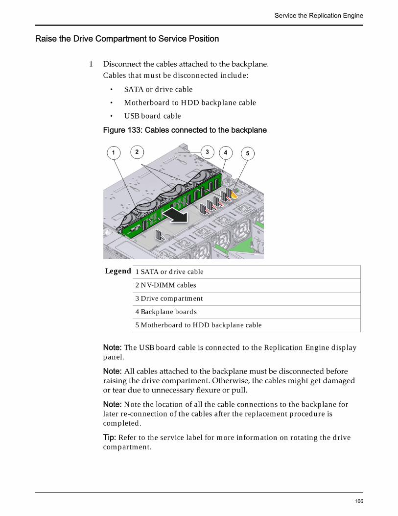
Raise the Drive Compartment to Service Position
1 Disconnect the cables attached to the backplane.Cables that must be disconnected include:
• SATA or drive cable
• Motherboard to HDD backplane cable
• USB board cable
Figure 133: Cables connected to the backplane
Legend 1 SATA or drive cable
2 NV-DIMM cables
3 Drive compartment
4 Backplane boards
5 Motherboard to HDD backplane cable
Note: The USB board cable is connected to the Replication Engine displaypanel.
Note: All cables attached to the backplane must be disconnected beforeraising the drive compartment. Otherwise, the cables might get damagedor tear due to unnecessary flexure or pull.
Note: Note the location of all the cable connections to the backplane forlater re-connection of the cables after the replacement procedure iscompleted.
Tip: Refer to the service label for more information on rotating the drivecompartment.
Service the Replication Engine
166

2 Disengage the backplane by loosening the four Phillips Number 2 thumbscrews on the four sides of the backplane using a Phillips Number 2screwdriver and rotate the backplane at a 90 degrees angle.
Figure 134: Disengaging the backplane
Legend 1 Thumb screws that secure the backplane
2 Backplane
Note: Use the screwdriver very carefully to avoid damaging the electricalcircuitry inside the Replication Engine.
3 Raise the backplane and drive compartment to the vertical position.
Service the Replication Engine
167

Figure 135: Drive compartment raised
Legend 1 Backplane
2 Drive compartment
3 Replication Engine motherboard
Remove a Heat Sink
1 Remove the access window on the air duct to remove the heat sink andCPU.
2 Loosen the four Phillips screws on the four sides of the heat sink thatsecure the heat sink to the Replication Engine chassis a few turns at a timein a diametrically opposed pattern using a Phillips Number 2 screwdriver.
Figure 136: Loosen four screws to remove heat sink
Legend 1 Heat sink 2 Phillips screws that secure the heat sink
Note: Loosen one screw, then loosen the screw opposite that screw on theheat sink to prevent it from warping the motherboard on which it ismounted.
Service the Replication Engine
168

3 Gently twist the heat sink left and right, while pulling upward, to separatethe heat sink from the top of the CPU.
Note: A thin layer of thermal grease separates the heat sink and the CPU.This thermal grease also acts as an adhesive.
Caution: Do not allow the thermal grease to contaminate the work space orother components.
4 Lift up the failed heat sink and set aside on an antistatic mat.
5 Visually inspect the failed heat sink to verify if the thermal grease hasdried out and use an alcohol pad to clean the thermal grease from theunderside of the heat sink.
Note: Be careful not to get the thermal grease on your fingers, as this couldresult in contamination of components.
Caution: Failure to clean the heat sink before removing the CPU can resultin the accidental contamination of the CPU socket or other components.
Insert a Heat Sink
1 Secure the heat sink over the CPU to the Replication Engine motherboardby inserting the four screws on the four sides of the heat sink.
Note: Ensure that the CPU is cleaned with an alcohol pad and freshthermal grease is applied, when installing a new heat sink, to preventoverheating and damage to the CPU.
Important: Ensure that the heat sink and the screws are aligned correctlyand the screws on diagonal ends of the heat sink are tightened first. Aslight force might need to be applied to push down the screwdriver whiletightening the screws to overcome the tension generated.
2 Tighten the four Phillips screws on the heat sink a few turns at a time in adiametrically opposed pattern using a Phillips Number 2 screwdriver.
Figure 137: Insert heat sink
Service the Replication Engine
169

Legend 1 Heat sink
2 Phillips screws that secure the heat sink
Insert an Air Duct
Secure the air duct inside the Replication Engine by tightening the twoPhillips Number 2 screws into position.
Note: The brackets that secure the air duct are labeled L (left) and R (right).The left bracket slides forward, the right bracket slides back when facingthe Replication Engine in the service position.
Lower the Drive Compartment
1 Rotate the drive compartment and backplane back into position inside theReplication Engine and ensure that the alignment pins engage.
Note: To confirm that the backplane is locked into position, listen for anaudible click or feel the backplane engage with the Replication Engine.
2 Secure the backplane inside the Replication Engine by inserting the fourPhillips Number 2 thumb screws on the four sides of the backplane andtightening them using a Phillips Number 2 screwdriver.
3 Reconnect all the cables that had been previously disconnected from thebackplane.Cables that must be reconnected include:
• SATA or drive cable
• Motherboard to HDD backplane cable
Figure 138: Reconnect cables to the backplane
Service the Replication Engine
170

Legend 1 SATA or drive cable
2 NV-DIMM cable
3 Drive compartment
4 Backplane boards
5 Motherboard to HDD backplane cable
Close the Replication Engine Top Cover
Place the top cover of the Replication Engine and tighten the two thumbscrews at the back of the Replication Engine that secure the top cover.
Figure 139: Close Replication Engine top cover
Legend 1 Thumb screws
2 Replication Engine top cover
3 Replication Engine
Complete the Component Replacement
1 Slide the Replication Engine back into rack position.
2 Re-connect the cables that were removed from the Replication Engine.
Service the Replication Engine
171

Note: The BIOS is set to automatically power on the Replication Engine,when power is applied.
Replace a Replication Engine CPUThe CPU provides data computing and processing power to the ReplicationEngine. A failed CPU might impact the processing power of the ReplicationEngine and must be replaced as soon as possible.
Caution: Ensure that all power is removed from the Replication Engine beforereplacing the CPU. Disconnect the power cables before performing the CPUreplacement procedure.
Prerequisites: • Ensure that you have a Phillips Number 2screwdriver with at least a 4-inch shaft.
• Before handling a component, touch a groundedsurface to discharge any static electricity.
• Attach an electrostatic discharge (ESD) wrist strap toyour wrist, and stand on an ESD mat while replacingcomponents.
• Ensure that you have the thermal grease and syringeavailable to clean the CPU.
Each Replication Engine has two CPUs located under the two heat sinks insidethe chassis. A CPU is a small square component that contains multiple pins orconnectors on the underside and is inserted pin side down into the CPU socketlocated in the motherboard. The CPU is a field replaceable unit (FRU). Replacinga CPU requires you to power off the Replication Engine. The following figureshows the location of the CPU on the Replication Engine motherboard.
Service the Replication Engine
172

Figure 140: CPU location
Legend 1 Heat sink
2 CPU socket
3 CPU
4 CPU socket levers
The following figure shows a Replication Engine CPU.
Figure 141: CPU
Caution: Replacement of the Replication Engine CPU requires assistance fromOracle Customer Support.
Note: The CPUs can be accessed only after removing the cover over theReplication Engine chassis.
Note: To replace a CPU, you do not need to remove the Replication Engine fromthe rack but extend it along the Replication Engine rails.
Service the Replication Engine
173

Procedure Overview
1 Slide Replication Engine to Service Position
2 Remove the Replication Engine Power Supply Cords
3 Open the Replication Engine Top Cover
4 Remove an Air Duct
5 Raise the Drive Compartment to Service Position
6 Remove a Heat Sink
7 Remove a CPU
8 Insert a CPU
9 Insert a Heat Sink
10 Close the Replication Engine Top Cover
11 Lower the Drive Compartment
12 Complete the Component Replacement
Remove the Replication Engine Power Supply Cords
Disconnect the power cords from both power supplies.
Figure 142: Remove power supply cords
Legend 1 Power supply cords
2 Power supply handle
Tip: Always notify affected users that the Replication Engine will bepowered off.
Slide Replication Engine to Service Position
Service the Replication Engine
174
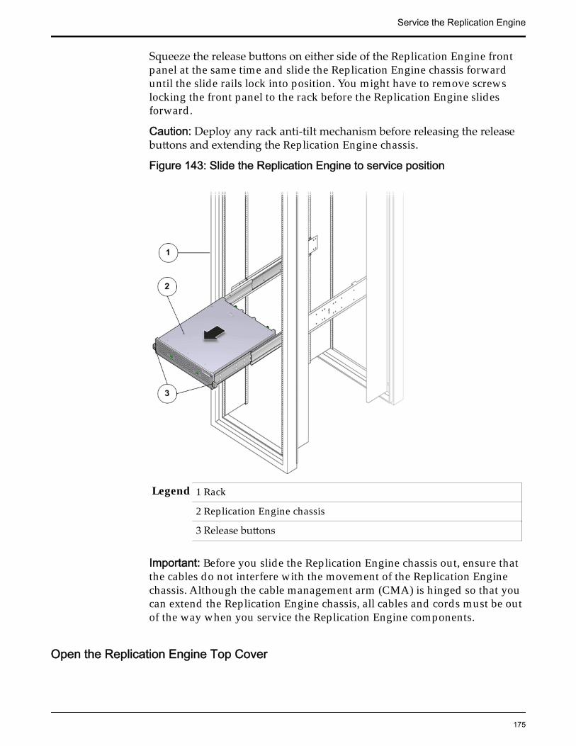
Squeeze the release buttons on either side of the Replication Engine frontpanel at the same time and slide the Replication Engine chassis forwarduntil the slide rails lock into position. You might have to remove screwslocking the front panel to the rack before the Replication Engine slidesforward.
Caution: Deploy any rack anti-tilt mechanism before releasing the releasebuttons and extending the Replication Engine chassis.
Figure 143: Slide the Replication Engine to service position
Legend 1 Rack
2 Replication Engine chassis
3 Release buttons
Important: Before you slide the Replication Engine chassis out, ensure thatthe cables do not interfere with the movement of the Replication Enginechassis. Although the cable management arm (CMA) is hinged so that youcan extend the Replication Engine chassis, all cables and cords must be outof the way when you service the Replication Engine components.
Open the Replication Engine Top Cover
Service the Replication Engine
175
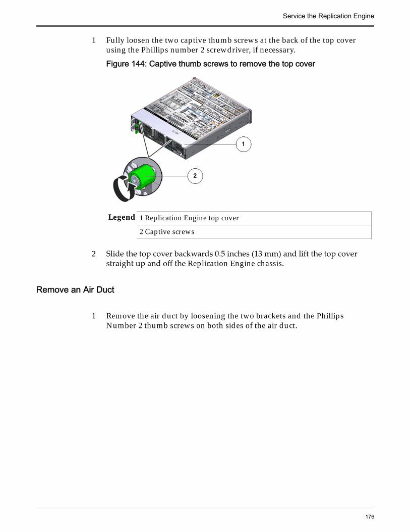
1 Fully loosen the two captive thumb screws at the back of the top coverusing the Phillips number 2 screwdriver, if necessary.
Figure 144: Captive thumb screws to remove the top cover
Legend 1 Replication Engine top cover
2 Captive screws
2 Slide the top cover backwards 0.5 inches (13 mm) and lift the top coverstraight up and off the Replication Engine chassis.
Remove an Air Duct
1 Remove the air duct by loosening the two brackets and the PhillipsNumber 2 thumb screws on both sides of the air duct.
Service the Replication Engine
176
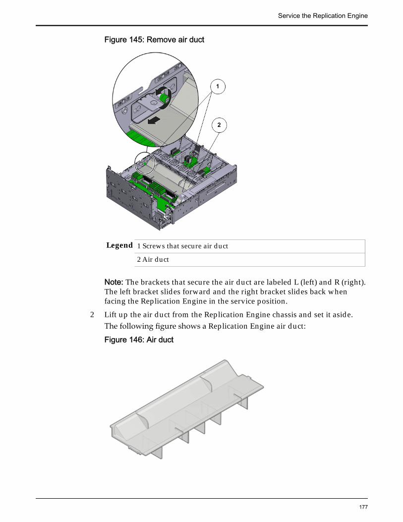
Figure 145: Remove air duct
Legend 1 Screws that secure air duct
2 Air duct
Note: The brackets that secure the air duct are labeled L (left) and R (right).The left bracket slides forward and the right bracket slides back whenfacing the Replication Engine in the service position.
2 Lift up the air duct from the Replication Engine chassis and set it aside.The following figure shows a Replication Engine air duct:
Figure 146: Air duct
Service the Replication Engine
177

Raise the Drive Compartment to Service Position
1 Disconnect the cables attached to the backplane.Cables that must be disconnected include:
• SATA or drive cable
• Motherboard to HDD backplane cable
• USB board cable
Figure 147: Cables connected to the backplane
Legend 1 SATA or drive cable
2 NV-DIMM cables
3 Drive compartment
4 Backplane boards
5 Motherboard to HDD backplane cable
Note: The USB board cable is connected to the Replication Engine displaypanel.
Note: All cables attached to the backplane must be disconnected beforeraising the drive compartment. Otherwise, the cables might get damagedor tear due to unnecessary flexure or pull.
Note: Note the location of all the cable connections to the backplane forlater re-connection of the cables after the replacement procedure iscompleted.
Tip: Refer to the service label for more information on rotating the drivecompartment.
Service the Replication Engine
178
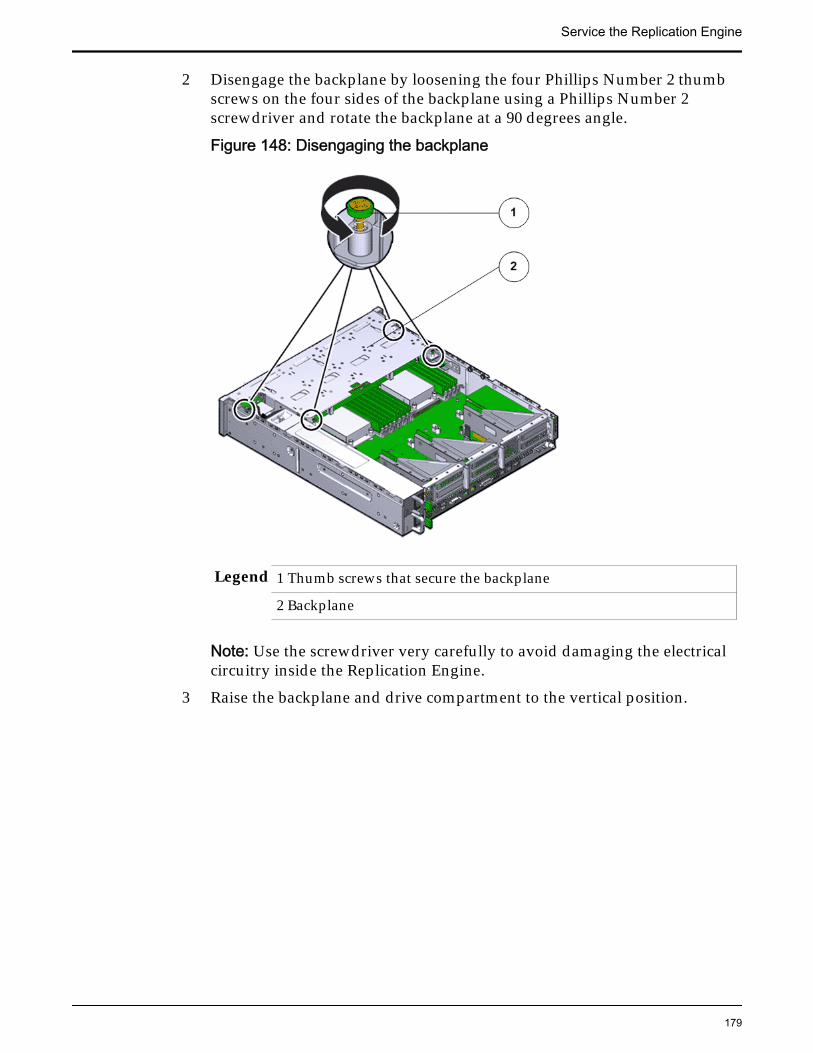
2 Disengage the backplane by loosening the four Phillips Number 2 thumbscrews on the four sides of the backplane using a Phillips Number 2screwdriver and rotate the backplane at a 90 degrees angle.
Figure 148: Disengaging the backplane
Legend 1 Thumb screws that secure the backplane
2 Backplane
Note: Use the screwdriver very carefully to avoid damaging the electricalcircuitry inside the Replication Engine.
3 Raise the backplane and drive compartment to the vertical position.
Service the Replication Engine
179

Figure 149: Drive compartment raised
Legend 1 Backplane
2 Drive compartment
3 Replication Engine motherboard
Remove a Heat Sink
1 Remove the access window on the air duct to remove the heat sink andCPU.
2 Loosen the four Phillips screws on the four sides of the heat sink thatsecure the heat sink to the Replication Engine chassis a few turns at a timein a diametrically opposed pattern using a Phillips Number 2 screwdriver.
Figure 150: Loosen four screws to remove heat sink
Legend 1 Heat sink 2 Phillips screws that secure the heat sink
Note: Loosen one screw, then loosen the screw opposite that screw on theheat sink to prevent it from warping the motherboard on which it ismounted.
Service the Replication Engine
180

3 Gently twist the heat sink left and right, while pulling upward, to separatethe heat sink from the top of the CPU.
Note: A thin layer of thermal grease separates the heat sink and the CPU.This thermal grease also acts as an adhesive.
Caution: Do not allow the thermal grease to contaminate the work space orother components.
4 Lift up the failed heat sink and set aside on an antistatic mat.
5 Visually inspect the failed heat sink to verify if the thermal grease hasdried out and use an alcohol pad to clean the thermal grease from theunderside of the heat sink.
Note: Be careful not to get the thermal grease on your fingers, as this couldresult in contamination of components.
Caution: Failure to clean the heat sink before removing the CPU can resultin the accidental contamination of the CPU socket or other components.
Remove a CPU
1 Disengage the CPU release lever on the right side of the CPU socket(viewing the Replication Engine from the front) by pushing down andmoving it to the side away from the CPU, and then rotating the leverupward.
Figure 151: Disengage CPU release lever
Legend 1 CPU release lever
2 CPU
3 CPU socket
Note: This exposes the CPU inside the CPU socket.
Service the Replication Engine
181

Caution: The correct CPU removal or replacement tool must be used toremove and replace a CPU. Otherwise, the CPU or the CPU socket mightbe damaged. The correct CPU removal/replacement tool is included in thebox with the replacement CPU. Additionally, both removal or replacementtools ship with replacement motherboards.
The model for the CPUs in the Oracle FS System Replication Engine isE5-2620 V2 (8 core processor) and requires a CPU removal tool that is colorcoded green.
Figure 152: CPU removal tool
Legend 1 CPU removal tool color coded green
2 Disengage the CPU socket release lever on the left side of the CPU socket(viewing the Replication Engine from the front) by pushing down andmoving it to the side away from the CPU, and then rotating the leverupward.
Figure 153: Disengage CPU socket release lever
Service the Replication Engine
182
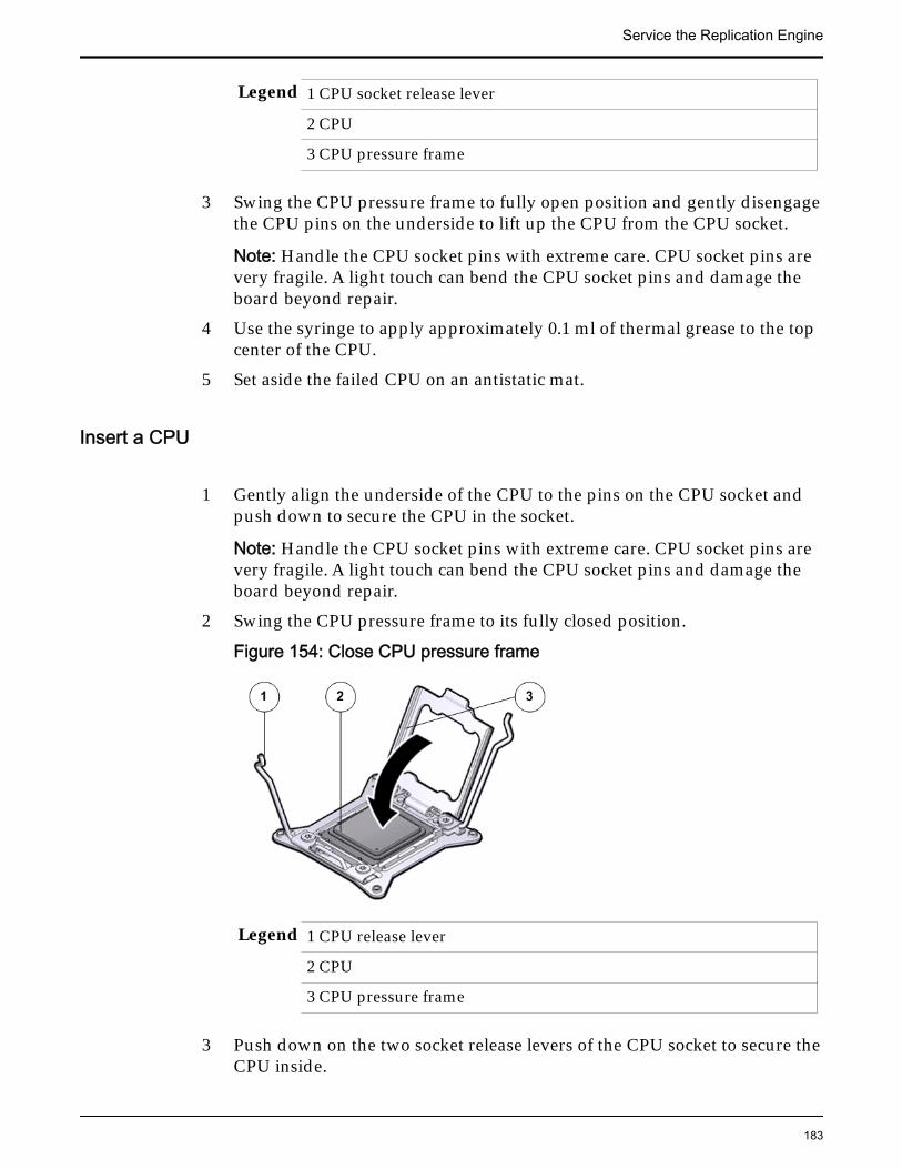
Legend 1 CPU socket release lever
2 CPU
3 CPU pressure frame
3 Swing the CPU pressure frame to fully open position and gently disengagethe CPU pins on the underside to lift up the CPU from the CPU socket.
Note: Handle the CPU socket pins with extreme care. CPU socket pins arevery fragile. A light touch can bend the CPU socket pins and damage theboard beyond repair.
4 Use the syringe to apply approximately 0.1 ml of thermal grease to the topcenter of the CPU.
5 Set aside the failed CPU on an antistatic mat.
Insert a CPU
1 Gently align the underside of the CPU to the pins on the CPU socket andpush down to secure the CPU in the socket.
Note: Handle the CPU socket pins with extreme care. CPU socket pins arevery fragile. A light touch can bend the CPU socket pins and damage theboard beyond repair.
2 Swing the CPU pressure frame to its fully closed position.
Figure 154: Close CPU pressure frame
Legend 1 CPU release lever
2 CPU
3 CPU pressure frame
3 Push down on the two socket release levers of the CPU socket to secure theCPU inside.
Service the Replication Engine
183

Insert a Heat Sink
1 Secure the heat sink over the CPU to the Replication Engine motherboardby inserting the four screws on the four sides of the heat sink.
Note: Ensure that the CPU is cleaned with an alcohol pad and freshthermal grease is applied, when installing a new heat sink, to preventoverheating and damage to the CPU.
Important: Ensure that the heat sink and the screws are aligned correctlyand the screws on diagonal ends of the heat sink are tightened first. Aslight force might need to be applied to push down the screwdriver whiletightening the screws to overcome the tension generated.
2 Tighten the four Phillips screws on the heat sink a few turns at a time in adiametrically opposed pattern using a Phillips Number 2 screwdriver.
Figure 155: Insert heat sink
Legend 1 Heat sink
2 Phillips screws that secure the heat sink
Lower the Drive Compartment
1 Rotate the drive compartment and backplane back into position inside theReplication Engine and ensure that the alignment pins engage.
Note: To confirm that the backplane is locked into position, listen for anaudible click or feel the backplane engage with the Replication Engine.
2 Secure the backplane inside the Replication Engine by inserting the fourPhillips Number 2 thumb screws on the four sides of the backplane andtightening them using a Phillips Number 2 screwdriver.
3 Reconnect all the cables that had been previously disconnected from thebackplane.Cables that must be reconnected include:
• SATA or drive cable
Service the Replication Engine
184

• Motherboard to HDD backplane cable
Figure 156: Reconnect cables to the backplane
Legend 1 SATA or drive cable
2 NV-DIMM cable
3 Drive compartment
4 Backplane boards
5 Motherboard to HDD backplane cable
Close the Replication Engine Top Cover
Place the top cover of the Replication Engine and tighten the two thumbscrews at the back of the Replication Engine that secure the top cover.
Service the Replication Engine
185

Figure 157: Close Replication Engine top cover
Legend 1 Thumb screws
2 Replication Engine top cover
3 Replication Engine
Complete the Component Replacement
1 Slide the Replication Engine back into rack position.
2 Re-connect the cables that were removed from the Replication Engine.
Note: The BIOS is set to automatically power on the Replication Engine,when power is applied.
Replace a Replication Engine LED Alarm AssemblyThe LED alarm assembly is a high-level status indicator of the Replication Engineand Replication Engine components. The LED alarm assembly also includes apower button to power on the Replication Engine. A failed LED alarm assemblywith a malfunctioning power button can cause problems when the ReplicationEngine is brought online and can also provide inaccurate status readings.
Note: Ensure that all power is removed from the Replication Engine beforeremoving or installing the LED alarm assembly. Disconnect the power cordsbefore performing the LED alarm assembly replacement procedure.
Service the Replication Engine
186

Prerequisites: • Ensure that you have a Phillips Number 2screwdriver with at least a 4-inch shaft.
• Before handling a component, touch a groundedsurface to discharge any static electricity.
• Attach an electrostatic discharge (ESD) wrist strap toyour wrist, and stand on an ESD mat while replacingcomponents.
Each Replication Engine has an LED alarm assembly that is located at the front ofthe Replication Engine. An LED alarm assembly is a field replaceable unit (FRU).Replacing an LED alarm assembly requires you to bring the Replication Engineoffline. The following figure shows Replication Engine LED board.
Figure 158: LED board
The following figure shows the front display panel of the LED alarm assembly:
Figure 159: LED assembly front display
Service the Replication Engine
187

Legend 1 Chassis identification LED or LocatorLED
5 Service processor LEDs
2 Service Action Required LED orCaution or Fault LED
6 Rear power supply LED
3 Motherboard or Power or OK LED 7 Fault or Alarm LEDs (Critical,Major, Minor)
4 Power switch 8 User Alarm LED
Note: The LED alarm assembly can be accessed only after removing the coverover the Replication Engine chassis.
Note: Replacement of the Replication Engine LED alarm assembly requiresassistance from Oracle Customer Support.
Note: To replace an LED alarm assembly, you must remove the ReplicationEngine from the rack and place it on a workbench because the rack rail blocks thescrew to remove the LED alarm assembly.
Procedure Overview
1 Remove the Replication Engine Power Supply Cords
2 Slide Replication Engine to Service Position
3 Disconnect Replication Engine Cabling
4 Remove Replication Engine Chassis From Rack
5 Remove Components From the Replication Engine
6 Remove an LED Alarm Assembly
7 Insert an LED Alarm Assembly
8 Insert Components on the Replication Engine
9 Insert the Replication Engine Onto the Rack
Remove the Replication Engine Power Supply Cords
Disconnect the power cords from both power supplies.
Service the Replication Engine
188
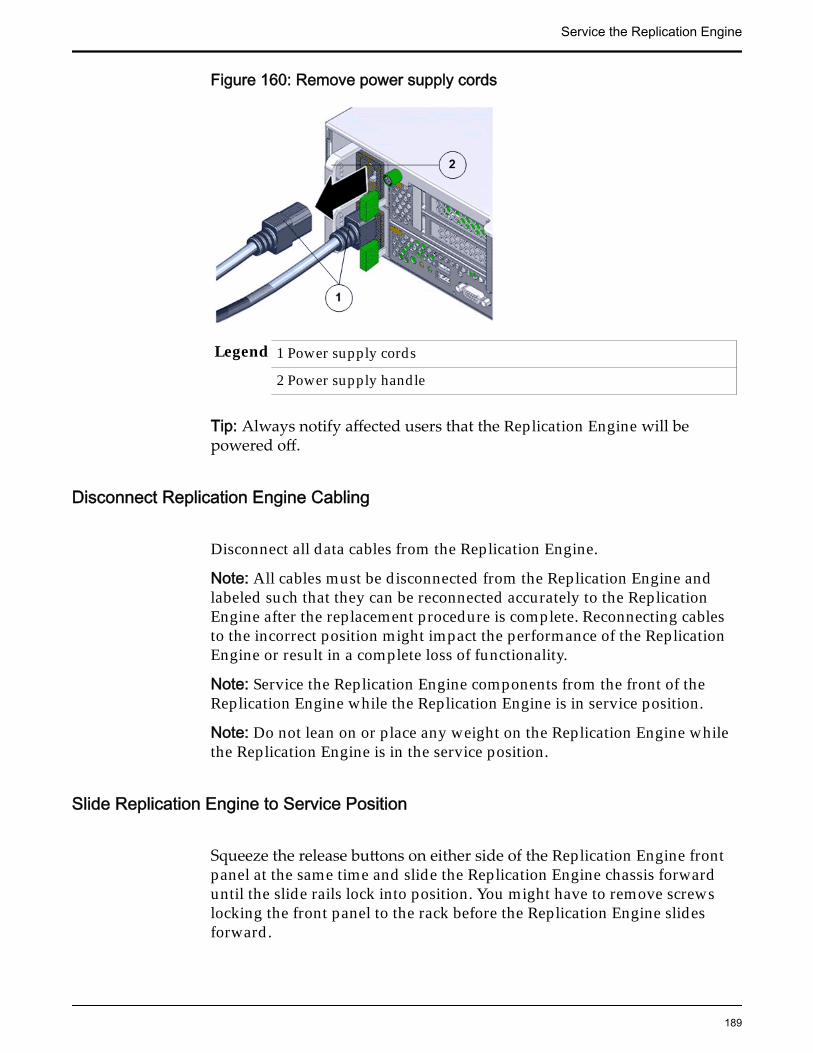
Figure 160: Remove power supply cords
Legend 1 Power supply cords
2 Power supply handle
Tip: Always notify affected users that the Replication Engine will bepowered off.
Disconnect Replication Engine Cabling
Disconnect all data cables from the Replication Engine.
Note: All cables must be disconnected from the Replication Engine andlabeled such that they can be reconnected accurately to the ReplicationEngine after the replacement procedure is complete. Reconnecting cablesto the incorrect position might impact the performance of the ReplicationEngine or result in a complete loss of functionality.
Note: Service the Replication Engine components from the front of theReplication Engine while the Replication Engine is in service position.
Note: Do not lean on or place any weight on the Replication Engine whilethe Replication Engine is in the service position.
Slide Replication Engine to Service Position
Squeeze the release buttons on either side of the Replication Engine frontpanel at the same time and slide the Replication Engine chassis forwarduntil the slide rails lock into position. You might have to remove screwslocking the front panel to the rack before the Replication Engine slidesforward.
Service the Replication Engine
189

Caution: Deploy any rack anti-tilt mechanism before releasing the releasebuttons and extending the Replication Engine chassis.
Figure 161: Slide the Replication Engine to service position
Legend 1 Rack
2 Replication Engine chassis
3 Release buttons
Important: Before you slide the Replication Engine chassis out, ensure thatthe cables do not interfere with the movement of the Replication Enginechassis. Although the cable management arm (CMA) is hinged so that youcan extend the Replication Engine chassis, all cables and cords must be outof the way when you service the Replication Engine components.
Remove Replication Engine Chassis From Rack
The following procedure is optional.
1 From the front of the Replication Engine, press on the slide-rail release tabson both sides at the front of the Replication Engine, and pull theReplication Engine out of the rack until is free of the rack rails.
Service the Replication Engine
190

Important: Oracle recommends not removing the Replication Engine fromthe rails for servicing the components. All components are designed forreplacement and servicing while the Replication Engine chassis is on therails. However, if you must remove the Replication Engine from the rack,disconnect the rear panel Replication Engine cables from the front with theReplication Engine in service position.
Note: A slide-rail release tab is located on each slide-rail of the ReplicationEngine.
2 With the help of a partner or a mechanical lift, place the Replication Engineon an antistatic surface on a workbench.
Remove Components From the Replication Engine
Note: Some components must be removed from the Replication Engine as aprerequisite for access while replacing the failed component.
Note: All components that are removed from the Replication Engine must beplaced on an antistatic surface or ESD qualified mat.
Open the Replication Engine Top Cover
1 Fully loosen the two captive thumb screws at the back of the top coverusing the Phillips number 2 screwdriver, if necessary.
Figure 162: Captive thumb screws to remove the top cover
Legend 1 Replication Engine top cover
2 Captive screws
2 Slide the top cover backwards 0.5 inches (13 mm) and lift the top coverstraight up and off the Replication Engine chassis.
Service the Replication Engine
191

Remove an Air Filter
1 At the front of the Replication Engine chassis, locate the air filter releasetabs.
2 Press the release tabs inwards at the same time to unlock the tabs anddisengage the air filter.
Figure 163: Air filter release tabs
Legend 1 Release tabs 2 Air filter
3 Carefully rotate the top of the air filter outwards and as the release tabsdisengage, lift out the filter.
Service the Replication Engine
192

Figure 164: Remove air filter
4 Set the air filter aside.
Raise the Drive Compartment to Service Position
1 Disconnect the cables attached to the backplane.Cables that must be disconnected include:
• SATA or drive cable
• Motherboard to HDD backplane cable
• USB board cable
Figure 165: Cables connected to the backplane
Service the Replication Engine
193

Legend 1 SATA or drive cable
2 NV-DIMM cables
3 Drive compartment
4 Backplane boards
5 Motherboard to HDD backplane cable
Note: The USB board cable is connected to the Replication Engine displaypanel.
Note: All cables attached to the backplane must be disconnected beforeraising the drive compartment. Otherwise, the cables might get damagedor tear due to unnecessary flexure or pull.
Note: Note the location of all the cable connections to the backplane forlater re-connection of the cables after the replacement procedure iscompleted.
Tip: Refer to the service label for more information on rotating the drivecompartment.
2 Disengage the backplane by loosening the four Phillips Number 2 thumbscrews on the four sides of the backplane using a Phillips Number 2screwdriver and rotate the backplane at a 90 degrees angle.
Figure 166: Disengaging the backplane
Service the Replication Engine
194

Legend 1 Thumb screws that secure the backplane
2 Backplane
Note: Use the screwdriver very carefully to avoid damaging the electricalcircuitry inside the Replication Engine.
3 Raise the backplane and drive compartment to the vertical position.
Figure 167: Drive compartment raised
Legend 1 Backplane
2 Drive compartment
3 Replication Engine motherboard
Remove an Air Duct
1 Remove the air duct by loosening the two brackets and the PhillipsNumber 2 thumb screws on both sides of the air duct.
Service the Replication Engine
195

Figure 168: Remove air duct
Legend 1 Screws that secure air duct
2 Air duct
Note: The brackets that secure the air duct are labeled L (left) and R (right).The left bracket slides forward and the right bracket slides back whenfacing the Replication Engine in the service position.
2 Lift up the air duct from the Replication Engine chassis and set it aside.The following figure shows a Replication Engine air duct:
Figure 169: Air duct
Service the Replication Engine
196

Remove an LED Alarm Assembly
1 Disconnect the cable from the cable clamp on the the side wall of theReplication Engine chassis.
2 Disconnect the cable from the motherboard.
Figure 170: Disconnect the LED alarm assembly cable
Legend 1 LED alarm assembly cable
3 Unscrew the two Phillips Number 2 screws at the back of the LED alarmassembly that secure the LED assembly to the Replication Engine frontpanel.
Figure 171: Screws to secure the LED alarm assembly
Service the Replication Engine
197
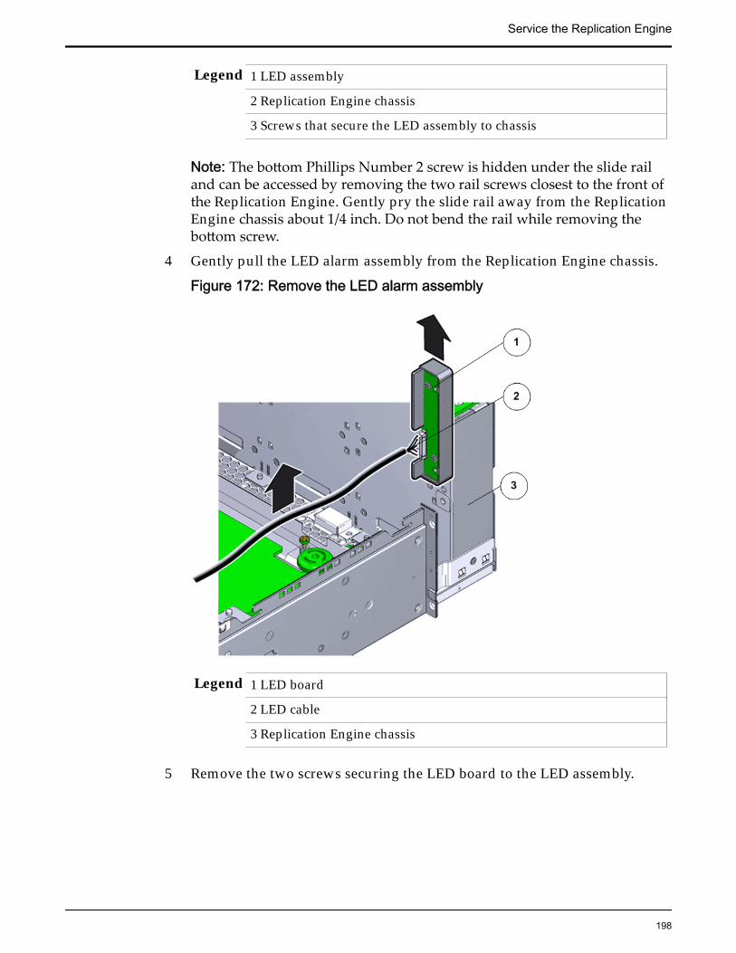
Legend 1 LED assembly
2 Replication Engine chassis
3 Screws that secure the LED assembly to chassis
Note: The bottom Phillips Number 2 screw is hidden under the slide railand can be accessed by removing the two rail screws closest to the front ofthe Replication Engine. Gently pry the slide rail away from the ReplicationEngine chassis about 1/4 inch. Do not bend the rail while removing thebottom screw.
4 Gently pull the LED alarm assembly from the Replication Engine chassis.
Figure 172: Remove the LED alarm assembly
Legend 1 LED board
2 LED cable
3 Replication Engine chassis
5 Remove the two screws securing the LED board to the LED assembly.
Service the Replication Engine
198

Figure 173: Detach LED board from the LED alarm assembly
Legend 1 LED alarm assembly
2 Screws securing the LED board to the LED alarm assembly
3 LED board
6 Lift the LED board from the LED assembly and set it aside.
Insert an LED Alarm Assembly
1 Unpack the component from its shipping carton.
Note: Place the component on an antistatic mat if it must be set aside forany reason.
2 Set the LED board into the LED assembly.
Service the Replication Engine
199
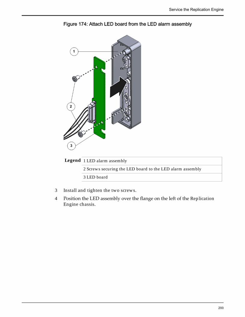
Figure 174: Attach LED board from the LED alarm assembly
Legend 1 LED alarm assembly
2 Screws securing the LED board to the LED alarm assembly
3 LED board
3 Install and tighten the two screws.
4 Position the LED assembly over the flange on the left of the ReplicationEngine chassis.
Service the Replication Engine
200

Figure 175: LED alarm assembly positioned over Replication Enginechassis
Legend 1 LED board
2 LED cable
3 Replication Engine chassis
5 Install and tighten the two screws to secure the LED alarm assembly ontothe Replication Engine chassis.
Figure 176: Screws to secure the LED alarm assembly
Service the Replication Engine
201
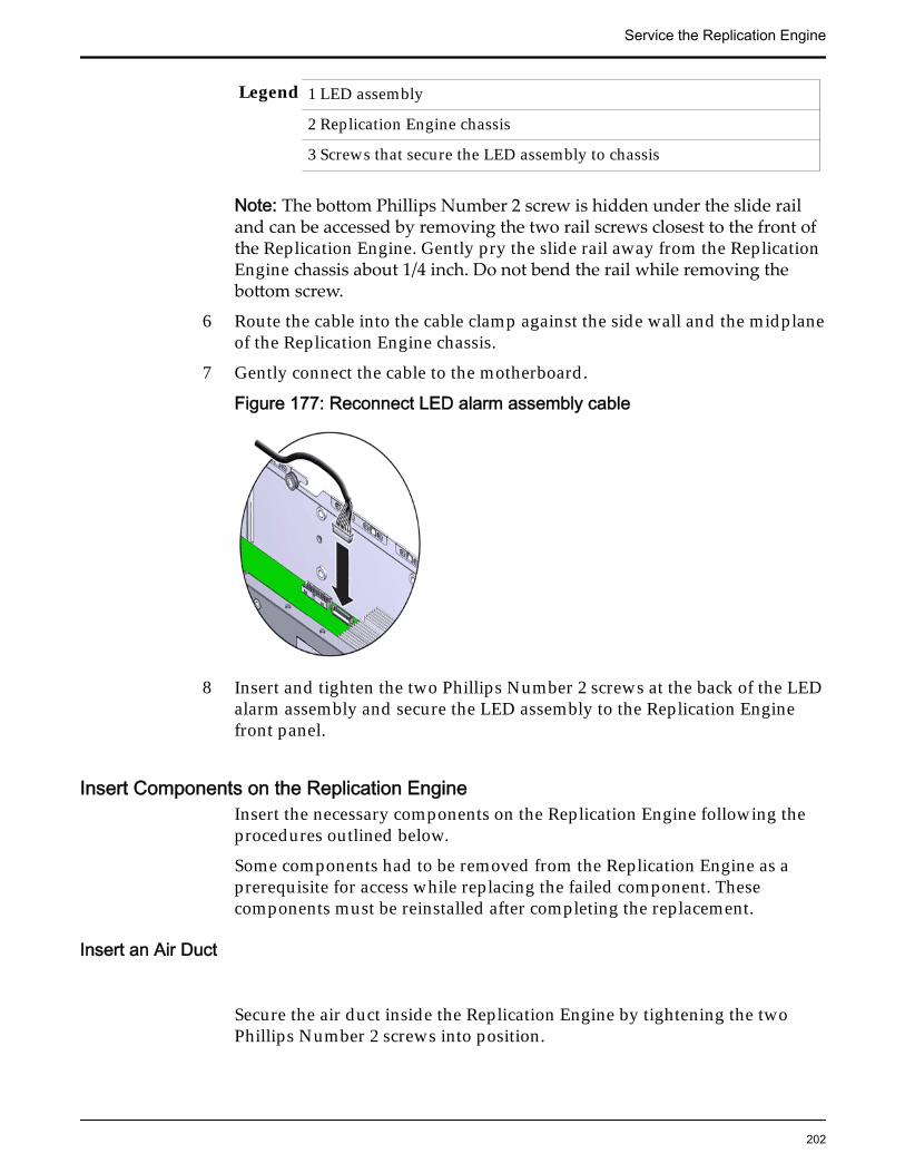
Legend 1 LED assembly
2 Replication Engine chassis
3 Screws that secure the LED assembly to chassis
Note: The bottom Phillips Number 2 screw is hidden under the slide railand can be accessed by removing the two rail screws closest to the front ofthe Replication Engine. Gently pry the slide rail away from the ReplicationEngine chassis about 1/4 inch. Do not bend the rail while removing thebottom screw.
6 Route the cable into the cable clamp against the side wall and the midplaneof the Replication Engine chassis.
7 Gently connect the cable to the motherboard.
Figure 177: Reconnect LED alarm assembly cable
8 Insert and tighten the two Phillips Number 2 screws at the back of the LEDalarm assembly and secure the LED assembly to the Replication Enginefront panel.
Insert Components on the Replication EngineInsert the necessary components on the Replication Engine following theprocedures outlined below.
Some components had to be removed from the Replication Engine as aprerequisite for access while replacing the failed component. Thesecomponents must be reinstalled after completing the replacement.
Insert an Air Duct
Secure the air duct inside the Replication Engine by tightening the twoPhillips Number 2 screws into position.
Service the Replication Engine
202
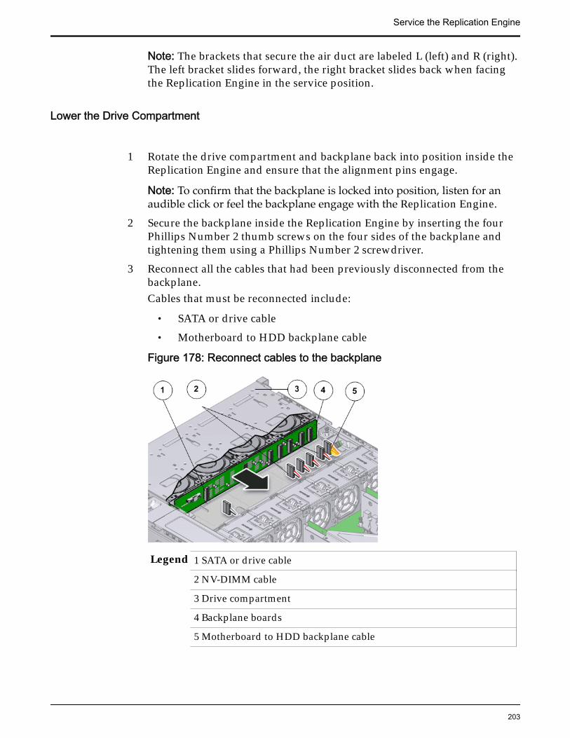
Note: The brackets that secure the air duct are labeled L (left) and R (right).The left bracket slides forward, the right bracket slides back when facingthe Replication Engine in the service position.
Lower the Drive Compartment
1 Rotate the drive compartment and backplane back into position inside theReplication Engine and ensure that the alignment pins engage.
Note: To confirm that the backplane is locked into position, listen for anaudible click or feel the backplane engage with the Replication Engine.
2 Secure the backplane inside the Replication Engine by inserting the fourPhillips Number 2 thumb screws on the four sides of the backplane andtightening them using a Phillips Number 2 screwdriver.
3 Reconnect all the cables that had been previously disconnected from thebackplane.Cables that must be reconnected include:
• SATA or drive cable
• Motherboard to HDD backplane cable
Figure 178: Reconnect cables to the backplane
Legend 1 SATA or drive cable
2 NV-DIMM cable
3 Drive compartment
4 Backplane boards
5 Motherboard to HDD backplane cable
Service the Replication Engine
203

Insert an Air Filter
1 Tilt the top of the air filter slightly towards you and insert the bottom twohooks into the mounting tabs.
Figure 179: Insert air filter
Important: Ensure that nothing interferes with the edges of the air filter andthat the air filter seats properly.
2 Press the top corners of the air filter to engage the top two air filter hookswith the top rail tabs.
3 Press both air filter release tabs until they lock in place.
Close the Replication Engine Top Cover
Place the top cover of the Replication Engine and tighten the two thumbscrews at the back of the Replication Engine that secure the top cover.
Service the Replication Engine
204

Figure 180: Close Replication Engine top cover
Legend 1 Thumb screws
2 Replication Engine top cover
3 Replication Engine
Insert the Replication Engine Onto the Rack
Insert the Replication Engine into the rack.Inserting the Replication Engine onto the rack includes the following tasks:
1 Lift up the Replication Engine Onto the Rack
2 Slide the Replication Engine back into Rack position
3 Reconnect the Replication Engine cabling and the CMA
4 Power on the Replication Engine
5 Verify the Replication Engine component status
Insert Replication Engine Chassis Onto Rack
With the help of a partner or a mechanical lift, engage the ReplicationEngine with the rack rails.
Service the Replication Engine
205

Caution: Do not use the power supply handles to lift the ReplicationEngine. Using the power supply handles to lift the Replication Engine candamage the power supplies and disrupt electrical power to the ReplicationEngine.
Slide Replication Engine to Rack Position
Slide the Replication Engine back into the rack.
Note: You must release the rail locking mechanism to slide the ReplicationEngine chassis back into the rack.
Reconnect Replication Engine Cabling
1 Reconnect all the data cables on the Replication Engine.
Note: Oracle Customer Support recommends labeling all cables connectedto the Replication Engine so that the cables can be reconnected accuratelyto the Replication Engine after the replacement procedure is complete.
2 Reconnect the CMA to the Replication Engine by attaching the release tabon the left and right side of the CMA.
Power On the Replication Engine
Power on the Replication Engine using the power button.
Note: As soon as the power cords are connected to the Replication Engine,standby power is applied. In standby power mode, the Power/OK LED onthe Replication Engine front panel blinks every five seconds or so.However, to apply main power to the Replication Engine, you must use thepower button. When main power is applied to the Replication Engine, thegreen Power/OK LED on the front panel of the Replication Engine blinkssteadily. When the Replication Engine BIOS has completed booting, the OKLED remains lit.
Replace a Replication Engine MotherboardThe motherboard is the primary circuit board of the Replication Engine. AllReplication Engine components are connected to the motherboard usingelectrical circuits and communicate with the motherboard to ensure normal
Service the Replication Engine
206

Replication Engine operation. A failed motherboard can cause the ReplicationEngine to fail and must be replaced as soon as possible.
Prerequisites: • Ensure that you have a Phillips Number 2screwdriver with at least a 4-inch shaft.
• Before handling a component, touch a groundedsurface to discharge any static electricity.
• Attach an electrostatic discharge (ESD) wrist strap toyour wrist, and stand on an ESD mat while replacingcomponents.
• Ensure that there is a workbench available to placethe Replication Engine chassis if it is removed fromthe rack for servicing.
• Ensure that you have thermal grease and syringeavailable to clean the CPU and heat sink during thereplacement procedure.
• Make sure that you have a Torx Number 10screwdriver.
• Ensure that there is a static protected surface orworkbench available to place the componentstemporarily when they are removed from themotherboard during the replacement process.
Each Replication Engine has a motherboard that is located on a tray at the bottomof the chassis. The Replication Engine motherboard is a field replaceable unit(FRU) on which the various Replication Engine components (FRUs and CRUs)are located. Replacing a motherboard requires you to bring the ReplicationEngine offline. The following figure shows the Replication Engine motherboard.
Figure 181: Replication Engine motherboard
Tip: Oracle Customer Support recommends not removing the Replication Enginechassis from the rack to minimize possible errors that might be caused during re-cabling. The motherboard replacement procedure can be completed while theReplication Engine chassis is in the service position inside the rack.
Service the Replication Engine
207

Note: The Replication Engine motherboard replacement can take approximatelyan hour to complete and requires assistance from Oracle Customer Supportbecause it involves removing several CRUs and FRUs from the failedmotherboard and installing them on the replacement motherboard.
Note: The motherboard can be accessed only after removing the cover over theReplication Engine chassis.
Caution: Ensure that all power is removed from the Replication Engine beforeremoving or installing the motherboard. Power off the Replication Engine anddisconnect the power cables before performing the motherboard replacementprocedure.
Note: Remove the DIMMs, NV-DIMMs, CPUs, and heat sinks from the failedmotherboard and secure it on the replacement motherboard only after thereplacement motherboard has been inserted and secured into the chassis. Notremoving these hardware components right away from the failed motherboardhas the following advantages:
• Hardware CRUs or FRUs that can be easily damaged like DIMMs, NV-DIMMs, CPUs, and heat sinks are handled only once during thereplacement procedure.
• The replacement motherboard that has been secured in the ReplicationEngine chassis provides the best support for installing the components.
• Moving the hardware components directly from the failed motherboard tothe replacement motherboard ensures that they are installed in the correctlocations.
Note: When the Replication Engine with the replacement motherboard isbrought online, the old motherboard continues to be displayed as a missingReplication Engine in the GUI for a brief span of time (approximately 20minutes) until the Replication Engine with the replacement motherboard is fullyinitialized.
Procedure Overview
1 Slide Replication Engine to Service Position
2 Remove the Replication Engine Power Supply Cords
3 Disconnect Replication Engine Cabling
4 Remove Replication Engine Chassis From Rack
5 Remove Components From the Replication Engine
6 Insert Components on the Replication Engine
7 Reconnect Replication Engine Cabling
8 Slide Replication Engine to Rack Position
9 Power On the Replication Engine
Service the Replication Engine
208

Remove the Replication Engine Power Supply Cords
Disconnect the power cords from both power supplies.
Figure 182: Remove power supply cords
Legend 1 Power supply cords
2 Power supply handle
Tip: Always notify affected users that the Replication Engine will bepowered off.
Slide Replication Engine to Service Position
Squeeze the release buttons on either side of the Replication Engine frontpanel at the same time and slide the Replication Engine chassis forwarduntil the slide rails lock into position. You might have to remove screwslocking the front panel to the rack before the Replication Engine slidesforward.
Caution: Deploy any rack anti-tilt mechanism before releasing the releasebuttons and extending the Replication Engine chassis.
Service the Replication Engine
209

Figure 183: Slide the Replication Engine to service position
Legend 1 Rack
2 Replication Engine chassis
3 Release buttons
Important: Before you slide the Replication Engine chassis out, ensure thatthe cables do not interfere with the movement of the Replication Enginechassis. Although the cable management arm (CMA) is hinged so that youcan extend the Replication Engine chassis, all cables and cords must be outof the way when you service the Replication Engine components.
Disconnect Replication Engine Cabling
Disconnect all data cables from the Replication Engine.
Note: All cables must be disconnected from the Replication Engine andlabeled such that they can be reconnected accurately to the ReplicationEngine after the replacement procedure is complete. Reconnecting cablesto the incorrect position might impact the performance of the ReplicationEngine or result in a complete loss of functionality.
Service the Replication Engine
210

Note: Service the Replication Engine components from the front of theReplication Engine while the Replication Engine is in service position.
Note: Do not lean on or place any weight on the Replication Engine whilethe Replication Engine is in the service position.
Remove Replication Engine Chassis From Rack
The following procedure is optional.
1 From the front of the Replication Engine, press on the slide-rail release tabson both sides at the front of the Replication Engine, and pull theReplication Engine out of the rack until is free of the rack rails.
Important: Oracle recommends not removing the Replication Engine fromthe rails for servicing the components. All components are designed forreplacement and servicing while the Replication Engine chassis is on therails. However, if you must remove the Replication Engine from the rack,disconnect the rear panel Replication Engine cables from the front with theReplication Engine in service position.
Note: A slide-rail release tab is located on each slide-rail of the ReplicationEngine.
2 With the help of a partner or a mechanical lift, place the Replication Engineon an antistatic surface on a workbench.
Remove Components From the Replication Engine
Note: Some components must be removed from the Replication Engine as aprerequisite for access while replacing the failed component.
Note: All components that are removed from the Replication Engine must beplaced on an antistatic surface or ESD qualified mat.
Open the Replication Engine Top Cover
1 Fully loosen the two captive thumb screws at the back of the top coverusing the Phillips number 2 screwdriver, if necessary.
Service the Replication Engine
211

Figure 184: Captive thumb screws to remove the top cover
Legend 1 Replication Engine top cover
2 Captive screws
2 Slide the top cover backwards 0.5 inches (13 mm) and lift the top coverstraight up and off the Replication Engine chassis.
Remove an Air Filter1 At the front of the Replication Engine chassis, locate the air filter release
tabs.
2 Press the release tabs inwards at the same time to unlock the tabs anddisengage the air filter.
Figure 185: Air filter release tabs
Service the Replication Engine
212

Legend 1 Release tabs 2 Air filter
3 Carefully rotate the top of the air filter outwards and as the release tabsdisengage, lift out the filter.
Figure 186: Remove air filter
4 Set the air filter aside.
Remove a Fan Module
1 Using your thumb and forefinger, grasp the removal tab and gently lift thefan module from the fan compartment.
Service the Replication Engine
213

Figure 187: Remove fan module
Legend 1 Replication Engine chassis
2 Fan compartment
3 Removal tab
4 Fan module
Note: Pulling the green tab from the middle releases the locking tab foreach individual fan.
Note: When removing a fan module, do not rock it back and forth. Rockingthe fan module can cause damage to the motherboard connectors.
2 Set the fan module aside.
Note: The fan compartment might come out when the last fan module isremoved.
Remove the Fan Compartment
1 Lift the fan compartment straight up and out of the Replication Enginechassis.
Service the Replication Engine
214

Figure 188: Remove fan compartment
Legend 1 Replication Engine chassis
2 Fan compartment
Note: All fan modules must be removed from the fan compartment beforeremoving the fan compartment.
2 Set the component aside.
Remove an Air Duct
1 Remove the air duct by loosening the two brackets and the PhillipsNumber 2 thumb screws on both sides of the air duct.
Service the Replication Engine
215

Figure 189: Remove air duct
Legend 1 Screws that secure air duct
2 Air duct
Note: The brackets that secure the air duct are labeled L (left) and R (right).The left bracket slides forward and the right bracket slides back whenfacing the Replication Engine in the service position.
2 Lift up the air duct from the Replication Engine chassis and set it aside.The following figure shows a Replication Engine air duct:
Figure 190: Air duct
Service the Replication Engine
216
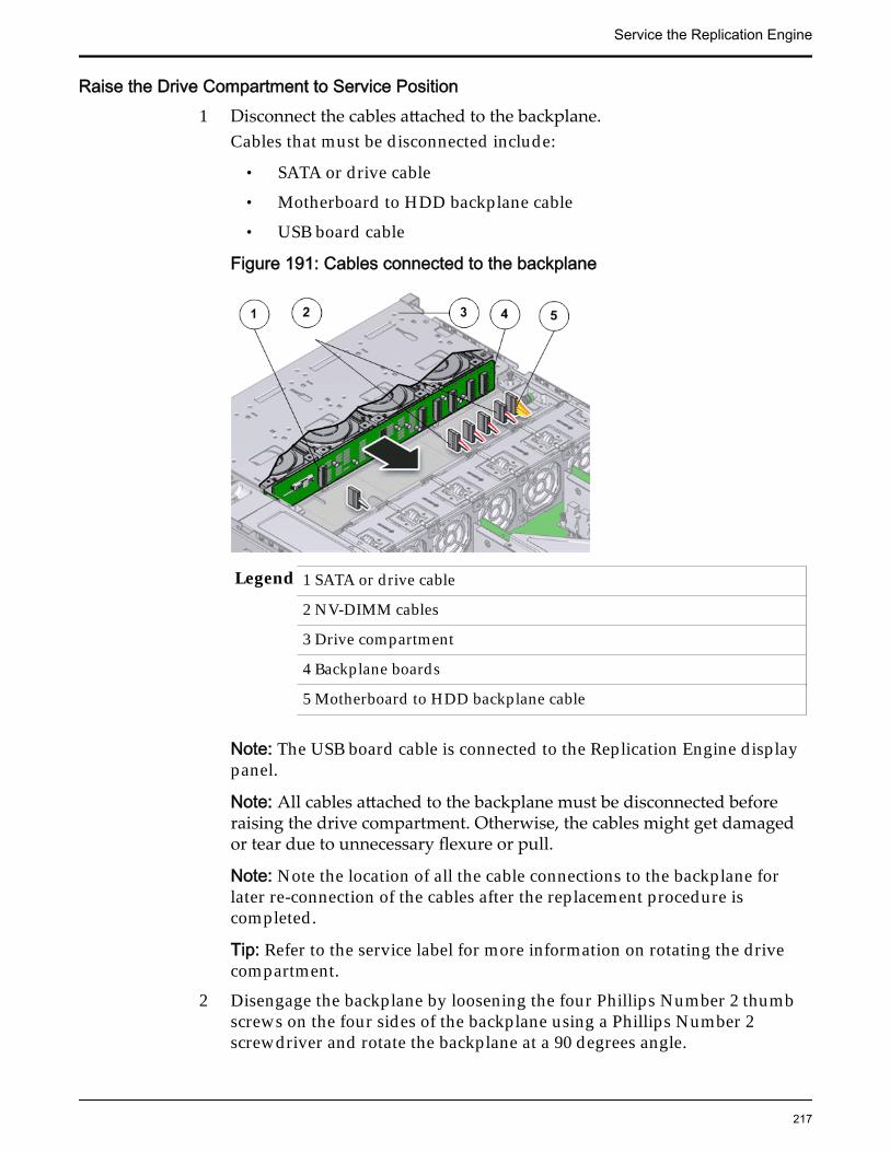
Raise the Drive Compartment to Service Position1 Disconnect the cables attached to the backplane.
Cables that must be disconnected include:
• SATA or drive cable
• Motherboard to HDD backplane cable
• USB board cable
Figure 191: Cables connected to the backplane
Legend 1 SATA or drive cable
2 NV-DIMM cables
3 Drive compartment
4 Backplane boards
5 Motherboard to HDD backplane cable
Note: The USB board cable is connected to the Replication Engine displaypanel.
Note: All cables attached to the backplane must be disconnected beforeraising the drive compartment. Otherwise, the cables might get damagedor tear due to unnecessary flexure or pull.
Note: Note the location of all the cable connections to the backplane forlater re-connection of the cables after the replacement procedure iscompleted.
Tip: Refer to the service label for more information on rotating the drivecompartment.
2 Disengage the backplane by loosening the four Phillips Number 2 thumbscrews on the four sides of the backplane using a Phillips Number 2screwdriver and rotate the backplane at a 90 degrees angle.
Service the Replication Engine
217

Figure 192: Disengaging the backplane
Legend 1 Thumb screws that secure the backplane
2 Backplane
Note: Use the screwdriver very carefully to avoid damaging the electricalcircuitry inside the Replication Engine.
3 Raise the backplane and drive compartment to the vertical position.
Figure 193: Drive compartment raised
Service the Replication Engine
218

Legend 1 Backplane
2 Drive compartment
3 Replication Engine motherboard
Remove a Riser
1 Disconnect any external cables that remain connected to the HBAs in therisers.
Note: Also disconnect any internal cables attached to the HBAs, if that willease removing the HBA.
Tip: Make a note of the positions of all existing cable connections beforeremoving any cables. Replacing HBAs or their cables into the incorrectposition in the riser may result in a loss of performance or functionality.
2 Note the position of the HBAs installed on the riser.
Tip: Make a note of the slot numbers of all existing HBAs before removingany HBAs.
3 Using a Phillips Number 2 screwdriver, loosen the two Phillips Number 2captive screws on either side of the riser that hold the riser to theReplication Engine motherboard.
Note: The riser on the opposite end of the power supply has a latch thatmust be disengaged to remove the riser from the Replication Enginechassis
Service the Replication Engine
219

Figure 194: Captive screws to secure the risers
Legend 1 Riser 3 with latch 3 Riser 1
2 Riser 2 4 Captive screws that secure riser
To remove riser 3, unlock the latch to release the riser from the ReplicationEngine motherboard.
Figure 195: Unlock Riser 3 latch
Service the Replication Engine
220

Legend 1 Riser 3 latch 3 HBA
2 Riser 3
4 Carefully pull the riser straight up and place it aside.
Figure 196: Remove riser
Legend 1 Riser
2 Replication Engine motherboard
Remove a Motherboard1 Using a Phillips Number 2 screwdriver, remove the four bus bar screws
that secure the power distribution board (PDB) assembly onto themotherboard.
Service the Replication Engine
221

Figure 197: Phillips screwdriver to remove PDB screws
Legend 1 PDB cable bundle
2 Motherboard cables
3 Phillips screws that secure the PDB to motherboard
4 Thumb screws that secure the motherboard to the chassis
5 Replication Engine motherboard
Tip: Disconnect all remaining cables and move them out of the way.2 Fully loosen the captive screw at the front of the motherboard.3 Grasp the two motherboard handles or thumb screws and slide the
motherboard backwards off of the alignment pins.
Figure 198: Handles to lift up the motherboard
Service the Replication Engine
222
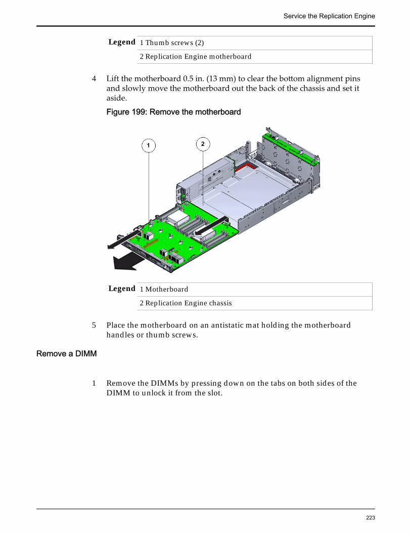
Legend 1 Thumb screws (2)
2 Replication Engine motherboard
4 Lift the motherboard 0.5 in. (13 mm) to clear the bottom alignment pinsand slowly move the motherboard out the back of the chassis and set itaside.
Figure 199: Remove the motherboard
Legend 1 Motherboard
2 Replication Engine chassis
5 Place the motherboard on an antistatic mat holding the motherboardhandles or thumb screws.
Remove a DIMM
1 Remove the DIMMs by pressing down on the tabs on both sides of theDIMM to unlock it from the slot.
Service the Replication Engine
223

Figure 200: Remove DIMMs
Legend 1 Tabs to release DIMMs
2 DIMM
3 DIMM slot
Note: While inserting or removing DIMMs, ensure that there is nointerference with the cables. Pulling or pressing down on the cables mightcause damage to the cables during the replacement procedure.
2 Lift out the DIMM and set aside on an antistatic mat.
Note: Visually inspect the slots and the memory for physical damage bychecking for cracked or broken plastic in the slot.
Note: Sometimes memory might fault because of dust or improperalignment or damaged slots. Use only compressed air to dust the memory.
Remove a Heat Sink
1 Remove the access window on the air duct to remove the heat sink andCPU.
2 Loosen the four Phillips screws on the four sides of the heat sink thatsecure the heat sink to the Replication Engine chassis a few turns at a timein a diametrically opposed pattern using a Phillips Number 2 screwdriver.
Service the Replication Engine
224

Figure 201: Loosen four screws to remove heat sink
Legend 1 Heat sink 2 Phillips screws that secure the heat sink
Note: Loosen one screw, then loosen the screw opposite that screw on theheat sink to prevent it from warping the motherboard on which it ismounted.
3 Gently twist the heat sink left and right, while pulling upward, to separatethe heat sink from the top of the CPU.
Note: A thin layer of thermal grease separates the heat sink and the CPU.This thermal grease also acts as an adhesive.
Caution: Do not allow the thermal grease to contaminate the work space orother components.
4 Lift up the failed heat sink and set aside on an antistatic mat.
5 Visually inspect the failed heat sink to verify if the thermal grease hasdried out and use an alcohol pad to clean the thermal grease from theunderside of the heat sink.
Note: Be careful not to get the thermal grease on your fingers, as this couldresult in contamination of components.
Caution: Failure to clean the heat sink before removing the CPU can resultin the accidental contamination of the CPU socket or other components.
Remove a CPU
1 Disengage the CPU release lever on the right side of the CPU socket(viewing the Replication Engine from the front) by pushing down andmoving it to the side away from the CPU, and then rotating the leverupward.
Service the Replication Engine
225

Figure 202: Disengage CPU release lever
Legend 1 CPU release lever
2 CPU
3 CPU socket
Note: This exposes the CPU inside the CPU socket.
Caution: The correct CPU removal or replacement tool must be used toremove and replace a CPU. Otherwise, the CPU or the CPU socket mightbe damaged. The correct CPU removal/replacement tool is included in thebox with the replacement CPU. Additionally, both removal or replacementtools ship with replacement motherboards.
The model for the CPUs in the Oracle FS System Replication Engine isE5-2620 V2 (8 core processor) and requires a CPU removal tool that is colorcoded green.
Figure 203: CPU removal tool
Service the Replication Engine
226
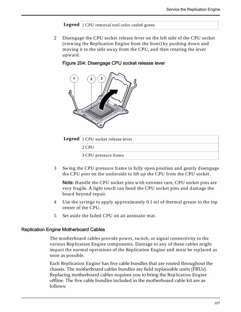
Legend 1 CPU removal tool color coded green
2 Disengage the CPU socket release lever on the left side of the CPU socket(viewing the Replication Engine from the front) by pushing down andmoving it to the side away from the CPU, and then rotating the leverupward.
Figure 204: Disengage CPU socket release lever
Legend 1 CPU socket release lever
2 CPU
3 CPU pressure frame
3 Swing the CPU pressure frame to fully open position and gently disengagethe CPU pins on the underside to lift up the CPU from the CPU socket.
Note: Handle the CPU socket pins with extreme care. CPU socket pins arevery fragile. A light touch can bend the CPU socket pins and damage theboard beyond repair.
4 Use the syringe to apply approximately 0.1 ml of thermal grease to the topcenter of the CPU.
5 Set aside the failed CPU on an antistatic mat.
Replication Engine Motherboard Cables
The motherboard cables provide power, switch, or signal connectivity to thevarious Replication Engine components. Damage to any of these cables mightimpact the normal operations of the Replication Engine and must be replaced assoon as possible.
Each Replication Engine has five cable bundles that are routed throughout thechassis. The motherboard cables bundles are field replaceable units (FRUs).Replacing motherboard cables requires you to bring the Replication Engineoffline. The five cable bundles included in the motherboard cable kit are asfollows:
Service the Replication Engine
227
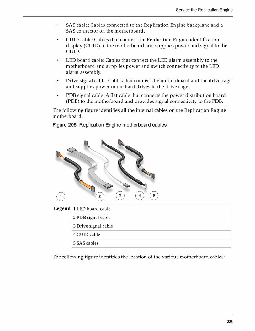
• SAS cable: Cables connected to the Replication Engine backplane and aSAS connector on the motherboard.
• CUID cable: Cables that connect the Replication Engine identificationdisplay (CUID) to the motherboard and supplies power and signal to theCUID.
• LED board cable: Cables that connect the LED alarm assembly to themotherboard and supplies power and switch connectivity to the LEDalarm assembly.
• Drive signal cable: Cables that connect the motherboard and the drive cageand supplies power to the hard drives in the drive cage.
• PDB signal cable: A flat cable that connects the power distribution board(PDB) to the motherboard and provides signal connectivity to the PDB.
The following figure identifies all the internal cables on the Replication Enginemotherboard.
Figure 205: Replication Engine motherboard cables
Legend 1 LED board cable
2 PDB signal cable
3 Drive signal cable
4 CUID cable
5 SAS cables
The following figure identifies the location of the various motherboard cables:
Service the Replication Engine
228

Figure 206: Location of the motherboard cables
Legend 1 PDB signal cable
2 CUID cable
3 Drive signal cable
4 SAS cables
5 LED board cable
6 Drive backplane power and monitoring cable
Remove Motherboard Cables
1 Gently disconnect the motherboard cable from its connector.
Note: Replacing a motherboard cable might require you to remove somecomponents from the motherboard based on the location of the cable thatyou are replacing. Make sure that you have adequate access to the cableconnectors while replacing the motherboard cable.
2 Set the cable aside on an antistatic mat.
Remove a Power Distribution Board (PDB) Cover1 Fully loosen the captive screw and gently lift up the cover over the PDB by
pressing the tabs on the cover and set the cover aside.
Service the Replication Engine
229

Figure 207: Remove PDB cover
2 Gently disconnect the PDB flat signal cable and the PSU duct when you liftup the PDB cover.
Figure 208: Disconnect PDB flat cable
Legend 1 PDB flat signal cable that connects the PDB to the motherboard
2 PDB bus bars
3 PDB
4 PDB cage
Insert Components on the Replication EngineInsert the necessary components on the Replication Engine following theprocedures outlined below.
Service the Replication Engine
230

Some components had to be removed from the Replication Engine as aprerequisite for access while replacing the failed component. Thesecomponents must be reinstalled after completing the replacement.
Insert a Power Distribution Board (PDB) Cover1 Reconnect the PDB flat signal cable and the PSU duct.
Figure 209: Reconnect PDB PSU duct
Legend 1 Power supply duct
2 PDB cover
2 Lower the cover over the PDB and the bus bars.
Figure 210: Install PDB cover
Service the Replication Engine
231

Legend 1 PDB cover
2 Power supply duct
3 PDB board
3 Tighten the captive screw to secure the cover to the motherboard and thechassis.
Figure 211: Secure PDB cover with captive screw
Legend 1 PDB captive screw
2 Power supply duct
3 PDB cover
Insert Motherboard Cables
Gently reconnect the motherboard cable to its connectors at both ends.
Insert a DIMM
Press the DIMM fully into the DIMM slot and ensure that the tabs on bothsides of the DIMM are locked.
Service the Replication Engine
232

Figure 212: Insert Replication Engine DIMM
Legend 1 DIMM
2 Tabs to secure DIMMs
3 DIMM notch aligns with the DIMM slots
Note: While inserting DIMMs, ensure that there is no interference with thecables. Pulling or pressing down on the cables might cause damage to thecables during the replacement procedure.
Figure 213: DIMM alignment over DIMM slots
Important: Ensure that the notch in the DIMM lines up with the key in theslot.
Note: Replace only one DIMM at a time to make sure that they are insertedinto the correct slots. Attempting to insert multiple DIMMs into the slotsmight damage the DIMMs due to excessive flexure.
Note: Never leave a DIMM slot unpopulated. Insert fillers into empty slotsto ensure proper air flow inside the Replication Engine.
Insert a CPU
Service the Replication Engine
233

1 Gently align the underside of the CPU to the pins on the CPU socket andpush down to secure the CPU in the socket.
Note: Handle the CPU socket pins with extreme care. CPU socket pins arevery fragile. A light touch can bend the CPU socket pins and damage theboard beyond repair.
2 Swing the CPU pressure frame to its fully closed position.
Figure 214: Close CPU pressure frame
Legend 1 CPU release lever
2 CPU
3 CPU pressure frame
3 Push down on the two socket release levers of the CPU socket to secure theCPU inside.
Insert a Heat Sink
1 Secure the heat sink over the CPU to the Replication Engine motherboardby inserting the four screws on the four sides of the heat sink.
Note: Ensure that the CPU is cleaned with an alcohol pad and freshthermal grease is applied, when installing a new heat sink, to preventoverheating and damage to the CPU.
Important: Ensure that the heat sink and the screws are aligned correctlyand the screws on diagonal ends of the heat sink are tightened first. Aslight force might need to be applied to push down the screwdriver whiletightening the screws to overcome the tension generated.
2 Tighten the four Phillips screws on the heat sink a few turns at a time in adiametrically opposed pattern using a Phillips Number 2 screwdriver.
Service the Replication Engine
234
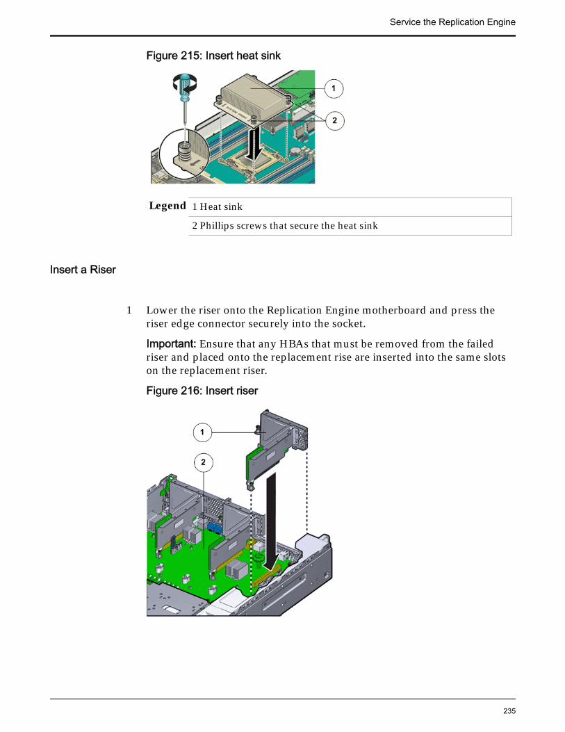
Figure 215: Insert heat sink
Legend 1 Heat sink
2 Phillips screws that secure the heat sink
Insert a Riser
1 Lower the riser onto the Replication Engine motherboard and press theriser edge connector securely into the socket.
Important: Ensure that any HBAs that must be removed from the failedriser and placed onto the replacement rise are inserted into the same slotson the replacement riser.
Figure 216: Insert riser
Service the Replication Engine
235

Legend 1 Riser
2 Replication Engine motherboard
2 After the riser is seated properly inside the Replication Engine, tighten thetwo captive Phillips screws on both sides of the riser to secure the riser onthe Replication Engine motherboard.
Figure 217: Captive screws to secure risers to the motherboard
Legend 1 Riser 3 with latch 3 Riser 1
2 Riser 2 4 Captive screws
To install riser 3, lock the latch to secure the riser to the Replication Enginemotherboard.
Service the Replication Engine
236

Figure 218: Riser 3 latch locked
Legend 1 Riser 3 latch 3 HBA
2 Riser 3
3 Reconnect any previously removed internal or external cables to any HBAsinstalled in the riser.
4 Repeat the above steps for any additional risers that you are installing.
Insert a Motherboard
1 Unpack the component from its shipping carton.
Note: Place the component on an antistatic mat if it must be set aside forany reason.
2 Use the two thumb screws or handles to place the motherboard onto theReplication Engine chassis gently.
Note: Due to the tight fit inside the Replication Engine chassis, care mustbe taken while inserting the motherboard into the chassis. Do not flex thePDB board and ensure that the screw holes on the chassis align correctlywith the motherboard while inserting the motherboard into the ReplicationEngine chassis.
3 Lift the motherboard gently by the handles to a height of about 0.5 in. (13mm) and slowly move the motherboard forward into the chassis from therear.
Service the Replication Engine
237

4 When there is about 1.5 inches (36 millimeters) to go, lower themotherboard onto the bottom alignment pins.
5 Slowly slide the motherboard forward until it drops, engaging the bottomalignment pins.
6 Continue to slide the motherboard forward until it seats.
Note: The back of the motherboard must be flush with the back of thechassis. Additionally, the four holes in the motherboard must align withthe four holes in the bus bars.
7 Tighten the captive screws, the four bus bar screws, and reconnect thecables that you previously disconnected.
Figure 219: Secure the motherboard
Legend 1 PDB cable bundle
2 Motherboard cables
3 Bus bar screws that secure the PDB to motherboard
4 Thumb screws or handles to remove and insert the motherboard tothe chassis
5 Replication Engine motherboard
Lower the Drive Compartment1 Rotate the drive compartment and backplane back into position inside the
Replication Engine and ensure that the alignment pins engage.
Note: To confirm that the backplane is locked into position, listen for anaudible click or feel the backplane engage with the Replication Engine.
Service the Replication Engine
238
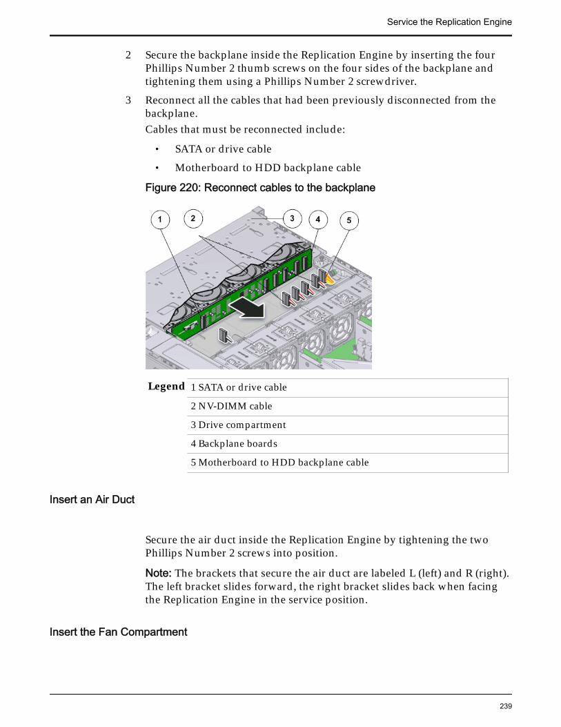
2 Secure the backplane inside the Replication Engine by inserting the fourPhillips Number 2 thumb screws on the four sides of the backplane andtightening them using a Phillips Number 2 screwdriver.
3 Reconnect all the cables that had been previously disconnected from thebackplane.Cables that must be reconnected include:
• SATA or drive cable
• Motherboard to HDD backplane cable
Figure 220: Reconnect cables to the backplane
Legend 1 SATA or drive cable
2 NV-DIMM cable
3 Drive compartment
4 Backplane boards
5 Motherboard to HDD backplane cable
Insert an Air Duct
Secure the air duct inside the Replication Engine by tightening the twoPhillips Number 2 screws into position.
Note: The brackets that secure the air duct are labeled L (left) and R (right).The left bracket slides forward, the right bracket slides back when facingthe Replication Engine in the service position.
Insert the Fan Compartment
Service the Replication Engine
239

1 Move any loose cables so that they are against the Replication Enginechassis walls.
2 Align the fan compartment to where it installs into the Replication Enginechassis.
Figure 221: Insert the fan compartment
Legend 1 Fan compartment
2 Replication Engine chassis
Note: The single arrow on the right end of the fan compartment aligns withthe single arrow on the power supply bay.
3 Slowly lower the fan compartment into the Replication Engine chassis,gently working the cables into the gaps between the fan compartment andthe chassis walls.
4 Verify that the fan compartment is properly seated, no cables are pinched,and the top surfaces of the fan compartment are flush with the ReplicationEngine chassis.
Insert a Fan Module
Insert the replacement fan module into the Replication Engine.
Service the Replication Engine
240

Figure 222: Insert fan module
Legend 1 Replication Engine chassis
2 Fan compartment
3 Fan module
Note: Press down on the fan module and apply firm pressure to fully seatthe fan module into the fan compartment. The fan modules are notched toensure that they are installed in the correct orientation.
Note: Repeat for each additional fan module.
Insert an Air Filter1 Tilt the top of the air filter slightly towards you and insert the bottom two
hooks into the mounting tabs.
Service the Replication Engine
241

Figure 223: Insert air filter
Important: Ensure that nothing interferes with the edges of the air filter andthat the air filter seats properly.
2 Press the top corners of the air filter to engage the top two air filter hookswith the top rail tabs.
3 Press both air filter release tabs until they lock in place.
Close the Replication Engine Top Cover
Place the top cover of the Replication Engine and tighten the two thumbscrews at the back of the Replication Engine that secure the top cover.
Service the Replication Engine
242
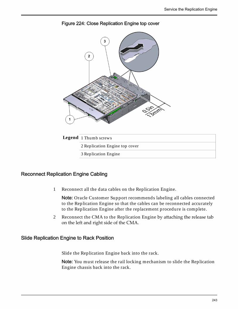
Figure 224: Close Replication Engine top cover
Legend 1 Thumb screws
2 Replication Engine top cover
3 Replication Engine
Reconnect Replication Engine Cabling
1 Reconnect all the data cables on the Replication Engine.
Note: Oracle Customer Support recommends labeling all cables connectedto the Replication Engine so that the cables can be reconnected accuratelyto the Replication Engine after the replacement procedure is complete.
2 Reconnect the CMA to the Replication Engine by attaching the release tabon the left and right side of the CMA.
Slide Replication Engine to Rack Position
Slide the Replication Engine back into the rack.
Note: You must release the rail locking mechanism to slide the ReplicationEngine chassis back into the rack.
Service the Replication Engine
243

Power On the Replication EnginePower on the Replication Engine using the power button.
Note: As soon as the power cords are connected to the Replication Engine,standby power is applied. In standby power mode, the Power/OK LED onthe Replication Engine front panel blinks every five seconds or so.However, to apply main power to the Replication Engine, you must use thepower button. When main power is applied to the Replication Engine, thegreen Power/OK LED on the front panel of the Replication Engine blinkssteadily. When the Replication Engine BIOS has completed booting, the OKLED remains lit.
Replace Replication Engine Motherboard CablesThe motherboard cables provide power, switch, or signal connectivity to thevarious Replication Engine components. Damage to any of these cables mightimpact the normal operations of the Replication Engine and must be replaced assoon as possible.
Prerequisites: • Ensure that you have a Phillips Number 2screwdriver with at least a 4-inch shaft.
• Before handling a component, touch a groundedsurface to discharge any static electricity.
• Attach an electrostatic discharge (ESD) wrist strap toyour wrist, and stand on an ESD mat while replacingcomponents.
Each Replication Engine has five cable bundles that are routed throughout thechassis. The motherboard cables bundles are field replaceable units (FRUs).Replacing motherboard cables requires you to bring the Replication Engineoffline. The five cable bundles included in the motherboard cable kit are asfollows:
• SAS cable: Cables connected to the Replication Engine backplane and aSAS connector on the motherboard.
• USB cable: Cables that connect the Replication Engine USB ports.
• LED board cable: Cables that connect the LED alarm assembly to themotherboard and supplies power and switch connectivity to the LEDalarm assembly.
• Drive signal cable: Cables that connect the motherboard and the drive cageand supplies power to the hard drives in the drive cage.
• PDB signal cable: A flat cable that connects the power distribution board(PDB) to the motherboard and provides signal connectivity to the PDB.
The following figure identifies all the internal cables on the Replication Enginemotherboard.
Service the Replication Engine
244

Figure 225: Replication Engine motherboard cables
Legend 1 LED board cable
2 PDB signal cable
3 Drive signal cable
4 CUID cable USB cable
5 SAS cables
The following figure identifies the location of the various motherboard cables:
Figure 226: Location of the motherboard cables
Service the Replication Engine
245

Legend 1 PDB signal cable
2 CUID cable USB cable
3 Drive signal cable
4 SAS cables
5 LED board cable
6 Drive backplane power and monitoring cable
Note: The motherboard cables can be accessed only after removing the coverover the Replication Engine chassis.
Note: Because Replication Engine motherboard cable replacement can take sometime to complete to identify the cables for replacement, the Replication Engineshould be placed on a workbench for servicing rather than inside the rack forconvenience.
Caution: Replacement of the Replication Engine motherboard cables requiresassistance from Oracle Customer Support.
Caution: Ensure that all power is removed from the Replication Engine beforeremoving or installing the motherboard. Disconnect the power cords beforeperforming the motherboard replacement procedure.
Procedure Overview
1 Slide Replication Engine to Service Position
2 Remove the Replication Engine Power Supply Cords
3 Disconnect Replication Engine Cabling
4 Remove Replication Engine Chassis From Rack
5 Remove Components From the Replication Engine
6 Remove Motherboard Cables
7 Insert Motherboard Cables
8 Insert Components on the Replication Engine
9 Insert the Replication Engine Onto the Rack
Remove the Replication Engine Power Supply Cords
Disconnect the power cords from both power supplies.
Service the Replication Engine
246

Figure 227: Remove power supply cords
Legend 1 Power supply cords
2 Power supply handle
Tip: Always notify affected users that the Replication Engine will bepowered off.
Disconnect Replication Engine Cabling
Disconnect all data cables from the Replication Engine.
Note: All cables must be disconnected from the Replication Engine andlabeled such that they can be reconnected accurately to the ReplicationEngine after the replacement procedure is complete. Reconnecting cablesto the incorrect position might impact the performance of the ReplicationEngine or result in a complete loss of functionality.
Note: Service the Replication Engine components from the front of theReplication Engine while the Replication Engine is in service position.
Note: Do not lean on or place any weight on the Replication Engine whilethe Replication Engine is in the service position.
Slide Replication Engine to Service Position
Squeeze the release buttons on either side of the Replication Engine frontpanel at the same time and slide the Replication Engine chassis forwarduntil the slide rails lock into position. You might have to remove screwslocking the front panel to the rack before the Replication Engine slidesforward.
Service the Replication Engine
247

Caution: Deploy any rack anti-tilt mechanism before releasing the releasebuttons and extending the Replication Engine chassis.
Figure 228: Slide the Replication Engine to service position
Legend 1 Rack
2 Replication Engine chassis
3 Release buttons
Important: Before you slide the Replication Engine chassis out, ensure thatthe cables do not interfere with the movement of the Replication Enginechassis. Although the cable management arm (CMA) is hinged so that youcan extend the Replication Engine chassis, all cables and cords must be outof the way when you service the Replication Engine components.
Remove Replication Engine Chassis From Rack
The following procedure is optional.
1 From the front of the Replication Engine, press on the slide-rail release tabson both sides at the front of the Replication Engine, and pull theReplication Engine out of the rack until is free of the rack rails.
Service the Replication Engine
248

Important: Oracle recommends not removing the Replication Engine fromthe rails for servicing the components. All components are designed forreplacement and servicing while the Replication Engine chassis is on therails. However, if you must remove the Replication Engine from the rack,disconnect the rear panel Replication Engine cables from the front with theReplication Engine in service position.
Note: A slide-rail release tab is located on each slide-rail of the ReplicationEngine.
2 With the help of a partner or a mechanical lift, place the Replication Engineon an antistatic surface on a workbench.
Remove Components From the Replication Engine
Note: Some components must be removed from the Replication Engine as aprerequisite for access while replacing the failed component.
Note: All components that are removed from the Replication Engine must beplaced on an antistatic surface or ESD qualified mat.
Open the Replication Engine Top Cover
1 Fully loosen the two captive thumb screws at the back of the top coverusing the Phillips number 2 screwdriver, if necessary.
Figure 229: Captive thumb screws to remove the top cover
Legend 1 Replication Engine top cover
2 Captive screws
2 Slide the top cover backwards 0.5 inches (13 mm) and lift the top coverstraight up and off the Replication Engine chassis.
Service the Replication Engine
249

Remove a Fan Module
1 Using your thumb and forefinger, grasp the removal tab and gently lift thefan module from the fan compartment.
Figure 230: Remove fan module
Legend 1 Replication Engine chassis
2 Fan compartment
3 Removal tab
4 Fan module
Note: Pulling the green tab from the middle releases the locking tab foreach individual fan.
Note: When removing a fan module, do not rock it back and forth. Rockingthe fan module can cause damage to the motherboard connectors.
2 Set the fan module aside.
Note: The fan compartment might come out when the last fan module isremoved.
Remove the Fan Compartment
Service the Replication Engine
250

1 Lift the fan compartment straight up and out of the Replication Enginechassis.
Figure 231: Remove fan compartment
Legend 1 Replication Engine chassis
2 Fan compartment
Note: All fan modules must be removed from the fan compartment beforeremoving the fan compartment.
2 Set the component aside.
Remove Motherboard Cables
1 Gently disconnect the motherboard cable from its connector.
Note: Replacing a motherboard cable might require you to remove somecomponents from the motherboard based on the location of the cable thatyou are replacing. Make sure that you have adequate access to the cableconnectors while replacing the motherboard cable.
2 Set the cable aside on an antistatic mat.
Insert Motherboard Cables
Gently reconnect the motherboard cable to its connectors at both ends.
Service the Replication Engine
251

Insert Components on the Replication EngineInsert the necessary components on the Replication Engine following theprocedures outlined below.
Some components had to be removed from the Replication Engine as aprerequisite for access while replacing the failed component. Thesecomponents must be reinstalled after completing the replacement.
Insert the Fan Compartment
1 Move any loose cables so that they are against the Replication Enginechassis walls.
2 Align the fan compartment to where it installs into the Replication Enginechassis.
Figure 232: Insert the fan compartment
Legend 1 Fan compartment
2 Replication Engine chassis
Note: The single arrow on the right end of the fan compartment aligns withthe single arrow on the power supply bay.
3 Slowly lower the fan compartment into the Replication Engine chassis,gently working the cables into the gaps between the fan compartment andthe chassis walls.
4 Verify that the fan compartment is properly seated, no cables are pinched,and the top surfaces of the fan compartment are flush with the ReplicationEngine chassis.
Service the Replication Engine
252
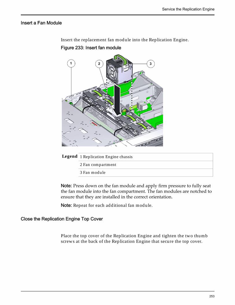
Insert a Fan Module
Insert the replacement fan module into the Replication Engine.
Figure 233: Insert fan module
Legend 1 Replication Engine chassis
2 Fan compartment
3 Fan module
Note: Press down on the fan module and apply firm pressure to fully seatthe fan module into the fan compartment. The fan modules are notched toensure that they are installed in the correct orientation.
Note: Repeat for each additional fan module.
Close the Replication Engine Top Cover
Place the top cover of the Replication Engine and tighten the two thumbscrews at the back of the Replication Engine that secure the top cover.
Service the Replication Engine
253

Figure 234: Close Replication Engine top cover
Legend 1 Thumb screws
2 Replication Engine top cover
3 Replication Engine
Insert the Replication Engine Onto the Rack
Insert the Replication Engine into the rack.Inserting the Replication Engine onto the rack includes the following tasks:
1 Lift up the Replication Engine Onto the Rack
2 Slide the Replication Engine back into Rack position
3 Reconnect the Replication Engine cabling and the CMA
4 Power on the Replication Engine
5 Verify the Replication Engine component status
Insert Replication Engine Chassis Onto Rack
With the help of a partner or a mechanical lift, engage the ReplicationEngine with the rack rails.
Service the Replication Engine
254
Caution: Do not use the power supply handles to lift the ReplicationEngine. Using the power supply handles to lift the Replication Engine candamage the power supplies and disrupt electrical power to the ReplicationEngine.
Slide Replication Engine to Rack Position
Slide the Replication Engine back into the rack.
Note: You must release the rail locking mechanism to slide the ReplicationEngine chassis back into the rack.
Reconnect Replication Engine Cabling
1 Reconnect all the data cables on the Replication Engine.
Note: Oracle Customer Support recommends labeling all cables connectedto the Replication Engine so that the cables can be reconnected accuratelyto the Replication Engine after the replacement procedure is complete.
2 Reconnect the CMA to the Replication Engine by attaching the release tabon the left and right side of the CMA.
Power On the Replication Engine
Power on the Replication Engine using the power button.
Note: As soon as the power cords are connected to the Replication Engine,standby power is applied. In standby power mode, the Power/OK LED onthe Replication Engine front panel blinks every five seconds or so.However, to apply main power to the Replication Engine, you must use thepower button. When main power is applied to the Replication Engine, thegreen Power/OK LED on the front panel of the Replication Engine blinkssteadily. When the Replication Engine BIOS has completed booting, the OKLED remains lit.
Replace a Replication Engine Power Distribution BoardThe power distribution board (PDB) connects the two power supplies and themotherboard and distributes power by acting like a circuit breaker. A failed PDBis a critical point of failure and can affect the normal operation of the power
Service the Replication Engine
255

supplies. Failed PDBs might bring down the Replication Engine and must bereplaced as soon as possible.
Caution: Ensure that all power is removed from the Replication Engine beforeremoving or installing the PDB. Also, disconnect the power cables beforeperforming the motherboard removal procedure during PDB replacement.
Prerequisites: • Ensure that you have a Phillips Number 2screwdriver with at least a 4-inch shaft.
• Before handling a component, touch a groundedsurface to discharge any static electricity.
• Attach an electrostatic discharge (ESD) wrist strap toyour wrist, and stand on an ESD mat while replacingcomponents.
• Ensure that there is a workbench available to placethe Replication Engine chassis once it is removedfrom the rack for servicing.
• Make sure that you have a Torx Number 10screwdriver.
Each Replication Engine has a PDB that is located behind the power supplies,under the PDB signal cable. The PDB assembly is a field replaceable unit (FRU).Replacing a PDB is not a hot-serviceable process and requires you to power offthe Replication Engine. The following figure shows the PDB assembly inside theReplication Engine.
Figure 235: Power Distribution Board (PDB)
Note: The PDB can be accessed only after removing the cover over theReplication Engine chassis.
Note: Since Replication Engine PDB replacement can take approximately an hourto complete and involves removing all CRUs and FRUs, Oracle Customer
Service the Replication Engine
256
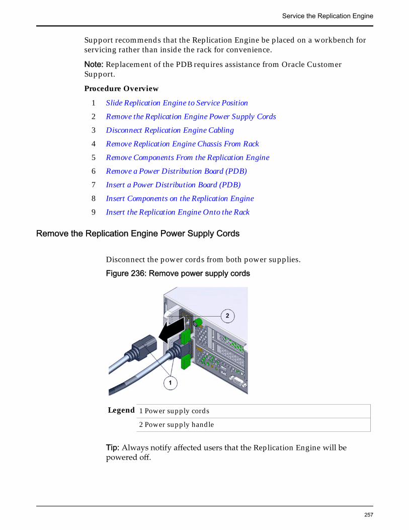
Support recommends that the Replication Engine be placed on a workbench forservicing rather than inside the rack for convenience.
Note: Replacement of the PDB requires assistance from Oracle CustomerSupport.
Procedure Overview
1 Slide Replication Engine to Service Position
2 Remove the Replication Engine Power Supply Cords
3 Disconnect Replication Engine Cabling
4 Remove Replication Engine Chassis From Rack
5 Remove Components From the Replication Engine
6 Remove a Power Distribution Board (PDB)
7 Insert a Power Distribution Board (PDB)
8 Insert Components on the Replication Engine
9 Insert the Replication Engine Onto the Rack
Remove the Replication Engine Power Supply Cords
Disconnect the power cords from both power supplies.
Figure 236: Remove power supply cords
Legend 1 Power supply cords
2 Power supply handle
Tip: Always notify affected users that the Replication Engine will bepowered off.
Service the Replication Engine
257

Slide Replication Engine to Service Position
Squeeze the release buttons on either side of the Replication Engine frontpanel at the same time and slide the Replication Engine chassis forwarduntil the slide rails lock into position. You might have to remove screwslocking the front panel to the rack before the Replication Engine slidesforward.
Caution: Deploy any rack anti-tilt mechanism before releasing the releasebuttons and extending the Replication Engine chassis.
Figure 237: Slide the Replication Engine to service position
Legend 1 Rack
2 Replication Engine chassis
3 Release buttons
Important: Before you slide the Replication Engine chassis out, ensure thatthe cables do not interfere with the movement of the Replication Enginechassis. Although the cable management arm (CMA) is hinged so that youcan extend the Replication Engine chassis, all cables and cords must be outof the way when you service the Replication Engine components.
Service the Replication Engine
258

Disconnect Replication Engine Cabling
Disconnect all data cables from the Replication Engine.
Note: All cables must be disconnected from the Replication Engine andlabeled such that they can be reconnected accurately to the ReplicationEngine after the replacement procedure is complete. Reconnecting cablesto the incorrect position might impact the performance of the ReplicationEngine or result in a complete loss of functionality.
Note: Service the Replication Engine components from the front of theReplication Engine while the Replication Engine is in service position.
Note: Do not lean on or place any weight on the Replication Engine whilethe Replication Engine is in the service position.
Remove Replication Engine Chassis From Rack
The following procedure is optional.
1 From the front of the Replication Engine, press on the slide-rail release tabson both sides at the front of the Replication Engine, and pull theReplication Engine out of the rack until is free of the rack rails.
Important: Oracle recommends not removing the Replication Engine fromthe rails for servicing the components. All components are designed forreplacement and servicing while the Replication Engine chassis is on therails. However, if you must remove the Replication Engine from the rack,disconnect the rear panel Replication Engine cables from the front with theReplication Engine in service position.
Note: A slide-rail release tab is located on each slide-rail of the ReplicationEngine.
2 With the help of a partner or a mechanical lift, place the Replication Engineon an antistatic surface on a workbench.
Remove Components From the Replication Engine
Note: Some components must be removed from the Replication Engine as aprerequisite for access while replacing the failed component.
Note: All components that are removed from the Replication Engine must beplaced on an antistatic surface or ESD qualified mat.
Remove a Power SupplyNote: To replace a power supply, you can access the faulted power supply fromthe back of the Replication Engine module. To access the power supply located in
Service the Replication Engine
259

the bottom slot (PS-1), the CMA clip must be disconnected to enable the powersupply to clear the support arm.
Note: Replacing the power supply does not require you to slide the ReplicationEngine into the extended rack position and can be performed while theReplication Engine is in the rack position.
1 Remove the power supply by grasping the power supply handle andpushing the power supply latch to the left.
Figure 238: Replication Engine power supply latch
Legend 1 Power supply handle 3 Power supply
2 Power supply latch 4 Replication Engine back
Figure 239: Remove power supply
Service the Replication Engine
260

Legend 1 Power supply
2 Power supply compartment
3 Replication Engine
2 If both power supplies must be removed, label the power supplies with theslot numbers from which they are removed.
Note: Removing both power supplies will result in the immediatepowering off of the Replication Engine. Do not pull both power suppliesfrom an active and running Replication Engine.
Note: The power supplies must be reinstalled into the same slots fromwhich they were removed.
3 Pull the power supply out of the chassis and place it on an antistatic mat.
Remove an Air Filter
1 At the front of the Replication Engine chassis, locate the air filter releasetabs.
2 Press the release tabs inwards at the same time to unlock the tabs anddisengage the air filter.
Figure 240: Air filter release tabs
Legend 1 Release tabs 2 Air filter
3 Carefully rotate the top of the air filter outwards and as the release tabsdisengage, lift out the filter.
Service the Replication Engine
261

Figure 241: Remove air filter
4 Set the air filter aside.
Open the Replication Engine Top Cover
1 Fully loosen the two captive thumb screws at the back of the top coverusing the Phillips number 2 screwdriver, if necessary.
Figure 242: Captive thumb screws to remove the top cover
Legend 1 Replication Engine top cover
2 Captive screws
2 Slide the top cover backwards 0.5 inches (13 mm) and lift the top coverstraight up and off the Replication Engine chassis.
Service the Replication Engine
262

Remove a Fan Module
1 Using your thumb and forefinger, grasp the removal tab and gently lift thefan module from the fan compartment.
Figure 243: Remove fan module
Legend 1 Replication Engine chassis
2 Fan compartment
3 Removal tab
4 Fan module
Note: Pulling the green tab from the middle releases the locking tab foreach individual fan.
Note: When removing a fan module, do not rock it back and forth. Rockingthe fan module can cause damage to the motherboard connectors.
2 Set the fan module aside.
Note: The fan compartment might come out when the last fan module isremoved.
Remove the Fan Compartment
Service the Replication Engine
263
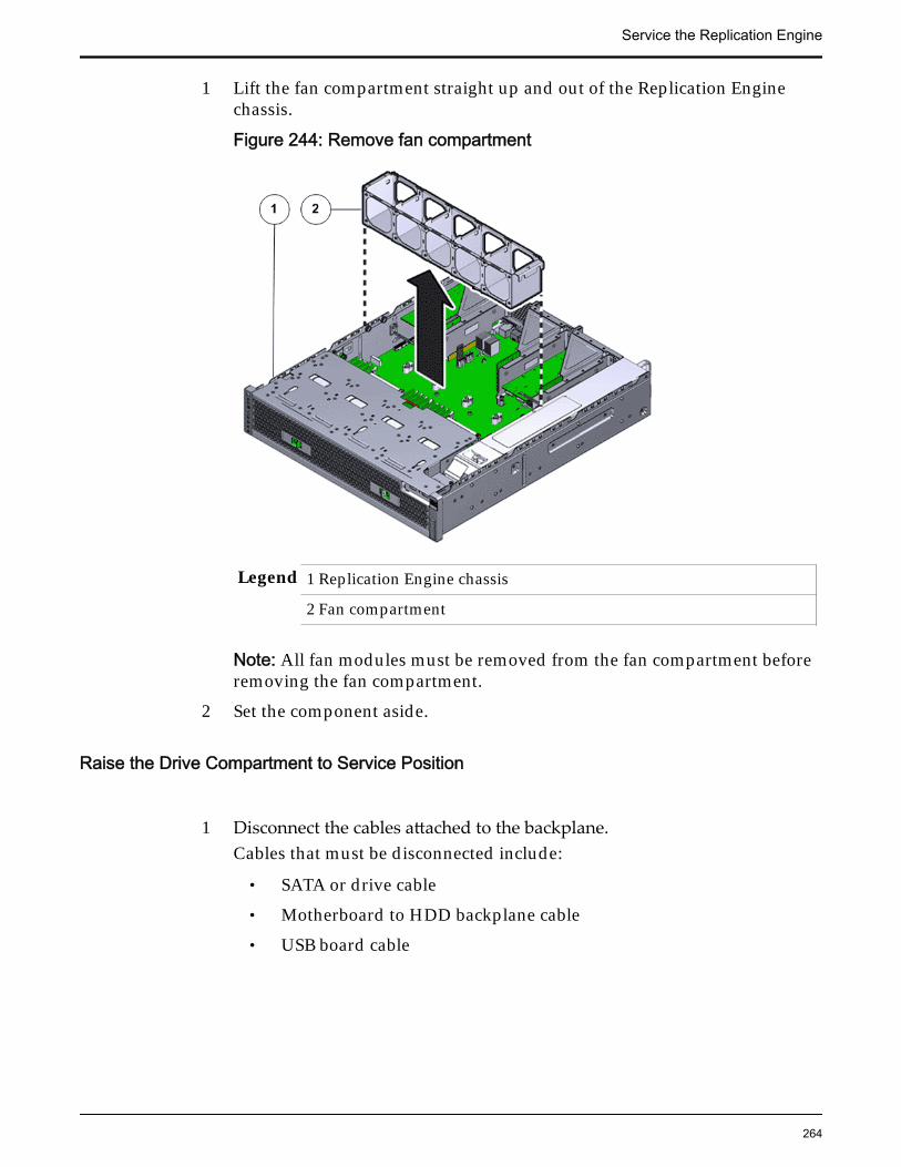
1 Lift the fan compartment straight up and out of the Replication Enginechassis.
Figure 244: Remove fan compartment
Legend 1 Replication Engine chassis
2 Fan compartment
Note: All fan modules must be removed from the fan compartment beforeremoving the fan compartment.
2 Set the component aside.
Raise the Drive Compartment to Service Position
1 Disconnect the cables attached to the backplane.Cables that must be disconnected include:
• SATA or drive cable
• Motherboard to HDD backplane cable
• USB board cable
Service the Replication Engine
264

Figure 245: Cables connected to the backplane
Legend 1 SATA or drive cable
2 NV-DIMM cables
3 Drive compartment
4 Backplane boards
5 Motherboard to HDD backplane cable
Note: The USB board cable is connected to the Replication Engine displaypanel.
Note: All cables attached to the backplane must be disconnected beforeraising the drive compartment. Otherwise, the cables might get damagedor tear due to unnecessary flexure or pull.
Note: Note the location of all the cable connections to the backplane forlater re-connection of the cables after the replacement procedure iscompleted.
Tip: Refer to the service label for more information on rotating the drivecompartment.
2 Disengage the backplane by loosening the four Phillips Number 2 thumbscrews on the four sides of the backplane using a Phillips Number 2screwdriver and rotate the backplane at a 90 degrees angle.
Service the Replication Engine
265

Figure 246: Disengaging the backplane
Legend 1 Thumb screws that secure the backplane
2 Backplane
Note: Use the screwdriver very carefully to avoid damaging the electricalcircuitry inside the Replication Engine.
3 Raise the backplane and drive compartment to the vertical position.
Figure 247: Drive compartment raised
Service the Replication Engine
266

Legend 1 Backplane
2 Drive compartment
3 Replication Engine motherboard
Remove an Air Duct
1 Remove the air duct by loosening the two brackets and the PhillipsNumber 2 thumb screws on both sides of the air duct.
Figure 248: Remove air duct
Legend 1 Screws that secure air duct
2 Air duct
Note: The brackets that secure the air duct are labeled L (left) and R (right).The left bracket slides forward and the right bracket slides back whenfacing the Replication Engine in the service position.
2 Lift up the air duct from the Replication Engine chassis and set it aside.The following figure shows a Replication Engine air duct:
Service the Replication Engine
267

Figure 249: Air duct
Remove a Riser
1 Disconnect any external cables that remain connected to the HBAs in therisers.
Note: Also disconnect any internal cables attached to the HBAs, if that willease removing the HBA.
Tip: Make a note of the positions of all existing cable connections beforeremoving any cables. Replacing HBAs or their cables into the incorrectposition in the riser may result in a loss of performance or functionality.
2 Note the position of the HBAs installed on the riser.
Tip: Make a note of the slot numbers of all existing HBAs before removingany HBAs.
3 Using a Phillips Number 2 screwdriver, loosen the two Phillips Number 2captive screws on either side of the riser that hold the riser to theReplication Engine motherboard.
Note: The riser on the opposite end of the power supply has a latch thatmust be disengaged to remove the riser from the Replication Enginechassis
Service the Replication Engine
268

Figure 250: Captive screws to secure the risers
Legend 1 Riser 3 with latch 3 Riser 1
2 Riser 2 4 Captive screws that secure riser
To remove riser 3, unlock the latch to release the riser from the ReplicationEngine motherboard.
Figure 251: Unlock Riser 3 latch
Service the Replication Engine
269

Legend 1 Riser 3 latch 3 HBA
2 Riser 3
4 Carefully pull the riser straight up and place it aside.
Figure 252: Remove riser
Legend 1 Riser
2 Replication Engine motherboard
Remove Motherboard Cables
1 Gently disconnect the motherboard cable from its connector.
Note: Replacing a motherboard cable might require you to remove somecomponents from the motherboard based on the location of the cable thatyou are replacing. Make sure that you have adequate access to the cableconnectors while replacing the motherboard cable.
2 Set the cable aside on an antistatic mat.
Remove a Power Distribution Board (PDB)1 Lift up the cover over the PDB by pressing the tabs on the cover and set the
cover aside.
Service the Replication Engine
270

Figure 253: Remove PDB cover
Legend 1 PDB cover
2 Power supply duct
3 PDB board
4 Replication Engine motherboard
Note: You must disconnect the PDB flat signal cable and the PSU ductwhen you lift up the PDB cover. The PDB signal cable might look slightlydifferent from the one shown in the graphic.
Figure 254: Disconnect PDB flat cable
Service the Replication Engine
271

Legend 1 PDB flat signal cable that connects the PDB to the motherboard
2 PDB bus bars
3 PDB
4 PDB cage
2 Remove the two Phillips screws that secure the PDB to the PDB cage usinga Phillips Number 2 screwdriver.
Figure 255: Remove PDB circuit board
Legend 1 PDB bus bars
2 PDB circuit board
3 Phillips screws that secure the PDB to the PDB cage
4 PDB cage
3 Lift the PDB assembly up and forward off of the alignment pins gently.
Note: Lifting or bending the motherboard while removing the PDBassembly can permanently damage the motherboard by breaking the CRUsor FRUs on the motherboard and the circuit traces on the motherboard.
4 Remove the PDB assembly and place the PDB assembly on an antistaticmat.
Service the Replication Engine
272

Figure 256: Remove PDB assembly
Legend 1 PDB circuit board
2 PDB cage
Insert a Power Distribution Board (PDB)
1 Unpack the component from its shipping carton.
Note: Place the component on an antistatic mat if it must be set aside forany reason.
2 Position the PDB to where it installs into the chassis.
Service the Replication Engine
273

Figure 257: PDB alignment
Legend 1 PDB circuit board
2 PDB cage
Note: The bus bars are forward and down.
3 Place the bus bars into the channels, and move the PDB rearward anddown onto the alignment pins.
4 Using a Phillips Number 2 screwdriver, loosely insert the four PhillipsNumber 2 screws that secure the PDB assembly onto the motherboard.
Service the Replication Engine
274
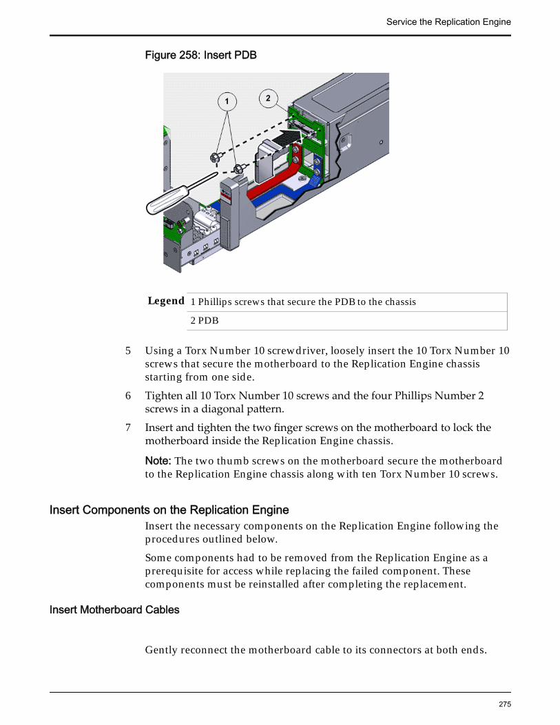
Figure 258: Insert PDB
Legend 1 Phillips screws that secure the PDB to the chassis
2 PDB
5 Using a Torx Number 10 screwdriver, loosely insert the 10 Torx Number 10screws that secure the motherboard to the Replication Engine chassisstarting from one side.
6 Tighten all 10 Torx Number 10 screws and the four Phillips Number 2screws in a diagonal pattern.
7 Insert and tighten the two finger screws on the motherboard to lock themotherboard inside the Replication Engine chassis.
Note: The two thumb screws on the motherboard secure the motherboardto the Replication Engine chassis along with ten Torx Number 10 screws.
Insert Components on the Replication EngineInsert the necessary components on the Replication Engine following theprocedures outlined below.
Some components had to be removed from the Replication Engine as aprerequisite for access while replacing the failed component. Thesecomponents must be reinstalled after completing the replacement.
Insert Motherboard Cables
Gently reconnect the motherboard cable to its connectors at both ends.
Service the Replication Engine
275

Insert a Riser
1 Lower the riser onto the Replication Engine motherboard and press theriser edge connector securely into the socket.
Important: Ensure that any HBAs that must be removed from the failedriser and placed onto the replacement rise are inserted into the same slotson the replacement riser.
Figure 259: Insert riser
Legend 1 Riser
2 Replication Engine motherboard
2 After the riser is seated properly inside the Replication Engine, tighten thetwo captive Phillips screws on both sides of the riser to secure the riser onthe Replication Engine motherboard.
Service the Replication Engine
276

Figure 260: Captive screws to secure risers to the motherboard
Legend 1 Riser 3 with latch 3 Riser 1
2 Riser 2 4 Captive screws
To install riser 3, lock the latch to secure the riser to the Replication Enginemotherboard.
Figure 261: Riser 3 latch locked
Service the Replication Engine
277

Legend 1 Riser 3 latch 3 HBA
2 Riser 3
3 Reconnect any previously removed internal or external cables to any HBAsinstalled in the riser.
4 Repeat the above steps for any additional risers that you are installing.
Insert an Air Duct
Secure the air duct inside the Replication Engine by tightening the twoPhillips Number 2 screws into position.
Note: The brackets that secure the air duct are labeled L (left) and R (right).The left bracket slides forward, the right bracket slides back when facingthe Replication Engine in the service position.
Lower the Drive Compartment1 Rotate the drive compartment and backplane back into position inside the
Replication Engine and ensure that the alignment pins engage.
Note: To confirm that the backplane is locked into position, listen for anaudible click or feel the backplane engage with the Replication Engine.
2 Secure the backplane inside the Replication Engine by inserting the fourPhillips Number 2 thumb screws on the four sides of the backplane andtightening them using a Phillips Number 2 screwdriver.
3 Reconnect all the cables that had been previously disconnected from thebackplane.Cables that must be reconnected include:
• SATA or drive cable
• Motherboard to HDD backplane cable
Service the Replication Engine
278

Figure 262: Reconnect cables to the backplane
Legend 1 SATA or drive cable
2 NV-DIMM cable
3 Drive compartment
4 Backplane boards
5 Motherboard to HDD backplane cable
Insert the Fan Compartment
1 Move any loose cables so that they are against the Replication Enginechassis walls.
2 Align the fan compartment to where it installs into the Replication Enginechassis.
Service the Replication Engine
279
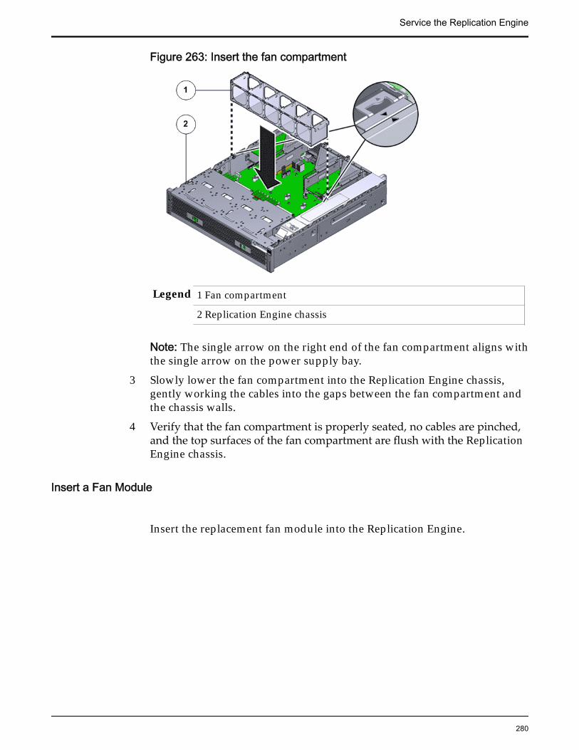
Figure 263: Insert the fan compartment
Legend 1 Fan compartment
2 Replication Engine chassis
Note: The single arrow on the right end of the fan compartment aligns withthe single arrow on the power supply bay.
3 Slowly lower the fan compartment into the Replication Engine chassis,gently working the cables into the gaps between the fan compartment andthe chassis walls.
4 Verify that the fan compartment is properly seated, no cables are pinched,and the top surfaces of the fan compartment are flush with the ReplicationEngine chassis.
Insert a Fan Module
Insert the replacement fan module into the Replication Engine.
Service the Replication Engine
280

Figure 264: Insert fan module
Legend 1 Replication Engine chassis
2 Fan compartment
3 Fan module
Note: Press down on the fan module and apply firm pressure to fully seatthe fan module into the fan compartment. The fan modules are notched toensure that they are installed in the correct orientation.
Note: Repeat for each additional fan module.
Close the Replication Engine Top Cover
Place the top cover of the Replication Engine and tighten the two thumbscrews at the back of the Replication Engine that secure the top cover.
Service the Replication Engine
281

Figure 265: Close Replication Engine top cover
Legend 1 Thumb screws
2 Replication Engine top cover
3 Replication Engine
Insert a Power Supply1 Unpack the component from its shipping carton.
Note: Place the component on an antistatic mat if it must be set aside forany reason.
2 Slide the replacement power supply into the power supply compartment atthe back of the Replication Engine until it is fully seated.
Service the Replication Engine
282

Figure 266: Insert power supply
Legend 1 Power supply
2 Power supply compartment
3 Replication Engine chassis
3 Listen for an audible click or feel the power supply engage to confirm thatthe power supply is properly seated.
Note: Repeat for each power supply. Also, replace the power supplies onlyinto the slots from which they had been removed.
Insert an Air Filter
1 Tilt the top of the air filter slightly towards you and insert the bottom twohooks into the mounting tabs.
Figure 267: Insert air filter
Service the Replication Engine
283

Important: Ensure that nothing interferes with the edges of the air filter andthat the air filter seats properly.
2 Press the top corners of the air filter to engage the top two air filter hookswith the top rail tabs.
3 Press both air filter release tabs until they lock in place.
Insert the Replication Engine Onto the Rack
Insert the Replication Engine into the rack.Inserting the Replication Engine onto the rack includes the following tasks:
1 Lift up the Replication Engine Onto the Rack
2 Slide the Replication Engine back into Rack position
3 Reconnect the Replication Engine cabling and the CMA
4 Power on the Replication Engine
5 Verify the Replication Engine component status
Insert Replication Engine Chassis Onto Rack
With the help of a partner or a mechanical lift, engage the ReplicationEngine with the rack rails.
Caution: Do not use the power supply handles to lift the ReplicationEngine. Using the power supply handles to lift the Replication Engine candamage the power supplies and disrupt electrical power to the ReplicationEngine.
Reconnect Replication Engine Cabling
1 Reconnect all the data cables on the Replication Engine.
Note: Oracle Customer Support recommends labeling all cables connectedto the Replication Engine so that the cables can be reconnected accuratelyto the Replication Engine after the replacement procedure is complete.
2 Reconnect the CMA to the Replication Engine by attaching the release tabon the left and right side of the CMA.
Slide Replication Engine to Rack Position
Slide the Replication Engine back into the rack.
Service the Replication Engine
284

Note: You must release the rail locking mechanism to slide the ReplicationEngine chassis back into the rack.
Service the Replication Engine
285
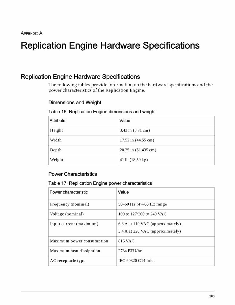
APPENDIX A
Replication Engine Hardware Specifications
Replication Engine Hardware SpecificationsThe following tables provide information on the hardware specifications and thepower characteristics of the Replication Engine.
Dimensions and Weight
Table 16: Replication Engine dimensions and weight
Attribute Value
Height 3.43 in (8.71 cm)
Width 17.52 in (44.55 cm)
Depth 20.25 in (51.435 cm)
Weight 41 lb (18.59 kg)
Power Characteristics
Table 17: Replication Engine power characteristics
Power characteristic Value
Frequency (nominal) 50–60 Hz (47–63 Hz range)
Voltage (nominal) 100 to 127/200 to 240 VAC
Input current (maximum) 6.8 A at 110 VAC (approximately)
3.4 A at 220 VAC (approximately)
Maximum power consumption 816 VAC
Maximum heat dissipation 2784 BTU/hr
AC receptacle type IEC 60320 C14 Inlet
286

IndexAadditional resources 20air filter
how toreplace 87
service procedures 87
Ccable management arm 66cable types
Ethernet cable 56fiber channel (FC) cables 56
cablingEthernet ports 59FC ports 59Replication Engine 59
cabling Replication Engineguidelines 58prerequisites 59
Call-Home 69, 72central processing unit (CPU)
how toreplace 172
service procedures 172complete the installation
supply power 67turn on the Replication Engine 67
component inspectionReplication Engine 34
components 80, 81components, Replication Engine 81configuration options 27–29connect power cords 66contact information 20customer support 20
Ddefault settings
network ports 32DIMM (s)
how toreplace 131
service procedures 131disk backplane
how toreplace 144
service procedures 144documentation
feedback 20related to hardware procedures 20
drive 101drives
how toreplace 101
service procedures 101
Eeducation programs 20Ethernet cables 56Ethernet ports
cabling 59
Ffailed components 81Failed Components
hardware 80fan modules
how toreplace 89
service procedures 89FC configuration using RJ45 connectors 28FC Configuration using SFP or optical connectors 29FC ports
cabling 59feedback, documentation 20fiber channel (FC) cables 56Fiber Channel (FC) configuration using RJ45
connectorsconfiguration options 27–29
Fiber Channel (FC) ports 26Fiber Channel ports 30
Gguidelines
cabling Replication Engine 58
HHardware 81hardware components
replacement conceptsair filter 87central processing unit (CPU) 172DIMM (s) 131disk backplane 144drives 101fan modules 89HBA 117heat sink 160LED alarm assembly 186
287

motherboard 206motherboard cables 244power distribution board (PDB) 255power supplies 96riser board assembly 107
hardware problemshow to
replace central processing unit (CPU) 172replace heat sink 160replace motherboard 206replace power distribution board (PDB) 255
hardware replacement 82HBA
how toreplace 117
service procedures 117HBA cards 24, 27HBAs
supported 24heat sink
how toreplace 160
service procedures 160how to
insert 87, 89, 96, 101, 107, 117, 131, 144, 186, 244remove 87, 89, 96, 101, 107, 117, 131, 144, 186,244route power 66test Call-Home 72verify status
Replication Engine 69using Call-Home 69
how to replacecustomer replaceable units (CRUs) 84how to replace
field replaceable units (FRUs) 84
IILOM port
on the Replication Engine 31insert
air filter 87DIMM (s) 131disk backplane 144drive 101fan module 89HBA 117LED alarm assembly 186motherboard cables 244power supplies 96riser board assembly 107
install HBA cards 27installation procedures
power on the system 67tools, required 34turn system on 67
IP addresshow to set 70
LLED alarm assembly
how toreplace 186
service procedures 186
Mmotherboard
how toreplace 206
service procedures 206motherboard cable kit(s/es)
how toreplace 244
motherboard cableshow to
replace 244location 227service procedures 244type 227
Nnetwork ports
default settings 32Number of HBAs 27
Oon the Replication Engine 26, 30online help 20Oracle documentation 20Oracle Help Center (OHC) 20Oracle Integrated Lights Out Manager 82Oracle Integrated Lights Out Manager (ILOM) 81Oracle MaxRep for SAN
overview 21wiring diagrams 60
Oracle MaxRep Replication Engine 82
Ppart numbers 39PDUs
how topower on components 67
ports 26power cords
connect 66power distribution board (PDB)
how toreplace 255
power supplies
Index
288
how toreplace 96
service procedures 96prerequisites
cabling Replication Engine 59product support 20
Rrack
how toverify rail installation 51
rack-ready 39racks 39rail kits 39rails
how toverify 51
related books 20remote management
using ILOM port 31remove
air filter 87DIMM (s) 131disk backplane 144drive 101fan module 89HBA 117LED alarm assembly 186motherboard cables 244power supplies 96riser board assembly 107
replaceair filter 87central processing unit (CPU) 172DIMM (s) 131disk backplane 144drive 101fan module 89HBA 117heat sink 160LED alarm assembly 186motherboard 206motherboard cable kit 244motherboard cables 244power distribution board (PDB) 255power supplies 96riser board assembly 107
replacement 82replacement concepts
Replication engine 84replication
configuration options 27–29Replication engine
replacement concepts 84Replication Engine
component inspection 34
hardware 81how to
insert 53install CMA 48install rack rails 40install slide rails 43power down 82verify rails 51
installing rails 39number of HBAs 27power cords 66power up 84required tools 34service procedures 82, 84supported HBAs 24
Replication Engine hardware componentshow to
power on 67power up 84
Replication Engine rail kits 39Replication Engine status 69Replication Enginerail kits 39replication engines
how toconfigure ILOM network 71reset default ILOM password 71
Replication protection planshow to
resync 84required tools
Replication Engine 34riser board assembly
how toreplace 107
service procedures 107routing power 66
Ssales information 20SAN replication
overview 21service procedures
air filter 87central processing unit (CPU) 172DIMM (s) 131disk backplane 144drives 101fan modules 89HBA 117heat sink 160LED alarm assembly 186motherboard 206motherboard cables 244power supplies 96Replication engine 84riser board assembly 107
Index
289

tools, required 34set
IP address 70Support portal 20
Ttraining programs 20
Wwiring diagrams
Oracle MaxRep for SAN 60
Index
290