optomized testing campaign and creating onerous …
TRANSCRIPT
1
OPTOMIZED TESTING CAMPAIGN AND CREATING ONEROUS BASELINE DATA FOR A CENTRIFUGAL COMPRESSOR - A PROPOSAL TO MANUFACTURER
Mantosh Bhattacharya Petrofac International UAE
Petrofac Tower 1 Telephone 00971501469853
Abstract This paper proposes an optimized testing agenda for centrifugal compressor with a compact manufacturing and testing schedule. As API mandates to conduct mechanical run tests (MRT) of all compressors of similar deign and geometry, it takes a good amount of time to conduct these tests on OEM test bed particularly if numbers of compressors are large. This paper proposes to conduct only one Full load Full speed (FLFS) test as mechanical run test at vendor works among the full lot of same model and design. The intention of the paper is to classify the criticality of compressors and then deliberate on the extent / type of tests taking account of OEM test bed capability and schedule of delivery of machines and then optimize the test agenda .To supplement the FLFS test, the paper proposes to undertake extensive design audit activities in terms of rotor-dynamics, aerodynamics taking account of case histories of past failures which can raise the confidence level of the end user. Assurance of dimensional repeatability in terms of metrology backed by latest methodology of fault identification of multi-layered manufacturing process with PQM, which can avoid multiple tests of similar machines, may avoid multiple third party inspection at various stages thus saving time. In No load MRT site conditions such as influence of process parameters such as gas pressure / density, foundation dynamics are not replicated. The MRT do not identify the region of incipient surge, effect of aerodynamic cross coupling instability as well. The paper proposes to introduce various instruments and sensors to detect the above instability region for the proposed extensive test .With the rotor-dynamic data taken from the proposed test set up, it shall be easy to further enhance the base line data after site performance test .The same can be used for pre-alarm configuration based on zone wise amplitudes in vibration spectrum which can be very useful for reliability engineer engaged in diagnostic and prognostics. For critical machines located in hostile environment, anomaly detection may be carried out with shape identification of plot / spectra.
Keywords - MRT , Full Load test , optimizarion of schedule, rotor-dynamic data
Introduction - As mandated by API 617(standard for Axial and Centrifugal Compressors and Expander-compressors for Petroleum, Chemical and Gas Industry Services), all centrifugal compressors have to undergo a four hour mechanical run test at full speed.

2
API 617 is not explicit about the pressure, type of gas used as flow medium hence all the tests are conducted either in a partial vacuum or at very low suction pressure using inert gases. During the test , shaft displacement measurements are taken by proximity probes - eddy current sensors mounted orthogonally at same probe tracks. During the test, criteria of direct (overall) shaft vibration are met - √ (12000/N) or 1.0 mil peak to peak whichever is less (while N is the Rotor Speed in RPM). API 617 also requires that the discrete nonsynchronous vibration shall not be more than 20% of maximum allowed value for overall vibration. The standard also requires the frequency range of shaft vibration measurement shall be in the range of 0.25 to the 8 times of the Maximum Continuous Speed. A brief refresher is added as below paragraph before we weigh the real value addition this type test renders .
Conventional Mechanical Run Test -
It is a normal belief that MRT (Mechanical run test) results can surface all possible defects in rotor bearing system as there is no damping of rotor vibration by process gas at pressure. During the test conducted in very low pressure gas mixture, pressure and temperature of lubricating oil for bearings are varied to see the rotor response. The bearing metal temperature, lube oil temperature and pressure, seal oil temperature and pressure, bearing housing vibration, shaft vibration, and power consumption are the parameters that are measured in the mechanical running test. As per API 617, the job bearings, job vibration probes and job seals are used for the mechanical running test.
Fig 1 - Typical screen shot of monitoring screen during compressor MRT
In MRT, shop driver and shop base frames are used with contract / moment simulated couplings Shop verification of unbalance response test on main rotor at the end of four-

3
hour MRT is carried out by some of OEM. This is to validate the calculations carried out to predict 1st critical speed. Unfiltered and filtered displacement amplitudes and the corresponding phase angles are recorded and plotted vs. speed during coast down. Bode plots during coast down are also generated during MRT .It is a common practice that OEM (compressor designers & manufacturers) carry out factory internal test prior to customer (or end user) witnessed test. Normally, compressor performance test (ASME PTC10 type 2) is conducted either before, or after the mechanical running test. If a compressor is first subjected to mechanical running test but fails the performance test, the time, resources, and efforts expended in arranging the mechanical running test would be deemed wasted. From this viewpoint, some users prefer to run performance test first, followed by mechanical running test. The requirements of performance test are also included in API Standard 617.On completion of MRT , the loop is left for cooling and then bearings strip-down , visual check and assembled compressor gas leakage test is carried out . The compressor end seals (contract seals) are kept in the installed condition during assembled compressor gas leakage test.
Fig 2 -Compressor MRT - Project specific base frame not used
The compressor is subjected to soap water bubble test. The soap bubble test is done based on the requirement of the ASME Section V - Article 10 - Leak testing or OEM test procedure. The specific leak test solution is used for the test. The applicable standards for centrifugal compressor testing are: -
• For Mechanical performance - API Standard 617; Centrifugal Compressor for Petroleum, Chemical and Gas Service Industries

4
• For Thermodynamic performance - ASME PTC 10; Performance Test Code on Compressors and Exhausters OR BS- ISO 5389 Turbo compressors Performance Test Code. After performance test, Reynolds Number correction is done in accordance to ICAAMC only after mutual agreement with end user and OEM.
Component checks carried out before MRT (Spin test of compressor) by OEM
1. Centrifugal Compressor Individual Impeller Over speed Test (Spin Test). In this test, the impeller is subjected to the thorough dimensional inspection before the test. The inside diameter (bore), outside diameter, throat are measured and documented. The compressor impeller over-speeding test is performed before rotor assembly. The impeller mounted in the machine in a vacuum chamber (to avoid windage) and then is rotated at the speed of 115% of the MCS for 1 minute. The impeller is subjected to the strong centrifugal force during this 1 minute after over-speed test; a second dimensional inspection is performed and checked against first dimensional inspection. The change in the dimension is inevitable, but the change shall be within the acceptance range. API 617 does not provide acceptance range and refers that to the manufacturer specification. The inspector reviews before and after dimensional inspection reports and check that with manufacturer acceptance criteria and make sure the change in dimension fall within acceptance range after impeller over speed test . In the fourth step, the impeller is subjected to the dye penetration or magnetic particle test to make sure no crack developed during impeller over speeding test
2. High speed balancing / Low speed balancing of assembled rotor using influence coefficient methods In addition to rotor balancing , Rotor stability can be assessed by perturbation tests at balancing machine in particular cases where mass of rotor is comparatively low and OEM has a less fleet record of similar design.
3. Dry gas seal test is carried out at Seal supplier works according to approved procedure.
4. Rotor assembly dimensional check with end float and gap check between rotoric and statoric part is also carried out and verified with API 617 RCV analysis considering highest Amplification factor at 1st critical speed and recorded. The alarm and trip setting of high radial and axial vibration is done accordingly.
In addition to above, multiple checks are carried out by OEM at different stages of manufacturing as per internal test notes or engineering practice. A tight manufacturing tolerance is maintained in such a way that summation of all dimensional errors during manufacturing still lies in acceptance band.
Complete Unit Test is included in API Standard 617 under the section ‘Optional Tests’. Frequently, it is called as string test. Some users stipulate full-speed, full-load / full pressure mechanical running test for compressors while some ask for no-load full speed test of unit. Complete Unit Test with no-load full speed test is like a spin test of complete unit assembled.This type of test cannot detect - torsional lateral coupling, super-synchronous vibration in pinion of speed increaser gear box. Shorter plant commissioning

5
schedule of critical machines in the field is one of the deciding factors to enforce complete unit test of one among the multiples of similar trains. In such situation, end users may want to pay more money upfront for complete unit test than having to spend much more in rectifications at site, if something were to go wrong. Known rotor-dynamic issues or concerns arising from stability analysis of the compressor are validated in full load test. Compressor with special design features such as with multiple side loads, fitted with honeycomb seals, whole pattern seals shunt holes, or swirl brakes may require more exhaustive testing than conventional performance test and mechanical running test. Complete unit test results can be set as bench mark for multiple criteria. If a complete unit test is specified for compressors installed in identical, multiple production trains, it is be carried out on the compressor(s) in only one train.
The question is - Do we achieve a desired outcome of repeated MRT of all centrifugal compressors from a same model number in a testing campaign or a no load complete unit test ?
Based on review of numerous MRT results of such compressors, it is found that critical speed measured are within 3-5% variation with adequate separation margin , 1x compensated shaft displacement at resonant speed do not defer more than 20% and 99.5% of machines meet the criteria of 25.4 um peak-peak vibration. So, the MRT results of all compressors of same model and configuration can be considered as “monotonously” asymptotic. Statistically, the failure history of compressors in MRT is very rare although some of those machines failed to meet acceptance criteria in FLFS test or at site with actual process condition. What we measure in MRT such as bearing pad temperatures , oil consumptions , effect of unbalance ( calculated ) , slow roll run out data for 1x compensation , is measured in FLFS ( Full load Full speed) / FSFP ( Full load Full pressure ) test with more onerous level .We can measure / witness Coupling enclosure windage effects , oil foaming issue, effect of possible extrusion of bundle O-ring inside the casing, sub-synchronous vibration due to stability in FLFS / FSFP test which cannot be measured / witnessed in MRT.
There are many cases of sub synchronous vibration were encountered in compressors due to aerodynamic instability in a particular impeller stage, flow related instability due to incipient surge, stall in diffuser / impeller stall, SSV due to pad instability and effect of cross coupling.

6
Fig 3- Waterfall showing pinion super-synch vibration at particular speed -load range
During some cases high sub synchronous and super synchronous vibration of pinion of speed increaser gear box were also encountered with a turbo compressor unit.
All above incidents were detected either in full speed, full load test at OEM works or at site. Since full load full speed tests were not conducted at OEM works for some compressors these issues surfaced at site and took lot of time to rectify.
Consider there is a fleet of 9 compressors for three sites of same model but have slightly different operating conditions. Time line for the API 617 MRT and PTC 10 tests if conducted as per conventional methods, shall be around 4- 5 months. Time line for preparation of full load test / full load test at test bed shall be around 2-3 months with a higher level of confidence to end user in machine offered by OEM. So, if OEM conducts a full load full speed test, it can give a good vibration base line data and higher level of integrity assurance.
To optimize the testing campaign and creation of onerous base line data a series of road map is proposed for an OEM to consider -

7
Road Map of integrity assurance at design phase
It is prudent to have extensive in house design audits by OEM pertaining to mitigate rotor-dynamic and aerodynamic instabilities and prepare reports. The analysis and report should consider -
• Finite element based rotor-dynamic modelling ( using linear and non-linear parameters / coefficient of bearings and seals wherever applicable ),
• Considering pivot stiffness using best suited software for different designs • Evaluation of loss of interference , • Using API 617 level 2 stability analysis over calculating rotor stability ratios
rather using statistical approach such as Futon -Sood and Donald -Kirk charts , • Ensuring AF( amplification factor ) at 1st critical speed below 8 (using soft
bearings ) , • Exploring use of rub tolerant inter-stage seals , • Squeeze film damper bearings for lightweight compressor rotor, use of Helmholtz
resonator / Low solidity vanes and proper evaluation of such design , • Impeller dynamic modelling and SAFE analysis. • Modified Seenoo and Nishida criterion of critical angle to be incorporated along
with OEM design data to avoid impeller and diffuser stalls.
A quick first hand estimation calculation for stress estimation on impeller can be done as-
σ = {(u squared x ρ} / C where u is impeller peripheral velocity at MCOS (Maximum continuous operating speed), ρ is density of impeller material, σ is actual stress being applied on impeller and C is a constant in order of 160000 based on flow coefficient. MCOS is maximum continuous operating speed.
The calculated stress must be less than 75% of yield strength of material selected for impeller when used in sweet gas service and 65% of yield strength of material selected for impeller used in sour gas service as defined in NACE standard. Impeller dynamic analysis must be carried out to identify the potential resonance of impeller for compressor handling high density gas such as CO2 or having vaned stator / diffuser using SAFE diagram. The combined design experience OEM and on site experience of End-users can be utilized to undertake a joint review of design report.
Road map of integrity assurance at manufacturing phase -
There should be a pre-inspection meeting where it should be communicated and agreed that end user / purchaser quality control / rotating equipment specialist shall visit major sub supplier premises to ensure the ISO norms and imposed standard by compressor OEM are followed during various manufacturing stages.
Component manufacturing checks and reports should be shared with end users and any repairs must be notified for acceptance. End user shall exercise his experience and prudence to accept / reject the repair proposal. In case of any repair comes under rotating
8
components, API RP 687 can serve as a good reference to compare OEM proposed repair procedure.
Every component out of forging place shall have a heat number / unique identification number so that there is no mix up with same components of different origin / purpose. Some of advanced metrology systems are described below which are used in precision manufacturing and can be adopted by OEM subject the manufacturing infra-structure and system.
The in-process measurement control systems can be used in cylindrical grinding machines, for example. OEM uses them to measure small, medium or large work pieces during the production process in the machine. The control units operate with maximum precision, reliability and repetitive accuracy. They continuously check the quality of your components, thereby ensuring that the production results are of consistently high quality.
To ensure process reliability, in-process measurement control systems automatically compensate for any tolerance variations, which can arise, for example, when grinding discs become worn or as a result of temperature fluctuations. In such cases, the in-process control systems monitor the measured values in real time, thus controlling the grinding process continuously until the nominal dimension has been reached. This process helps to minimize part rejection and necessary rework.
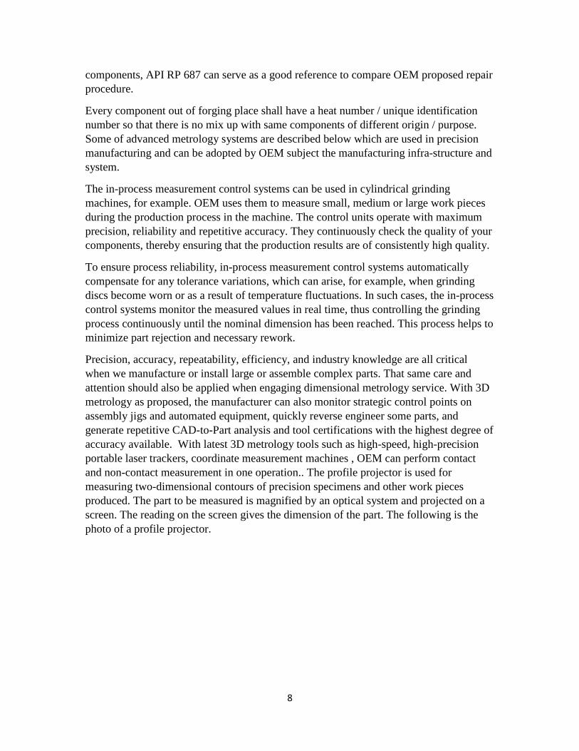
Precision, accuracy, repeatability, efficiency, and industry knowledge are all critical when we manufacture or install large or assemble complex parts. That same care and attention should also be applied when engaging dimensional metrology service. With 3D metrology as proposed, the manufacturer can also monitor strategic control points on assembly jigs and automated equipment, quickly reverse engineer some parts, and generate repetitive CAD-to-Part analysis and tool certifications with the highest degree of accuracy available. With latest 3D metrology tools such as high-speed, high-precision portable laser trackers, coordinate measurement machines , OEM can perform contact and non-contact measurement in one operation.. The profile projector is used for measuring two-dimensional contours of precision specimens and other work pieces produced. The part to be measured is magnified by an optical system and projected on a screen. The reading on the screen gives the dimension of the part. The following is the photo of a profile projector.

9
Fig 4 - Typical Coordinate measurement machine
A coordinate measurement machine (CMM) provides instant measurement results without complicated setup and operating procedures. It combines surface plate, micrometer and Vernier type inspection methods into one easy to use machine. CMM can check the dimensional and geometric accuracy by using probe supported on three mutually perpendicular (X, Y & Z) axes. Each axis has built-in reference standard circuit boards.
Impellers which are most sensitive components in compressor are machined with an aim to achieve high dimensional accuracy and acquire specific performance. However, manufacturing uncertainties result in dimensional deviations causing incompatible operational performance and assembly errors. Process capability limitations of the manufacturer can cause an increase in part rejections, resulting in high production cost. To ensure that a turbo-machine is robust to some of manufacturing uncertainties, impeller can be parameterized and evaluated using a commercial computational fluid dynamics (CFD) solver. A sensitivity analysis can be performed initially to identify the critical geometric parameters which influence the performance mainly. Sensitivity analysis can be followed by the uncertainty propagation and quantification using Monte Carlo simulation. Finally, a robust design optimization can be carried out using a stochastic optimization algorithm leading to a robust impeller design. In engineering, optimization problems are often of this type, when we do not have a mathematical model of the system (which can be too complex) but still want to optimize its behavior by adjusting certain parameters.
Road map of integrity assurance at testing phase-
It is advisable to conduct high speed balancing of rotor and then validate the readings with the coupling hub attached. Over-speed test should conducted with an extra probe mounted in such a way that rotor mode shape plot can be drawn and validated with

10
analysis before it goes to test bed . The balancing machine should have similar type of bearing principal stiffness and damping which is used in contract machine ( Compressor).
A pre-test meeting should be held at OEM test bed so that end user / purchaser are clear about objective and confident that calibrated measurement devices being used. The skid foundation may use choking / clamping devices at various places to enact the effect of epoxy grout under base frame at site condition.
For full load full speed test of compressor, it is imperative to measure all the transient vibration and record the plots and analyze them with help of a certified vibration analyst. Any sub-synchronous vibration component / small hump in spectrum should not be discarded as noisy signal. The plots should be shared with witnessing team at test bed itself. All concerns (genuine and benign) should be addressed with technical professionalism .Dry gas seal primary vent flow and pressure must be monitored continuously as it is one of the tell-tale signs of possible transient rotor bow.
To check the rotor susceptibility to aero dynamic instability such as incipient surge, impeller / diffuser stall, OEM can use various acoustic pulsation detection device / pressure monitor probes / sensors at stage drains as port. The sensors should have high resonance frequency so that the measurement is correct .Dynamic Pressure Monitor with a signal booster is a specialized monitor that monitors the pressure pulsations with a high accuracy even at high temperature.
Fig 5 - Extra sensors and Electromagnetic shaker installed for FLFS extended test

11
Fig 6 –Pressure Fluctuation ΔP across time shaft
The Dynamic Pressure monitor accepts signals via its associated transducer I/O module from dynamic pressure sensors and dynamic pressure charge amplifier. The monitor further conditions these signals into the appropriate measurement units, compares them to user-programmable alarm set points, and generates appropriate alarm signals for communication to the host control system. The measurement can be peak-to-peak dynamic pressure or RMS dynamic pressure. The results can be further cross checked with particular region of vibration spectrum. In some cases, test results had led to modification in return channel / diffuser of compressors at OEM works which could have resulted into enormous delay to mitigate at site.
Fig 7 Vibration spectrum during stall
To validate the robustness of rotor bearing design for any cross coupling forces, a magnetic shaker can be used to generate perturbation from a sweep of speed above slow roll to operating speed during full load full speed test. During the test, the casing vibration also can be measured so that with proper processing of actual shaft vibration in

12
peak- peak is carried out. It is to be noted that lateral vibration analysis report always predict absolute shaft displacement in peak -peak.
After a short shutdown during its FLFS test, the compressor should be subjected to a hot restart. With this test, it can be found if high vibration at critical speed can reach alarm / trip level during start up and does not allow a quick start of machine at site. The high vibration also can be an indication of possible rotor to stator rub. A bode plot and orbit plot (direct and 1x filtered) can be used to check above aspect. The measured value shall be used to calculate RCV (remaining clearance value) and to determine if the threat of rotor to stator rub exists.
Validation of train robustness against torsional instability during FLFS complete unit test - If the system has a VFD as driver and / or a speed increasing gear box suitable device such as strain gauge telemetry , torsiograph shall be used to fix the speed band which can be avoided if out of compressor operating speed map . If they fall in speed map, then a quick and proven design solution should be exercised after joint deliberation with end user and third party specialist
Fig 8 - Waterfall of dynamic torques measured with strain gauge telemetry

13
Road map of integrity assurance during start up and regular operation phase-
Piping alignment, flange management and proper pipe hanger setting is “a must do “to avoid casing distortion which leads to misalignment and high 1x vibration at site . Axial rubs can result from a mis-match in the thermal growth rates between the rotor and casing. During a cold startup, the rotor may expand faster than the more massive casing. A related problem can occur when a slide key on the machine casing hangs up and prevents free movement of the casing during startup or shutdown. The constrained machine casing can deform, displace internal parts, and cause an internal rub.
For all above such reasons, before starting the machine a joint review by end user, site support engineer from OEM should happen and outcomes must be recorded and shared with central engineering team of OEM. For flexible couplings after assembly balancing, the set shall be etched marked for unbalance location to mitigate 1x vibration and canning effect. No safety critical device should be bypassed. Trip multiplier / alarm annunciation should not be used in centrifugal compressor to start the machine unless agreed and requirement is proven at test bed. Suction strainer (temporary) should have high and high- high differential pressure alarm and trip which should be half of value of design pressure of strainer. If clean up run with nitrogen is suggested by OEM then correctly sized orifice and suitable speed band shall be advised by OEM
Before machine is put on forward flow, it is imperative to configure a pre- alarm level for all vibration probes based on test bed data, which can be further modified as the machine sets in after some months of operation. The pre alarm data shall provide an alert to reliability / condition monitoring engineer. The pre alarm can be further refined for individual forcing frequencies.
While the machine is put on forward flow service, compressor performance map is to be revisited (a repeat ASME PTC 10 test is not required) and fine tune to set capacity control and load sharing management. In this work, as built compressor map from PTC 10 performance test conducted at OEM works should be kept as base line data. Testing conducted during commissioning will establish a baseline of actual performance as it gathers the data from those instruments which shall remain in loop. Periodic field tests are often conducted to verify the overall performance and signal changes that may predict mechanical damage, internal fouling, or other deteriorating conditions. If periodic tests by operating personnel are not possible then online performance system can be installed based on compressor configuration, criticality of compressor in terms of process upsets.
It has now been realized by most of end users, that merely having vibration monitoring system does ensure the high system availability. Hence in addition, diagnostic tools and software are installed in a dedicated computer which is manned by a reliability / condition monitoring system.
Machinery condition based monitoring (CBM), fault and failure classification and remaining useful life are challenges that are gaining much interest by industrial communities. Study reports from various sectors of academia and industry shows the
14
expected improvements of using automatic or semi-automatic systems for condition monitoring, where a significant improvement on maintenance costs and total productivity can be realized .The operator must first determine whether an anomaly has occurred, then separate faults from failures and isolate the problems to be studied and/or modelled.
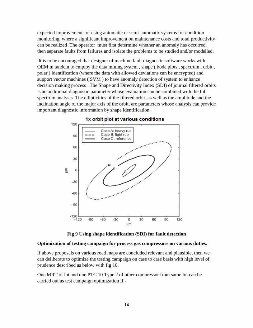
It is to be encouraged that designer of machine fault diagnostic software works with OEM in tandem to employ the data mining system , shape ( bode plots , spectrum , orbit , polar ) identification (where the data with allowed deviations can be encrypted) and support vector machines ( SVM ) to have anomaly detection of system to enhance decision making process . The Shape and Directivity Index (SDI) of journal filtered orbits is an additional diagnostic parameter whose evaluation can be combined with the full spectrum analysis. The ellipticities of the filtered orbit, as well as the amplitude and the inclination angle of the major axis of the orbit, are parameters whose analysis can provide important diagnostic information by shape identification.
Fig 9 Using shape identification (SDI) for fault detection
Optimization of testing campaign for process gas compressors on various duties.
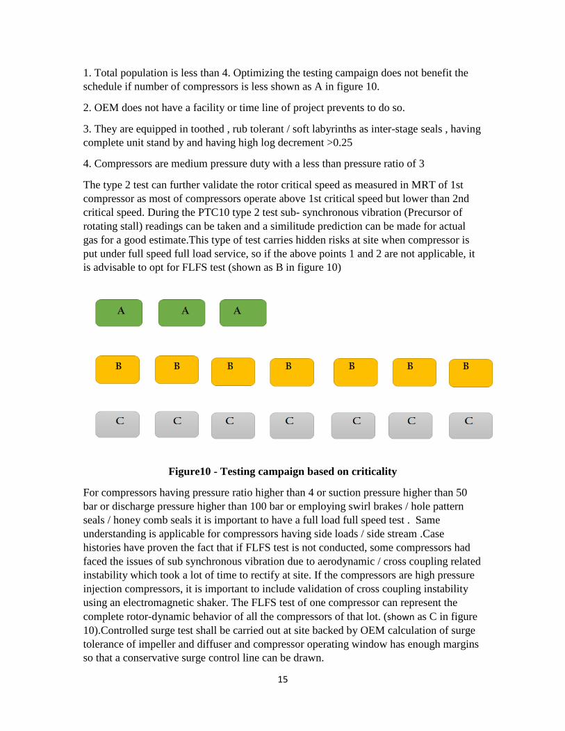
If above proposals on various road maps are concluded relevant and plausible, then we can deliberate to optimize the testing campaign on case to case basis with high level of prudence described as below with fig 10.
One MRT of lot and one PTC 10 Type 2 of other compressor from same lot can be carried out as test campaign optimization if -
15
1. Total population is less than 4. Optimizing the testing campaign does not benefit the schedule if number of compressors is less shown as A in figure 10.
2. OEM does not have a facility or time line of project prevents to do so.
3. They are equipped in toothed , rub tolerant / soft labyrinths as inter-stage seals , having complete unit stand by and having high log decrement >0.25
4. Compressors are medium pressure duty with a less than pressure ratio of 3
The type 2 test can further validate the rotor critical speed as measured in MRT of 1st compressor as most of compressors operate above 1st critical speed but lower than 2nd critical speed. During the PTC10 type 2 test sub- synchronous vibration (Precursor of rotating stall) readings can be taken and a similitude prediction can be made for actual gas for a good estimate.This type of test carries hidden risks at site when compressor is put under full speed full load service, so if the above points 1 and 2 are not applicable, it is advisable to opt for FLFS test (shown as B in figure 10)
Figure10 - Testing campaign based on criticality
For compressors having pressure ratio higher than 4 or suction pressure higher than 50 bar or discharge pressure higher than 100 bar or employing swirl brakes / hole pattern seals / honey comb seals it is important to have a full load full speed test . Same understanding is applicable for compressors having side loads / side stream .Case histories have proven the fact that if FLFS test is not conducted, some compressors had faced the issues of sub synchronous vibration due to aerodynamic / cross coupling related instability which took a lot of time to rectify at site. If the compressors are high pressure injection compressors, it is important to include validation of cross coupling instability using an electromagnetic shaker. The FLFS test of one compressor can represent the complete rotor-dynamic behavior of all the compressors of that lot. (shown as C in figure 10).Controlled surge test shall be carried out at site backed by OEM calculation of surge tolerance of impeller and diffuser and compressor operating window has enough margins so that a conservative surge control line can be drawn.

16
Before mandating the FLFS complete unit test we must weigh the ability of the OEM centralized shop to conduct such test. Logistics of transporting gear, turbines / heavy duty electric motors and VFD panel to the test shop must be analyzed before placement of offer. It should be understood does the project schedule allow for additional time duration for transportation, assembly of string and dismantling and packaging?
Once the above facts are jointly understood and risk and rewards are weighed , the complete unit FLFS test at OEM works can be shifted to site activity as “site machinery performance test “.
The above proposals does not absolve OEM from performing their internal test to build up the confidence level of fleet and such tests can be offered for remote witness of end user specialist. The duration of test need not to have a four hour steady state run but all relevant transient data can be captured and analyzed. For fast track project, a modular designed unit may be considered by OEM which may save time in installation and that time can be utilized for extensive site testing.
References
[1]Vibrational Diagnostics of Rotating Machinery - Agnes Muszynska IJRM 1995 [2]Sleeve Bearing Diagnostics Using Proximity Probes - www.vibration.org/Presentation [3]Transient Speed Vibration Analysis -Insights into Machinery Behavior -Stanley R. Bognatz Presented at: Vibration Institute Piedmont Chapter Meeting 2007 [4]Experience in empirical criteria for rotating stall in rotating stall in radial vaned diffuser- Fulton & Blair -Proceedings of 24th Turbo-machinery symposium TAMU [5]Recent Experiences in Full Load Full Pressure Shop Testing of a High Pressure Gas Injection Centrifugal Compressor," Proceedings of the 23rd Turbo-machinery Symposium, TAMU [6]ASME PTC 10 modified test for mechanical test assessment for centrifugal compressors - M. Miranda & Noronha - Proceedings of the 26th Turbo-machinery Symposium, TAMU [6]Back to Basics – Rubbing or Not? - Richard Thomas, Vibration Institute Piedmont Chapter 2015 SETPOINT™ [7]A Novel method to detect surge - Mantosh Bhattacharya Gas Machinery Council paper 2013. [8] Reliable Rotor Dynamic Design of High-Pressure Compressors Based on Test Rig Data- By Wagner- Journal of Engineering for Gas Turbines and Power | Volume 123 | Issue 4 | [9] Start-up Issue with Centrifugal Compressors after Short Shutdown and Mitigation to Enhance Reliability and Availability- Mantosh Bhattacharya Proceedings of MFPT 2016 Dayton Ohio [10]Layered manufacturing - a Tutorial by Sara Mcmains

17
[11]Diagnostic Significance of Orbit Shape Analysis and its Application to Improve Machine Fault Detection - N. Bachschmid, P. Pennacchi and A. Vania -Politechnic of Milan [12]Data Modeling for fault detection - HM Jainsch Huntsville Alabama
[13]Fault detection and prediction to application of rotating machinery - Thesis desertion by Gary.R.Halligan 2009 Missouri University of science and technology [14]Condition monitoring fault diagnosis and prognostics of industrial equipment by Enrico Zio -Polytechnic of Milan [15]Machine Fault Signature analysis - by P Jayaswal - IJRM 2008 [16]Predicting time to failure of industrial machine based on temporal data mining - Thesis desertion by Jean Nakamura 2007 University of Washington [17]Early detection of rotating stall phenomenon in centrifugal compressor by means of ASME PTC 1 type 2 test - L. Baldassarre et al -Proceedings of the 41st Turbomachinery Symposium TAMU [18]Rotating component modal analysis and resonance-by F Kushner -Proceedings of the 23rd Turbomachinery Symposium TAMU [19]How To Justify Equipment Improvements Using Life Cycle Cost and Reliability Principles - Paul Barringer Bibilography
[1]API 617 Standard for Axial and Centrifugal Compressors and Expander-compressors for Petroleum, Chemical and Gas Industry Services 8th edition [2]Forsthoffer's Best Practice Handbook for Rotating Machinery -By William E. Forsthoffer [3]Forsthoffer's Rotating Equipment Handbooks: v. 3: Compressors by William E. Forsthoffer [4]Principles for alarm system design - Norwegian Petroleum Directorate. [5]Applying Condition Monitoring to Various Machinery- Application Techniques ALLEN BRADLEY [6]Vibration Spectrum Analysis: A Practical Approach - by Steve Goldman