optoelectronic system design final projectecee.colorado.edu/~ecen5616/webmaterial/satcom.pdf ·...
TRANSCRIPT

Optoelectronic System Design
Final Project
Max ColiceOptoelectronic Computing Systems Center
Department of Electrical & Computer EngineeringUniversity of Colorado
Boulder, CO [email protected]
(303) 735-3348
December 12, 2003
1

1 Problem Description
As described in earlier documents, this system will transmit a signal from a ground-based stationto a satellite in geosynchronous orbit. The satellite will retroreflect the beam, now modulated at alower frequency. The high level block diagram in Figure 1 describes system operation.
ModulatedLaser
Trans./Rec.Multiplexing
Scheme
Data Out
Air & SpaceRetroreflector
w/Detector& Modulator
Detector
Data In Data In
Electronics
Data Out
BackgroundNoise
Ground-basedTelescope
Space-basedTelescope
Figure 1: High level system block diagram. The dashed box indicates the portion of interest.
This document contains a detailed design analysis of the ground-based and space-based telescopesand of the retroreflector, as indicated by Figure 1. It will also provide external specifications forall detectors, modulators and the laser itself.
2 Draft Specifications
This system must transmit a beam modulated at MHz rates from the Earth’s surface to asatellite orbiting the Earth at an altitude of approximately 42,000 km (geosynchronous orbit). Thereceived signal must be sufficiently strong so as to achieve a Signal-to-Noise Ratio (SNR) of ≥10dB. The system will use an optical carrier at wavelength of 1.55 µm to take advantage of theatmospheric absorption window in the infrared. The satellite-based receiver will retroreflect thebeam to its point of origin. The retroreflected beam will be modulated at kHz rates.
The system should be portable and mounted such that the user can achieve pointing stability tobetter than 10 murad. The gound-based portion of the system should be operable over a reasonabletemperature range (0 C to 50 C). In addition, the retroreflected beam intensity levels should besufficiently high to achieve a ≥10 dB SNR and low enough to be eye safe.
3 Design Selection
As the design selection was discussed in great detail in a previous document (Project Specifi-cations II), it will receive only modest attention below. Direct detection was chosen over coherentdetection for reasons of simplicity. Coherent detection has an inherent gain advantage, but it isextremely difficult to phase-lock two sources separated by 42,000 km. Direct detection does not giveany gain, but it also does not require exceptional frequency stability or a complicated phase-lockingscheme.
The retroreflection scheme was also chosen in order to simplify the device design. It eliminatesthe need for a laser on the satellite, although at a cost in power - no more than the received power
1

may be used for retroreflection. This is essentially a stare-stare design; the user points the upwardbeam in the appropriate direction (possibly determined using GPS triangulation), and the satellitereflects light back down to the user. No complicated scanning mechanisms are required. This sortof system will be lighter, easier to package and longer lived as it has no moving parts.
4 Design
As the ground-based and space-based telescopes are widely separated, they will be treated asdecoupled systems for the purposes of analysis. The design process will begin with a determinationof the laser power level necessary for acheivement of the 10 dB SNR goal. The telescopes andmultiplexing scheme necessary for the Earth-based transmitter/receiver will then be addressed indetail.
4.1 SNR Determination
The received optical power for both telescopes can be determined by means of simple Gaussianoptics. Each telescope will be assumed to emit a collimated beam. As the range between telescopesis extremely large, it is not unreasonable to treat the beams impinging on the telescopes as planewaves (i.e., parallel rays). Picking the Earth-based and space-based telescope apertures fixes thecollimated beam waists and allows us to calculate the received beam waists as follows. We canstart by determining the Rayleigh range, z0,
z0 =πw2
0
λ(1)
where w0 is the radius of the beam waist and λ is the wavelength. The beam radius at somelocation z can be written as
w = w0
√1 +
(z
z0
)2
. (2)
If z À z0, the beam radius may be approximated as w = λz/πw0.We can next determine the irradiance, E, at z by dividing the optical power contained within
this beam radius, Poptical, by the area determined by the beam radius. As we know the wavelengthof the incident light, we can convert this power into photon flux, φ, through the telescope aperture:
φ =λ
hc
Poptical
πw2πr2 (3)
where h is Planck’s constant, c is the speed of light in vacuum and r is the radius of either thespace-based or the Earth-based telescope aperture (depending on the beam direction). The photonflux generates a mean photocurrent, i, at the detector, which can be written as
i = qηφ. (4)
η is the detector quantum efficiency and q is the electric charge. The SNR is simply the ratio ofthe power due to this mean photocurrent to the power due to noise sources,
SNR =i2
σ2shot + σ2
thermal + i2background
. (5)
2

This analysis considers the effects of shot noise, σ2shot, thermal noise, σ2
thermal and noise due tosunlight reflected off the Earth and other stellar bodies. The variances may be written as
σ2thermal = 4kBTB (6)σ2
shot = 2qiB, (7)
where B is the receiver bandwidth and T is the receiver temperature. The optical power due toreflected sunlight can be written as
Pbackground = HbackgroundΩfovAreceiverBfilter, (8)
where Hbackground is the radiance, Ωfov is the solid acceptance angle of the receiver, Areceiver is thereceiver area and Bfilter is the spectral bandwidth of the receiver. The solid angle field of view maybe approximated as (π/4) × (θrec)2; θrec is the angular acceptance of the receiver.1 This opticalpower must be converted to an electrical current, as shown above in Equations 3 and 4.
SNRs and electrical power levels for both the space-based and Earth-based receivers are plottedover a range of laser optical powers in Figures 2 and 3. All values used in the calculation are listedin the Appendix A. The IDL program used to generate these plots is also included at the end ofthis report.
Figure 2: SNR and electrical power levels for the space-based receiver
The space-based receiver SNR reaches 10 dB at a laser power of less than 1 mW, while theEarth-based receiver SNR hits 10 dB at a laser power of roughly 100 mW. These power levels arewell within the reach of modern technology. Note that the space-based receiver is shot noise-limitedat 104 mW and the the Earth-based receiver reaches the shot noise limit at a laser power of < 108
mW.The signal power levels are still fairly low. However, MHz bandwidth Lock-In amplifiers possess
dynamic reserves of ge100 dB, and may be suitable for use with the Earth-based receiver. Pream-plification will definitely be necessary. We will specifiy a minimum laser power level of 1 W (easilyobtainable with today’s technology). Further analysis is beyond the scope of this document.
3

Figure 3: SNR and electrical power levels for the Earth-based receiver
4.2 Earth-based Telescope
The Earth-based telescope must expand the laser’s output to a diameter of 10 cm to meet ourspecifications, requiring 100X magnification for a laser output diameter of 1 mm. In addition,it must contain some sort of multiplexing mechanism so that it can separate the retroreflected,Earth-going beam from the transmitted, space-going beam.
4.2.1 Polarization Multiplexing
Polarization multiplexing is relatively simple, requires no moving components and can be easilyimplemented as the beam will necessarily be reflected at the other end of the link. Laser outputsare usually linearly polarized, although note that an additional polarization element may be neededto further improve the purity of the laser output polarization state. The beam can therefore beconverted to circular polarization by means of a λ/4 plate, as illustrated in Figure 4. The beam isthen expanded using a telescope. The waveplate is placed in the path of the smaller beam, as thewaveplate’s cost will increase as its size increases. The retroreflected beam will have the orthogonalcircular polarization (the polarization will be flipped upon reflection), and will be converted tothe orthogonal linear polarization by the λ/4 plate. The two beams can then be separated bya polarizing beamsplitter; these devices have extinction ratios ranging from 30 dB for thin filmdevices to ≥ 45 dB for crystal optic devices.
4.2.2 Thin Lens Design
In the thin lens approximation, the telescope consists of two lenses separated by the sum oftheir focal lengths. The telescope’s magnification is given by the ratio of their focal lengths,MEarth = −f2/f1. We have taken the laser’s output to be perfectly collimated; this is reasonableat this level of approximation. Note that Figure 4 includes an aperture stop at the focal planeof the lenses. As both the space-going and Earth-going beams should be collimated and directednormally to the lens surfaces, a spatial filter may be used to reject light entering the telescope froman angle. The aperture spot should be no larger than the larger of the minimum spot sizes of thetwo lenses. If the lenses have matched numerical apertures (NAs), then their spot sizes will beidentical. Minimizing the spot size will improve the system’s ability to reject stray light. However,
4

PolarizationStates
f1 f2
f1
f2
/4λ
Detector
Space-going Beam
Earth-going Beam
PolarizingBeamsplitter
ApertureStop
PolarizationStates
ModulatedLaser
Data In
Data Out
Spectral Filter
Figure 4: Schematic representation of the Earth-based telescope
the lenses with larger NAs tend to have worse aberration performance, increasing the resolvablespot size past the diffraction limit. We will compromise by selecting moderately fast lenses for usein the Earth-based telescope. Spectral filtering also reduces noise levels.
4.2.3 ZEMAX Design
It is very difficult to achieve diffraction-limited 100X magnification with only 2 lenses, as theprimary lens must be somewhat aggressive and the secondary must be long focal length. As wewould like to achieve good beam quality with short total length ( 0.5 m), it becomes easier to usea set of 10X Galilean telescopes in series. Galilean telescopes possess no internal focus, therebyprecluding the spatial filtering scheme described above. However, another pair of Fourier transformlenses inserted between the 10X telescopes may be used to implement this scheme. A baffle mayalso be used to limit the telescope field of view.
ZEMAX was used to create the Earth-based telescope design. The second 10X telescope wascreated first by using an entrance pupil diameter of 1 cm and a pair of custom singlets. A paraxiallens was used to focus the telescope’s output to the image plane. Optimization was performed usingthe default merit function in conjunction with an additional constraint: the height of the beamimpinging on the paraxial lens was forced to 5 cm (the output beam radius). The lens separationwas fixed at 500 mm. Once this optimization was completed, the first 10X telescope was introducedand the entrance pupil diameter was stopped down to 1 mm. A similar optimization routine wasrun to set the first telescope’s lens parameters, etc. Further results, including a layout, are includedin Appendix B. The ZEMAX Lens Data Editor window is shown below in Figure 5. The systemachieves good performance in a total lenght of 575 mm.
4.3 Space-based Telescope
As stated above, the space-based and Earth-based telescopes are separated by such a largedistance that they can be treated as decoupled systems. The space-based telescope will see parallelrays impinging on its first surface.
5

Figure 5: Earth-based telescope ZEMAX Lens Data Editor window
4.3.1 Functional Design
The space-based telescope is functionally the same as the Earth-based telescope; as shown inFigure 6, it consists of a beam collapser that sends its output to a retroreflecting prism. Themagnification is given by Mspace = −f4/f3. A pinhole located at the interelement focal planeserves to limit the receiver’s angular bandwidth, thereby eliminating additional background lightand improving the SNR.
PolarizationStates
f3 f4
f3
f4ApertureStop
Retroreflector w/Detector & Modulator
Data In
Data Out
Earth-goingBeam
Space-goingBeam
Figure 6: Schematic representation of the space-based telescope
The desired angular bandwidth will determine the minimum spot size and pinhole size. Thespace-going beam’s the angular deviation will be less than 10 µrad for a waist of w0 = 5 cm. Wecan determine the minimum aperture radius, rspace, necessary for achieving this angular resolutionby applying the Rayleigh resolution limit. Recall that the diffraction limited spot size radius isgiven by
ρ = 0.61λf
rspace. (9)
Applying simple trigonometry allows us to find rspace = 9.46 cm. We have chosen rspace = 5 m, asindicated in Table 1 to improve light collection efficiency, and easily satisfy this limit.
6

The retroreflecting scheme relies on some sort of combination detector/modulator, which couldtake one of several forms. It could be a detector array located intelligently on a quarter-wavepush-pull modulator. Alternatively, it could take the form of a quantum well device, such as thatproposed by Gilbreath et al.2 We will specify that its receive bandwidth be 1 MHz and that itstransmit bandwidth be 1 kHz. Note that the SNR calculation performed above did not take intoaccount loss due to photodetection. However, it is reasonable to suggest the 50% of the light isabsorbed and the other 50% is reflected. This would uniformly depress SNR values by 3 dB.
4.3.2 Thin Membrane Mirrors
It is not practical to build 10 m diameter lens for use in space. Solid mirrors of the same diameteralso exceed size and weight limits imposed by modern rockets - the Hubble Space Telescope hasa main mirror diameter of only 2.4 m.3 However, it has been proposed that thin film membranescould be used to construct large mirrors in space.4 Such membrane mirrors would consist of a thin,reflective membrane, such as mylar or a variant thereof, stretched across a support structure. Theywould have low densities and could be folded, making it practical to launch mirrors with muchlarger diameters than those built using conventional techniques.
The membrane thickness must be controlled to within 0.1 µm in order to meet minimum re-quirements for imaging optics; this is not an unreasonable goal, as membranes with a thicknessripple of ±1µm over lengths of 2 m were available commercially as of 2000.5 Adaptive curvaturecould be induced by means of electrostatic pressure.4 This technology could easily allow us toincrease the aperture size to our current target of 10 m.
4.3.3 Cat’s Eye Retroreflectors
Cat’s-eye retroreflectors offer several advantages over lens/mirror and corner cube retroreflec-tors. We have already determined that we don’t wish to launch large lens into space. Hollowcorner cube reflectors typically consist of a minimum of three plane mirrors arranged in a three-fold rotationally symmetric fashion. We would probably need to demagnify the incident beam inorder to use a hollow corner cube. Large solid corner cubes (i.e. prisms) are too heavy to liftinto orbit. Cat’s-eye retroreflectors can be fabricated from two curved mirrors, with the secondarysitting at the focus of the primary. This greatly simplifies the optical design.6 In addition, themodulator/detector can be placed at the beam focus, thereby reducing the size of the device.7
Bear and Marjaniemi propose using a parabolic primary mirror in conjunction with a sphericalsecondary mirror with a power roughly twice that of the primary.6 As before, ZEMAX providesa convenient way to optimize the system design. In this case, an f/5 parabolic mirror of 10 mdiameter was placed in the path of an axial beam of the same diameter. ZEMAX’s default meritfunction was used to optimize the mirror’s curvature and placement with respect to the imageplane. Next, a small spherical mirror was placed at the image plane, and the rays were redirectedoff of the primary mirror onto a paraxial lens. Note that the secondary mirror also serves as aspatial filter; beams outside the angular bandwidth of the system will be focused to points offthe mirror’s surface. Circular obscurations were placed in the path of the incoming and outgoingbeams to compensate for the present of the spherical secondary. The spherical mirror curvature wasthen optimized to provide diffraction-limited performance using the default merit function. TheZEMAX Lens Data Editor window is shown in Figure 7. Please refer to Appendix C for systemlayout information and perfomance plots.
Note that the two mirrors are separated by a distance greater than 200 m. A single satellite ofsuch size would have to be constructed in orbit. However, the two mirrors could be located separatespacecraft in concentric orbits.
7
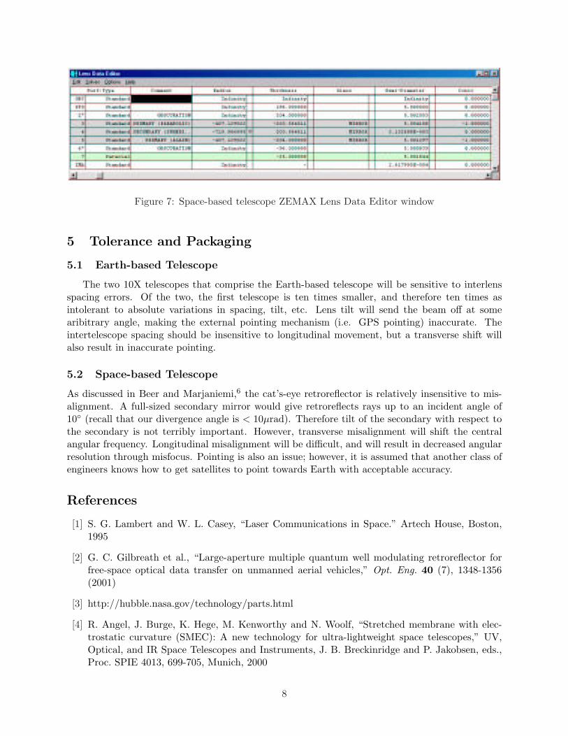
Figure 7: Space-based telescope ZEMAX Lens Data Editor window
5 Tolerance and Packaging
5.1 Earth-based Telescope
The two 10X telescopes that comprise the Earth-based telescope will be sensitive to interlensspacing errors. Of the two, the first telescope is ten times smaller, and therefore ten times asintolerant to absolute variations in spacing, tilt, etc. Lens tilt will send the beam off at somearibitrary angle, making the external pointing mechanism (i.e. GPS pointing) inaccurate. Theintertelescope spacing should be insensitive to longitudinal movement, but a transverse shift willalso result in inaccurate pointing.
5.2 Space-based Telescope
As discussed in Beer and Marjaniemi,6 the cat’s-eye retroreflector is relatively insensitive to mis-alignment. A full-sized secondary mirror would give retroreflects rays up to an incident angle of10 (recall that our divergence angle is < 10µrad). Therefore tilt of the secondary with respect tothe secondary is not terribly important. However, transverse misalignment will shift the centralangular frequency. Longitudinal misalignment will be difficult, and will result in decreased angularresolution through misfocus. Pointing is also an issue; however, it is assumed that another class ofengineers knows how to get satellites to point towards Earth with acceptable accuracy.
References
[1] S. G. Lambert and W. L. Casey, “Laser Communications in Space.” Artech House, Boston,1995
[2] G. C. Gilbreath et al., “Large-aperture multiple quantum well modulating retroreflector forfree-space optical data transfer on unmanned aerial vehicles,” Opt. Eng. 40 (7), 1348-1356(2001)
[3] http://hubble.nasa.gov/technology/parts.html
[4] R. Angel, J. Burge, K. Hege, M. Kenworthy and N. Woolf, “Stretched membrane with elec-trostatic curvature (SMEC): A new technology for ultra-lightweight space telescopes,” UV,Optical, and IR Space Telescopes and Instruments, J. B. Breckinridge and P. Jakobsen, eds.,Proc. SPIE 4013, 699-705, Munich, 2000
8

[5] B. Stamper, R. Angel, J. Burge, and N. Woolf, “Flat Membrane Mirrors for Space Telescopes,”Imaging Technology and Telescopes, J. Breckinridge, ed., Proc. SPIE 4013, 2000
[6] R. Beer and D. Marjaniemi, “Wavefronts and Construction Tolerances for a Cat’s-Eye Retrore-flector,” Appl. Opt. 5 (7), 1191-1197 (1966).
[7] M. L. Biermann, W. S. Rabinovich, R. Mahon and G. C. Gilbreath, “Design and analysis of adiffraction-limited cat’s-eye retroreflector,” Opt. Eng. 41 (7), 1655-1660 (2002).
9

A SNR Calculation Parameters
Table 1: Space-going Beam Parameters
Parameter ValueGeosynchronous Orbital Distance, z 42,000 km
Operating Wavelength, λ 1.55 µmLaser Output Radius, rlaser 0.5 mm
Transmit Aperture Radius, w0 5 cmRayleigh range, z0 5067.1 m
Beam Radius in Space, w 414.4 mReceive Aperture Radius, rspace 0.5 m
Angular Deviation 9.86 µradDetector Temperature, Tspace 10 KDetector Bandwidth, Bspace 1 MHz
Spectral Filter Bandwidth, Bfilter 1.0 nmStellar Radiance, Hbackground 210 W/m2/Sr/µm
Table 2: Earth-going Beam Parameters
Parameter ValueTransmit Aperture Radius, w0 5 m
Rayleigh Range, z0 5.0671× 10⁷mBeam Radius on Earth, w 6.494 m
Receive Aperture Radius, rEarth 0.05 mAngular Deviation 0.356 µrad
Detector Temperature, TEarth 300 KDetector Bandwidth, BEarth 1 kHz
10

B Earth Telescope Design
Figure 8: 3D Layout
Figure 9: Optical Path Difference Figure 10: Ray Fan
Figure 11: Diffraction Encircled Energy Figure 12: Spot Diagram
11

C Space Telescope Design
Figure 13: 3D Layout
Figure 14: Optical Path Difference Figure 15: Ray Fan
Figure 16: Diffraction Encircled Energy Figure 17: Spot Diagram
12