option card for lon star coupler rer 111 slcm · pdf file4 option card for lon star coupler...
TRANSCRIPT

Option Card for Lon Star Coupler RER 111SLCMTechnical Reference Manual


Option Card for Lon Star Coupler RER 111Technical Reference Manual
SLCMIssued: 19.9.1998 Version: C/6.6.2005
We reserve the right to change data without prior notice.
1MRS 750985-MUM
Contents:1. Introduction ...............................................................................52. Applications ...............................................................................63. Functions ...................................................................................7
3.1. General .........................................................................................73.2. Synchronization procedures ..........................................................73.3. Synchronization method performance ..........................................8
4. Mechanical and electrical design ............................................94.1. Mechanical structure .....................................................................9
5. Interfaces .................................................................................105.1. General .......................................................................................105.2. GPS or other time reference interface ........................................10
5.2.1. Signal specification ..........................................................115.2.2. Pulse signal input .............................................................11
5.3. Fibre optic interface .....................................................................125.3.1. Fibre optic interfaces of SLCMFO ....................................13
5.4. Service switch .............................................................................13
6. Installation, configuration and programming .......................146.1. Mechanical installation ................................................................146.2. LON node installation (setting the node address) .......................146.3. Configuration of the network variables (binding) .........................156.4. Configuration of function mode ...................................................20
6.4.1. Jumper settings of SLCM .................................................206.4.2. DIP-switch settings of SLCMFO ......................................226.4.3. Linking alternatives of second/minute pulse ....................226.4.4. Sync. mode setting via LON ............................................25
7. Reference time and time zone parameter via LON ..............277.1. Reference time ............................................................................277.2. Example of system divided into subnets and how to configure it 28
7.2.1. Jumper settings of option cards .......................................297.2.2. Configuring the system by using the
LON Network Tool (LNT) .................................................307.3. SLCM operation in redundant mode ...........................................34
7.3.1. Take-over .........................................................................347.4. Time zone parameter ..................................................................35
8. Technical data .........................................................................36
3

1MRS 750985-MUMOption Card for Lon Star Coupler RER 111
Technical Reference Manual
SLCM
9. Maintenance and service ....................................................... 379.1. LEDs of the SLCM ...................................................................... 37
9.1.1. Fibre optic receiver LED .................................................. 379.1.2. RS232 LED ...................................................................... 379.1.3. Service LED ..................................................................... 379.1.4. Pulse LED ........................................................................ 37
9.2. LEDs of the SLCMFO ................................................................. 379.2.1. Fibre optic receiver LED of serial interface ...................... 379.2.2. Fibre optic receiver LED of pulse interface ...................... 379.2.3. Service LED ..................................................................... 379.2.4. Pulse LED ........................................................................ 37
9.3. Resetting factory defaults ........................................................... 379.3.1. Service and spare parts ................................................... 38
10.Ordering information ............................................................. 39APPENDIX A: Synchronization procedures ............................. 40APPENDIX B: Configuring the GPS clock device .................... 45
Revision history
Date Revision Author Description10.9.1998 A O. Ala-Penttilä Original version30.11.1999 B1 M. Kiikkala Update version (Q4/99)29.12.1999 B2 M. Kiikkala Update version (Q4/99)07.03.2000 B3 M. Kiikkala References to SMA-transceiver option
removed
Echelon, LON, LonBuilder, LonManager, LonTalk, LonWorks, Neuron and 3150 are U.S. registered trademarks of Echelon Corporation. LonLink, LonMark, LonSupport, LonUsers, LonMaker and 3120 are trademarks of Echelon Corporation
4

1MRS 750985-MUM Option Card for Lon Star Coupler RER 111
Technical Reference Manual
SLCM
1. Introduction
The LON Clock Master option card is intended to be used in the LON Star Coupler RER 111.
There are two alternative types of LON Clock Master:
1. SLCM (Star Coupler LON Clock Master with RS232/TTL interface to clock reference device)
2. SLCMFO (Star Coupler LON Clock Master with Fibre Optic interface to clock reference device)
The LON Clock Master option card is a LON node that interfaces to a clock reference device and performs time synchronization on LON. There are five separate time synchronization methods for different types of bay level devices and for different accuracy requirements.
Both SLCM and SLCMFO have the same application software.
Later in this document The LON Clock Master is in general referred as SLCM.
5

1MRS 750985-MUMOption Card for Lon Star Coupler RER 111
Technical Reference Manual
SLCM
2. Applications
In the RER 111 unit, the SLCM option card provides a connection from a time reference device to the LONWORKS network. The SLCM option card includes an internal clock and an application program which uses the internal clock to generate various synchronization messages and signals in order to synchronize other devices on the LONWORKS network.
RER 111
LON Clock Master
Fiber optic connectionto bay level devices
GPS or other clockreference device
Connection to higherlevel devices e.g.monitoring equipment
slcm_1
Fig. 2.-1 System structure. The SLCM inserted in the LON Star Coupler (RER 111).
6

1MRS 750985-MUM Option Card for Lon Star Coupler RER 111
Technical Reference Manual
SLCM
3. Functions
3.1. GeneralThe SLCM option card connects to the LONWORKS network trough the open collector bus on the RER 111 unit�s mother board.
When the SLCM is connected to a clock reference device and the time pulse and time messages have been received, the internal clock can be adjusted to UTC time or local time. If only UTC time is available from the time reference device and local time is needed, the appropriate time zone parameter must be set by the operator via the LON. The same applies to daylight-saving shifts.
Note! The internal clock of the SLCM is adjusted to the clock reference device time (GPS clock) only if the GPS clock has connection to the satellite and it is synchronized with it (i.e. the GPS clock has valid time). If the GPS clock does not have valid time when the SLCM is powered up or reset, the SLCM will not start sending synchronization messages to the LON network until it receives a valid time from GPS clock.
The SLCM option card also contains a service switch. Pressing of this switch generates a service pin message. This service pin message is used by the network management device (e.g. higher level processors, PC, etc.) to install and configure the SLCM option card. The service pin message is sent to the LONWORKS network.
The SLCM option card also contains a service LED. This LED is blinking when the SLCM is in the unconfigured state. After configuration of the SLCM option card, the LED is off. The configuration and the use of the SLCM option card require a host device, for example, a PC.
The SLCM option card also sends information about the clock reference device status to the LONWORKS network. The content of clock status message is based on information of the Meinberg Standard Time String Interface Protocol. Therefore, the full advantage of the clock status is taken only if a clock reference device with the Meinberg Standard Time String Interface Protocol is used. However, regardless of the interface protocol used, the clock status message is always sent to the LON whether the SLCM has a connection to the external clock or not.
The clock status message is always sent after SLCM option card reset or if the state of the connection to the external clock changes. If the SLCM receives clock reference time via LON, then the clock status is not used.
3.2. Synchronization proceduresThe SLCM option card can use five different methods of synchronizing other devices on the network. The synchronization messages are sent via the LON. After receiving synchronization messages, the other devices on the network can adjust their internal clocks to the master�s time.
NOTE! It is important that synchronization messages are sent as priority messages (see table 6.3.-2) and that collision detection is not used in the SLCM.
For more information about synchronization procedures, see appendix A.
7

1MRS 750985-MUMOption Card for Lon Star Coupler RER 111
Technical Reference Manual
SLCM
3.3. Synchronization method performance
Table 3.3.-1 Accuracy of synchronization methods.Method AccuracySNVT_time_stampnv_timenv_clock_warning & nv_clockVATS with bit pattern detectionVATS pulse based
10...100 ms10...100 ms1...5 ms100 µs100 µs
Note! Since these accuracies are valid only when the second pulse is used an accurate second pulse is a required. When a minute pulse is used these accuracies are not guaranteed.
8

1MRS 750985-MUM Option Card for Lon Star Coupler RER 111
Technical Reference Manual
SLCM
4. Mechanical and electrical design
4.1. Mechanical structure
The LON Clock Master option card is built on a printed circuit board (PCB) of size 100 mm x 160 mm. The size of the front plate is 116.4 mm x 19.8 mm.
RS232interface
service pin
fibreoptic TX
fibreoptic RX
service LED
fibre optic LED
RS232 LEDpulse LED
ServicePin
SLCM-C-MM08
24B
FOC
RS
232
ServiceLed
RS232
Pulse
Tx/Po
Rx/Pi
slcm_2
Fig. 4.1.-1 Mechanical structure of the SLCM option card.
serialinterface
fibre optic LED
fibre optic LED
pulse LED
service LED
service pin
TX
RX
pulseinterface
Pi
Po
SLCMFO-C-MM
Tx
Pi
Rx
Po
FOC
FOC
0933
B
ServicePin
ServiceLed
Pulse
Ser
ial
slcm 3
Fig. 4.1.-2 Mechanical structure of the SLCMFO option card.
9

1MRS 750985-MUMOption Card for Lon Star Coupler RER 111
Technical Reference Manual
SLCM
5. Interfaces
5.1. GeneralThe SLCM option card has four separate interfaces:
- a 64-pin E1 card connector for the connection to the mother board of the RER 111 unit.
- a fibre optic transceiver pair- a 9-pin D-type female connector for RS232 interface to clock reference and
second / minute pulse- service switch.
The SLCMFO option card has four separate interfaces:
- a 64-pin E1 card connector for the connection to the mother board of the RER 111 unit.
- a fibre optic transceiver pair for serial interface to clock reference - a fibre optic transceiver pair for second / minute pulse input and output- service switch.
5.2. GPS or other time reference interfaceThe RS232 interface is used to connect to a GPS or an other clock reference device. Data from the RS232 interface includes time information in serial data format based on ASCII characters.
The SLCM supports the following ASCII-based communication protocols:
1. TAIP (Trimble ASCII Interface Protocol)2. Meinberg Standard Time String Interface Protocol
Other information about RS232:
- data transfer rate: 4800 bit/s- parity check: NO- data bits: 8- stop bits: 1
The RS232 receiver is provided with its own LED, which flashes when a message is being received.
10

1MRS 750985-MUM Option Card for Lon Star Coupler RER 111
Technical Reference Manual
SLCM
5.2.1. Signal specificationThe RS232 interface has the design of a 9-pin D-type female connector. This connector is wired as a 3-wire interface and intended to be used for the connection to a GPS or another reference time source.
Table 5.2.1-1 The pin designations for the D-type connectorPin Signal Description Signal levels Direction123456789
TxDRxD
GND
Data I/OData I/O
Signal ground
Pulse highpulse low
RS232RS232
-
TTLTTL (accepts open collector drive)
from SLCMto SLCM
to SLCMto SLCM
Communication cables for the SLCM option card have to be separately ordered.
The RS232 communication cable has to be a shielded cable. The length of the serial communication cable is limited to max. 0.5 m
It is recommended to connect the shield to earth in one end of the cable. Depending on the specific case and the surroundings, the cable may, however, need more than one earth connection. In such a case the other earth connections should be made through a capacitor.
The protective shield should be connected to the casing of the D-type connector, which has to be made of a conductive material. The connector of the option card is earthed to the case of the RER 111 unit.
The figure below illustrates the connection of the protective shield to the cable connector.
Protective shield
Conductive casing sslta_4
Fig. 5.2.1.-1 Cable protective shield connection.
On the SLCMFO option card, the serial interface to the clock reference device is implemented using fibre optic transceiver pair, which is always of ST-type. There are no options.
5.2.2. Pulse signal inputThe SLCM card can take advantage of the accuracy of a GPS system only if the GPS pulse output is connected. The pulse input of the SLCM card is integrated into the same D-type connector as the RS232. The pulse input is a TTL-level signal. Pins 8 and 9 are reserved for this purpose. These pulses share the signal ground (PIN 5) with the RS232 bus. Pin 8 is used for triggering on a high going transition (active
11

1MRS 750985-MUMOption Card for Lon Star Coupler RER 111
Technical Reference Manual
SLCM
high pulse) and pin 9 for triggering on a low going transition (active low pulse). The one to be selected depends on the clock reference device used. See jumper configuration instructions in chapter 6.4.
RS232 interface ofSLCM option card
RS232 interface of GPS orother reference time source
PIN2, TxD
PIN3, RxDRxD
TxD
PIN5, signal groundPIN9, pulse input pulse output
RS232RS232TTL or open collectoroutput
slcm_5
Fig. 5.2.2.-1 Pulse connection, active low pulse
RS232 interface ofSLCM option card
RS232 interface of GPS orother reference time source
PIN2, TxD
PIN3, RxD
RxD
TxD
PIN5, signal ground
PIN8, pulse input pulse output
RS232RS232
TTL
slcm_6
Fig. 5.2.2.-2 Pulse connection, active high pulse.
The SLCMFO option card has a fibre optic receiver connection for pulse signal input and a fibre optic transmitter for pulse signal output. These pulse interface connector are always of ST-type.
5.3. Fibre optic interfaceThe SLCM option card is equipped with a single fibre optic transceiver pair, available with two different fibre optic interfaces:
- ST-type glass fibre optic transceiver- snap-in-type plastic fibre optic transceiver
These interfaces are not interchangeable and the desired type should be specified by the user in the order, see chapter 10.0.
12

1MRS 750985-MUM Option Card for Lon Star Coupler RER 111
Technical Reference Manual
SLCM
The SLCM option card also has a LED for the fibre optic receiver. This LED flashes when a message is being received.
The fibre optic connection is jumper configurable for pulse input/output operation (the second/minute pulse can be linked from one SLCM to another) or LON network connection. In the case of pulse input/output operation the only connection to the LON network is the open-collector bus connection.
Note! If a fibre optic interface is used for the LON network connection, then the open-collector bus must be disconnected (jumper S2 in the left position, see figure 6.4.1.-1).
For more information regarding the fibre optic cables and the fibre optic connection of the option cards, refer to the RER 111 manual 1MRS750104-MUM, chapter 6.2.
5.3.1. Fibre optic interfaces of SLCMFOIn the SLCMFO option card the serial interface to a clock reference device is implemented by using a fibre optic transceiver pair. The serial interface has its own fibre optic LED, which flashes when a message is being received. See figure 4.1.-2 for more details.
The SLCMFO option card has a fibre optic receiver connection for pulse signal input and a fibre optic transmitter for pulse signal output. The pulse input has two LEDs � a fibre optic LED and a pulse LED, which are both flashing when a pulse is being received. See figure 4.1.-2 for details.
The fibre optic connectors of the SLMCFO are always of ST-type � there are no options.
The SLCMFO option card has no fibre optic connection to the LON network. There is only a fixed open-collector bus connection to the LON network, i.e. there is no jumper configuration.
5.4. Service switchThe service switch is used to produce a service-pin message. This message can be used by the network management device (e.g. higher level processors, a PC, etc.) to install and configure the SLCM option card. When this switch is pressed and released, the SLCM generates a service pin message. This service pin message is sent to the LONWORKS network.
13

1MRS 750985-MUMOption Card for Lon Star Coupler RER 111
Technical Reference Manual
SLCM
6. Installation, configuration and programming
6.1. Mechanical installationThe SLCM option card is designed to be installed in any of the 9 option card slots of the RER 111 unit.
To install the SLCM option card in the RER 111 unit:
1 Remove the strain screws on the blank plate or the front plate of the option card installed.
2 Lift off the blank plate or pull the required option card out of the casing.
3 Replace the old option card with a new one (the circuit board component side facing away from the power supply).
4 Push the option card into the unit until the front plate is flush with the rack.
5 Tighten the option card or the blank plate to the case with the strain screws.
Notice! Do not touch the fibre optic transceiver. Do not remove dust shields from transceivers not in use.
U1aux U2aux
SERVICE
SERVICE PIN
1
2
8
5
6
3
7
10
11
9
12
4
SLCM Option Card
slcm_7
Fig. 6.1.-1 Installation of SLCM option card in the RER 111 unit.
6.2. LON node installation (setting the node address)When Neuron 3150 chips are shipped from the manufacturer they are assigned a unique, 6-byte identifier (Neuron ID). Each LON node has a service pin. When the service pin is pressed the Neuron chip transmits a network management message "Service Pin Message" containing this Neuron ID. This information may then be used by a network management device to install the node (give the node its logical node address).
The normal node installation procedure is as follows:
1 Start the "Install Node" command of the device responsible for the network management functions (usually the "master" node). You will be requested to press the service pin on the node to be installed.
2 Press the Service Pin of the SLCM card.
14

1MRS 750985-MUM Option Card for Lon Star Coupler RER 111
Technical Reference Manual
SLCM
3 When the network manager node receives the "Service Pin Message", it will set the address of Clock Master node.
The node address is stored in the Neuron chip's internal EEPROM memory (in the domain table) and usually also in the node list of the network manager node.
6.3. Configuration of the network variables (binding)During the configuration, the network variables of one LON Clock Master are logically connected (bound) to network variables in other LON nodes.
In LonTalk protocol terminology, an output network variable is a variable which is sent to the LON from a node and input network variable is a variable which is received by the node.
During binding, the output network variables of the LON Clock Master are connected to the input network variables in other nodes. The input network variables of the LON Clock Master are bound to output network variables in other nodes.
The connections between network variables are done with the help of the network variable configuration table and address table. The network variable configuration table includes the network variable selector values, which are used as system-wide addresses of the network variables. The address table of a node contains the addresses of all the other nodes to which the node is going to send messages. If messages are sent to a group of nodes or if they are broadcast to the network then the address table also contains group address and broadcast address definitions.
Table 6.3.-1 Addressing of network output variables of SLCM.Index Address
01
Subnet broadcastDomain broadcast
Network variable configuration tableThe network variable configuration table contains a 3-byte entry for each network variable. The table can be updated and read using network management commands. The device responsible for network management updates the network variable configuration table during binding of the network variables.
Network variables of LON Clock MasterTables 6.3.-2�6.3.-8 represent the network variable configuration for the SLCM. If a selector is given in the Index & sel column of tables, it is not allowed to change the selector. If no selector is given, the user can give a selector value which is not already used in the LON network, in which the SLCM operates.
15

1MRS 750985-MUMOption Card for Lon Star Coupler RER 111
Technical Reference Manual
SLCM
Table 6.3.-2 Network variables for sending synchronization messages, broadcast every second unless otherwise stated.
Index & sel
Direction & Name Format Description Address
Index Priority
02FF5
Output nv_time_stamp
SNVT_time_stamp Sent immediately after second pulse, accuracy 10...100 ms
0 Yes
12FFE
Output nv_clock_warning
Unsigned shortNV type 254
Contains time interval (30...100 ms) between warning and the actual time messages (VATS- time �messages or NV_clock)
0 Yes
22FFF
Output nv_clock
NV_clockNV type 255
Absolute time with compensation of propagation delay, accuracy 1...5 ms
0 Yes
32FF4
Output nv_sync_pulse
SNVT_state Pulse of fixed length inserted in the preamble, precedes nvo_pulse_time
0 Yes
42FF3
Output nv_pulse_time
NV_time_syncNV type 248
Absolute time of sync. Event detection of Clock Master, sent after nv_sync_pulse, accuracy better than 100 µs
0 Yes
52FF2
Output nv_pattern_time
NV_time_syncNV type 248
Absolute time of sync. Event detection of Clock Master,sent after expl. bit pattern message, accuracy better than 100 µs
0 Yes
132FF7
Output nv_time
NV_timeNV type 249
Sent when full minute elapses, accuracy 10�100 ms
0 Yes
162FF1
Output nv_master_time
NV_time_syncNV type 248
Ref. time to other SLCMs, sent once a minute. Used only when SLCM is in master mode.
1 No
Table 6.3.-3 Network variables for configurationIndex & sel Direction & Name Format Description Address Index
92FF0
Inputnv_sync_mode
SNVT_state Lsb includes synchronization methods used and msb is reserved for GPS protocols
15
10 Inputnv_warn_interval
SNVT_count Time interval between transmission of nv_warning and VATS time messages or NV_clock. Permitted range 30�100. Default 30 ms.
15
11 Inputnv_delay_comp
SNVT_count Used in a warning and a clock-based method, contains transmission delay compensation for adjustment of NV_clock before transmission, given in 100s of microseconds. Permitted range 0�6400. Default = 45 (4500 µs).
15
Note! Values of these network variables are retained over a reset.
16

1MRS 750985-MUM Option Card for Lon Star Coupler RER 111
Technical Reference Manual
SLCM
Table 6.3.-4 Network variables for diagnosticsIndex & sel
Direction & Name Format Description Address
Index Priority
7 Outputnv_invalid_ref
SNVT_lev_disc Sent when the validity of time is changed; ST_OFF (0) = valid ST_LOW (1) = no ref. time after reset ST_MED (2) = no second pulse received during the last 5 seconds or one missing minute pulse
1 No
8 Outputnv_clock_sync_alarm
SNVT_alarm Sent when the validity of time is changed.Contents of alarm_type field:AL_NO_CONDITION (0) = valid AL_ALM_CONDITION (1) = no ref. time after resetAL_TOT_SVC_ALM (2) = lost time synchronization pulse
1 No
15 Outputnv_self_test_result
SNVT_lev_disc For hardware testing. The test is made every 5 minutes.0 = Device OK1 = external counter not running. VATS times not sent.
1 No
Table 6.3.-5 Network variables for reception of reference time value:Index & sel Direction & name Format Description Address Index
62FF1
Inputnv_ref_time
NV_time_syncNV type 248
For receiving reference time from LON. 15
12 Inputnv_time_zone
SNVT_count Changing of time zone. The msb (bit) is the sign (1 = minus, 0 = plus), the rest of the msB (Byte) is for hours. The lsB is for minutes. Note! The value of this network variable is retained over a reset.
15
14 Inputnv_daylight_save
SNVT_lev_disc Changing winter/summer time (1 = daylight-saving time, 0 = standard time)Note! The value of this network variable is retained over a reset.
15
17

1MRS 750985-MUMOption Card for Lon Star Coupler RER 111
Technical Reference Manual
SLCM
Table 6.3.-6 Network variables for GPS diagnosticsIndex & sel
Direction & name Format Description Address
Index Priority
17 Outputnv_clock_status_1
SNVT_state An active SLCM sends whenever the state of reference time device changes and take over situations.
1 No
18 Inputnv_clock_status_1
SNVT_state Redundant SLCM receives status data from an active SLCM. Note selector same as nv_clock_status_1 with index 17.
15
19 Outputnv_clock_status_2
SNVT_state A redundant SLCM sends whenever the state of reference time device changes.
1 No
Table 6.3.-7 Network variable for activating redundant SLCMIndex & sel Direction & Name Format Description Address
Index Priority
202FF0
Output nv_take_over
SNVT_state Sent whenever a redundant SLCM becomes active and an active SLCM needs to be deactivated.Note that selector same as nv_sync_mode
0 No
Table 6.3.-8 Network variables for a redundant SLCM for receiving time messages from an active SLCM.Index & sel Direction & Name Format Description Address Index
212FF5
Input nv_time_stamp
SNVT_time_stamp See Table 6.3.-2 15
222FFF
Input nv_clock
NV_clockNV type 255
See Table 6.3.-2 15
232FF3
Input nv_pulse_time
NV_time_syncNV type 248
See Table 6.3.-2 15
242FF2
Input nv_pattern_time
NV_time_syncNV type 248
See Table 6.3.-2 15
252FF7
Input nv_time
NV_timeNV type 249
See Table 6.3.-2 15
18

1MRS 750985-MUM Option Card for Lon Star Coupler RER 111
Technical Reference Manual
SLCM
NV6
nv_ref_timeNV type 248
NV10
nv_warn_intervalSNVT_count
NV22
nv_clockNV type 255
NV12
nv_time_zoneSNVT_count
NV24
nv_pattern_timeNV type 248
NV 0
nv_time_stampSNVT_time_stampNV
1nv_clock_warningNV type 254
NV 2
nv_clockNV type 255
NV 4
nv_pulse_timeNV type 248
NV 7
nv_invalid_refSNVT_lev_disc
NV13
nv_timeNV type 249
NV16
nv_master_timeNV type 248
NV 3
nv_sync_pulseSNVT_state
NV 5
nv_pattern_timeNV type 248
NV 8
nv_clock_sync_alarmSNVT_alarm
NV15
nv_self_test_resultSNVT_lev_disc
S
L
C
M
NV17
nv_clock_status_1SNVT_state
NV19
nv_clock_status_2SNVT_state
NV20
nv_take_overSNVT_state
NV9
nv_sync_modeSNVT_state
NV11
nv_delay_compSNVT_count
NV14
nv_daylight_saveSNVT_lev_disc
NV21
nv_time_stampSNVT_time_stamp
NV23
nv_pulse_timeNV type 248
NV18
nv_clock_status_1SNVT_state
slcm 8
NV25
nv_timeNV type 249
Fig. 6.3.-1 Input and output network variables of the SLCM.
19

1MRS 750985-MUMOption Card for Lon Star Coupler RER 111
Technical Reference Manual
SLCM
Table 6.3.-9 Contents of nv_clock_status Binary weight Name Description
0 (LSB)
CLOCK_ALIVE 0 = No connection to external clock1 = Connection OK.
1 SYNCHRONIZED 0 = External clock not synchronized after last start-up
1 = External clock at least once synchronized2 FREE_RUNNING 0 = External clock synchronized with its source �
GPS locked1 = External clock running free without
synchronization � GPS not locked3 DST 0 = Standard time (winter time) in use
1 = Daylight-saving time (summer time) in use 4 DST_WARNING 0 = No DST change within the next hour
1 = DST change coming within an hour5 LEAP_SECOND_WARNING 0 = No leap second insertion or withdrawal within
the next hour1 = Leap second insertion or withdrawal within the
next hour6 ACCURACY_DEGRADED 0 = Accuracy within specification
1 = Full accuracy cannot be guaranteed7 <not defined>8
9-15 NODE_NUMBER This message is from a node with this node number (0�127)
6.4. Configuration of function mode
6.4.1. Jumper settings of SLCM The following jumpers can be found on the SLCM board:
S2
S3
J1J3J4
J6J5
slcm_9
Fig. 6.4.1.-1 Jumpers of SLCM.
20

1MRS 750985-MUM Option Card for Lon Star Coupler RER 111
Technical Reference Manual
SLCM
Jumper S2 Determines whether the SLCM option card is connected to the open collector bus of the RER 111 unit or not:
- connected = right position- not connected = left position
Jumper group S3 Jumper group S3 is used to select the second/minute pulse source (D-type connector or fibre optic interface) and the clock pulse type (active HIGH/active LOW). The default settings of the jumpers are illustrated in figure 6.4.1.-1.
The fibre optic connection of SLCM has three function modes: normal mode with LON (1), pulse transmitter mode (2) and pulse forwarder mode (3). The jumper settings for these modes are presented in figure 6.4.1.-2.
S3
J1J3J4
J6J5
Mode 1Normal
S3
J1J3J4
J6J5
S3
J1J3J4
J6J5
Mode 2Pulse transmitter
S3
J1J3J4
J6J5
S3
J1J3J4
J6J5
Mode 3Pulse forwarder
Active LOW pulse
Active HIGH pulse
Active LOW pulse
Active HIGH pulse
slcm_10
Fig. 6.4.1.-2 Default settings of jumper group S3.
Normal mode is used when the second/minute pulse and the reference time from a GPS are received through the D-type connector of the SLCM card. In normal mode, the fibre optic connection can be used to connect the SLCM to the LON network, but then the SLCM must be disconnected from the open collector bus of the RER 111 mother board. See chapter 6.4.3 for more information.
The pulse transmitter mode is used when the second/minute pulse and the reference time from a GPS are received through the D-type connector of the SLCM card and the second/minute pulse is forwarded via optical fibres, e.g. to another SLCM which is not located in the same RER 111 Star Coupler. See chapters 6.4.3 and 7.2 for more information.
The pulse forwarder mode is used when the second/minute pulse is linked from one SLCM to another via optical fibres. See chapters 6.4.3 and 7.2 for more information.
In the pulse transmitter mode or forwarder mode, the LON network connection is not, of course, available through the SLCM�s fibre optic connectors.
21

1MRS 750985-MUMOption Card for Lon Star Coupler RER 111
Technical Reference Manual
SLCM
6.4.2. DIP-switch settings of SLCMFO
S3
1 3 42
O N
slcm_11
Fig. 6.4.2.-1 DIP-switches of SLCMFO.
The DIP-switch group S3 is used to select the function modes of the serial input/output and pulse input/output. See table 6.4.2.-1 for settings.
Table 6.4.2-1 DIP-switch selections of SLCMFOSwitch Target Position Function
1 Serial in ON LIGHT ON during line idle time. OFF LIGHT OFF during line idle time.
2 Serial out ON LIGHT ON during line idle time.OFF LIGHT OFF during line idle time.
3 Pulse in ON Triggering at the start of the pulse.OFF Triggering at the end of the pulse.
4 Pulse out ON LIGHT ON when pulse is being sent.OFF LIGHT OFF when pulse is being sent.
NOTE! LIGHT ON/LIGHT OFF refers to the fibre optic cable, not to the LEDs on the SLCMFO card.
By default all switches are in position ON. (Reference clock device: Meinberg GPS Clock with fibre optic connection.)
6.4.3. Linking alternatives of second/minute pulseThe following figure illustrates alternatives for linking the second/minute pulse from one SLCM to another. Note that the function modes mentioned below are intended for the SLCM with a D-type clock reference device connection.
- the topmost alternatives show a situation where the SLCM cards (or SLCMFO cards) are located in separate RER 111 Star Couplers. In the linking alternative on the right-hand side, the SLCM connected to the GPS is in the pulse transmitter mode. The other two SLCMs are in the pulse forwarder mode. Also see examples in figure 7.1.-1.
- the most underneath alternative shows a situation where the SLCM cards are located in the same RER 111 LON Star Coupler. All the SLCM cards are in the
22

1MRS 750985-MUM Option Card for Lon Star Coupler RER 111
Technical Reference Manual
SLCM
normal mode and the two SLCM cards to the right are disconnected from the open collector bus. Also see figure 6.4.3.2. which illustrates a system where the SLCM cards are in the normal mode.
Tx
Rx
SLCM
Tx
Rx
SLCMSLCMFO
Rx
Pi
Po
SLCMFO
Rx
Pi
Po
Tx
Rx
SLCMSLCMFO
Rx
Pi
Po
Tx
GPSGPS
RS232-FOpulse-FO
pulse-FO
pulse-FO
SLCMFO SLCMFOor
SLCM
SLCMFOor
SLCM
SLCMor
SLCMFO
SLCMor
SLCMFO
SLCM
RS232 +pulse-TTL
123456789101112
2
U2aux
SERVICE
SERVICE PIN
CC
Tx
Rx
SLCM
Tx
Rx
SLCM
Tx
Rx
SLCM
5
U1aux
GPS
RS232 +pulse-TTL
pulse-TTL
3 x SLCM reference timefrom Lon
pulse-FO pulse-FO
slcm_12
Fig. 6.4.3.-1 Alternatives for linking second/minute pulse.
23

1MRS 750985-MUMOption Card for Lon Star Coupler RER 111
Technical Reference Manual
SLCM
Managementnode
123456789101112
2
5
U1aux U2aux
Tx
Rx
SLCM
Tx
Rx
SLCM
Tx
Rx
SLCM SFIBER
Tx
Tx
Rx
Rx
Tx
Rx
SLCM 3
RER 111 (1)
SFIBER
SLCM 2
SLCM 1
SFIBER
Tx
Rx
Rx
Rx
Tx
Tx
PULSE
SERVICE
SERVICE PIN
123456789101112
2
5
U1aux U2aux
SREDU
Tx
Rx
Tx
Rx
RER 111 (3)
SREDU
SFIBER
Tx
Tx
Rx
Tx
Rx
Rx
SERVICE
SERVICE PIN
123456789101112
2
5
U1aux U2aux
SROUT
Tx
Rx
SFIBER
Tx
Rx
Tx
Rx
Tx
Rx
RER 111 (2)
SFIBER
SFIBER
Tx
Rx
Rx
Rx
Tx
Tx
SROUT 1
SERVICE
SERVICE PIN
123456789101112
2
5
U1aux U2aux
SROUT
Tx
Rx
SFIBER
Tx
Tx
Rx
Rx
Tx
Rx
SREDU
Tx
Rx
Tx
Rx
RER 111 (3)
SFIBER
SROUT 2
SREDU
SFIBER
Tx
Rx
Rx
Rx
Tx
Tx
SERVICE
SERVICE PIN
GPS receiver
Fibre connectionto bay-leveldevices
PULSE & RS232
Subnet 1
Subnet 2
Subnet 3
slcm_13
Fig. 6.4.3.-2 A system synchronized by multiple masters using only one GPS receiver as clock reference. All the SLCM cards are in the normal mode and a special PPS extension cable is used for linking the second pulse to every SLCM. The routers in the system are configured as described in chapter 7.2.
24

1MRS 750985-MUM Option Card for Lon Star Coupler RER 111
Technical Reference Manual
SLCM
6.4.4. Sync. mode setting via LONAfter the hardware has been properly configured, the user can set the sync. mode by updating the nv_sync_mode network variable using a network management tool. See table 6.4.4.-1 to derive the value of the nv_sync_mode for the desired configuration.
Table 6.4.4-1 nv_sync_mode (2-bytes)Binary weight Sync. Method Use of bit
15 Master master mode 1 = master master mode on0 = master master mode off
14 Redundant mode 1 = redundant mode0 = active mode
13 not used12 not used11 not used10 not used9 Communication protocol for
clock reference device1 = Meinberg Standard Time String Interface Protocol0 = other
8 Communication protocol for clock reference device
1 = TAIP (Trimble ASCII Interface Protocol)0 = other
7 Time value source 0 = RS232, 1 = LON6 Pulse type 0 = second pulse source
1 = minute pulse source5 NV_time 1 = YES, 0 = NO4 NV_warning for VATS 1 = YES, 0 = NO3 SNVT_time_stamp 1 = YES, 0 = NO2 NV_clock_warning &
NV_clock1 = YES, 0 = NO
1 VATS pulse based 1 = YES, 0 = NO0 (LSB) VATS with bit pattern
recognition1 = YES, 0 = NO
Examples:
Examples (in hexadecimal [H]) with the following option:
Time value source LON (1) Time reference source Second pulse (0)
and one of the following:
- Only VATS with bit pattern recognition 00 81 H- Only VATS pulse based 00 82 H- Bit Pattern VATS with warning 00 91 H- NV_Clock_Warning & NV_Clock +
VATS pulse based 00 86 H- SNVT_Time_Stamp 00 88 H
25

1MRS 750985-MUMOption Card for Lon Star Coupler RER 111
Technical Reference Manual
SLCM
Time value source RS232 (0) Communication protocol Meinberg Standard Time String
Interface Protocol Time reference source Second pulse (0)
and one of the following:
- Only VATS with bit pattern recogn. 02 01 H- Only VATS pulse based 02 02 H- Bit Pattern VATS with warning 02 11 H- NV_Clock_Warning & NV_Clock +
VATS pulse based 02 06 H- SNVT_Time_Stamp: 02 08 H- Master-master mode +
VATS with bit pattern recognition 82 01 H- Redundant mode +
VATS with bit pattern recognition 42 01 H
26

1MRS 750985-MUM Option Card for Lon Star Coupler RER 111
Technical Reference Manual
SLCM
7. Reference time and time zone parameter via LON
7.1. Reference timeThe SLCM can operate without a serial connection to a clock reference device. The reference time value can also be received via LON. The reference time can be sent, for instance, by a MicroSCADA. The format of the nv_ref_time network variable is
NV type 248 (for more information, see Appendix A: Synchronization procedures)
Below an example 2000-3-20 15:50.00.000.000:
07_d0_03_14_0f_32_00_00_00_00_00
µs
ms
second
minute
hour
day
month
year
The SLCM can also operate in a master master mode. This means that one SLCM sends the reference time value to another SLCMs in the system. The master mode can be used without a MicroSCADA connected to the system.
27

1MRS 750985-MUMOption Card for Lon Star Coupler RER 111
Technical Reference Manual
SLCM
RER 111
SLCM 1 SFIBER
Fibre connectionto bay-leveldevices
SFIBER
Tx
Tx
Rx
Tx
Rx
Rx
RER 111SFIBER
SLCM 2
SROUT 1
Fibre connectionto bay-leveldevices
Fibre connectionto bay-leveldevices
Fibre connectionto bay-leveldevices
Subnet 1
Subnet 2
Mode 2
Mode 3
Mode 3
reference timefrom Lon
reference timefrom Lon
PULSE & RS232
RER 111
SREDU
RER 111
SROUT 2
SLCM 3
SREDU
Subnet 3
Managementnode
GPS receiver
slcm 14
Fig. 7.1.-1 A system synchronized by multiple masters using only one GPS receiver as a clock reference.
7.2. Example of system divided into subnets and how to configure itThe system in figure 7.1.-1 consists of four RER 111 LON Star Coupler units divided into three subnets. Subnet 1 and subnet 2 include one RER 111 unit each and subnet 3 includes two RER 111 units. The two RER111 units in subnet 3 are connected to each other by two SREDU double connection option cards and two fibre optic cables.
The system is divided into subnets by two routers. The routers are programmed to forward only messages that are sent to another subnet. Thus, the communication between nodes within the same subnet does not load whole network of the system.
28

1MRS 750985-MUM Option Card for Lon Star Coupler RER 111
Technical Reference Manual
SLCM
So, the routers in this system are used to enhance the reliability of the network and improve overall network performance. The routers are located in subnet 2 and subnet 3.
There are three SLCM cards in the system and each SLCM card synchronizes one subnet. One SLCM is configured to operate in a master master mode and it broadcasts the reference time to the other SLCM cards via the routers. The SLCM card in subnet 1 is programmed to use the second pulse which it receives from the GPS unit via the RS232 connection. The second pulse is forwarded via a fibre optic connection to the subnets 2 and 3.
7.2.1. Jumper settings of option cards
SLCM option cardsThe fibre optic connection function mode of the SLCM card in subnet 1 must be jumpered for pulse transmitter mode. The fibre optic connection function modes of the SLCM cards in the subnets 2 and 3 must be jumpered for pulse forwarder modes. For more information about jumper settings, see chapter 6.4.1. (Jumper settings of SLCM)
The pulse types of the SLCM card in subnet 1 is jumpered according to the pulse type of the GPS receiver used at the moment. For more information about pulse type selection and how to connect the GPS receiver to your system, read the reference manual of the GPS receiver.
To select the right pulse type (active low or active high) with jumper group S3 of the SLCM, please see figure 6.4.1.-2. Remember that in this case the SLCM is in the pulse transmitter mode.
Router option cardsThe router option cards are divided into two sections, router side A and router side B. The two sides can be configured to use different interfaces. The routers of the system are jumpered as follows: Side A of both routers is connected to the fibre optic interface. Side B of both routers is connected to the mother board of the RER111, i.e. open-collector bus. For more information about jumper settings of the router option card, see chapter 5.2.1 in the user�s manual of the router option card.
Check that the fibre optic interface is not connected to both sides of the router at the same time.
When the jumpers of all the SLCM and router option cards have been set, the cards can be installed in the Star Coupler RER111 units. For the units to operate properly, also the SFIBER option card is needed in the main system.
The option cards have no specific locations in the RER111 units, so any of the 9 card slots can be used. For more information about installing the option cards in the RER111 unit, see chapter 7.3. (Installation of the option cards) in the RER 111 LON Star Coupler User�s Manual.
Connect the option cards and subnets to each other using cables as shown in the figure.
29

1MRS 750985-MUMOption Card for Lon Star Coupler RER 111
Technical Reference Manual
SLCM
7.2.2. Configuring the system by using the LON Network Tool (LNT)Before starting the configuration, connect a PC with the LNT program to the system. In this case, a network management device (PC with PCLTA card) is connected to the SFIBER option card in subnet 1 and the whole configuration is done using this connection.
A.1 Start the LON Network Tool program (globe icon)
A.2 Select Tools ! NetAgent ! Configure� to configure the management node
A.3 Give an address to the management node: subnet 1, node 127.
A.4 Save the NetAgent configuration.
B.1 Add two router cards by dragging the router icon twice from the Device types window to the Devices window.
B.2 Give addresses (after releasing the mouse button) to the router cards: subnet 2, node 120 and subnet 3, node 120.
B.3 Install these two nodes at first. Select Configuration ! Install Nodes�
B.4 Activate both nodes in the Install Nodes window and press the Start button. You don�t have to the specify Neuron Ids of the nodes.
B.5 Next the LNT program will ask you to press the service pin of the device. Now, you must pay attention to the device addresses; Router 002/120 is in the second highest RER111 unit and router 003/120 is in one of the lowest RER111 units.
B.6 After installing these two routers, close the Install Nodes window.
Now these routers are logically installed in the system, but they are not programmed. The routers operate as repeaters and they will pass on all messages, regardless of the addresses of the messages. The routers will be programmed later.
C.1 Add three SLCM cards by dragging the SLCM icons from the Device types window to the Devices window. Give them addresses: subnet 1, node 125; subnet 2, node 125 and subnet 3, node 125.
C.2 Install three SLCM devices. Configuration ! Install Nodes�
C.3 Activate all three SLCM devices in the Install Nodes window and press the Start button. The SLCM device addresses are 001/125, 002/125 and 003/125 in accordance with the subnets.
Next you program the routers to operate as intended. Programming is done by changing the routing algorithms of both routers:
D.1 Activate router 002/120 in the Devices window. Press the right mouse button on it to open a menu.
D.2 Select edit from this menu and press the Interface� button in the Edit Node window. The default router algorithm is a repeater.
D.3 Change the algorithm to Configured.
30

1MRS 750985-MUM Option Card for Lon Star Coupler RER 111
Technical Reference Manual
SLCM
The configured routing algorithm enables two buttons at the bottom of this window. The routers in this system forward or drop messages depending on the destination subnet. Therefore you have to set the forwarding flags in the routing table.
D.4 Press the Subnets button in the Router Information window and you will get an empty routing table.
The router has two sides and so the routing table has two sides too: this side and the far side. A check in a box indicates that a message addressed to the subnet should be forwarded. So, when subnet 1 has a check in the this side box, for example, the messages addressed to subnet 1 will be passed on through the router from this side to the far side.
In this case, this side is the fibre optic interface and far side is the open-collector bus on the mother board. Which side is which depends on where the manage-men node is connected. In this system the management node is connected basically to the fibre optic interface of the routers.
D.5 Put a check mark on subnet 2 in the this side routing table and on subnet 1 and subnet 3 in the far side routing table.
D.6 Press the OK buttons to close the Routing Tables � Subnets, Router Information and the Edit Node window.
Next you have to verify that the Neuron chip structures are right on both router sides.
E.1 Select Network ! Single Node ! Edit Structures from the pulldown menu.
E.2 Give the address 2/120 in the Select Target window and press OK.
You will see now the Neuron Structures, Near Side window.
E.3 Press the Router Other Side button to get the Neuron Structures, Far Side parameters.
In this case the far side (router side A) is the fibre optic interface. Therefore it is important that the configuration structure parameters are as mentioned in Appendix A, Table 3 of the Router Option Card manual 1MRS 750109-MUM. Especially check the following values and change them, if needed:
- comm_type: Single-ended - comm_pin_dir: Direct-mode � single-ended- channel type: custom (behind the Select Channel Type button)- comm_clock: 0 (behind the Bit Rate button)- input_clock: 5 (behind the Bit Rate button)
E.4 Press the Router Other Side button.
Remember that in this case the parameters mentioned above must be the same on both router sides.
E.5 Check the parameters in this window, too. If you made changes in the �Near Side� or �Far Side� window, press the Write button to write the parameter values to the router.
31

1MRS 750985-MUMOption Card for Lon Star Coupler RER 111
Technical Reference Manual
SLCM
E.6 Press the Close button to close the Neuron Structures, Near Side window.
F.1 Activate router 003/120 in the Devices window. Press the right mouse button in it to open a menu.
F.2 Select Edit. Press Interface� and select the Configured routing algorithm.
F.3 Press the Subnets button to set the routing tables.
F.4 Put a check mark on subnet 3 in the this side routing table and on subnet 1 and subnet 2 in the far side routing table.
F.5 Press the OK buttons to close the Routing Tables � Subnets, Router Information and the Edit Node window.
F.6 Check the configuration structure values on both router sides in the same way as you did with the other router (002/120) above.
Now you have made the settings for the proper router configurations.
Next you have to download these changes to make them take effect:
G.1 Select Configuration ! Download� in the Download Configuration window
G.2 Activate both routers (002/120 and 003/120) and press the Start button.
When the download is completed, the routers operate as intended.
You can verify that the routing tables are correct by making a query through the router:
H.1 Activate SLCM 002/125 in the Devices window and press right the mouse button in it.
H.2 Select Query Status from the menu.
If you get a response, the routing table is correct.
I.1 Select SLCM 001/125 in the Devices window.
I.2 Press the right mouse button in it and select Address Table.
The From and To controls in the Address Table window can be used to specify the address index area to be read.
I.3 Set the Index Selection from 0 to 1 and read the address table of the SLCM by pressing the Read button.
The address table is used to define the node or subnet to which the SLCM is going to send time messages. Index 0 is used to define the address to which all output variables will be sent. The only exception is the master time network variable whose address is defined by index 1.
Because the SLCM 001/125 is intended for synchronizing subnet 1, set the index 0 row as follows:
I.4 Type: Broadcast, Domain: 0, Node: 0, Rpt: 16ms, Retry: 0#, Rcv: 128ms, Tx: 16ms, Subnet: 1.
I.5 Set the correct values using the mouse or arrow keys and the space bar button.
32
1MRS 750985-MUM Option Card for Lon Star Coupler RER 111
Technical Reference Manual
SLCM
The SLCM 001/125 is also intended for master-master mode operation and the master time network variable must be sent to the other SLCM units. Set the index 1 row as follows:
I.6 Type: Broadcast, Domain: 0, Node: 0, Rpt: 16ms, Retry: 0#, Rcv: 128ms, Tx: 16ms, Subnet: 0.
When you have set the address table correctly, write it:
I.7 Press the Write button.
Now the SLCM 0001/125 will send synchronization messages to all nodes in subnet 1 and master time to all nodes.
I.8 Set the address tables of the SLCM units 002/125 and 003/125 in the similar way.
The only difference is the subnet cell on the row index 0. The subnet cell must be set so that the SLCM in question synchronizes its own subnet.
SLCM 002/125: Type: Broadcast, Domain: 0, Node: 0, Rpt: 16ms, Retry: 0#, Rcv: 128ms, Tx: 16ms, Subnet: 2.
SLCM 003/125: Type: Broadcast, Domain: 0, Node: 0, Rpt: 16ms, Retry: 0#, Rcv: 128ms, Tx: 16ms, Subnet: 3.
When you have set the address tables correctly, you must set the network variable named nv_sync_mode for these three SLCM units:
J.1 Select Network ! Single Node ! Fetch/Update NV�
J.2 Set the target node address to subnet 1, node 125.
J.3 Check table 13 to derive the value of the nv_sync_mode network variable.
The value depends, for example, on your GPS receiver and the synchronization method you are going to use.
The nv_sync_mode is a 2-byte network variable. Thus, you first have to derive the right value for each bit, either 1 or 0, and then you convert the value to hexadecimal format, for example, by a calculator.
In this system, the SLCM 001/125 operates in a master-master mode. There is a Meinberg GPS receiver connected to the SLCM devices. SLCM 001/125 receives the time value via the RS232 connection using the second pulse. The devices are synchronized by using VATS with bit pattern recognition.
J.4 Derive the right value and convert it to hexadecimal format. Remember that the information above is given only as an example.
The example value of the nv_sync_mode network variable for SLCM 001/125 is 82 01.
J.5 Update the value of nv_sync_mode by setting 2ff0 as a Selector in the Single NV window.
This is the default selector of this network variable.
J.6 Write your new value in hexadecimal format in the Data slot. Remember to leave the space of one character between each byte.
J.7 Press the Update button in the Single NV window.
33

1MRS 750985-MUMOption Card for Lon Star Coupler RER 111
Technical Reference Manual
SLCM
J.8 Update the same network variable for the other SLCM units too.
J.9 Press the Target button in the Single NV window and set the target node address to subnet 2, node 125.
In this system the SLCM units 002/125 and 003/125 operate in master-master mode = off. They use Meinberg Standard Time String Interface protocol. SLCM units 002/125 and 003/125 receive the time value via LON broadcasted by SLCM 001/125 in master master mode. The SLCM units 002/125 and 003/125 use the second pulse. The devices are synchronized by using VATS with bit pattern recognition.
The example value of the nv_sync_mode network variable for SLCM 002/125 and SLCM 003/125 is 02 81.
J.10 Close the Single NV window when you have configured SLCM 002/125 and SLCM 003/125.
K.1 Save the system configuration: File ! Save as�
Now you have configured the main system divided into three subnets consisting of three SLCM units and two routers.
7.3. SLCM operation in redundant modeTwo SLCM cards can be connected as a redundant pair, to increase the reliability of time synchronization.
The redundant SLCM has the same configuration as the active one, except for the node address, which must be different and the redundant mode bit of the nv_sync_mode (input network variable), which is one (see table 6.4.4.-1).
7.3.1. Take-overOne SLCM is active at a time, the redundant one is activated if:
- There have been no time synchronization messages for 2 seconds on the network. This means that two consecutive time synchronization messages have not been received.
or
- an active SLCM sends a nv_clock_status message containing �free_running� or �external clock not alive� information
and
- the external clock of the redundant SLCM is not free running and the external clock is alive
When activated, the SLCM sends a deactivation command to its redundant pair to switch to redundant mode. Deactivation is handled by the nv_take_over output network variable which is identical to nv_sync_mode input network variable. The nv_take_over network variable must be bound to the corresponding SLCM pair in the redundant system.
Note that the active SLCM and the corresponding redundant SLCM must have the same sync.mode except the redundant bit.
34

1MRS 750985-MUM Option Card for Lon Star Coupler RER 111
Technical Reference Manual
SLCM
ActiveSLCM
Redundant SLCM
statusRS232
statusRS232
status
LON
slcm_15
Fig. 7.3.1.-1 Redundant system.
7.4. Time zone parameterThe network variable nv_time_zone is an input parameter specifying the time zone for the system. The local time is obtained by adding the nv_time_zone to the universal time reference received from the GPS receiver.
This network variable is sent whenever the time zone is to be changed by the network configuring tool that provides location information.
The time zone is stated as a signed correction in hours and minutes. The format is SNVT_count_inc (signed long, 2 bytes). The msb (bit) of the msB (Byte) is the sign (1 = minus, 0 = plus). The rest of the msB is the number of hours. The lsB is the number of minutes.
Example when the nv_time_zone is -10.30:
8a_1eDefault value for nv_time_zone is zero.
35

1MRS 750985-MUMOption Card for Lon Star Coupler RER 111
Technical Reference Manual
SLCM
8. Technical dataInterfacesRS232 and pulse interface:- SLCM 9-pin D-type female connector- SLCMFO glass fibre with ST-type connectorsMax. cable length 0.5 m (SLCM)Fibre optic interface:- SLCM glass fibre with ST-type connectors,
plastic fibre with snap-in-type connectors- SLCMFO glass fibre with ST-type connectorsCommunication speed LON 1.25 Mbit/sCommunication speed RS232 max. 4800 bit/sOption card to mother board 64-pin E1 connector
Power sourceFrom the mother board interconnection +8 VDC
Power consumptionSLCM-C-MM option card <1.4 WSLCM-C-BB option card <1.4 WSLCMFO-C-MM option card <1.4 W
SizeE1 card 100 mm x 160 mmFront plate 116.4 mm x 19.8 mm
Disturbance testsHigh frequency interference test according to IEC 60255-22-1- common mode 2.5 kV, 1 Mhz- differential mode 1.0 kV, 1 MhzFast transient test according to IEC 61000-4-4 and IEC 60255-22-4, cl. 4 4 kVElectrostatic discharge test according toIEC 61000-4-2 and IEC 60255-22-2, class III- contact discharge 6 kV- air discharge 8 kV
Environmental conditionsSpecified ambient service temperature range -10...+55°CTransport and storage temperature range -40...+70°C
Climatic environmental testsDry heat test according to IEC 60068-2-2 +55°CDry cold test according to IEC 60068-2-1 -10°CDamp heat test according to IEC 60068-2-30 RH = 93%, 55°C, 6 cycles
36

1MRS 750985-MUM Option Card for Lon Star Coupler RER 111
Technical Reference Manual
SLCM
9. Maintenance and service
9.1. LEDs of the SLCM
9.1.1. Fibre optic receiver LEDThe receiver LED flashes when a message is being received from the fibre optic channel.
9.1.2. RS232 LEDThe RS232 LED flashes when a message is being received through the RS232 interface from the clock reference device.
9.1.3. Service LEDIf the service LED is off, the Neuron Chip is in the configured state.
If the service LED is flashing, the Neuron Chip is in the unconfigured state.
If the service LED is continuously on, then the network interface has detected a hardware failure.
9.1.4. Pulse LEDThe pulse LED flashes when a pulse is being received from the clock reference device.
9.2. LEDs of the SLCMFO
9.2.1. Fibre optic receiver LED of serial interfaceThe pulse LED flashes when a message is being received from the clock reference device.
9.2.2. Fibre optic receiver LED of pulse interfaceThe pulse LED flashes when a pulse is being received from the clock reference device.
9.2.3. Service LEDSee chapter 9.1.3 above.
9.2.4. Pulse LEDThe pulse LED flashes when a pulse is being received from the clock reference device.
9.3. Resetting factory defaultsIf, for some reason, factory defaults have to be reset, this can be done by pressing the service pin during power-up.
37

1MRS 750985-MUMOption Card for Lon Star Coupler RER 111
Technical Reference Manual
SLCM
9.3.1. Service and spare partsIf a fault is detected in the SLCM option card, the faulty option card should be replaced with a new one. For ordering information, see chapter 10.0.
38

1MRS 750985-MUM Option Card for Lon Star Coupler RER 111
Technical Reference Manual
SLCM
10. Ordering information
Please state the following information in your order:
1) Quantity
2) Type of fibre optic transceivers
Type designation of SLCM option card:
Lon Clock Master option card Type DesignationSLCM option card with ST-type glass fibre optic transceivers SLCM-C-MMSLCM option card with snap-in-type plastic fibre optic transceivers SLCM-C-BBSLCMFO option card with ST-type glass fibre optic transceivers SLCMFO-C-MM
Cables Type Designation
PPS/RS232 cable GPS167 - SLCM 1MRS120531PPS extension cable 1MRS120532
Example:
2 pcs SLCM-C-MM Two SLCM option cards with ST-type glass fibre | | optic transceiver pairs. | | | Card identification Number of cards required
1 pc 1MRS120531 One PPS/RS232 cable GPS167 - SLCM.
1 pc 1MRS120532 One PPS extension cable
| |
| |
| Cable identification
Number of cables required
39

1MRS 750985-MUMOption Card for Lon Star Coupler RER 111
Technical Reference Manual
SLCM
APPENDIX A: Synchronization procedures
SNVT_time_stampThe network variable of type SNVT_time_stamp is broadcast to the network by a clock master node. The nodes owning this type of network variable, which is bound to the broadcast network variable, receive the time in the network variable and synchronize their internal real-time clocks accordingly.
SNVT_time_stamp contains year, month, day, hour, minute and second. The real-time clocks of the clock master node and the other nodes are synchronized to each other with the accuracy of 10...100 ms, if the clock master node attempts to send the SNVT_time_stamp exactly when the full second elapses.
1 0 selector msbselector lsb
year (MSB)year (LSB)monthday of monthhoursminutesseconds
default selector value is 2FF5H
year in binary format
month in binary formatday in binary formathours in binary formatminutes in binary formatseconds in binary format
7 6 5 4 3 2 1 0
slcm_apx1
Fig. A.-1. Format of SNVT_time _stamp.
nv_timeThe nv_time (NV type 249) is an information object that represents the absolute time of day and date. This NV is used for time synchronization and is sent once a minute when the minute changes. The time is presented in CP56Time 2a format [IEC4].
1 0 selector msbselector lsb
milliseconds (MSB)milliseconds (LSB)
monthsday of monthhours
minutes
years
default selector value is 2FF7H
TV RESRESSU
RESRESRES (day of week)
CP56Time 2a
7 6 5 4 3 2 1 0
slcm_apx2
Fig. A.-2. Format of nv_time.
40

1MRS 750985-MUM Option Card for Lon Star Coupler RER 111
Technical Reference Manual
SLCM
CPT Value Definition
Milliseconds 0...59 999 Milliseconds up to the minute Minutes 0...59 TV 0 Time is valid (the unit is synchronized and has
a time) 1 Time is not valid (the unit is not synchronized)
Hours 0...23 SU 0 Standard time (= winter time)
1 Daylight-saving time (= summer time) Day of month 1...31 Months 1...12 Years 0...99 years within a century RES Reservation bits (not used);
Day of week is not supported
nv_clock_warning and nv_clock sequence The network variables nv_clock_warning and nv_clock messages are broadcast to the LON network by a clock master node once a second, one after another, with a delay of 30...100 milliseconds.
When a node receives the nv_clock_warning it must stop sending messages other than high priority messages and start waiting for nv_clock. The time received in nv_clock is used to adjust the real-time clock of the node.
The length of the time interval between the nv_clock_warning and the nv_clock message is user configurable in the network variable nv_warn_interval.
nv_clock_warning
The nv_clock_warning (NV type 254) is an information object that specifies the number of milliseconds between the sending of nv_clock_warning and nv_clock messages.
1 0 selector msbselector lsb
delay, byte 1
default selector value is 2FFEH
delay between warning andclock (30...100 ms)
7 6 5 4 3 2 1 0
slcm apx3
Fig. A-3. Format of nv_clock_warning.
41
1MRS 750985-MUMOption Card for Lon Star Coupler RER 111
Technical Reference Manual
SLCM
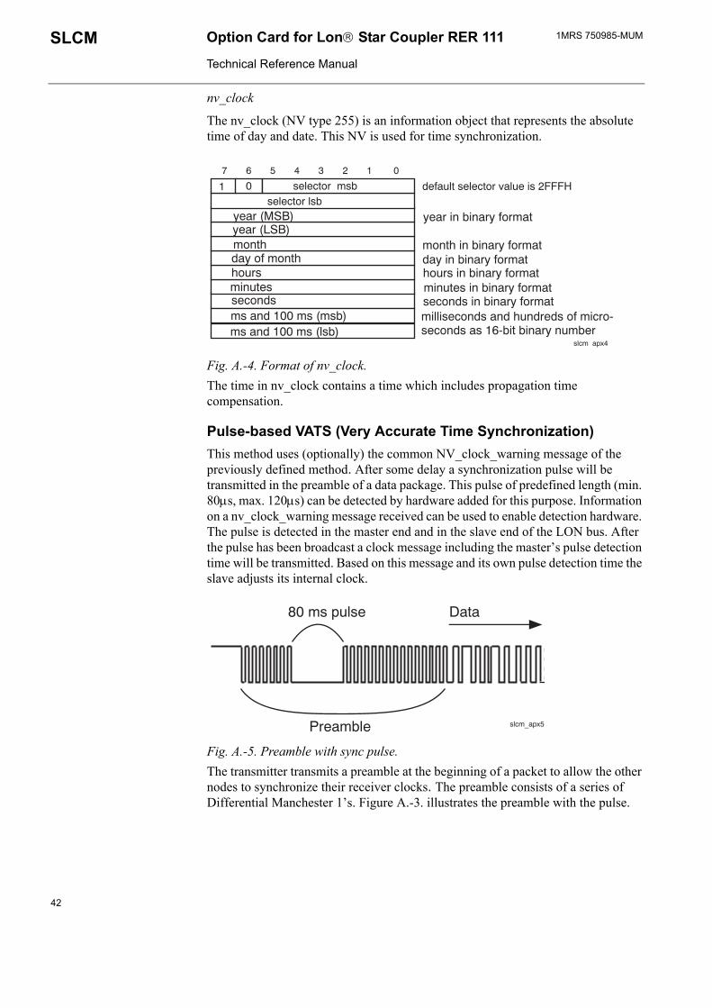
nv_clock
The nv_clock (NV type 255) is an information object that represents the absolute time of day and date. This NV is used for time synchronization.
1 0 selector msbselector lsb
year (MSB)year (LSB)monthday of monthhoursminutesseconds
default selector value is 2FFFH
year in binary format
month in binary formatday in binary formathours in binary formatminutes in binary formatseconds in binary format
ms and 100 ms (msb)ms and 100 ms (lsb)
milliseconds and hundreds of micro-seconds as 16-bit binary number
7 6 5 4 3 2 1 0
slcm_apx4
Fig. A.-4. Format of nv_clock.The time in nv_clock contains a time which includes propagation time compensation.
Pulse-based VATS (Very Accurate Time Synchronization) This method uses (optionally) the common NV_clock_warning message of the previously defined method. After some delay a synchronization pulse will be transmitted in the preamble of a data package. This pulse of predefined length (min. 80µs, max. 120µs) can be detected by hardware added for this purpose. Information on a nv_clock_warning message received can be used to enable detection hardware. The pulse is detected in the master end and in the slave end of the LON bus. After the pulse has been broadcast a clock message including the master�s pulse detection time will be transmitted. Based on this message and its own pulse detection time the slave adjusts its internal clock.
80 ms pulse
Preamble
Data
slcm_apx5
Fig. A.-5. Preamble with sync pulse.The transmitter transmits a preamble at the beginning of a packet to allow the other nodes to synchronize their receiver clocks. The preamble consists of a series of Differential Manchester 1�s. Figure A.-3. illustrates the preamble with the pulse.
42

1MRS 750985-MUM Option Card for Lon Star Coupler RER 111
Technical Reference Manual
SLCM
The nv_sync_pulse network variable has a format of SNVT_state:
1 0 selector msbselector lsb
data, byte 1data, byte 2
default selector value is 2FF4H
16-bit binary value
7 6 5 4 3 2 1 0
slcm apx6
Fig. A.-6. Format of nv_sync_pulse.
1 d selector msbselector lsb
year (msb)year (lsb)monthday of month
hoursminutes
seconds
default selector value is 2FF3H
year in binary format
month in binary formatday in binary formathours in binary formatminutes in binary formatseconds in binary format
SUIV
ms (msb)ms (lsb)res ms (msb)ms (lsb)
millisecondsin binary formatmicrosecondsin binary format
7 6 5 4 3 2 1 0
slcm apx7
Fig. A.-7. Format of NV_sync_time
The nv_sync_time is an information object that represents the absolute time of day and date. This network variable is used as a base network variable for VATS time synchronization. The nv_pulse_time network variable has a format of NV_sync_time (NV type 248):NV_sync_time Value Definition
d direction 0 the message is addressed to an input network
variable (the message is an nv update message or a response to a poll)
year 0...9999 month 0...12 day 1...31 SU Standard/Daylight-saving time
0 standard local time 1 daylight-saving time
hours 0...23 IV Invalid/Valid 0 valid 1 invalid
minutes 0...59 seconds 0...59
43

1MRS 750985-MUMOption Card for Lon Star Coupler RER 111
Technical Reference Manual
SLCM
res
Bit 7 Bit 6 Bit 5 Resolution of the Clock Master
0 0 0 1 µsecond0 0 1 10 µsecond0 1 0 100 µsecond0 1 1 1 millisecond1 0 0 10 millisecond1 0 1 100 millisecond1 1 0 1 second1 1 1 not used
milliseconds 0...999 µseconds 0...999
Bit pattern based VATS This method is quite similar to the pulse-based VATS method, but a different synchronization event is used, i.e. a pulse in the preamble of a message is substituted by a predefined bit pattern in the message. The detection of this bit pattern requires special hardware added to the receiving nodes.
A message with bit pattern is sent explicitly and the message header has a special content: the predefined bit pattern is a destination address given as a fixed Neuron Id. The synchronization event is the end of the last bit in the correct pattern. The destination subnet is configurable and it is defined in entry 0 of the Neuron Address Table. There is no message data in the bit pattern message.
The nv_pattern_time has a format of NV_sync_time. For the detailed format, see the section of Pulse-based VATS.
Leap second insertion
Time Time sent to LON23:59:58 23:59:5823:59:59 23:59:5923:59:60 nothing, SLCM is quiet
00:00:00 00:00:00 (nv_time will be sent here)
00:00:01 00:00:0100:00:02 00:00:02
44

APPENDIX B: Configuring the GPS clock device
When a Meinberg GPS167 is used as a clock reference device the following configurations should be checked:
- serial port parameters (4800 bit/s, no parity, data bits = 8, stop bits = 1)- serial port�s mode of operation (on request)- time zone (this can also be set by SLCM. In that case, use UTC time in the GPS
clock.)- daylight-saving on/off
For more detailed information about configurations above, please refer to Technical Information/Operating Instructions of Meinberg GPS167.
If a clock reference device without time zone and daylight-saving setting support is used, the time zone and the daylight-saving must be set on the SLCM. This is done by updating the input network variables nv_time_zone and nv_daylight_save. For update data value details, see table 6.3.-5 and chapter 7.4.


ADP.FFTeFw
1MR
S 75
0985
-MU
M E
N 0
6.20
05
BB Oyistribution Automation O. Box 699 I-65101 Vaasa INLANDl. +358 10 22 11
ax. +358 10 224 1094ww.abb.com/substationautomation