optimum layout for a turbofan engine p m v subbarao professor mechanical engineering department an...
TRANSCRIPT

Optimum Layout for a Turbofan Engine
P M V Subbarao
Professor
Mechanical Engineering Department
An excellent Choice for Fighter Planes ….

Mixed Flow Turbofan Engine
1 2 3 4 56h
76c
8
0306c pp

Ideal Mixer
• Ideal Mixer : Constant Total Pressure Process.• For a stable operation of the mixer, the inlet static
pressures of core flow and fan flow must be equal.• If they are not, back flow will occur in either the fan
or core.6h6c pp
030706h06c pppp
06h06c MM The stagnation pressure ratio across the fan:
02
06h0p,fan
02
03
p
pr
p
p

1 2 34
5 6h7
6c
8
0p,turbine0p,fancomp0p,02
03
03
04
05
06h0p,fan rrr
p
p
p
p
p
pr
02
04
04
06h
02
06h0p,fan p
p
p
p
p
pr

0p,turbinecomp0p, rr1
0p,turbinecomp0p,1 ττ
Condition for Efficient Mixing

Theory of Jet Propulsion : Just Enough Work
The power inputs to the compressor & fan = The power output of the turbine
turbinefancompressor WWW
comppccpcore
fanppcorecomppfanppcore
Tcfm
TcmTcm
,00,0
,00,0,00
111
111
comppccfanpcomppfanp f
,0,0,0,0,0
111111

comppccfanpcomppfanp f
,0,0,0,0,0
111111
comppcccomppfanp f
,0,0,0,0
1111
compp
comppcc
fanp
f
,0
,0,0
,0
1111

Adiabatic mixing process:
07pfancore06cpfan06hpcore Tcmf1mTcmTcf1m
0706c06h Tfα1αTTf1
fα1
αTTf1T 06c06h
07

00p,turbinecc0,0p,turb0506h TTT
00p,fan0306c TTT
f
T
10 00p,fan0p,turbinecc0,
07
Tf1T
f1
f1TT 0p,fan0p,turbinecc0,
007

1 2 34
5 6h7
6c
8
0prpppppp 0p,fan030706h06c0708
0708 TT
Mixed Flow Turbofan w/o AB

0prppppp 0p,fan030706h06c08
0
1
2
11 prMpp 0p,fan
28808
11
21
0
p
p0p,fan
28M
f
f1TTT 0p,fan0,turbinecc0,
0708
10

1T
T
1
2M 0
0p,fan28 τγ
f1
f1TT 0p,fan0,turbinecc0,
008
α
ατττ
28
088
M2
11
TT
γ
288
28 MRTV γ 88jetmix MRTV γ

Generation of Thrust : The Capacity
acjetmixcoremixedT, V1Vf1mF αα
Propulsive Power or Thrust Power: acmixedT,p VFP
Specific Thrust based on total jet flow S,
f1m
FS
core
mixedT,mixed
α

Thrust Specific Fuel Consumption TSFC
mixedT,
fuel
F
mTSFC
acjetmix
acjetmixcore
fuel
V1Vf1
f
V1Vf1m
mTSFC
αα
αα

Aviation Appreciation
Propulsion Efficiency
Jet the of PowerKinetic Available
Power Thrustηpropulsion
2ac
2jetmix
core
acmixedT,propulsion
V1Vf12
mVF
ηαα

Mixed –Flow Fan : Effect of Bypass Ratio
Non
-dim
ensi
onal
Spe
cific
Thr
ust
Non
-dim
ens i
onal
TS
FCr0p,comp=15
Mac=0.75cc=5.78

Subsonic Operation : Mixed Turbo Fan: Mac=0.75B
ypas
s R
atio
Compressor Pressure Ratio
Fan Pressure Ratio

2
3
4
5
Byp
ass
Rat
io
Compressor Pressure Ratio
Fan Pressure Ratio
Supersonic Operation : Mixed Turbo Fan: Mac=2.0

Subsonic Operation : Mixed Turbo Fan: Mac=0.75
TS
FC
Compressor Pressure Ratio
Fan Pressure Ratio
2
3
4
5

Spe
cific
Thr
ust
Compressor Pressure Ratio
Fan Pressure Ratio
Subsonic Operation : Mixed Turbo Fan : Mac=0.75
2
3
4
5
TS
FC
Compressor Pressure Ratio
Fan Pressure Ratio
2
3
4
5
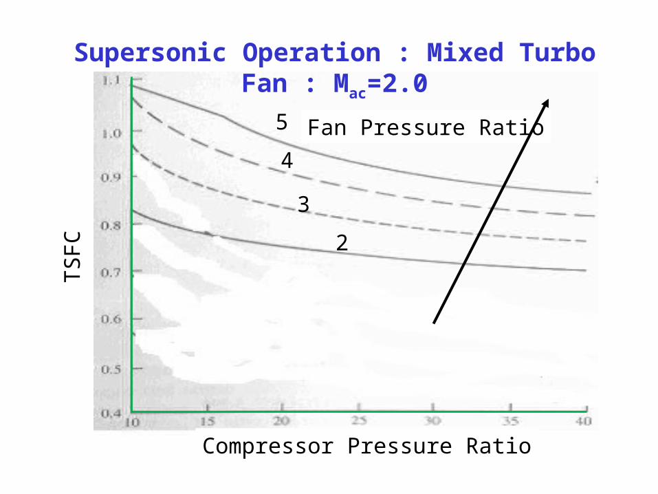
Supersonic Operation : Mixed Turbo Fan : Mac=2.0

Supersonic Operation : Mixed Turbo Fan : Mac=2.0
Spe
cific
Thr
ust
Compressor Pressure Ratio
Fan Pressure Ratio
2
3
4
5

TS
FC
Compressor Pressure Ratio
Fan Pressure Ratio
2
34
5
Byp
ass
Rat
io
Fan Pressure Ratio
Compressor Pressure Ratio
Designs for Fuel Economy: Subsonic Flight

Designs for High Thrust: Supersonic Flight
6h 7
6c
9
Mixed flow turbofan with After Burner:
8

f
T
10 00p,fan0p,turbinecc0,
07
Tf1T
After burner temperatures are generally less than after combustor temperature.
T08 < T05
Generally the percentage of enhancement in thrust is specified to determine temperature of the gas after burner.
cc0,ab0, 0
08
T
T

0
07,00 11..
T
TfffTcVHf combababcombpab
combf
T
10 00p,fan0p,turbinecc0,comb
07
Tf1T

0prpppppp 0p,fan030706h06c0809
0
1
2
11 prMpp 0p,fan
29909
11
21
0
p
p0p,fan
29M
0TT ab0,08

1T
T
1
2M 0
0p,fan29 τγ
009 TT ab,0
29
099
M2
11
TT
γ
299
29 MRTV γ 99jetmix MRTV γ

Generation of Thrust : The Capacity
acjetmixabcombcoremixedT, V1Vff1mF αα
Propulsive Power or Thrust Power: acmixedT,p VFP
Specific Thrust based on total jet flow S,
abcombcore
mixedT,mixed ff1m
FS
α

TF30: Pratt and Whitney Mixed Flow Turbofan Engine
The TF30−P−414 engine is a mixed flow, dual spool afterburning low by pass turbofan designed and manufactured by Pratt and Whitney Aircraft of West Palm Beach, Florida. The engine incorporates a nine stage low pressure compressor including a three stage fan driven by a three stage low pressure turbine; and a 7 stage axial flow high pressure compressor driven by a single stage high pressure turbine.

SPECIFICATIONS:TF30
• Development of TF30−P−414 was initiated in March 1969. • TF30−P−414A was placed in service in October 1982. • 929 TF30−P−414’s were converted to P−414A’s with
conversion kits; conversion completed November 1987. • 269 P−414A’s were purchased.• Max Design Pressure Ratio, SLS :Fan: 2.14 to 1 Overall:
19.8 to 1
• Bypass airflow ratio: 0.878 to 1• Max rated airflow: 242.0 lbs/s

F110-GE-400 Mixed Flow Turbofan Engine

Details of F110-GE 400• The F110−GE−400 engine is a mixed flow, dual spool afterburning
low by pass turbofan designed and manufactured by General Electric Aircraft Engines in Lynn, Massachusetts.
• The engine is of modular construction, consisting of six engine modules, and an accessories gearbox.
• The engine incorporates a 3−stage fan driven by a two stage low pressure turbine; and a 9−stage axial flow high pressure compressor driven by a single stage high pressure turbine.
• To moderate engine performance at various power levels the engine features a variable geometry system.
• The combustor is a through flow annular type. • The hinged flap cam linked exhaust nozzle is hydraulically actuated. • The engine mounted accessory gearbox provides the necessary
extracted power needed to drive the accessories. • The engine control system regulates speeds, temperature levels and
fuel flow for afterburning and non after burning operation. • The lubrication and ignition system are self contained on the engine.• Development was initiated April 1984 and engine was placed in
service in late 1986

SPECIFICATIONS:F110-GE - 400
• Max Design Pressure Ratio, SLS:Fan:3.2 to 1 • Overall: 29.9 to 1
• Airflow Capacity: Max rated airflow: 270.0 lbs/s