optimizing the architectural layouts of curtain walls to...
TRANSCRIPT

Optimizing the Architectural Layouts of Curtain Wallsto Minimize Use of Aluminium
Adam D. Leea,b,∗, Paul Shepherda, Mark C. Everndena, David Metcalfec
aDepartment of Architecture and Civil Engineering, University of Bath, Claverton Down,Bath, BA2 7AY, U.K.
bPTCC Facade Design, Telecom Plaza, 316 Senator Gil Puyat Ave., Makati City, MetroManila, 1200, Philippines.
cCentre for Window and Cladding Technology (CWCT), The Studio, Entry Hill, Bath,BA2 5LY, U.K.
Abstract
During recent decades it has become common to enclose large buildings with
lightweight, weathertight walls that hang, like curtains, from the floor edges.
The frames of these curtain walls are, usually, extruded aluminium – a material
whose production is highly energy-intensive. Although means of enhancing the
thermal performance of building envelopes have been scrutinized, comparatively
little attention has been given to the cost and embodied energy savings that can
be achieved through efficient structural design. No guidelines for efficient use
of aluminium in a curtain wall have been published, and architects therefore
have not known the impact that their decisions have upon the facade’s material
content.
In this study more than 1,000 unique curtain wall systems have been opti-
mized numerically, each one to a different set of design criteria, and the results
show the extent to which aluminium content is influenced by floor height, lo-
cations of supports, number of horizontal members per panel, width of the
extrusions, spacing between mullions, design wind pressure, and the minimum
allowable thickness of aluminium. The conditions in which the amount of metal
∗Corresponding AuthorEmail addresses: [email protected] (Adam D. Lee), [email protected]
(Paul Shepherd), [email protected] (Mark C. Evernden), [email protected](David Metcalfe)
Preprint submitted to Elsevier “Structures” July 25, 2017

required to construct a window wall (glazing spanning between two floors) might
be less than that required for a curtain wall (an uninterrupted, multi-floor
shroud), also have been explored. The results show that substantial metal sav-
ings – reductions of 40 % or more – can be realized by making modest changes to
the layout geometries and specifications that are in common use. The value of
the corresponding construction cost reductions is significant: in the worldwide
construction market, the potential savings are in billions of dollars per year.
The practical steps that an architect and specifier should take in order to
reduce metal content in a curtain wall are set out in a list. These savings are
separate from, and in addition to, any that might be attained by optimizing the
cross-sectional shapes of extrusion profiles.
Unlike improvements in a facade’s thermal performance, which usually re-
quire capital investment in insulating materials for returns that accrue over
decades, material-efficient design methods are free to apply, and the benefits
can be enjoyed immediately.
Keywords: curtain wall, facade design, structural optimization, layout
optimization, topology optimization, embodied energy, green building
2010 MSC: 65K10
1. Introduction
At the start of the last century, when the world’s tallest skyscraper was not
much more than 100 m high [1], it was still common to design tower buildings
with thick masonry walls that served not only to protect occupants from the
weather, but also to support the weight of the floors and to resist lateral forces
[2]. There is however a practical limit [3] to the height of these load-bearing
walls. To create taller towers, another construction technique evolved in two
cities – New York and Chicago – which were already the largest in America,
and which were still growing rapidly [4, p. 492,504]. There, it became the norm
to construct a freestanding structural frame made up of beams and columns, and
then use that frame to carry the floors and walls. By moving away from masonry
2

enclosures, it was possible to build to much greater heights and, partly for this
reason, by the mid-1920s New York had become the worlds’ most populous city
[4, p. 505]. In the process, a market had been established for lightweight exterior
walls that could be suspended, like curtains, from the edges of a tower’s floors
[5].
In the earliest of these curtain walls, the main structural component – the
vertical member, or mullion, spanning from floor to floor – was a simple steel
section. At those locations where windows were needed, the glass was carried
by a separate metal frame fixed mechanically to the mullion [6, p. 108]. For
decades this was the dominant design approach and, in the late 1950s, it was
the method used to create the facades of the first fully-glazed towers. It was
however in these early “glass box” buildings that the limitations of a curtain
wall made up of window frames supported by steel verticals, particularly diffi-
culties in achieving an effective weather barrier, were revealed [7, p. 17]. Higher
performance standards were attained as facade engineers exploited the free-
dom afforded by the aluminium extrusion process to create mullions with more
complex cross-sectional shapes. Conventional structural forms – I-sections, T-
sections and boxes – were combined with features such as gasket keyways, so
that a separate frame for glass was no longer required [e.g. 6, p. 111; 8].
During the ensuing period of innovation there emerged a new type or variety
of curtain wall, the unitized systems, the first of which was patented in America
in 1962 [9]. Facades of this type are made up of discrete panels, each one
being, typically, one floor in height, prefabricated and preglazed away from the
building site. The anatomy of such a panel is shown in Figure 1. Because of
the advantages conferred by factory fabrication [10 p. 4-5; 11 p. 86], today the
majority of the world’s new curtain wall is unitized [12, p. 82].
When two unitized panels are brought together, side by side at the exterior
of a building [13, in photos, p. 69], their extruded aluminium frames engage
to create a two-piece mullion – the split-mullion – within which the joints are
weatherproofed by rubber gaskets. Each of the two profiles in a modern split
mullion is, usually, shaped like the letter E, and many extrusions of this sort
3

Figure 1: Parts of a unitized curtain wall panel for a flat facade, viewed from the side facing
the interior of the building. For clarity, cosmetic trims, insulation, and barriers preventing
the spread of fire and smoke, are omitted from this diagram.
4

may be found in the industry’s technical literature [e.g. 14, p. 6-51; 15, p. 90;
16, p. 52; 17 pp. 6-11; 18]. In the particular example shown in Figure 2, the base
shape of both the male and female profile is E-shaped, but an additional web
has been added to create a box in the exterior part of the female side.
Figure 2: The male and female extrusions (Left), together, form a unitized curtain wall’s split
mullion. In the idealized model of the mullion extrusions (Right), the P series of dimensions
can be modified parametrically. Other input parameters control whether the elements labelled
P04 , P09 , and P18 , as well as the group of elements labelled P13 , P14 , and P15 , are included
in the model.
In this paper, curtain wall has been introduced in its historical context in
order to emphasize that, by the standards of the construction industry, the tech-
nology is still young. It was only in the 1980s that unitized building techniques
entered the mainstream [14, p. 2-4]. The first structurally-glazed tower facade –
using sealant to secure the glass to the aluminium frame, as shown in Figure 2
and discussed in Section 3.9 – was completed as recently as 1986 [13, p. 53].
Design know-how has had to propagate rapidly between contractors, especially
5

during the period between 2005 and 2012, when the global market for unitized
curtain wall doubled in value, to around US $ 12 billion per year [12, p. 82]. It
would therefore be unsurprising to find that opportunities for further technical
refinement exist within this relatively new field.
The authors of this paper have previously examined the efficiency with which
aluminium is used in bespoke curtain walls conceived, by respected specialists,
for real facades [19]. The mass of aluminium in twenty-four existing unitized
wall systems, each one custom-designed for a specific building, was compared
with the mass of metal in a numerically optimized design complying with the
same performance criteria. The solutions obtained numerically were found to
be consistently superior to those conceived by experienced facade designers. It
proved to be easy to identify cases in which metal savings of 20 % or more
could have been achieved through better optimization of the extrusion shapes.
This finding is of interest for at least two reasons. One, most obviously, is that
material savings bring cost savings. The other is that, of all the materials used
in significant quantity in construction, aluminium has the highest embodied
energy per unit mass (approximately 80 times that of reinforced concrete [20]),
so there is an environmental incentive to use this metal sparingly.
This past investigation demonstrated that the task usually undertaken by
a curtain wall contractor’s designers – finding the most efficient cross-sectional
shapes for extruded framing members capable of satisfying a given set of perfor-
mance requirements – can be handled effectively, or more effectively, by compu-
tational algorithms. The research described in this present paper goes further:
it investigates the effects that decisions made by architects and their consultants
– regarding the facades’ layout, and its performance criteria – have upon the
mass of metal in a building’s curtain wall.
The method of investigation has been to consider, initially, the geometric
layout and specifications for an archetypal curtain wall – a wall typical of the
sort used to enclose large numbers of modern buildings – and then, by varying
one design constraint at a time, it has been possible to quantify the extent to
which each of the variables influences the mass of metal in the wall system.
6

In this paper, the specifications for a total of more than 1,000 unique curtain
walls have been defined. In each case the wall system’s extrusion shapes have
been optimized using numerical algorithms implemented in the software whose
workings are outlined, briefly, in Sections 1.1, 1.2 and 1.3. Results are set out in
Section 2: these show the extent to which the mass of aluminium is affected by
changes in floor-to-floor height, mullion bracket location, number of transoms,
mullion width, mullion spacing, and also by the magnitude of the design wind
pressure. The implications of these results, which are presented in Section 3,
are formulated as a set of practical guidelines for those architects and facade
engineers whose aim it is to make efficient use of material in their buildings’
facades.
1.1. Acweds Software for Curtain Wall Optimization
For each unique combination of facade layout and performance specification,
the shapes of the extrusions in an optimized curtain wall system have been found
numerically. The optimization software, named Acweds, was written for this
purpose. The program’s features and complexities – it is made up of 5,000 lines
of C++ code – are not detailed here, but a description of its workings, as well as
the steps taken to test its efficacy, has been published separately [19]. Its four
main operative parts are:
(a) A parameterized geometric model of a unitized curtain wall system’s extru-
sions.
(b) A set of procedures by which to evaluate whether proposed extrusions are
structurally viable, and whether they can in practice be manufactured. One
of the verifications made during these analyses ensures that the magnitude
of the mullion’s deflection is not greater than the specified allowable. Also,
stresses are computed in each inter-transom span, for each of the panel’s
mullion profiles, for each specified wind load condition: these values are
checked, using the algebraic rules given in the Aluminum Design Manual
(ADM) [21], to ensure that they do not exceed the allowable proportion
7

of the extrusion’s yield strength or local buckling limit or lateral torsional
buckling limit.
(c) A numerical search function, a genetic algorithm (GA), programmed to
look for that set of dimensions that, when applied to the parametric model,
produces a curtain wall design satisfying the constraints using the minimum
possible quantity of aluminium.
(d) Computer code capable of converting the program’s data into human-readable
format. Output includes structural calculation reports, drawings of opti-
mized extrusions, and statistics with which to track the search algorithm’s
progress.
1.2. Structural Design of Glass
In order to admit light to a building, and in order to allow the occupants to
see outside, it is usual that the sheet material used to cover a large proportion
of a curtain wall’s surface area – sometimes the entire surface area – will be
glass. Although the central goal of this research is to find effective means by
which to minimize the mass of aluminium in a curtain wall, it is desirable to
understand also the way in which those strategies influence the thickness of the
glass. This information is of interest because the amount of energy required to
create architectural glass, by melting silica sand and subsequently heat treating
the cut panes, is energy intensive. The finished material’s embodied energy, and
hence its cost, is significant, although in a typical curtain wall glass contributes
less than aluminium to the total embodied energy and total cost. So that these
contributions may be assessed, Acweds has been programmed to calculate the
minimum required thickness of each glass pane in the curtain wall panels that
it analyzes.
The load resistance of a glass pane is determined using a closed-form alge-
braic expression deduced from the British Standard for glazing in buildings [22].
Glass deflections, on the other hand, are computed by the algebraic method set
out in of ASTM E1300 [23, Appendix X1]. The reason for mixing the design
rules published in two different countries is simply that the British standard
8

does not provide a method for finding deflections, and the ASTM’s procedure
for estimating load resistance relies on graphs whose data are not readily incor-
porated within a computer program. So, where glass thicknesses are presented
in this paper, they should be considered to be approximate.
1.3. Material Cost and Embodied Energy
For the purpose of estimating the combined cost of glass and aluminium
in a given curtain wall design, the price of extruded and painted aluminium
has been taken to be US $ 3 per kg. The cost of tinted, heat strengthened,
monolithic glass with a single coating of metal oxide, has been assumed to vary
linearly with the thickness of the pane. Based on a review of current “factory
gate” prices – that is to say, without transportation fees, taxes or duties – for
high-volume glass purchases [24, 25], the authors have developed the following
algebraic expression to describe glass costs: -
cgl = 4 + 3100 · tgl (1)
where, cgl is the cost of glass in US $ per m2, and,
tgl is the thickness of the pane, in m.
The embodied energy in extruded aluminium and tempered glass is taken
to be 154 MJ/kg [20, p. 74] and 36 MJ/kg [mean value, 20, p. 16] respectively.
2. Numerical Optimization Studies
Throughout the history of the “glass box” architectural style, critics have
complained that the curtain wall facades of many of the world’s large buildings
are similar to one another in appearance. There is some truth in this allegation.
Because of practical constraints, different architects arrive at similar design so-
lutions: floor-to-floor heights vary only within a narrow range; a rectilinear grid
is the most practical arrangement for the facade’s skeletal frame; transportation
logistics limit the sizes of curtain wall panels; the building’s occupants will ex-
pect to see out of windows positioned at eye level; and so on. In the context of
9

this study, it is an interesting observation that so many curtain walls are alike:
metal optimization heuristics revealed by studying one building’s curtain wall
are likely to be effective when applied to the large numbers of walls having simi-
lar geometric layouts and performance requirements. The layout configurations
of a selection of common curtain walls in the real world, and their performance
specifications, have been examined, and popular values for dimensions and de-
sign constraints have been determined. A reference layout, following the popular
dimensions, is shown in Figure 4, and the reference set of performance targets
is given in Table 1. The shapes of a set of weight-minimized curtain wall extru-
sion profiles for a curtain wall system having this grid geometry, and designed
to these performance criteria, was determined using Acweds. The optimized
mullion profiles are shown in Figure 3.
Having established this benchmark, one design constraint at a time was
selected – initially, the distance between the top of the curtain wall panel and its
attachment bracket – and the value of the constraint was varied in discreet steps
through a wide range. The effect that these changes have upon the optimized
wall system’s aluminium content were observed. The same process was repeated
to investigate the effect of changing other design constraints, and the results are
described in the following sub-sections.
In plots of data points, some of the noise or scatter is attributable to the
stochastic nature of the genetic algorithm: the best solutions identified during
successive curtain wall optimization runs are not necessarily uniformly close to
the global optimum. The extent of the spread could be reduced by, say, running
Acweds more than once for each set of design criteria, and then presenting the
best of the solutions found. Alternatively it would be possible to allow evolution
to occur in a larger population, or for more generations. Such strategies would
however be more costly in terms of computational resources. The authors have
taken the view that, as all of the algorithmically-found designs are known to
comply with the structural code, slightly sub-optimal results are still adequate
for practical engineering purposes.
10

Figure 3: Shapes of the mullion profiles optimized to meet the performance criteria set out
in Table 1, and the facade layout geometry shown in Figure 4. Dimensions are in millimeters.
11

Figure 4: Dimensioned elevation and section views showing the layout of the normative
reference curtain wall considered in the numerical optimization studies. The vertical distance
between the fulcrum of the bracket and the fulcrum of the stack joint, dC , is the “stack-height”.
12

Table 1: Layout dimensions, alloy type and performance criteria for normative standard
curtain wall system considered in numerical analysis.
Constraint Value Comment
Extruded metal thickness: 3 mm ≤ Pi ≤ 12 mm. [19, Fig. 5]
Front-to-back mullion depth: 60 mm ≤ Pd ≤ 240 mm. See Figure 2.
Mullion width: 60 mm ≤ Pw ≤ 120 mm. See Figure 2.
Interior flange separation: K02 = 10 mm. See Figure 2.
Gasket clearance: K04 = 1.5 mm. See Figure 2.
Exterior flange separation: K05 = 14 mm. See Figure 2.
Outer face to rainscreen: K06 = 46 mm. See Figure 2.
Sum of transom web thicknesses: 15 mm. ∗See note below.
Total area of reference transoms: 4965 mm2. ∗See note below.
Reference transom depth: 150 mm. ∗See note below.
Panel width: dM = 1,500 mm. See Figure 4.
Bracket to bottom of panel: dA = 3,300 mm. See Figure 4.
Vertical distance between brackets: dB = 0 mm. (Only one
bracket per floor.)
See Figure 4.
Stack height: dC = 400 mm. See Figure 4.
Top of vision span to top of panel: dG = 1,040 mm. See Figure 4.
Height of unbraced vision span: dH = 2,630 mm. See Figure 4.
Top of spandrel to top of panel: dK = 100 mm. See Figure 4.
Height of spandrel: dL = 860 mm. See Figure 4.
Maximum deflection: min{20 mm, Span/175}.
Wind pressure: +2.8 kPa and -3.5 kPa.
Aluminium alloy: 6063-T5.
∗A selection of different existing unitized curtain wall systems have been examined,
and the mass of metal in a typical set of horizontal structural members has been
determined for the case in which the front-to-back depth of the sections – Pd in Figure 2
– is 150 mm. In order to estimate the mass of metal in the horizontal profiles in other
conditions, it has been assumed that the lengths of their webs change so that the depth
of the section matches the depth of the mullion.
13

2.1. Floor Height
If the design of the reference curtain wall is modified to suit a new floor-to-
floor height, then the amount of metal in the facade will change as shown in
Figure 5. The plot shows the variation in mass of metal per unit area of facade.
When quantifying the consequence of an increase in floor height, it should be
remembered that not only will the mass per area rise, but also, assuming that the
number of building floors remains constant, the total facade area will increase.
7
7.5
8
8.5
9
9.5
10
10.5
2500 3000 3500 4000 4500
Mass
of
alu
min
ium
(kg·m
−2)
Floor-to-floor height (mm)
Figure 5: Influence of floor-to-floor height upon the mass of metal per unit area of optimized
curtain wall.
From these results it can be seen that changes in floor-to-floor span af-
fect strongly the facade’s aluminium content. If the number of floors in the
building remains constant and the height of each floor is increased by 10 % –
from 3700 mm to 4070 mm – then the total mass of metal in the structurally-
optimzied facade will rise by 19.3 %. An architectural team wishing to use ma-
terial efficiently should therefore ensure that floor-to-floor spans are no larger
than necessary.
14

2.2. Stack Height
Figure 6 plots the weight of metal in the members of a family of curtain
walls. The geometric arrangement of these walls is matched to that shown in
Figure 4 except that, in each member of the group, the distance between the
top of the panel and the attachment bracket, the “stack height”, is different.
Figure 6 shows that, if the bracket connection point is not at the very top of
the panel, which is the location often chosen by architects, but is moved down
by approximately 17 % of panel height, then the weight of metal in the curtain
wall can be reduced by more than 25 %. The importance of this observation is
worth emphasizing: simply by moving the mullion’s support bracket away from
the very top of the panel, the magnitude of bending moment in the main span
is lessened [bending moment shown in 19, Figure 4], and the mass of aluminium
in the facade may be reduced by one quarter.
2.3. Unbraced Length & Mullion Width
The cross-sectional shapes of mullions optimized for the different curtain
wall panels in Figure 7, having between one and four transoms, are presented
in Figure 8. The graph in Figure 7 shows that, if the number of transoms is
two or more, then in the common range of unitized mullion widths – between,
say, 75 mm and 105 mm – changes in the width of the mullion have little ef-
fect upon the system’s aluminium content. If the number of transoms in the
panel is increased above two, each extra transom increases the metal mass by
approximately 0.8 kg/m2.
If the panel has only one transom, and if the mullion is narrow, then the
governing structural design consideration is the stability of the slender vertical
members. In this situation the amount of metal needed to make the slender
mullions resistant to buckling is greater than the amount of metal needed to
reduce the mullion’s unbraced span by introducing an additional transom.
2.4. Minimum Extruded Thickness
Figure 9 shows the effect that the value of the specified minimum metal
thickness has upon the mass of aluminium in this study’s reference curtain wall
15

7.5
8
8.5
9
9.5
10
10.5
0 200 400 600 800 1000 1200 1400 1600 1800
0 0.1 0.2 0.3 0.4 0.5
10
610810
1010
12101410210
4001600
1800
Mass
of
alu
min
ium
(kg/m
2)
Stack height, dC in Fig. 4 (mm)
Stack height as a proportion of floor-to-floor height (dimensionless)
10 mm 210 mm 400 mm 610 mm 810 mm 1010 mm 1210 mm 1410 mm 1600 mm 1800 mm
Figure 6: The graph shows the mass of aluminium in the members of a family of optimized
curtain wall designs, each with a different stack height (dc in Figure 4).
16

1 Transom 2 Transoms 3 Transoms 4 Transoms
8
8.5
9
9.5
10
10.5
11
11.5
12
60 80 100 120 140 160
Mass
of
alu
min
ium
(kg·m
−2)
Width of split mullion (mm)
Stack joint plus 1 transom. —— Slender range.Stack joint plus 2 transoms.Stack joint plus 3 transoms.Stack joint plus 4 transoms.
Figure 7: Plot (bottom) shows variation in mass of aluminium with mullion width, for four
different curtain wall panel configurations (above). Other than the number of their transoms,
panels are the same as those shown in Figure 4. The solid line on the graph is a moving
mean mass of metal for panels with one transom, in which the mullion is slender and lateral
torsional buckling is the governing structural design consideration. At high slenderness ratios,
the mullion cross-sections are inefficient: if mullion width is narrower than 80 mm then a panel
with two transoms requires less aluminium than in a panel with one transom.
17

system. The shapes of four different pairs of optimized mullion profiles, created
by Acweds to meet minimum metal thickness requirements of 1, 2, 3 and 4 mm,
are shown. All of the profiles meet the structural design criteria – for resistance
to local buckling, lateral torsional buckling and so on – and they are drawn to
the same scale. It can be seen that the optimal depth of the profiles decreases
as the specified minimum extrusion thickness increases, and at the same time
the mass of metal in the wall system rises. Based on this analysis it appears
that a change in minimum thickness from 3.2 mm (or 1/8 inch), a figure that
is frequently found in the technical specifications for facades of buildings in
North America, to 2.2 mm, causes the overall mass of aluminium in the curtain
wall system to fall by approximately 18 %. Therefore, the specifier’s choice of
minimum thickness will have a significant effect upon the amount of metal in the
optimized design. Although it is currently impractical to extrude or to handle
curtain wall extrusions with webs or flanges as thin as 1 mm, the data from
this study show that if new technologies were to be developed – for example,
lightweight composite framing members created by bonding thin aluminium
sheets to a low-modulus filler material – then more efficient designs could be
realised.
Figure 8: Mullions optimized for four different curtain wall panels – those shown in the upper
diagram of Figure 7 – each with a different number of transoms.
18

5
6
7
8
9
10
11
12
13
14
1 2 3 4 5 6
Mass
of
alu
min
ium
(kg/m
2)
Minimum metal thickness (mm)
Optimized Curtain Wall Designs from AcwedsStraight Line of Best Fit
1 mm Minimum 2 mm Minimum 3 mm Minimum 4 mm Minimum
Figure 9: (Top) Weight of aluminium in the curtain wall shown in Figure 4, plotted against
minimum allowable metal thickness. (Bottom) Shapes of mullions optimized for metal thick-
ness minima of 1 mm, 2 mm, 3 mm and 4 mm. Male mullions are drawn with fill, while female
mullions are drawn in outline.
19

2.5. Mullion Spacing
Figure 10 shows the influence that the curtain wall’s module width – the
horizontal distance between mullions – has upon metal content.
6
8
10
12
14
16
18
20
500 1000 1500 2000 2500 3000 35007
7.5
8
8.5
9
9.5
10
10.5
11
11.5
12
Gla
ssth
icknes
s(m
m)
Mass
of
alu
min
ium
(kg/m
−2)
Mullion spacing (mm)
45
50
55
60
65
70
75
500 1000 1500 2000 2500 3000 35001900
2000
2100
2200
2300
2400
2500
2600
Cost
($/m
2)
Em
bodie
dE
ner
gy
(MJ/m
2)
Mullion spacing (mm)
Mass of aluminium (kg/m2)Thickness of vision glass (mm)Thickness of spandrel glass (mm)
Cost of Aluminium and Glass (US$/m2)Embodied Energy in Aluminium and Glass (MJ/m2)
Figure 10: The upper graph shows how the mass of aluminium in an optimized curtain
wall, and the thickness of its vision and spandrel glass, change with the horizontal spacing be-
tween mullions. The lower graph shows the approximate combined cost, and the approximate
combined embodied energy, of the aluminium and glass.
The plot shows panels of up to 3.5 m in width but, in practice, because of
transportation and handling constraints, panels of so wide are unusual.
20

As panel width increases, so the mass of aluminium in the wall falls. At
the same time however, if the panel is glazed, then the thickness of glass must
increase. The combined cost of aluminium and glass, as well as the combined
embodied energy, are shown in Figure 10. Both cost and embodied energy are
at a minimum when one of the common architectural glass thicknesses – 6 mm
or 8 mm – is chosen, and when the separation between mullions is as wide as is
possible without causing excessive stress or deflection in the glass.
2.6. Wind Pressure
The forces resulting from the action of wind upon a building’s facades may
be predicted by testing a scale model in an atmospheric wind tunnel. This
method has been widely used for many decades, and its fundamental technical
aspects are well documented [26, 27, 28]. Most of the world’s building codes
allow a facade’s design wind loads to be determined either by wind tunnel test-
ing or, alternatively, using formulas that take account of the building’s location,
its shape and the topography of its surroundings. Architects and their consul-
tants usually are advised that the costs associated with a wind tunnel study
are outweighed by the resulting material savings [29, pp. 88-89; 26, p. 4]. This
assertion, that wind tunnel testing results in cost savings, appears often in the
marketing materials of wind engineering firms. To quote phrases used on the
internet by three of these firms: there are “massive cost-saving implications”;
wind tunnel testing “generally results in significant savings in the cost of the
facade”; and there may be “a cost to benefit ratio of 1:30 in carrying out a
cladding pressure study”.
While various authors, [e.g. 28], have compared the magnitudes of the design
pressures obtained by wind tunnel modelling with those calculated using the
construction codes, until now little information has been available to describe
the relationship between a facade’s design pressure and its material content. It
has therefore been difficult for architects and building owners, the parties who
commission wind tunnel studies, to evaluate the sort of cost-saving claims made
in the quotations above.
21

Figure 11 shows, for a range of different design wind pressures, the minimum
mass of metal required to construct this study’s reference curtain wall system.
It is usually the case that the magnitude of the positive, or inward-acting,
pressure is less than that of the negative, or outward-acting, load. So, for
each of the cases considered in this design pressure study, the magnitude of the
positive wind load has been maintained at 80 % of the magnitude of negative
wind load. These results may be used to estimate the metal savings associated
with a given reduction in design wind pressure, assuming that the structural
design of each wall panel is optimized to match its nominal design pressure. In
practice however, as discussed in Section 3.6, if a wind tunnel study results in a
pressure zoning scheme that is more complex than that which would have been
obtained from a construction code, then it may be impractical to create different
curtain wall panels for each of the design pressure conditions. Consequently, the
magnitude of the metal saving indicated in Figure 11 should be considered to
be an upper bound.
2.7. Comparison Between Curtain Wall & Window Wall
Amongst other popular types of exterior envelope system, an architect might
choose a curtain wall – a continuous multi-storey envelope mounted outside the
building structure – or a window wall, which spans only from the upper side of
one floor slab to the underside of the floor above [30, p. 32]. The sections in
Figure 12 show these two different types of construction.
While it might at first seem that, since a curtain wall must cover a greater
area it will contain more material than a window wall, this argument neglects
a difference in the bending moment distribution in the mullions of the two
systems. The vertical members of the curtain wall behave as continuous beams
spanning multiple storeys [19, Fig. 4], while vertical members of the window wall
are simply supported at the head and sill. The result is that the magnitude of
the moments in mullions, and hence also the required mass of aluminium, may
be greater in a window wall than in a curtain wall.
Acweds was used to create a family of unitized window wall designs, each
22

6
8
10
12
14
16
18
20
1000 2000 3000 4000 5000 6000 7000 8000 9000 100005
6
7
8
9
10
11
12
13
Gla
ssth
icknes
s(m
m)
Mass
of
alu
min
ium
(kg/m
2)
Wind pressure (N/m2)
35
40
45
50
55
60
65
70
75
80
85
1000 2000 3000 4000 5000 6000 7000 8000 9000 100001200
1400
1600
1800
2000
2200
2400
2600
2800
3000
3200
Cost
($/m
2)
Em
bodie
dE
ner
gy
(MJ/m
2)
Wind pressure (N/m2)
Mass of aluminium, (kg/m2)Thickness of vision glass (mm)Thickness of spandrel glass (mm)
Cost of Aluminium and Glass (US$/m2)Embodied Energy in Aluminium and Glass (MJ/m2)
Figure 11: Upper graph shows the effect that variation in design wind load has upon weight
of aluminium and thickness of glass in an optimized curtain wall system. Lower graph shows
the effect upon and material cost and embodied energy.
23

of a different vertical span, and each optimized for minimum metal weight. The
frames of the window wall panels were simple rectangles without any transom
between the head and sill members, and the vertical height of the panels varied
between 2.1 and 3.7 m. The front-to-back depth of each panel’s horizontal mem-
bers was set to match the depth of its mullion: for a mullion depth 150 mm the
sum total cross-sectional area of the sub-head, head, head clip, sill and sub-sill,
as shown in Figure 13, is 4865 mm2. Other aspects of the specification of the
window wall were set to match the curtain wall specification summarized in
Table 1. Figure 13 shows the cross-sectional form of a window wall’s head and
sill. The system shown in these diagrams has extruded caps at the perimeter of
the glass, but, as for the previous studies of curtain walls, such caps are ignored
in the computation of metal weight.
Figure 14 shows the way in which metal mass varies with the height of
the window wall. Also marked on this graph are the masses of metal in two
curtain wall systems designed to the same performance specifications: one is
the reference curtain wall shown in Figure 4, and the other is similar but with
a distance of 640 mm between stack joint and bracket. These two curtain wall
layouts have been chosen for comparison because they are the common and
Figure 12: Elevation and section views of a curtain wall (left), and a window wall (right). In
the elevation views, panel sizes are indicated with a heavy, broken line.
24

Figure 13: Cross-sectional form of horizontal members in a window wall: the sub-head and
head (left), and the sill and sub-sill (right). An outline of the vertical mullion is shown above
the sill.
25

geometrically optimized geometries that an architect might reasonably consider
as alternatives to the window wall facade.
The results indicate that, for this set of design criteria, if the height of
an optimized window wall is greater than approximately 80% of the vertical
distance between floors, then it will contain more aluminium than an optimized
curtain wall, even though the curtain wall covers a greater area.
In order to make a fair comparison between the two different types of wall
system, the material used to create those parts of a facade that exist between
the horizontal bands of window wall also should be taken into consideration. If
construction costs are to be compared, then it should be noted that the window
wall requires site-applied waterproofing and coordination between trades. For
all of these reasons a window wall is unlikely to be more economical than a
curtain wall unless its span is considerably less than 80 % of the floor-to-floor
height.
3. Research-Based Heuristics for Efficient Curtain Wall Design
Metal-saving strategies that might be used by the different members of a
building’s facade design team – the architect, the specialist consultant and the
facade contractor – are presented below. These recommendations follow from
the numerical studies described in this paper.
3.1. Floor Height
As a building’s floor-to-floor height rises, the mullions in its facade must be
made stronger and stiffer in order to span a greater distance, and so the mass
of metal per unit area of facade will increase. If the number of floors remains
constant then, because the building becomes taller, the total area of facade also
will increase.
The data presented in Figure 5 shows that a 10 % increase in floor-to-floor
height – from 3700 mm to 4070 mm – adds 19.3 % to the total mass of metal
in the facade. For this reason the vertical distance between a building’s floors
should be no larger than necessary.
26

4
5
6
7
8
9
10
11
12
2000 2200 2400 2600 2800 3000 3200 3400 3600 3800
A 2970 mm high window wallcontains the same mass ofaluminium as a curtain walloptimized for 3700 mm floor-to-floorspan.
Mass
of
alu
min
ium
(kg/m
2)
Vertical span of window wall (mm)
Window wall (metal mass per m2, averaged over entire facade area)Curtain wall, 400 mm stack height (Table 1)Curtain wall, 640 mm stack height (Fig. 6)
Figure 14: Relationship between mass of aluminium and height of window wall. The mass of
metal in this study’s reference curtain wall system (Figure 4) is shown for comparison. Also
shown is the mass of metal in a modified version of the reference wall, in which the mullion’s
support bracket is positioned at the optimal distance from the top of the panel.
3.2. Location of Mullion Brackets
It has been shown in Section 2.2 that, when deciding upon the layout for a
unitized curtain wall, considerable metal savings can be achieved if each mul-
lion’s support bracket is moved downward, away from the end of the mullion –
that is to say, away from the top of the panel. In the results presented in Fig-
ure 6, the optimum distance between bracket and stack joint is approximately
17 % of floor-to-floor span.
If, as is commonly the case, mullion brackets are attached to the building’s
structure at the upper side of the floor slab, as shown in the left hand side of
Figure 15, then the structurally optimal position for the stack joint will be close
to knee height. On the other hand, if an architect wishes to align the bottom
of the curtain wall’s panels with the top of the floor, as show at the right
hand side of Figure 15, then, in order to achieve the optimal stack-to-bracket
27
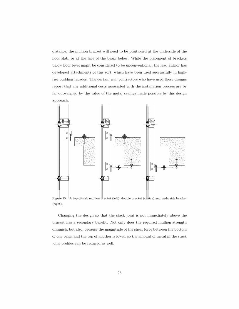
distance, the mullion bracket will need to be positioned at the underside of the
floor slab, or at the face of the beam below. While the placement of brackets
below floor level might be considered to be unconventional, the lead author has
developed attachments of this sort, which have been used successfully in high-
rise building facades. The curtain wall contractors who have used these designs
report that any additional costs associated with the installation process are by
far outweighed by the value of the metal savings made possible by this design
approach.
(A) (B) (C) (D)Figure 15: A top-of-slab mullion bracket (left), double bracket (centre) and underside bracket
(right).
Changing the design so that the stack joint is not immediately above the
bracket has a secondary benefit. Not only does the required mullion strength
diminish, but also, because the magnitude of the shear force between the bottom
of one panel and the top of another is lower, so the amount of metal in the stack
joint profiles can be reduced as well.
28

3.3. Number of Transoms
In order to minimize the extent to which a curtain wall’s structural lattice
interferes with the building’s occupants’ view of the world outside, an architect
might have a preference for designs in which the size and number of framing
elements is kept to a minimum. Panels might be designed with a single pane
of glass spanning from floor to ceiling, and mullions might be made as narrow
as possible. However, such an approach is likely to result in inefficient use of
aluminium. If the structural analysis of mullions is carried out in accordance
with the curtain wall industry’s current guidelines for best practice [for example
31], ignoring any lateral support provided by glass or other infill materials then,
as shown in Figure 7, an optimized curtain wall panel with floor-to-ceiling glass
and mullions narrower than about 80 mm will contain more metal than an op-
timized design in which the vision glass is divided by one additional horizontal
member.
Efficient designs can be achieved in panels with floor-to-ceiling glass, provid-
ing the mullion is not too slender. For the curtain wall layout studied here, in
which the floor height is 3700,mm, the use of split mullions of around 100 mm
in width was found to minimize the mass of metal in the facade.
3.4. Minimum Metal Thickness
The model specifications and design commentaries prepared by the curtain
wall industry’s technical bodies [32, 14, 30] place no restrictions upon the thick-
ness of aluminium in extruded structural profiles, except of course that the
metal thickness should be sufficient to ensure satisfactory structural perfor-
mance. However, many technical specifications for the construction projects of
governments and private developers stipulate that extrusions in which the thick-
ness of metal is less than a certain minimum are either forbidden or that they
require special approval [e.g. 33, p. 16-9]. A specifier might, for instance, insist
that in all structural extrusions the thickness of metal is not less than 3 mm or
3.2 mm. Section 2.4 of this this present study shows that the overall size of an
optimized framing member increases as the minimum allowable metal thickness
29

is decreased. However, even if the profiles become larger, the total mass of metal
in the wall system can be reduced. The results presented in Figure 9 indicate
that simply by changing the allowable minimum metal thickness from 3.2 mm
to 2.2 mm, the curtain wall’s metal content falls by 18 %.
The recommendation arising from these findings is that architectural teams
should question whether it is really necessary to stipulate a minimum metal
thickness. Instead, metal can be saved if curtain wall contractors are allowed to
develop their extrusion profiles without geometric restrictions, other than that
the shapes must be shown to comply with the prevailing structural design rules.
Specifiers may, hypothetically, have been imposing minimum metal thick-
nesses as an indirect means of controlling another aspect of a curtain wall’s
performance. It might be that a requirement for thicker metal has been intro-
duced to tighten dimensional control during the extrusion process, or to increase
a curtain wall’s capacity to attenuate noise. Perhaps specifiers believe that an
extrusion will be weak if its plate elements are thin, even if the profile complies
with prescriptions of the structural design codes. The authors of this paper
argue however that it is preferable to specify the desired criteria directly. In the
case of these examples, rather than use metal thickness as a proxy, it would be
better to set geometric tolerance limits, or to indicate the required standard of
acoustic performance.
3.5. Horizontal Distance Between Mullions
It has been shown, in Section 2.5, that as a curtain wall system’s mullions
are moved apart, so the mass of metal in the optimized facade will decrease,
but at the same time the mass of glass will increase. Some guideline is needed
to achieve an efficient compromise. Whether it is the objective to minimize
embodied energy or to minimize cost of metal and glass, and whether the curtain
wall is to be glazed with monolithic or insulated glass, Figure 10 suggests a
reasonable optimization strategy. First, one of the common architectural glass
ply thicknesses, 6 mm or 8 mm, should be chosen; next, the horizontal spacing
between mullions should be set to the maximum at which the chosen glass is
30

structurally adequate. Also a check should be made to ensure that the facade’s
typical panes can be cut from “jumbo” sheets, which are approximately 3 m by
6 m [34, p. 226], without excessive wastage.
If a wall’s design wind loads are determined using a code, rather than by
wind tunnel testing, then a large facade will, typically, be divided into a small
number of simple rectangular zones, and each zone will have a different wind
pressure. Because the optimal mullion spacing depends upon the design load,
in order to make the most efficient use of material, an architect might, for
example, choose a wider mullion spacing in the central part of a facade, where
the magnitude of the design load is lower, and a closer spacing in the proximity
of corners, where the magnitude of wind pressure is greater.
Maximizing the horizontal separation between mullions not only lowers the
mass of metal in the curtain wall, but also benefits thermal performance because
less heat passes through insulated glass than through the frame [35, p. 32].
3.6. Wind Tunnel Testing
If a building’s design loads are calculated using the rules given in a code, then
each of its facades will be divided into a small number of simple, rectangular
zones, and a different design wind pressure will be assigned to each zone [26,
p. 11]. If, on the other hand, facade wind loads are determined by wind tunnel
testing, although the results may, on average, be lower than those found using
construction codes [e.g. 28, 26], it is likely that the facade pressure maps will be
geometrically more complex [26, pp. 24 & 29] and that they will span a greater
pressure range than the codified predictions. The cost of additional work in
the design of the facade, and well as the expenses associated with an increase
in logistical complexity – in procurement, fabrication and installation – should
therefore be taken into consideration when evaluating the net cost impact of a
wind tunnel test.
Aside from the pursuit of savings, there may be sound reasons for carrying
out a facade pressure study in a wind tunnel. Not least of these is that routine
project-specific wind tunnel testing helps to train and support wind engineers
31

whose specialists technical knowledge is of certain benefit to the building design
community. It is for each building’s design team to weigh the pros and cons of
a wind tunnel study, and the only advice given here is that the cost benefits
indicated in wind laboratories’ marketing literature, such as those quoted in
Section ??, should be treated in the same way as any other business’ advertising
claims: with some measure of caution. The data in Figure 11 may help architects
and their consultants to estimate the upper bound to the cost saving associated
with a given reduction in design wind pressure.
3.7. Curtain Wall or Window Wall?
The study presented in Section 2.7 suggests that, for facades of conventional
geometry and performance, a window wall design will require less metal than an
optimized curtain wall only if the window wall’s vertical span, as a proportion
of floor-to-floor height, is 80 % or less. After taking into consideration all of the
practicalities of window wall construction, such as the need to provide extended
floor slabs and the cost of coordinating between trades, it is likely that a window
wall will be the more economical option only when its vertical span is much less
than 80 % of floor height.
3.8. Transom Depth
In many curtain wall systems, horizontal members are sized to match the
mullions. This configuration is shown at the left hand side of Figure 16. In
comparison with the mullions, usually a facade’s transoms will have shorter
spans and will carry less bending moment, and so it is possible to make the
transoms smaller in size, as at the right hand side of Figure 16. If the curtain
wall contractor is permitted to size transoms and mullions independently then
more efficient designs, containing less metal, may be achieved.
3.9. Glazing Caps
Glass may be secured to a curtain wall panel’s metal frame in one of two
ways. Either the perimeter of the pane can be bonded to the metal using a
32

Figure 16: Two unitized curtain walls viewed from the interior side. In one (left), mullions
and transoms are of uniform size, in the other (right) transoms are recessed. Aesthetically,
the difference between the two designs is minor. Suspended ceilings, spandrel insulation and
fire barriers have been omitted from the drawing for clarity.
33

structural adhesive or, alternatively, the glass edge can be retained mechanically
using an extruded metal cap. These design options are shown in Figure 17.
If glass is attached using a structural sealant then the width of the joint,
or bite – marked ‘b’ in Figure 17 – must be of a certain minimum size. The
minimum bite dimension is a function of the glass pane’s width and the design
wind pressure [36].
If an architect were to choose to change from a capped mullion to a struc-
turally glazed mullion, then the width of the member might need to increase
in order to provide space for the structural silicone bite. Using the results pre-
sented in Figure 7, it is possible to assess the effect that such a change would
have upon metal content. Within the range of common split mullion widths,
from about 70 mm and 110 mm, if the unbraced spans between transoms are
sufficiently small that structural design is not governed by buckling, the mass
of aluminium in an optimized curtain wall is not sensitive to changes in mullion
width. It follows that, providing the mullion is not slender, the mass of metal
in a curtain wall with capped glazing can be reduced by removing the caps and,
if necessary, making the mullions wider in order to accommodate structural
sealant.
Changes to the shapes and locations of glazing caps can have a marked
effect upon the exterior appearance of a facade, and hence upon the character
of a building. The choice of glass retention method therefore has an aesthetic
impact that should be evaluated for each specific building project, but this
study indicates that a structurally optimized curtain wall system with seamless
structural silicone glazing will use less metal than an optimized curtain wall
with glazing caps.
4. Further Metal-Saving Strategies
The rules of thumb set out above, in Section 3, follow directly from the
numerical studies described in Section 2. The list below contains further sug-
gestions that are not based upon the research results, but may nonetheless be
34

of help to those building designers and code committees who have an interest
in minimizing the mass of aluminium in curtain wall facades.
4.1. Choice of Alloy and Temper
If the structural design of a particular curtain wall is governed by the yield
strength of the aluminium, then an optimized solution containing less metal can
be found if a higher strength alloy or temper is selected. So, metal savings might
be associated with a change from 6063-T5 to 6063-T6. The change in material
type will bring no benefit however if the dominant constraint is deflection or if
the members are so slender that lateral torsional buckling is possible.
4.2. Additional Safety Factors
If a curtain wall’s technical specification requires that structural analysis be
carried out in a way that is more conservative than the methods described in
the design codes then, naturally, those directives will increase the amount of
metal needed to construct the facade.
A building design team seeking to make efficient use of material should
check whether its specifications make structural performance demands that are
Figure 17: A split mullion with seamless, structural silicone glazing (left), and with capped
glazing (right).
35

over and above those found in the structural design standards. The costs and
the benefits associated with any increased factor of safety should be evaluated
critically.
4.3. Transom Webs
By convention, transoms are box sections having two webs, as shown on the
left hand side of Figure 18. In those locations where a transom is wholly or
partially concealed – typically at the ceiling line or within a spandrel area – a
curtain wall’s designer might save metal by creating a profile with only one web,
as shown at the right of Figure 18.
4.4. Whole-Facade Optimization Strategy
The numerical studies described in this paper have considered curtain walls
subjected to uniform wind load, but the facades of a real building, particularly
if they are large, may be divided into different zones, each having its own design
pressure. To minimize metal weight in a multi-pressure facade, the following
strategies are rational.
A curtain wall design should be developed and optimized for the facade’s
most common design load – that which applies to the greatest area of facade.
In buildings of conventional geometry it is invariably the most economic solution
to use only one bracket per mullion, as shown in the right or left hand diagrams
in Figure 15.
For aesthetic reasons it will usually be necessary to maintain, throughout
the facade, the same external dimensions for framing members, and in this
case one set of common horizontal profiles can be used throughout. If the area
of an atypical wind load zone is sufficiently large then it becomes economically
rational to create a pair of atypical mullion extrusions specifically for that facade
zone. The atypical mullion can be of the same width and depth as the typical
mullion, but its internal form is adjusted to satisfy the atypical design criteria.
To cope with “hotspots” – small areas that must be designed to withstand
a greater wind load – the wall can be strengthened locally by placing a metal
36

Figure 18: The unitized curtain wall head and transom members on the left are conventional,
boxed designs. Those on the right are open sections, requiring less metal.
37

stiffener inside the standard mullion extrusions or, alternatively, the standard
mullions can be supported by two brackets, as shown in the centre of Figure 15.
4.5. Coordinating Building Structure with the Facade
Some of the factors influencing the quantity of material in a curtain wall,
such as the locations of its attachment brackets, are affected by the design of
the building’s structural frame. If there is cooperative interaction between the
designers of the facade and the designers of the building’s structure, there is more
opportunity to develop efficient solutions [37]. For this reason, if economical
design solutions are to be found, then consideration should be given to the
timing of the appointment of a project’s curtain wall contractor.
4.6. Energy-Efficiency Codes
Amongst the existing design codes written with the intention of improving
efficiency in the usage of energy – be it embodied energy or thermal energy
– performance targets most commonly scale with the area of facade [e.g. 35].
When goals are formulated in this way, developers and their architects are given
no incentive to create buildings that are inherently efficient in shape. The
facades of different buildings might achieve a uniform energy performance rating,
but it would be the building with the smallest ratio of wall to floor area that
would serve its occupants’ needs with the lowest energy expenditure. Greater
benefit might be obtained if construction codes were to be formulated so that
allowable limits for a facade’s thermal or embodied energy scale with the area
of the building’s floor, rather than the area of the facade itself.
4.7. Architectural Guidelines
A study of the world’s towers taller than 300 m [38] found that the “vanity
component” – the proportion of a building, by height, that is decorative rather
than functional – correlated with the date and the location of construction. The
more recent buildings have higher vanity components. In one country, amongst
19 of these tall buildings, the mean vanity component was 19 %.
38

An oversized facade, used to exaggerate the apparent size of one building,
may influence the design of future buildings in the locality, and a trend or
architectural fashion may emerge. The use of curtain wall for purely decorative
purpose is, viewed from the standpoint of material usage, wasteful. Officials
with a say in construction planning, as well as the authors of architectural
guidelines, might therefore aim to limit the extent to which material is used for
purely artistic effect.
5. Quantifying Material Optimization’s Benefits
This study has shown that, just by moving the mullion’s support point away
from the top of the panel (Sections 2.2 and 3.2) and relaxing the allowable
minimum metal thickness (Sections 2.4 and 3.4), the mass of metal in a uni-
tized curtain wall may be reduced by more than 40 %. Other small deviations
from current common practice, such as adjustment of the spacings between
members (Sections 2.3, 2.5, 3.3 and 3.5) and modification of transom profiles
(Section 4.3), can result in yet further savings. These techniques may be applied
together, in combination, to greater benefit.
Because the embodied energy per unit mass of extruded aluminium – 154 MJ/kg
[20, p. 10] – is greater than that in any other construction material used in bulk,
there is good reason to seek the savings that design optimization can bring. The
figures that follow place the potential energy savings from facade optimization
in the context of a building’s total embodied energy.
If all of the materials and processes needed to put up a new building are
considered, the total embodied energy in a typical, newly-built, mid-rise office
tower is in the region of 6 GJ per square meter of floor area [39]. Wall-to-floor
area ratios easily can be estimated by looking at the shapes of existing buildings,
and values around 0.4 are common. Therefore, if this paper’s guidelines for the
creation of efficient architectural layouts and specifications will reduce the mass
of aluminium in facades by 40 %, from 12.0 to 7.2 kg/m2, the corresponding
embodied energy saving will be 744 MJ/m2 of facade, or 298 MJ/m2 of floor,
39
so the total embodied energy in new buildings will fall by about 5 %. Further,
if extrusion shape optimization techniques [19] are applied in addition, then the
total of all embodied energy in newly constructed office buildings could be cut
by 8 %.
Using published statistics it is possible to estimate, albeit crudely, the mag-
nitude of the commercial returns that can be realized by applying material
optimization strategies during the design of unitized curtain walls. The global
construction industry’s demand for extruded aluminium exceeds 8 billion kg per
year [40, p. 64] and, extrapolating from American usage data [41], about a quar-
ter, or 2 billion kg per year, is for curtain walls and storefronts. Of this metal,
approximately 60 %, or 1.2 billion kg per year, will go into unitized curtain walls
[12, p. 82]. If efficient designs can reduce this total by 40 %, saving US $ 3 per
kg [25], then the annual worldwide reward will be US $ 1.44 billion.
6. Conclusions
In the course of this study, the designs of more than 1,000 curtain wall
facades have been optimized numerically, using a cluster of high-performance
computers. Analysis of the results has revealed that the criteria defined by
an architectural team – for example, the distances between framing members,
the positioning of attachment brackets, and any requirement for a minimum
thickness of metal in extrusions – have a marked influence upon the quantity
of aluminium in a unitized curtain wall. It has been demonstrated that, just
by making small changes to the popular panel geometry (Sections 2.2 and 3.2)
and specification (Sections 2.4 and 3.4), the mass of metal in a unitized curtain
wall may be reduced by more than 40 %. In many cases it will be possible to
obtain still greater savings by applying all of the practical guidelines set out
in Sections 3 and 4, and it is known [19] that metal mass can be reduced yet
further, typically by 20 % or more, if facade contractors optimize the shapes of
their extrusion profiles for each individual building.
There are sound environmental reasons [42] and economic motives [43] for
40

every country to curb its energy consumption. The results of this present re-
search are therefore important because they highlight an energy-reduction op-
portunity that has, to date, been overlooked. National governments and energy
policy bodies have emphasized the need to improve the thermal performance
of building envelopes [e.g. 35], they have developed thermal analysis tools for
facade designers [e.g. 44], and in building codes they have mandated minimum
standards of thermal performance for exterior walls, but almost no attention
has been given to the possibility of reducing embodied energy by modifying the
design of wall systems so that material is used more efficiently.
In this document it has been shown that, by optimizing curtain wall designs
to use less aluminium, the total embodied energy in a new building can be low-
ered by as much as 8 % (Section 5). This embodied energy reduction is of the
same order of magnitude as the operational energy saving that an architectural
team might obtain, over the lifespan of the building, by enhancing the thermal
performance of the exterior envelope. While the pursuit of thermal improve-
ments is not to be discouraged, thermal energy savings can, usually, be enjoyed
only after making an initial capital expenditure and embodied energy invest-
ment in shading or insulating material, and the returns accrue slowly, during
future decades. The cost of material optimization, on the other hand, is negligi-
ble – it requires little more than the design team’s awareness – and the payoff,
in terms of both cost and greenhouse gas emissions, is immediate.
References
[1] Council on Tall Buildings and Urban Habitat. Tall Buildings in Num-
bers. The Tallest Buildings in the World: Past, Present & Future. CT-
BUH Journal 2008;(2). URL: http://www.ctbuh.org/LinkClick.aspx?
fileticket=M7nXrLx8g0M%3d.
[2] Korom JJ. The American Skyscraper, 1850-1940: a Celebration of Height.
Branden Books; 2008. ISBN 0-8238-2188-4. URL: http://brandenbooks.
com/product_info.php?products_id=366.
41

[3] The Brick Industry Association. Technical Notes 24 – The Contemporary
Bearing Wall; 2002. URL: http://www.gobrick.com/portals/25/docs/
technical%20notes/tn24.pdf.
[4] Chandler T. Four Thousand Years of Urban Growth: An Historical
Census. The Edwin Mellen Press; 1987. ISBN 0-88946-207-0. URL:
http://mellenpress.com/.
[5] Yeomans D. The pre-history of the curtain wall 1998;14:59–82. URL:
http://www.arct.cam.ac.uk/Downloads/chs/final-chs-vol.14/
chs-vol.14-pp.59-to-82.pdf.
[6] Abalos I, Herreros J. Tower and Office: From Modernist Theory to
Contemporary Practice. MIT Press; 2003. ISBN 0-262-01191-3. URL:
https://mitpress.mit.edu/books/tower-and-office.
[7] Yeomans D. The origins of the modern curtain wall. APT Bulletin
2001;32:13–8. URL: http://www.jstor.org/stable/1504688. doi:10.
2307/1504688.
[8] Hinchliffe ED, Wooley AB. Glazed structures and glazing bars for use
in such structures. 1959. URL: http://www.google.com/patents/
US2901785; US Patent 2,901,785.
[9] Pulling LL, Muessel DC, Wille HS. Wall construction. 1962. URL: http:
//www.google.com/patents/US3037591; US Patent 3,037,591.
[10] American Architectural Manufacturers Association. Curtain Wall De-
sign Guide Manual; 2005. URL: pubstore.aamanet.org/pubstore/
ProductResults.asp.
[11] Watts A. Modern Construction Envelopes. 2 ed.; AMBRA — V;
2014. ISBN 978-3-99043-559-5. URL: http://www.ivorypress.com/en/
product/modern-construction-envelopes-2nd-ed-2/.
42

[12] Yuanda China Holdings Limited. Global Offering; 2011. URL:
www.hkexnews.hk/listedco/listconews/sehk/2011/0420/02789_
1057382/EWF114.pdf; (Document available from Hong Kong Stock
Exchange).
[13] Murray S. Contemporary Curtain Wall Architecture. Princeton Architec-
tural Press; 2009. ISBN 978-1-56898-797-2. URL: http://www.papress.
com/html/product.details.dna?isbn=9781568987972.
[14] Canada Mortgage and Housing Corporation. Glass and Metal Cur-
tain Walls: Best Practice Guide, Building Technology. 2004. ISBN 0-
660-19394-9. URL: ftp://ftp.cmhc-schl.gc.ca/chic-ccdh/Research_
Reports-Rapports_de_recherche/Older18/CA1MH_04G45_63702_w.pdf.
[15] Clift CD, Bonnheim N. Design of Curtain Walls for Wind Load. In: Memari
AM, editor. Curtain Wall Systems: A Primer; chap. 7. Committee on Cur-
tain Wall Systems of the Architectural Engineering Institute of the ASCE.
ISBN 978-0-7844-1270-1; 2013, p. 87–103. doi:10.1061/9780784412701.
[16] Wang Y. Structural Behavior and Design of Two Custom Aluminum Ex-
truded Shapes in Custom Unitized Curtain Wall Systems. Master’s thesis;
University of Cincinnati, USA; 2006. URL: https://etd.ohiolink.edu/
!etd.send_file?accession=ucin1147722350.
[17] Kawneer. 2500 UT Unitwall System; 2015. URL: http:
//www.kawneer.com/kawneer/north_america/catalog/pdf/2500%
20UT%20Unitwall%20System--A.pdf.
[18] Schuco. Schuco TropTec UC 65 SG.NI: Aluminium Unitized Facade System
with Insert Unit; 2013. URL: https://www.schueco.com/web2/com.
[19] Lee AD, Shepherd P, Evernden MC, Metcalfe D. Optimizing the Cross-
Sectional Shapes of Extruded Aluminium Structural Members for Unitized
Curtain Wall Facades. Structures 2017;10:147–56. doi:10.1016/j.istruc.
2017.03.002.
43

[20] Hammond G, Jones C. Embodied Carbon: The Inventory of Carbon and
Energy (ICE). Bath University and BSRIA; 2011. ISBN 978 0 86022 703
8. URL: https://core.ac.uk/download/pdf/2809778.pdf.
[21] Aluminum Association. Aluminum Design Manual; 2005. URL: www.
aluminum.org/bookstore.
[22] BS 6262. Glazing for Buildings. Part 3: Code of Practice for Fire, Security
and Wind Loading; 2005. doi:10.3403/19990342.
[23] ASTM E1300. Standard Practice for Determining Load Resistance of Glass
in Buildings; 2004. doi:10.1520/E1300-04.
[24] James WG. Beijing Jinchangda Glass Co., Ltd., China. 18 December 2014.
Email to AD Lee.
[25] Wang S. Metal Vendor Pro Company, Shanghai, China. 1 November 2014.
Email to AD Lee.
[26] Cermak JE, Davenport AG. Design Windloads for Buildings and Bound-
ary Layer Wind Tunnel Testing. AAMA TIR-A10-1997; American Archi-
tectural Manufacturers Association; 1997. URL: pubstore.aamanet.org/
pubstore/ProductResults.asp.
[27] Isyumov N, editor. Wind Tunnel Studies of Buildings and Structures.
American Society of Civil Engineers; 1999. ISBN 0-7844-0319-8. doi:10.
1061/9780784403198.
[28] Williams CJ, Conley GJ, Kilpatrick J. The Use of Wind Tunnels to Assist
in Cladding Design for Buildings. In: Johnson PG, editor. Performance
of Exterior Building Walls. ASTM International, STP 1422. ISBN 0-8031-
3457-6; 2003, p. 42–53. doi:10.1520/STP1422-EB.
[29] Nashed F. Time Saver Details for Exterior Wall Designs. McGraw-Hill;
1995. ISBN 0-07-046082-5.
44
[30] American Architectural Manufacturers Association; Canadian Stan-
dards Association; Window & Door Manufacturers Association.
AAMA/WDMA/CSA 101/I.S.2/A440-11 NAFS – North American Fen-
estration Standard/Specification for Windows, Doors and Skylights; 2011.
URL: www.aamanet.org/upload/file/CMB-5-11.pdf.
[31] Center For Window and Cladding Technology. Technical Update No. 7:
Buckling of Curtain Wall Mullions; 2002. URL: http://www.cwct.co.uk/
publications/list.htm.
[32] Center for Window and Cladding Technology. Standard for Systemised
Building Envelopes. 2005. ISBN 1-874003-30-0. URL: http://www.cwct.
co.uk/publications/list.htm.
[33] Hong Kong Government, Architectural Services Department. General Spec-
ification for Building. 2012. URL: http://www.archsd.gov.hk/media/
239962/gs20160527c.pdf.
[34] Ledbetter SR. Environmental Impact of Constructing Building Envelopes.
In: Baskaran A, editor. Proceedings of the International Conference on
Building Envelope Systems and Technologies (ICBEST); vol. 1 of 2. 2010, p.
225–31. URL: https://www.researchgate.net/publication/45342081_
Proceedings_of_the_International_Conference_on_Building_
Envelope_Systems_Technologies_ICBEST_2010_volume_1_and_2.
[35] International Energy Agency. Technology Roadmap: En-
ergy Efficient Building Envelopes; 2013. URL: https://
www.iea.org/publications/freepublications/publication/
TechnologyRoadmapEnergyEfficientBuildingEnvelopes.pdf.
[36] ASTM C1401. Standard Guide for Structural Silicone Sealant Glazing;
2014. doi:10.1520/C1401-14.
[37] Ledbetter S. Facade Engineering: The Challenge for Struc-
tural Engineers. The Structural Engineer 2001;79(11):13–
45

14. URL: https://www.istructe.org/journal/volumes/
volume-79-(published-in-2001)/issues/issue-11/articles/
facade-engineering-the-challenge-for-structural-en.
[38] Council on Tall Buildings and Urban Habitat. Vanity Height: the Empty
Space in Today’s Tallest. CTBUH Journal 2013;(3). URL: http://ctbuh.
org/LinkClick.aspx?fileticket=k%2bK%2fgAvA7YU%3d.
[39] Council on Tall Buildings and Urban Habitat. Tall buildings in numbers:
Tall buildings and embodied energy. CTBUH Journal 2009;URL: http:
//www.ctbuh.org/LinkClick.aspx?fileticket=mtjd4j7fG1s%3d.
[40] China Zhongwang Holdings Limited. Global Offering; 2009.
URL: http://en.zhongwang.com/upload/file/2017/03/15/
97b4b70f68ca4af78b0e6fb73faf4487.pdf; (Document available from
Hong Kong Stock Exchange).
[41] Adams Jr. NA, Sattlethight HJ. Extrusion Statistics; 2010. URL: www.
aluminum.org/bookstore.
[42] Intergovernmental Panel on Climate Change. Climate Change
2014: Synthesis Report: Approved Summary for Policymakers;
2014. URL: http://www.ipcc.ch/pdf/assessment-report/ar5/syr/
AR5_SYR_FINAL_SPM.pdf.
[43] International Energy Agency. Capturing the Multiple Benefits of En-
ergy Efficiency; 2014. URL: https://www.iea.org/publications/
freepublications/publication/Captur_the_MultiplBenef_
ofEnergyEficiency.pdf.
[44] Lawrence Berkeley National Laboratory. THERM 6.3 / WINDOW 6.3
NFRC Simulation Manual; 2013. URL: https://windows.lbl.gov/
software/NFRC/SimMan/NFRCSim6.3-2013-07-Manual.pdf.
46