optimizing the analysis of volatile organic compounds (pdf)
TRANSCRIPT

1
Optimizing theAnalysis of Volatile
Organic Compounds
Technical Guide
Inside:EPA Method Definitions
State GRO Methods
Contract Laboratory Program (CLP)
The Love Canal Scandal
Purge and Trap Theory
Sequences and Flow Paths of thePurge and Trap Unit
Purge and Trap Components
Adsorbent Materials and Traps
Troubleshooting Common ProblemsAssociated with Purge and Trap Units
GC System Configurations
Detection Systems
GC/MS Operation
Applications
www.restek.com

2
www.restek.com
IntroductionOptimizing the Analysis of Volatile Organic CompoundsOne of our standing goals is to provide you with practical technical information to help youobtain reliable data from your chromatographic and peripheral systems. This guide presentsinformation on the common US Environmental Protection Agency (EPA) gas chromatogra-phy (GC) methods and procedures used to analyze volatile organic compounds (VOCs). It isa compilation of information based on our experience and that of experts in this field. Muchof this guide is dedicated to discussing purge and trap techniques, and showing applicationsusing a variety of configurations and conditions.
We would like to thank the following people for their technical contributions to this guide:
Jessie Crocket Butler, Applications ChemistThermo Finnigan, GC & GC/MS Division2215 Grand Avenue PkwyAustin, Texas 78728
Laura Chambers, Applications ChemistOI Corporation151 Graham RoadCollege Station, Texas 77845
Jeff Grindstaff, GC/MS ManagerColumbia Analytical1317 South 13th AvenueKelso, Washington 98626
Alan Hilling, Lab SupervisorPace Analytical Services Inc.9800 Kincey Avenue, Suite 100Huntersville, North Carolina 28078
Darrell Robbins, GC/MS Volatiles ChemistSevern Trent Laboratories55 South Park DriveColchester, Vermont 05446
Glynda Smith, Applications ChemistTekmar-Dohrmann4736 Socialville-Foster RoadMason, Ohio 45040
Alex Tam, GC/MS Volatiles ChemistSevern Trent Laboratories1220 Quarry LanePleasanton, California 94566
We hope you enjoy reading this guide and find it useful in your work. If you have any ques-tions, or have input for future editions, please don’t hesitate to contact Restek Corporation -we’ll be happy to hear from you.
Christopher EnglishEnvironmental Innovations Specialist
Table of ContentsEEPPAA MMeetthhoodd DDeeffiinniittiioonnss .. .. .. .. .. .. .. .. .. .. .. .. .. .. .. .. .. .. .. .. ..33
Drinking Water Methods (500 Series) . . . . . . . . .3Wastewater Methods (600 Series) . . . . . . . . . . . .3Hazardous Waste Methods (8000 Series) . . . . . . .4
SSttaattee GGRROO MMeetthhooddss .. .. .. .. .. .. .. .. .. .. .. .. .. .. .. .. .. .. .. .. .. .. .. ..44CCoonnttrraacctt LLaabboorraattoorryy PPrrooggrraamm ((CCLLPP)) .. .. .. .. .. .. .. .. .. .. .. ..55TThhee LLoovvee CCaannaall SSccaannddaall .. .. .. .. .. .. .. .. .. .. .. .. .. .. .. .. .. .. .. ..66PPuurrggee aanndd TTrraapp TThheeoorryy .. .. .. .. .. .. .. .. .. .. .. .. .. .. .. .. .. .. .. .. ..77
Concentration of Volatile Organics . . . . . . . . . . .7SSeeqquueenncceess aanndd FFllooww PPaatthhss ooff tthhee PPuurrggee aanndd TTrraapp UUnniitt .. .. .. .. .. .. .. .. .. .. .. .. .. .. .. .. .. .. .. .. ..88PPuurrggee aanndd TTrraapp CCoommppoonneennttss .. .. .. .. .. .. .. .. .. .. .. .. .. .. .. .. ..99
Purge Vessel . . . . . . . . . . . . . . . . . . . . . . . . . . .9Valves . . . . . . . . . . . . . . . . . . . . . . . . . . . . . . .10
AAddssoorrbbeenntt MMaatteerriiaallss aanndd TTrraappss .. .. .. .. .. .. .. .. .. .. .. .. .. .. ..1100Adsorbent Materials . . . . . . . . . . . . . . . . . . . . .11Choosing the Right Trap for Your Analysis . . . . .12Moisture Control Systems-Water and Methanol Management . . . . . . . . . . .13Transfer Line . . . . . . . . . . . . . . . . . . . . . . . . . . .14
TTrroouubblleesshhoooottiinngg CCoommmmoonn PPrroobblleemmss AAssssoocciiaatteedd wwiitthh PPuurrggee aanndd TTrraapp UUnniittss .. .. .. .. .. .. .. .. ..1155GGCC SSyysstteemm CCoonnffiigguurraattiioonnss .. .. .. .. .. .. .. .. .. .. .. .. .. .. .. .. .. ..1188
Wide-bore Systems(0.45mm ID and 0.53mm ID columns) . . . . . . . .18Narrow-bore Systems(0.18mm ID - 0.32mm ID columns) . . . . . . . . . .21Capillary Column Phases . . . . . . . . . . . . . . . . .21Metal Columns . . . . . . . . . . . . . . . . . . . . . . . . .22
DDeetteeccttiioonn SSyysstteemmss .. .. .. .. .. .. .. .. .. .. .. .. .. .. .. .. .. .. .. .. .. .. .. ..2233Column Configurations . . . . . . . . . . . . . . . . . . .23Detector Configurations . . . . . . . . . . . . . . . . . .23PID Operation . . . . . . . . . . . . . . . . . . . . . . . . . .24FID Operation . . . . . . . . . . . . . . . . . . . . . . . . . .25ELCD Operation . . . . . . . . . . . . . . . . . . . . . . . .26
GGCC//MMSS OOppeerraattiioonn .. .. .. .. .. .. .. .. .. .. .. .. .. .. .. .. .. .. .. .. .. .. .. ..3300AApppplliiccaattiioonnss UUssiinngg GGCC DDeetteeccttiioonn SSyysstteemmss .. .. .. .. .. ..3377AApppplliiccaattiioonnss UUssiinngg GGCC//MMSS DDeetteeccttiioonn SSyysstteemmss .. .. ..5500TTaabblleess ooff RReetteennttiioonn TTiimmeess .. .. .. .. .. .. .. .. .. .. .. .. .. .. .. .. .. ..5566CCoonncclluussiioonn .. .. .. .. .. .. .. .. .. .. .. .. .. .. .. .. .. .. .. .. .. .. .. .. .. .. .. .. ..6600PPrroodduuccttss .. .. .. .. .. .. .. .. .. .. .. .. .. .. .. .. .. .. .. .. .. .. .. .. .. .. .. .. .. .. ..6611
Product Index . . . . . . . . . . . . . . . . . . . . . . . . . .61

3
www.restek.com
EPA Method Definitions Many EPA methods have been developed for the analysis of VOCs. Virtually all VOC meth-ods employ purge and trap techniques to concentrate the volatiles from the sample matrix. Thetype of sample matrix being analyzed determines which method is used. We will discussdrinking water methods (500 series), wastewater methods (600 series), hazardous wastemethods (8000 series), and Contract Laboratory Program (CLP) methods. In addition, we willdiscuss state gasoline range organic (GRO) methods.
Drinking Water Methods (500 Series)Proposed in 1973 by the EPA and passed by Congress a year later, the Safe Drinking WaterAct (SDWA) establishes national standards for drinking water from surface and ground watersources. These methods regulate the analysis of trace-level organic pollutants in drinkingwater. Enforcement of the SDWA provides that states shall have the primary authority, whilethe EPA will oversee activities pertaining to the public water supply system. These methodshave evolved over the years, which has resulted in a growing list of compounds of interest inthe subsequent revisions.
Method 502.2: This capillary column GC method is used to monitor 60 regulated volatilecontaminants in drinking water. It employs a purge and trap concentrator, combined with aphotoionization detector (PID) and an electrolytic conductivity detector (ELCD) in series.The PID detects aromatic and double-bond compounds, and the ELCD detects halogenatedcompounds.
Method 504: This capillary column GC method is used to monitor ethylene dibromide(EDB) and dibromochloropropane (DBCP) in drinking water. It employs microextraction,using hexane, and analysis using an electron capture detector (ECD).
Method 524.2: This capillary column GC/mass spectroscopy (GC/MS) method is used tomonitor the same 60 drinking water contaminants listed in Method 502.2. It also employspurge and trap concentration, but uses the MS to determine both aromatic and halogenatedcompounds.
Method 524.2, Revision IV: This capillary column GC/MS method is used to monitor the60 compounds listed in Methods 524.2 and 502.2, plus 24 additional compounds. As ofFall 2001, revisions were proposed to replace hydrochloric acid sample preservation withsodium thiosulfate. These revisions, however, were not promulgated at the time of thisprinting.
Wastewater Methods (600 Series)In 1977, President Carter signed the Clean Water Act (CWA) allowing the EPA to study and,if necessary, regulate 65 priority wastewater pollutants. A cooperative effort between envi-ronmental laboratories and the EPA resulted in the final version of what are now known asthe 600 series methods. These methods regulate the analysis of organic pollutants in industri-al and municipal wastewater discharges. They were written for packed GC columns, butmost environmental laboratories now use capillary column technology.
Method 601: This GC method was developed to monitor 29 halogenated volatile pollutantsin wastewater. It employs purge and trap concentration combined with an ELCD.
Method 602: This GC method was developed to monitor seven aromatic volatile pollutantsin wastewater. It employs purge and trap concentration combined with a PID. Many labora-tories combine Methods 601 and 602 by using a PID and an ELCD connected in series.
Method 624: This GC/MS method uses purge and trap concentration to monitor 35 halo-genated and aromatic volatile pollutants in wastewater.
Method 1624: This isotope dilution GC/MS method uses purge and trap concentration tomonitor 58 volatile pollutants in wastewater. Stable, isotopically labeled analogs of the targetcompounds are added to correct for analyte recoveries that might vary due to matrix interfer-ence in the analyzed samples.

44
Hazardous Waste Methods (8000 Series)The Resource Conservation and Recovery Act (RCRA) of 1976 was enforced shortly afterfront-page headlines revealed the presence of serious hazardous waste sites like Love Canal,NY and Times Beach, MO. The analytical methods for determining hazardous waste, knownas the 8000 series methods, fall under US EPA SW-846. These methods were designed formonitoring organic pollutants in waste samples prior to disposal at hazardous waste facilities.They also can be used for monitoring groundwater at these facilities.
Method 8010B: This packed column GC method is used to monitor 50 halogenated volatilepollutants in hazardous waste samples. It employs purge and trap concentration and anELCD.
Method 8011: This capillary column GC method is used to monitor 1,2-dibromoethane(EDB) and 1,2-dibromo-3-chloropropane (DBCP) in hazardous waste samples. It employsmicroextraction, using hexane, and analysis using an ECD.
Method 8015A: This packed column GC method is used to monitor non-halogenatedvolatile pollutants in hazardous waste samples. It employs purge and trap concentration andan FID. Total petroleum hydrocarbon analysis, commonly refered to as 8015-TPH, also fallsunder this method. Method 8015-TPH uses an FID to match a known pattern of gasolinewith an unknown sample containing peaks that fall within the gasoline pattern range. If apattern falls within the gasoline window it may be reported as gasoline.
Method 8020A: This packed column GC method is used to monitor ten aromatic volatilepollutants in hazardous waste samples. It employs purge and trap concentration and a PID. Itis common for analysts to combine Methods 8010 and 8020, by using a PID and an ELCDin series.
Method 8021A: This capillary column GC method is used to monitor 60 volatile contami-nants in hazardous waste samples. It employs purge and trap concentration, combined with aPID and an ELCD in series. The PID detects aromatic compounds and double-bond com-pounds, and the ELCD detects halogenated compounds.
Method 8021B: Using the same analytical technique as Method 8021A, the compound listfor Method 8021B includes ten additional compounds but does not require the analysis ofseveral branched aromatics and halogenated compounds.
Method 8240B: This packed column GC/MS method is used to monitor 79 volatile pollu-tants in hazardous waste samples. It employs purge and trap concentration for most ana-lytes, but direct injection can be used for some limited applications.
Method 8260B: This capillary column GC/MS method is used to monitor 98 volatile pollu-tants in hazardous waste samples. It employs purge and trap concentration for most analytes,but direct injection can be used for some limited applications.
State GRO MethodsLeaking underground storage tanks (LUST) pose significant environmental risks throughout thecountry. States have the responsibility to develop LUST testing methods. State gasoline rangeorganics (GRO) methods are based on EPA methods such as 602, 8020 and 8015. The mostcommon EPA method used is 8015, which relies on baseline-integrating the total area of thegasoline fingerprint, using marker compounds such as hexane (C6) and dodecane (C12). The8015-TPH Method analysis uses an FID and pattern recognition—the specific ratio of peaksthat make up a particular fuel—to identify the type of fuel. If a pattern falls within the windowmarkers it may be reported as gasoline, then quantified. Difficult matrices can result in misiden-tification or poor quantitation of the sample, and deterioration in the environment (weathering)further complicates the analysis. Therefore, many states have combined EPA methods, using aPID/FID in series (e.g., Methods 8020/8015-TPH). Specific aromatic compounds are analyzedusing PID (Methods 602, 8020), which is connected to the FID (Method 8015-TPH). The com-mon target compounds are benzene, toluene, ethylbenzene, and m-, o-, and p-xylene (BTEX),however many states also have added other compounds to their methods (Table I).
Drinking Water Disinfection Byproducts1996 amendments to the SDWA require theEPA to review and revise existing NationalPrimary Drinking Water Regulations(NPDWR) at least once every six years. Muchof this renewed interest in changes to drink-ing water regulation standards stems fromstudies suggesting negative reproductiveeffects, such as spontaneous abortions,resulting from trihalomethanes (THMs) inwater. Current studies using compliant levelsof THMs in water have revealed adversereproductive effects, therefore method detec-tion limits (MDLs) will continue to be loweredin methods that address THMs.1
1. S. Richardson, Anal. Chem. 73 (2001)2719-2734.
www.restek.com

55
www.restek.com
Contract Laboratory Program (CLP)In 1980 the US Congress addressed the cleaning of the most contaminated abandoned andinactive dumpsites. This new legislation was known as the Comprehensive EnvironmentalResponse, Compensation and Liability Act (CERCLA) and the Superfund Amendments andReauthorization Act (SARA). These acts required cleanup of the sites and the prosecutionof those responsible for the contamination. The methods monitor volatile pollutants atSuperfund sites.
Method OLM04.1 (04.2): The US EPA has awarded contracts for organic low-medium(OLM) concentration samples within the Superfund program under the 04.2 revisionStatement of Work (SOW). This is a capillary column GC/MS method used to monitor inhazardous waste 50 volatile pollutants that fall under CERCLA and SARA guidelines. Whilethis method employs purge and trap concentration, direct injection can be used for higherconcentration samples that require extraction with methanol.
Method OLC03.2: This new EPA Statement of Work (SOW) describes analytical methodsfor aqueous low concentration organics. This capillary GC/MS method adds nine newvolatile compounds to the OLC03.1 target compound list (TCL), for a total of 52 com-pounds. Deuterated Monitoring Compounds (DMC) are introduced as a sample-by-sampleaccuracy indicator.
Where can EPAmethods be obtained?
Drinking Water Methods (500 Series)National Technical Information Service5285 Port Royal RoadSpringfield, VA 22161703-487-4600
Wastewater Methods (600 Series)Environmental Monitoring andSupport LaboratoryU.S. EPACincinnati, OH 05268513-569-7562
Hazardous Waste Methods (8000 Series)U.S. Government Printing OfficeWashington, DC 20402202-783-3238
Websites:U.S. EPA Homepagewww.epa.gov
Federal Register Linkwww.epa.gov/fedrgstr/
Ground Water/ Drinking Water (500 Series)www.epa.gov/safewater/
Wastewater Office (600 Series)www.epa.gov/OWM/
Solid and Hazardous Waste (8000 Series)www.epa.gov/epaoswer/osw/
Updated List of EPA Methodsand Web Locationswww.epa.gov/region01/oarm/testmeth.pdf
Table I.State gasoline methods include specific compounds.
State Method-Specific CompoundsAlaska (AK101AA) BTEX, branched aromaticsArizona BTEX, C6-C32California BTEX, MTBECalifornia (WIP) Method 8020, MTBEConnecticut GROFlorida PVOCGeorgia GRO Method 8015BIowa (OA-1) GRO, BTEX, MTBELouisiana GRO (C6-C12)Maryland GRO Method 8015BMassachusetts (VPH) BTEX, m-naphthalene, MTBE, etc. Michigan (GRO) BTEX, m-naphthalene, MTBE, etc.Mississippi GROMissouri (OA-1) GRO, BTEX, MTBEMontana Method 8015New York GRO Method 8015BNorth Carolina Massachusetts VPHOklahoma GROOregon C5, C6, C8, C10, C12, BTEX, MTBE, etc.Pennsylvania (DEP) BTEX, MTBE, 1,2-dibromoethane, 1,2-dichloroethaneSouth Carolina GRO Method 8015B Tennessee GROTexas (TNRCC 1005) hexane, decane (locator mix)Utah BTEX, MTBE, naphthaleneVirginia GRO Method 8015BWashington (VPH) C5, C6, C8, C10, C12, BTEX, MTBE, etc.West Virginia Method 8015BWisconsin PVOC/GRO BTEX, MTBE, naphthalene, TMB, 1,3,5-TMB
Acronyms:BTEX - benzene, toluene, ethylbenzene, xylenesMTBE - methyl-tert-butyletherGRO - gasoline range organicsPVOC - petroleum volatile organic compoundsVPH - volatile petroleum hydrocarbonsTMB - trimethylbenzene.

66
The Love Canal ScandalIn the early 1900s William T. Love started work on his dream—to build a canal between theupper and lower Niagara Rivers to generate power for a planned model city. Before thecanal was a mile long, the economy failed—and with it, Love's dream. Hooker Chemicalpurchased the land in 1920 and for the next three decades the City of Niagara, the US Army,and Hooker dumped waste into the canal. Eventually, the dump was filled and a clay capwas placed over the waste site. Soon after, the city persuaded Hooker to sell the property for$1 with the threat of the Constitution's imminent domain clause. Although Hooker added alengthy disclaimer to the property deed detailing the toxic nature of the site, within twoyears sewer lines were dug into the clay cap that had sealed the waste from leaching to thesurface. In the late 1950s, about 100 homes and a school were built near the 20,000 tons ofwaste (Figure 1). Heavy snow and rainfall in 1975 and 1976 caused high water levels, whichexposed the 55-gallon drums (Figure 2).
Niagara Gazette reporter Michael Brown broke the story, explaining that many residentswere living on a toxic waste dump. From the time the families moved in during the ’50sthey had noticed strange odors, and in the early ’70s a tar-like substance was reported inmany basements. Analysis using the 8000 series methods, and later the 600 series and CLPmethods, identified 248 chemicals, including 2,3,7,8-tetrachlorodibenzo-p-dioxin, which isbelieved to be the most toxic substance known to man. Many VOCs were discovered in theground, water, and air—most notably benzene—a known carcinogen. There were no toxico-logical data available for 100 of the 248 compounds. On August 2, 1978 state health offi-cials ordered all pregnant women and children under the age of two to leave the area. Aweek later, with headlines across the country detailing the Love Canal disaster, PresidentCarter approved the immediate evacuation of 221 families. That number would soar to near-ly 900 families by the time this tragedy completely unfolded.
This was the first environmental disaster given daily front-line media coverage. It was aturning point for environmental awareness and ultimately helped to shape the environmentaltesting methods that are used today for the identification of VOCs in air, water, and soil. Thecombined efforts of environmental laboratories, engineering firms, and regulatory agencieshave evolved since Love Canal to protect the public and ultimately save lives.
Figure 2.Four decades after dumping, toxic waste
drums like these were exposed at Love Canal, NY.
Figure 1.
www.restek.com
Infrared aerial photo of LoveCanal area (spring 1978)showing 99th Street elemen-tary school (center), tworings of homes bordering thelandfill, and LaSalle HousingDevelopment (upper right).White patchy areas are barrensections where vegetation willnot grow, presumably due toleaching chemicals.
Image courtesy of State University of New York at Buffalo University Archives.
We thank Dan Di Landro, Visiting Assistant Librarian, for help with obtaining the photograph.

7
www.restek.com
gassource
5
4
32
1
6
Figure 3.Volatile analyte in equilibrium between the gas and sample phases.
Sample purging in progress in aTekmar 3100 concentrator.
G=gas phase (headspace) The gas phase, commonly referred to as the headspace,is above the sample phase.
S=sample phase The sample phase contains the compound(s) of interest,usually in the form of a liquid or solid in combinationwith a dilution solvent or a matrix modifier.
Once the sample phase is introduced into the vial andthe vial is sealed, molecules of the volatile component(s)diffuse into the gas phase until the headspace reaches astate of equilibrium, as depicted by the arrows. Analiquot is then taken from the headspace.
volatile analyte
}}
G
S
6
1
23
4
5
Purge and Trap TheoryConcentration of Volatile OrganicsVolatile organic compounds can be concentrated by either static headspace or dynamicheadspace (i.e., purge and trap) sampling. In static headspace concentration, a sample isplaced in a closed sample chamber. Molecules of the volatile compounds in the samplemigrate to the headspace above the sample and equilibrium is established between the con-centration of the compounds in the vapor phase and in the liquid phase (Figure 3). Onceequilibrium is reached, an aliquot of the headspace above the sample is injected onto the GCcolumn. A major problem with static headspace techniques is that the sample matrix signifi-cantly affects equilibrium. Analyses for compounds that show high solubility in the samplematrix often yield low sensitivity as a result of matrix effects. Further, static headspaceanalysis only samples an aliquot of the volatiles (i.e., 1mL, 2mL, or whatever the size of thesample loop), which also affects sensitivity.
Purge and trap concentration is a dynamic headspace technique that reduces matrix effectsand increases sensitivity, relative to static headspace techniques. Samples containing VOCsare introduced into a purge vessel and a flow of inert gas is passed through the sample at aconstant flow rate for a fixed time. Volatile compounds are purged from the sample into theheadspace above the sample and are transferred to and concentrated on an adsorbent trap(Figure 4). After the purging process is complete, the trap is rapidly heated and backflushedwith carrier gas to desorb and transfer the analytes to the GC column.
out to vent
trap
GC
The purge and trap concentrator in “purge” mode.The 6-port valve allows carrier gas to bubble
through the aqueous sample, transferring volatilesto the adsorbent material.
The purge and trap concentrator in“desorb” mode. VOCs concentrated on the trap
are desorbed to the chromatograph for separation,identification and quantification.
Figure 4.The purging process transfers the VOCs from the sample to the GC column.

Step 2.Purge (wet)
• Volatiles in matrix diffuse into carriergas as gas is bubbled (purged) throughthe matrix. Volatiles are transferred to the trap.
• Typical flow:30–50mL/min. for 10–15 min.
Step 4.Desorb Preheat
• Trap is heated without flow,to minimize analyte desorbtime from packing material.
• Typical temp.:5°C below desorb temp.
Sequences and Flow Paths of the Purge and Trap UnitPurge and trap units are designed to have separate flow rates for the purge gas and the des-orb (carrier) gas. The recommended gas for both purging and desorption is helium. Thepurge gas flow typically is set at 30-50mL/min. The desorb gas flow ranges from 10-80mL/min., depending on the column type and GC equipment used (see the Applicationssection of this guide for example chromatograms). The desorb gas should be controlledusing a flow controller. The flow controller from the injection port of the GC commonly isused, but a separate flow controller can be connected to the desorb gas bulkhead fitting onthe back of the purge and trap system. Hydrocarbon traps should be installed on the carriergas line prior to the purge and trap system. This will prevent trace hydrocarbon or solvent“ghost peak” contamination from interfering with the analyses.
Purge and trap techniques involve the following series of steps that must be followed toensure accurate and reproducible results:
Step 1. StandbyDuring the standby mode, the purge gas flow is stopped, the trap is cooled, and the system isreadied for the start of an analysis. The desorb gas bypasses the trap and is directed onto thecolumn as the carrier gas flow. The gas flow rate through the column can be measured.
Step 2. Purge (wet)During the wet purge, the purge gas flow passes through the purge vessel, removes volatileanalytes from the sample, and sweeps the analytes through the heated valve onto the adsor-bent trap. The analytes are collected on the trap and the purge gas exits through the purgevent. The purge gas flow typically is set at 30-50mL/min. and can be measured at the purgevent. Samples usually are purged for 10-15 minutes. During the purge mode, the desorb(carrier) gas is directed onto the column.
Step 3. Purge (dry)During the wet purge, a large amount of water is removed from the sample and collects onthe trap. The dry purge removes the excess water that accumulated. During the dry purge,the purge gas bypasses the purge vessel and is directed to the trap. The dry purge gasremoves water and carries it out the exit vent. The desorb (carrier) gas is directed onto thecolumn. Only traps that incorporate hydrophobic adsorbents can be dry purged.
Step 4. Desorb PreheatOnce the analytes have been trapped and excess water removed, the purge gas flow isstopped. During this static period, the trap is rapidly heated to ~5°C below the desorb tem-perature of the adsorbent materials used. The desorb preheat step uniformly volatilizes thesample to create a narrow sample band and a more efficient sample transfer onto the GC col-umn. Without a desorb preheat step the peaks would tail, resulting in poor chromatography.During the desorb preheat step the desorb (carrier) gas is directed onto the column.
x
x
Step 3.Purge (dry)
• Trap is dried by purging with gas only.
• Typical time: 1-4min.
8
www.restek.com
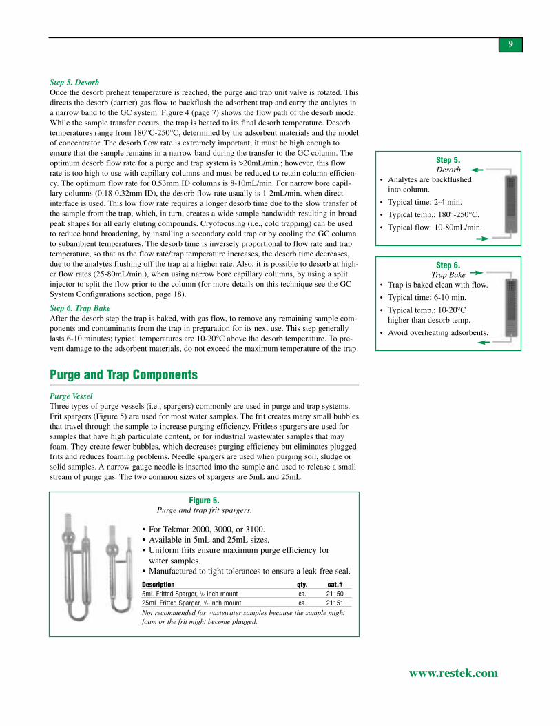
Figure 5.Purge and trap frit spargers.
9
www.restek.com
Purge and Trap ComponentsPurge VesselThree types of purge vessels (i.e., spargers) commonly are used in purge and trap systems.Frit spargers (Figure 5) are used for most water samples. The frit creates many small bubblesthat travel through the sample to increase purging efficiency. Fritless spargers are used forsamples that have high particulate content, or for industrial wastewater samples that mayfoam. They create fewer bubbles, which decreases purging efficiency but eliminates pluggedfrits and reduces foaming problems. Needle spargers are used when purging soil, sludge orsolid samples. A narrow gauge needle is inserted into the sample and used to release a smallstream of purge gas. The two common sizes of spargers are 5mL and 25mL.
Step 5.Desorb
• Analytes are backflushed into column.
• Typical time: 2-4 min.
• Typical temp.: 180°-250°C.
• Typical flow: 10-80mL/min.
Step 6.Trap Bake
• Trap is baked clean with flow.
• Typical time: 6-10 min.
• Typical temp.: 10-20°Chigher than desorb temp.
• Avoid overheating adsorbents.
Step 5. DesorbOnce the desorb preheat temperature is reached, the purge and trap unit valve is rotated. Thisdirects the desorb (carrier) gas flow to backflush the adsorbent trap and carry the analytes ina narrow band to the GC system. Figure 4 (page 7) shows the flow path of the desorb mode.While the sample transfer occurs, the trap is heated to its final desorb temperature. Desorbtemperatures range from 180°C-250°C, determined by the adsorbent materials and the modelof concentrator. The desorb flow rate is extremely important; it must be high enough toensure that the sample remains in a narrow band during the transfer to the GC column. Theoptimum desorb flow rate for a purge and trap system is >20mL/min.; however, this flowrate is too high to use with capillary columns and must be reduced to retain column efficien-cy. The optimum flow rate for 0.53mm ID columns is 8-10mL/min. For narrow bore capil-lary columns (0.18-0.32mm ID), the desorb flow rate usually is 1-2mL/min. when directinterface is used. This low flow rate requires a longer desorb time due to the slow transfer ofthe sample from the trap, which, in turn, creates a wide sample bandwidth resulting in broadpeak shapes for all early eluting compounds. Cryofocusing (i.e., cold trapping) can be usedto reduce band broadening, by installing a secondary cold trap or by cooling the GC columnto subambient temperatures. The desorb time is inversely proportional to flow rate and traptemperature, so that as the flow rate/trap temperature increases, the desorb time decreases,due to the analytes flushing off the trap at a higher rate. Also, it is possible to desorb at high-er flow rates (25-80mL/min.), when using narrow bore capillary columns, by using a splitinjector to split the flow prior to the column (for more details on this technique see the GCSystem Configurations section, page 18).
Step 6. Trap BakeAfter the desorb step the trap is baked, with gas flow, to remove any remaining sample com-ponents and contaminants from the trap in preparation for its next use. This step generallylasts 6-10 minutes; typical temperatures are 10-20°C above the desorb temperature. To pre-vent damage to the adsorbent materials, do not exceed the maximum temperature of the trap.
Not recommended for wastewater samples because the sample mightfoam or the frit might become plugged.
Description qty. cat.#5mL Fritted Sparger, 1/2-inch mount ea. 2115025mL Fritted Sparger, 1/2-inch mount ea. 21151
• For Tekmar 2000, 3000, or 3100.• Available in 5mL and 25mL sizes.• Uniform frits ensure maximum purge efficiency for
water samples.• Manufactured to tight tolerances to ensure a leak-free seal.

Figure 7.The flow paths for purging and desorbing are determined by the valve position.
10
www.restek.com
Figure 6.The 6-port automated switching valve (V) controls purge and desorb flow rates.
ValvesThe purge and desorb flows are controlled by an automated switching valve (Figure 6). Thevalve is contained in a heated compartment to prevent sample condensation inside. By rotat-ing the valve, the purge and desorb flow paths can be changed during the purge and trapsequence (Figure 7).
purgegas in
12
45 6
31
24
5 6
3
Tekmar 3100 in Desorb Mode
heated transfer line to GC
(4) 0.32mm ID fusedsilica transfer line(protected within
0.53mm ID Silcosteel® line)
(3) desorb/carrier gas
(2) from outlet end of trap
(1) vent
(5) frominlet endof trap
x
(6) purge
GC column
Valve positioned to purge sample onto trap.
trap
vent Valve position changed todesorb sample from trapand into capillary column.
purge gas in
gas in
GC column
trap
back
flus
hAdsorbent Materials and TrapsAdsorbent materials are used to trap the VOCs that have been purged from the sample. Theadsorbent must be able to retain compounds during the entire purging sequence and thenrapidly release them during the desorption step. Each adsorbent has a unique trapping capa-bility for a specific class or classes of compounds. Therefore, a trap may have several differ-ent beds of adsorbents. The weakest adsorbent material is placed at the inlet end of the trap,then the next strongest adsorbent, and so on. The more volatile compounds pass through theweaker adsorbents and are retained by the stronger adsorbents, while the less volatile com-pounds are retained on the weaker adsorbents and never reach the stronger adsorbents (fromwhich they would be difficult to desorb). Once the compounds are collected, the trap is rap-idly heated and backflushed with carrier gas to drive the sample components into the GCsystem. Ideally, the adsorbents in the trap retain polar and non-polar analytes without retain-ing water or methanol, efficiently release the trapped compounds onto the analytical column,and withstand the temperatures required to desorb (i.e., “bake off”) the higher molecularweight contaminants. A list of common traps used in purge and trap concentration can helpyou choose the best one for your application (Table II, page 13).
gas in
V
vent

11
www.restek.com
Adsorbent MaterialsTenax® Adsorbent (surface area: 50m2/g): Tenax® adsorbent is excellent for trapping non-polar compounds and is hydrophobic so it does not retain water; however, it does have somedisadvantages. Very volatile compounds are not retained well and must be trapped on astronger adsorbent material. In addition, polar compounds like alcohols are poorly retainedon this adsorbent. Tenax® adsorbent also has limited thermal stability; the 2,6-diphenyle-neoxide polymer thermally decomposes into toluene, benzene, and other aromatics. The par-ticles melt together and permanently adhere to the trap; this then restricts carrier gas flow.As the adsorbent degrades, there often is a loss in response for brominated compounds.
There are two grades of Tenax® adsorbent used as a trapping material: Tenax® GC andTenax® TA (Trapping Agent) adsorbents. Common background contaminants in Tenax® GCadsorbent include benzene and toluene. Tenax® TA adsorbent is a purer form and is morecommonly recommended for thermal desorption applications. The manufacturer’s recom-mended operating temperature is 230°C but, realistically, the material performs best whenkept below 200°C. Samples that contain organic acids can degrade Tenax® adsorbent. Thiseffect is more pronounced at higher temperatures; for longer trap life and better consistencydo not use traps containing this adsorbent at temperatures above 200°C.
Silica Gel (surface area: 200-800m2/g): Silica gel is a stronger adsorbent than Tenax®
adsorbent. Silica gel is commonly used in conjunction with Tenax® adsorbent as a trap forvolatile organic pollutants. It is an excellent trapping material for polar and highly volatilecompounds that are gases at room temperature; however, silica gel is extremely hydrophilicand will retain large amounts of water. Be aware that if a trap contains silica gel, dry purg-ing will not reduce the water content.
Coconut Charcoal (surface area: 900m2/g): Coconut charcoal is another strong adsorbentmaterial. It is commonly used in series after silica gel for trapping very volatile compoundsthat might break through the gel. Coconut charcoal is hydrophobic, and does not retain sig-nificant amounts of water. It does, however, trap carbon dioxide (CO2) purged from the sam-ple, and it has been reported that charcoal is a source of CO2, which can interfere with thequantitation of early-eluting compounds when using GC/MS systems.
Graphitized Carbon Black or Carbopack® Adsorbent (surface area: 10-100m2/g):Graphitized carbon black (GCB) is an alternative to Tenax® adsorbent. GCB is available inmany pore sizes and is effective in trapping volatile organics in the same range as Tenax®
adsorbent. GCB is hydrophobic and has excellent thermal stability, making it ideal for purgeand trap techniques. Highly volatile compounds are not retained well on GCB and must betrapped on stronger adsorbent materials such as carbon molecular sieves.
Carbon Molecular Sieves (surface area: 50-800m2/g): Carbon molecular sieves such asCarbosieve™-SIII are alternatives to silica gel and charcoal. High surface areas make thesematerials ideal for trapping highly volatile compounds. They are commonly used in seriesafter GCB because they retain compounds that break through the GCB. Carbon molecularsieves are hydrophobic and have excellent thermal stability.
Carboxen®-1000 Adsorbent (surface area: 1200m2/g): Carboxen®-1000 adsorbent is astrong adsorbent designed to be used as the innermost adsorbent bed in the trap (Figure 8,page 12). This material traps Freon® compounds, permanent gases, and light hydrocarbons.It has characteristics very similar to those of Carbosieve® S-III packing material. Carboxen®-1000 adsorbent is stable to temperatures of 300°C. Its only shortcoming is the adsorption ofCO2, which can interfere with early-eluting compounds.2 Carboxen®-1001 and Carboxen®-1002 are similar materials.
2. Mosesman, N.H., W.R. Betz, and S.D. Corman. "Alternate Trapping Materials for Purge-and-TrapAnalysis of Volatile Compounds." Proc.-Water Qual. Technol. Conf. Adv. Water Anal. Treat.. 14 (1987): 245-50.

Figure 8.Type “K” trap (VocarbTM 3000 trap)
showing the various layers.
6cm Carboxen 1000 (for gases)1cm Carboxen 1001(to prevent breakthrough)
12
www.restek.com
Choosing the Right Trap for Your AnalysisType “K” Trap (Vocarb™ 3000 Trap): The most effective trap on the market is theVocarb™ 3000 or type “K” trap (Figure 8). This trap has exceptional ability to retain highlyvolatile compounds like difluorodichloromethane with minimal bleed, activity, or break-down, yet it works well for trapping higher boiling compounds like naphthalene andtrichlorobenzene. The trap resists adsorption of water and methanol, and virtually eliminatesthe need for moisture control systems (MCS) and the dry purge step on the concentrator.Because this trap contains Carboxen™ 1000 adsorbent (described on page 11), which has asurface area of over 1200m2/g, a desorb temperature of 245°C is required when usingTekmar purge and trap instruments. For OI Analytical sample concentrators, such as theModel 4560, the desorb temperature should be 220°C or lower. The lower temperature willprevent overshooting the maximum temperature of the trap, which would damage the pack-ing materials (caused by the rapid trap heating rate, 800°C/min., of the OI system).3 Whenusing this trap be sure to verify performance. Non-linear response for chloromethane is asign of breakthrough and an indication that the trap must be changed. Another indication ofa defective “K” trap is loss in response for acrolein.
Type “J” Trap (BTEXTRAP™ Trap): The “J” trap is excellent for concentrating gasolinerange organics (GRO) because it retains less water and methanol compared to the “K” trap,and can withstand higher temperatures than the Tenax®/silica gel trap. Because many GROsamples have high concentrations of gasoline components, it is necessary to dilute the sam-ple in methanol, and this trap can accept a heavy sample load with percent levels ofmethanol while still passing continuing calibration check criteria. The disadvantage of the“J” trap is its limited ability to retain more polar analytes like the ethers and alcohols.Laboratories analyzing for tert-butyl alcohol will attain lower detection limits by using the“K” trap, compared to the “J” trap. For GRO samples containing methyl-tert-butyl ether(MTBE), trap selection will depend on the sample matrix. When analyzing highly contami-nated soils for MTBE, it is best to use the “J” trap. For cleaner samples, the “K” trap pro-vides better sensitivity.
Type “B” Trap (Tenax®/Silica Gel Traps): Tenax®/silica gel traps are used for a variety ofVOC methods. These traps exhibit better recoveries of polar analytes than the “K” trap, butthe silica gel layer adsorbs water, methanol, and carbon dioxide. The Tenax®/silica gel trapalso has better lot-to-lot reproducibility compared to the “K” or “I” traps. For laboratoriesthat are not trying to achieve MDLs for gaseous VOCs at concentrations above 10ppb, thesetraps will work well. To achieve detection limits for gases at concentrations below 10ppb,the lower water and methanol retention of the “K” trap is recommended.
Type “F” Trap (OV®-1 /Tenax®/Silica Gel Traps): Although these traps are recommended inmany EPA methods, they exhibit more bleed and activity than the Tenax®/silica gel trap,with no significant improvement in performance. This suggests the bleed originates from theOV-1 (methyl silicone) material.4 Therefore, laboratories wishing to adhere more closely tothe EPA Method Protocol should choose Tenex®/silica gel traps without OV®-1.
Type “I” trap (Vocarb 4000™): The “I” trap is used for increased response for less volatilecompounds such as the chloronaphthalenes and methylnaphthalenes. Generally, it is usedonly for applications involving analytes of larger molecular size and is not the first choicefor ketones or alcohols. Common desorb times of two to four minutes should be increasedwith the “I” trap, to optimize sensitivity for compounds having high boiling points.
10cm Carbopack B(for mid- and later-eluting volatiles)
Purge Flow
Vent
3. OI Analytical, “Volatile Organics Analysis: Building a State-of-the-Art Purge and Trap GC/MS system” Application Note 02971294.
4. OI Analytical, “Proper Trap Selection for the OI Analytical Model 4460A Purge and Trap SampleConcentrator” Application Note 12851098.

13
www.restek.com
Moisture Control Systems—Water and Methanol Management Water and methanol can cause the biggest problems in purge and trap concentration. Duringthe desorb step, water and methanol that accumulated on the trap are released into the chro-matographic system. As much as 10µL of water can accumulate on a trap containing silicagel during a purge; this expands to 12mL of water vapor during desorption.5 Interferencecaused by excess water is a problem during detection. For example, water vapor passingthrough a PID can cause a negative dip in the baseline. Water also can saturate a PID,decreasing its sensitivity and interfering with the identification of compounds that coelutewith water. Detector saturation also can occur with MS systems. Although the lower end ofthe scan range typically is adjusted above the molecular weight of water, interference canstill occur. If the water plug is very large, the peaks for analytes that elute in thewater/methanol region will broaden and sensitivity will be reduced.
In similar fashion, methanol also causes interferences with target analytes. The PID gives apositive signal for methanol as a broad, flat-topped peak that usually interferes with 2-methylpentane, 3-methylpentane, and vinyl chloride. Adjusting the MS scan range to startabove 35amu can minimize the effects of methanol (mass/charge ratio of 31amu). Whenusing an Rtx®-VMS column, or a cyanopropylphenyl “624”-type column, methanol andchloroethane will elute simultaneously. This can affect sensitivity and linearity forchloroethane (Figure 9). When using a “502.2” phase column, methanol coelutes with bro-momethane. Spiking higher concentration intermediate standards into the purge vessel orautosampler vials can minimize methanol interference. Also note that an increase inmethanol added to the purge standard also inevitably increases the amount of water thatpurges into the system.
In recent years, much work has gone into developing hydrophobic adsorbents that minimizewater collection on the trap. Extensive studies recommend incorporating a dry purge cycleto remove water from the trap prior to desorption. Current designs of purge and trap systemshave added features to eliminate water prior to delivering the sample to the chromatograph-ic system. Moisture control systems (MCS) remove water by condensation, prior to the des-orb step. Such systems typically are composed of a piece of metal tubing that is heated dur-ing purge and then cooled to 30°C. The sample, desorbed from the heated trap, travelsthrough the MCS, where a large portion of the water is condensed from the saturated carriergas. These systems are very effective for GC methods that do not have polar/active com-pounds, such as ketones, in the analyte list. An older purge and trap system that does nothave an MCS can be retrofitted with one. Restek offers an MCS bypass line for Tekmar3000 and 3100 purge and trap concentrators, to increase response and maintain linearity forketones, alcohols, and acetates (Figure 10, page 14). When analyzing samples for ketones orother polar compounds, the MCS should be bypassed to maintain linear calibration for thesecompounds.
Table II.Compositions and characteristics of common types of traps.
Description Trap Designation Dry Purge Preheat (°C) Desorb (°C) Bake (°C)24cmTenax® A yes 175 180 20015cm Tenax®/8cm silica gel B no 175 180 2008cm Tenax®/7.7cm silica gel/7.7cm charcoal C no 175 180 20016cm Tenax®/7.7cm charcoal D yes 175 180 2001cm OV®-1/7.7cm Tenax®/7.7cm silica gel/ E no 175 180 200
7.7cm charcoal1cm OV®-1/15cm Tenax®/7.7cm silica gel F no 175 180 2001cm OV®-1/ 23cm Tenax® G yes 245 250 2607.6cm Carbopack® B/1.3cm Carbosieve® S-III H yes 245 250 2608.5cm Carbopack® C/10cm Carbopack® B/ I (Vocarb™ 4000) yes 245 250 260
6cm Carboxen® 1000/1cm Carboxen® 10017.7cm Carbopack® C/1.2cm Carbopack® B J (BTEXTRAP™) yes 245 250 26010cm Carbopack® B/6cm Carboxen® 1000/ K (Vocarb™ 3000) yes 245 250 260
1cm Carboxen® 1001
5. OI Analytical, “OI Analytical Model 4560 Sample Concentrator Rapid Trap Heating”Application Note 04521297.

14
www.restek.com
1.90 2.00 2.10 2.20 2.30 2.40 2.50 2.60 2.70 2.80 2.90 3.00 3.10 3.20 3.30 3.40 3.50 3.60 3.70
Figure 9.MS scan rate adjusted to detect methanol and show the region
where methanol elutes from an Rtx®-VMS column.
Figure 10.An MCS bypass line can increase response and maintain
linearity for ketones, alcohols, and acetates. disconnectedMCS line
top of trap
Transfer LineOnce the sample is desorbed from the trap, it travels through the heated transfer line to theGC. This line can be made of nickel, fused silica, or Silcosteel®-treated tubing. A heatingjacket surrounds the transfer line to keep it between 120-125°C, which prevents water andanalyte condensation in the line. For direct connection, we recommend matching the insidediameter of the transfer line to the inside diameter of the capillary GC column, or use of tub-ing of a slightly smaller inner diameter than the capillary column. This helps minimize bandbroadening and poor peak symmetry for sample components. Because transfer lines can be asource of active sites, use deactivated fused silica or Silcosteel®-treated tubing to reduce ana-lyte adsorption. When using a fused silica transfer line, insert the line into a metal tubebefore installing it into the heated jacket. This will protect the fused silica tubing from nicksand scratches that could cause the line to break. Be sure to use the correct Valco® ferrules tominimize dead volume (see Direct Connection, page 20).
1
2
3
4
5
1. difluorodichloromethane2. chloromethane3. vinyl chloride4. bromomethane5. chloroethane6. trichlorofluoromethane
EPA Method 8260, Rtx®-VMS column, 30m, 0.25mm ID,1.40µm (cat.# 19915)Carrier gas: 1.3mL/min. @ constant flowGC: HP 6890Detector: HP 5973 MSDOven temp.: 45°C (ISD)MS scan range: 29-260amu methanol
CO2
MCS
min.
bypass line
Moisture Control Bypass Line forTekmar 3000 Purge & Trap• Increases response for ketones, alcohols, and acetates.• Suitable for US EPA Methods 8260, 524.2, and OLM4.1.• Silcosteel® tubing for increased inertness.• Easily attaches in minutes.
Description qty. cat.#Moisture Control Bypass Line ea. 21035
1.90 2.00 2.10 2.20 2.30 2.40 2.50 2.60 2.70 2.80 2.90 3.00 3.10 3.20 3.30 3.40 3.50 3.60 3.70
6
15
www.restek.com
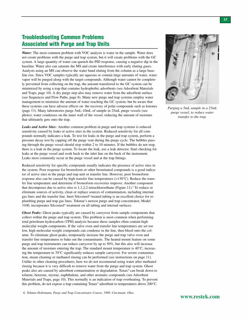
Troubleshooting Common Problems Associated with Purge and Trap UnitsWater: The most common problem with VOC analysis is water in the sample. Water doesnot create problems with the purge and trap system, but it will create problems with the GCsystem. A large quantity of water can quench the PID response, causing a negative dip in thebaseline. Water also can saturate the MS and create interference with early eluting gases.Analysts using an MS can observe the water band eluting from the column as a large base-line rise. Since VOC samples typically are aqueous or contain large amounts of water, watervapor will be purged along with the target compounds. Although water cannot be complete-ly prevented from collecting on the trap, the amount transferred to the GC system can beminimized by using a trap that contains hydrophobic adsorbents (see Adsorbent Materialsand Traps, page 10). A dry purge step also may remove water from the adsorbent surface(see Sequences and Flow Paths, page 8). Many new purge and trap systems employ watermanagement to minimize the amount of water reaching the GC system, but be aware thatthese systems can have adverse effects on the recovery of polar compounds such as ketones(page 13). Many laboratories purge 5mL-10mL of sample in 25mL purge vessels (seephoto); water condenses on the inner wall of the vessel, reducing the amount of moisturethat ultimately gets onto the trap.
Leaks and Active Sites: Another common problem in purge and trap systems is reducedsensitivity caused by leaks or active sites in the system. Reduced sensitivity for all com-pounds normally indicates a leak. To test for leaks in the purge and trap system, perform apressure decay test by capping off the purge vent during the purge cycle. The bubbles pass-ing through the purge vessel should stop within 2 to 10 minutes. If the bubbles do not stop,there is a leak in the purge system. To locate the leak, use a leak detector. Start checking forleaks at the purge vessel and work back to the inlet line on the back of the instrument.Leaks most commonly occur at the purge vessel and at the trap fittings.
Reduced sensitivity for specific compounds usually indicates the presence of active sites inthe system. Poor response for bromoform or other brominated compounds is a good indica-tor of active sites in the purge and trap unit or transfer line. However, poor bromoformresponse also can be caused by high transfer line temperatures (>130°C). Reduce the trans-fer line temperature and determine if bromoform recoveries improve. Another componentthat decomposes due to active sites is 1,1,2,2-tetrachloroethane (Figure 11).6 To reduce oreliminate sources of activity, clean or replace sources of contamination, including internalgas lines and the transfer line. Inert Silcosteel®-treated tubing is an excellent choice for re-plumbing purge and trap gas lines. Tekmar’s newest purge and trap concentrator, Model3100, incorporates Silcosteel® treatment on all tubing and internal surfaces.
Ghost Peaks: Ghost peaks typically are caused by carryover from sample components thatcollect within the purge and trap system. This problem is most common when performingtotal petroleum hydrocarbon (TPH) analysis because these samples often contain highmolecular weight components. If the valve oven and transfer line temperatures are set toolow, high molecular weight compounds can condense in the line, then bleed onto the col-umn. To eliminate ghost peaks, temporarily increase the purge and trap valve oven andtransfer line temperatures to bake out the contaminants. The heated mount feature on somepurge and trap instruments can reduce carryover by up to 50%, but this also will increasethe amount of moisture entering the trap. The standard mount temperature is 40°C; increas-ing the temperature to 70°C significantly reduces sample carryover. For severe contamina-tion, steam cleaning or methanol rinsing can be performed (see instructions on page 11).Unlike in other cleaning procedures, here we do not recommend using water after methanolrinsing because it is very difficult to remove water from the purge and trap system. Ghostpeaks also are caused by adsorbent contamination or degradation. Tenax® can break down totoluene, benzene, styrene, naphthalene, and other aromatic compounds (see AdsorbentMaterials and Traps, page 10). This normally is an indication of trap overheating. To preventthis problem, do not expose a trap containing Tenax® adsorbent to temperatures above 200°C.
Purging a 5mL sample in a 25mLpurge vessel, to reduce water
transfer to the trap.
6. Tekmar-Dohrmann, Purge and Trap Concentrator Course, 1989. Cincinnati, Ohio.

20m, 0.18mm ID, 1.0µm Rtx®-502.2 column (cat.# 40914), 4ppb of VOA standards.Oven temp.: 35°C (hold 5 min.) to 180°C @ 6°C/min.
to 210°C @ 20°C/min. (hold 5 min.)Inj. / det. temp.: 100°C / 280°CLinear velocity: 20cm/sec. set @ 35°CPurge & trap: Tekmar 3000Purge: 11 min.Trap pressure control: 6psiDesorb preheat: 250°CDesorb time: 2 min.Detector: MSSplit ratio: 40:1Scan range: 35-260AMUTrap: Vocarb™ 3000Desorb temp.: 260°CDesorb flow rate: 20mL/min.
16
www.restek.com
Figure 11.No measurable response for bromoform (9), combined with a greatly diminished response
for 1,1,2,2-tetrachloroethane (10), strongly indicates a contaminated transfer line.
Instructions for Cleaning Purge and Trap Concentrators We developed these instructions using Tekmar LSC 2000 and 3000 concentrators. Alwaysremember to use safety glasses when working in the laboratory.
1. Keep the instrument power on and turn the line heaters off. Set all temperatures to the offposition. WAIT UNTIL HEATED ZONES HAVE COOLED.
2. Make sure the unit is in standby mode.
3. Disconnect the purge and trap vessel.
4. Flush methanol into the area where the top of the trap attaches, using a 5mL syringewithout a needle (i.e., a Luer-lock syringe - see photo). This is the area where the purgevessel attaches to the purge and trap. You should see methanol coming out of the mount.
5. Clean the mount, using a tissue. The mount is either nickel- or gold-plated, so be carefulnot to scratch the surface. If you cannot clean the mount, it may need to be replaced.
6. Clean the purge vessel with methanol, then with ultra-pure water. Do not use soap. Youmay use a brush.
7. Increase purge and trap temperatures to normal operating conditions and hold for twohours, with no trap or purge vessel installed.
8. Install an empty trap. Do not use an old trap with the packing removed; particles of trap-ping material may end up in the concentrator. If an empty trap is not available, refer to thenext paragraph. With the empty trap in place, attach all lines, including the line to thepurge vessel. Desorb for at least one hour with the transfer line disconnected from the col-umn. This will help to drive any methanol remaining from step 6 out of the system.
If you do not have an empty trap, disconnect the transfer line from the column, connectthe purge vessel and all lines, and install an old trap. Desorb for one hour.
9. Install and condition a new trap and run blanks until a clean baseline is achieved.
If you are still having activity problems after following this procedure, please contact theRestek Technical Service Team via email at [email protected] or via phone at 800-356-1688 or 814-353-1300, ext. 4.
Flushing the trap attachment area withmethanol. Repeat several times.
20
6
11
19
21
22
23
24
min. 20
7
c-gram #216
2,3
4,5
12,13
8
10
1
14,15
18
16
25
17
Permission to publish this chromatogramgranted by Anne Williams, Tekmar Company.
1. chlorobenzene2. ethylbenzene3. 1,1,1,2-tetrachloroethane4. m-xylene5. p-xylene6. o-xylene7. styrene8. isopropylbenzene9. bromoform (not detected)10. 1,1,2,2-tetrachloroethane11. 1,2,3-trichloropropane12. propylbenzene
13. bromobenzene14. 1,3,5-trimethylbenzene15. 2-chlorotoluene16. 4-chlorotoluene17. tert-butylbenzene18. 1,2,4-trimethylbenzene19. sec-butylbenzene20. p-isopropyltoluene21. 1,3-dichlorobenzene22. 1,4-dichlorobenzene23. n-butylbenzene24. 1,2-dichlorobenzene
EPA UpdateThe US EPA promulgated update III of TestMethods for Evaluating Solid Waste (SW-846). This 1997 update deleted the previousEPA purge and trap Method 5030A, “SamplePreparation of Volatile Organic Compounds forPurge and Trap Analysis” and replaced it withMethod 5035, “Closed System Purge and Trapand Extraction for Volatile Organics in Soil andWaste Samples.” Method 5035 involvesextensive fieldwork and raises MDLs for soilsamples; however, accuracy is improved.
Previously, soil samples were collected usingPTFE-lined screw-cap containers and storedat 4°C, with a 14-day maximum holding time.Once the samples were in the laboratory, 5galiquots of soil were added to 5mL of reverseosmosis (RO) water. The volatiles in thesesamples exit the soil matrix and leak from thecontainer. Method 5035 requires samples tobe collected and preserved in the field at thetime of sampling, using methanol and a stir-bar. Volatiles dissolved in the methanol areless likely to escape. The seal is not brokenuntil the time of analysis, thus minimizinganalyte loss through evaporative mechanisms.Sodium bisulfate is used to prevent biodegra-dation of VOCs. Unlike HCl preservation, sodi-um bisulfate does not break down 2-chloroethyl-vinyl-ether. This greatly improvesthe accuracy of analytical results from soilsamples because evaporative loss occursalmost immediately in soils that are not pre-served in methanol. Disadvantages include thehigher detection limits and the problems asso-ciated with purging higher percentages ofmethanol.

17
www.restek.com
Broad Peaks: Peak broadening is another problem often experienced when analyzing VOCsby purge and trap methods. Broad peaks are caused either by poor sample transfer from thepurge and trap to the GC or by dead volume within either system. Broad peaks frequentlyresult from dead volume in the connection between the purge and trap unit and the GC sys-tem. (See pages 18-21 for connection methods.) Because trap desorption is a relatively slowprocess, the sample band transferred to the GC can be very wide. To reduce this bandwidth,the sample must be transferred quickly and/or refocused at the inlet of the GC columnthrough a secondary cold trapping technique such as cryofocusing or subambient cooling.The transfer time can be reduced by using the desorb preheat feature. During this step, thetrap is heated to 5°C below the desorption temperature, and the valve is positioned so noflow passes through the trap. This helps the compounds trapped on the adsorbents to rapidlymigrate from the trap when backflushing begins.
The desorb flow rate also will affect the bandwidth. If the desorb flow is too low (<9mL/min.),the band becomes broad (Figure 12) and must be refocused at the column inlet. If faster flowrates are used (>9mL/min.) in conjunction with long, thick-film columns, the bandwidth can bereduced enough so that secondary trapping is not required. Ideally, desorbing at a flow rate of20-30mL/min. yields a very narrow bandwidth. However, when using narrow bore columns, itmight be necessary to split the flow at the injection port to maintain column efficiency.
Foaming Samples: Analysts deal with foaming samples in two primary ways: by dilution orby addition of an anti-foaming agent. Diluting the sample compromises the detection limit,but in the end may save instrument downtime. Anti-foaming agents such as polydimethyl-siloxane and silicon dioxide methylcellulose are designed to reduce foaming of surfactants ina liquid matrix. These are effective at preventing a sample from foaming, but they generallyproduce artifact peaks that can interfere with the target analytes. An anti-foam blank must berun prior to samples to determine the contribution of artifact peaks from the anti-foamingagent. If dilution or anti-foaming agents do not reduce foaming or if samples have not beenscreened for surfactants, use a 5 or 10mL sample in a 25mL purge vessel to prevent the bub-bles from entering the fittings and, ultimately, the trap. If you are running an unattendedautosampler, you can insert a plug of deactivated fused silica or glass wool into the top ofthe purge vessel to prevent foam from entering the purge and trap lines. If all else fails con-sider switching to a fritless sparge tube and increasing the purge time to effectively removethe volatile analytes.
3.50min. 4.50 5.50 6.50 7.50 8.50 9.50 10.50 11.50
5,6
43
2
1
Figure 12.A low desorb flow can produce tailing peaks, as in this example, desorbed at 9mL/min.
1. benzene2. α,α,α-trifluorotoluene (SS)3. toluene4. ethylbenzene5. m-xylene6. p-xylene7. o-xylene
EPA Method 8020, Rtx®-5Sil MS column, 40m, 0.45mm ID, 1.5µm (cat. #12798)Carrier gas: 9mL/min. @ constant pressureGC: Finnigan 9001Detector: FIDOven temp.: 40°C (hold 2 min.)
85°C @ 4°C/min. (hold 1 min.) to 225°C @ 40°C/min. (hold 2 min.)
7
Wastewater samples commonlycontain surfactants and othermaterial that can contaminate
the concentrator.

18
www.restek.com
Figure 13.Plumbing a purge and trap interface to a GC injection port allows flow adjustment via theGC flow controller. This is the most common way of analyzing volatile compounds by MS
because the flow can be split, allowing 1mL/min. into the MS source.
GC System ConfigurationsWide-bore Systems (0.45mm ID and 0.53mm ID columns)Wide-bore capillary columns are operated at faster flow rates than narrow-bore columns, andcan be connected directly to the purge and trap system with a 10mL/min. desorb flow. Wide-bore columns used for VOCs analyses usually are coated with a thick film of stationaryphase to increase retention and separation of the highly volatile analytes (e.g.,chloromethane and vinyl chloride, bromomethane and chloroethane), or other closely-elutingsample components.
Wide-bore columns range from 30-105 meters in length. A longer column can refocus early-eluting volatile compounds and greatly improve separation of the gases (see Applications,page 37). Shorter columns require sub-ambient cooling for separating the gases; this increas-es the cost of the analysis and adds laboratory time associated with handling tanks of liquidnitrogen. For best overall results, we recommend using a 75m, 0.45mm ID capillary columnfor analyzing the volatile compounds listed in US EPA Methods 502.2 and 8021B (seeApplications, page 37).
Resolution of the early-eluting gaseous analytes increases significantly with a decrease intemperature. Use a starting temperature of 35°C-50°C, depending on the target list and thepurge and trap conditions (see Applications, page 37). A longer column can be used toincrease the pressure within the column, which, in turn, will increase the solubility of theanalytes in the stationary phase. Using optimized temperature programs and narrower band-widths, reasonably fast analysis times can be achieved (see page 37). However, the higherflow rates through wide-bore columns prevent the analyst from directly connecting the col-umn to the vacuum system of an MS. A jet separator or open split interface must be used toreduce the amount of carrier gas flowing into the MS (see Figure 31, page 32).
The method for connecting a purge and trap transfer line to a wide-bore GC column shouldbe carefully considered. The three connection methods are: 1) through the existing GC injec-tion port; 2) using a low volume injector; and 3) with a direct column connection. Thesealternatives are described below.
Injection Port Connection: In this connection option, the purge and trap transfer line is con-nected to the GC injection port that accepts the carrier gas line. The carrier gas line is cutclose to the injection port body and a deactivated union (e.g., cat.# 20510, see our catalog) isused to connect the purge and trap transfer line to the injection port (Figures 13 through 16).This allows the analyst to make manual injections when troubleshooting, and to inject bro-mofluorobenzene when tuning the MS in accordance with EPA methods. The injection portcan be a source of dead volume, however. Dead volume causes band broadening, resulting inpoor peak shape and loss of resolution for the most volatile target compounds. The severityof the problem is determined by the inside diameter of the injection port liner and the totaldesorb flow through the port. To reduce the dead volume in the injection port, use a 1mm IDsplit liner (e.g., cat. #20972; see products section). If the injection port is designed for
Line From P&T
Septum Purge Line
Split Line
Description qty. cat.#Vu-Tight® DI Liner ea. 20342Vu-Tight® DI Liner 5-pk. 20343Vu-Tight® DI Liner 25-pk. 20344
Vu-Tight® Direct Injection Liner• Visually observe the Press-
Tight® connection betweenthe column end and liner.
• 1/4-Inch OD: accepts 0.32 or 0.53mm ID capillary column (column OD from0.5mm to 0.8mm).
• Slotted top prevents obstruc-tion of carrier gas flow.
• Two designs available.*• Operate in the direct injection mode.• Can easily be packed with wool for
dirty samples.
* Refer to our catalog for information aboutCyclo Vu-Tight® liners, for use with dirty samples.

Figure 14.Configuring your GC is simple! Prepare the lines by cutting them as shown. (Agilent 6880)
19
www.restek.com
Septum Purge
Attaches to Electronic PressureControl (EPC) Unit of
Chromatograph
Split Line
To P&TCarrier Gas
Cut Lines, Add Brass Nuts
Figure 15.Carrier gas flow is adjusted through the injection port regulator. Carrier gas sweeps
analytes from the trap, through the transfer line, onto the column. (Tekmar 3100)
Figure 16.Reconnect the weldment lines to the GC and check for leaks.
Be sure to set up the lines correctly. (Agilent 6890)
From GCCarrier Gas
Heated TransferLine (To GC
Injection Port)
Septum Purge
Split Vent
Gas Lines
packed columns, we recommend using a Vu-Tight® inlet liner (cat. #20342, page 18). Thewide-bore capillary column is sealed into the tapered restriction in the liner, ensuring directtransfer of the sample to the column. In addition, the Vu-Tight® inlet liner allows visualinspection of the column-to-liner seal.
Low-Volume Injectors: A low-volume injector (LVI) will reduce dead volume, yet allowlimited manual injections. Such a system can be used to convert a packed column or a capil-lary split/splitless injection port for purge and trap applications. The internal volume of theinjector is significantly reduced, compared to a conventional injection port, which improvessample transfer from the purge and trap system. The purge and trap transfer line is connectedto the LVI, and the wide-bore column is connected at the base of the injector. A septum in theLVI allows manual injections if needed.
Low Volume Injectors
Description cat.#Low-Volume Injector for AgilentSplit/Splitless GC Inlets 21692Low-Volume Injector for Agilent5890 Septum Packed Purge Port 21698Low-Volume Injector for VarianSplit/Splitless GC Inlets 21693
For descriptions of low-volume injectors,see page 63.

20
www.restek.com
Figure 18.Connect the fused silica line directly to the 6-port valve. Notice a small (5mm)
septum helps determine how far the column is inserted into the valve, preventing breakageat the column end that could allow shards of fused silica to enter the valve.
Figure 17.A dual-column configuration splits the sample equally between separate detector systems.
Direct ConnectionA union between the purge and trap transfer line and the capillary column bypasses theinjection port, eliminating the problems associated with the injection port: loss of samplethrough the septum purge, adsorption of active compounds, bleed from Viton® O-rings orseptum, and — most important — dead volume. Two direct connections are describedbelow. The disadvantage of a direct connection is it eliminates the ability to make manualinjections when attempting to isolate a chromatographic problem. Therefore, this connectiontechnique works best for experienced analysts and for instruments that undergo regularmaintenance.
Metal Transfer Line: This is the easier of the two direct connection methods. Using thetransfer line provided by the instrument manufacturer and an MXT® low dead volume con-nector (cat.# 20394, see our catalog), connect the trap to the capillary column. This configu-ration significantly improves peak shape, compared to injection port connections, especiallywith an electrolytic conductivity detector (ELCD).
Fused Silica Transfer Line: A fused silica transfer line further reduces dead volume, rela-tive to the original equipment line. We recommend using Siltek® fused silica tubing for VOCor other sensitive analyses because it is not affected by moisture and is inert to active com-pounds. To configure the line, disconnect the metal transfer line from the Valco® six-portvalve, then remove the metal ferrule and 1/16" nut by cutting the end of the tubing. Whilewearing insulated gloves, heat the line to 200°C to melt the glue that holds the line in place,then use pliers to pull the line out of the heater jacket. Cool the line, install a piece of metaltubing (cat. #21503, see our catalog) inside the line, then install the Siltek®-treated fused sili-ca transfer line within the metal tubing (cat. #10027, page 63). The metal tubing will preventthe transfer line from being scratched or broken. Base the ID of the metal tubing on the ODof the transfer line: 0.02" ID for a 0.25 or 0.32mm ID fused silica line, 0.30" ID for a 0.45or 0.53mm ID line. In turn, base the ID of the transfer line on the ID of the analytical col-umn; we recommend using a transfer line with an ID equal to or slightly smaller than that ofthe column. A transfer line with an ID slightly smaller than that of the column will increasebackpressure, enhancing the resolution of early-eluting compounds. Use a Press-Tight® con-nector (cat. #20400 or 20403, page 20) to connect the fused silica transfer line to the analyti-cal column (Figure 17). Use the correct ferrule for connecting the column to the 6-port valve(Figure 18); we recommend a one-piece fused silica adaptor (cat. #20137, page 64).
Angled “Y”Press-Tight®
Connector
Septum
Fused Silica
MXT® Metal Tubing(used to protect fused
silica column)
Universal Press-Tight®
Connectors
Description cat.#Universal Press-Tight® Connectors, 5-pk. 20400Universal Press-Tight® Connectors, 25-pk. 20401Universal Press-Tight® Connectors, 100-pk. 20402Universal Angled “Y” Press-Tight®
Connector, ea. 20403Universal Angled “Y” Press-Tight®
Connectors, 3-pk. 20404
For additional connectors, see page 64.

21
www.restek.com
Narrow-bore Systems (0.18mm ID - 0.32mm ID columns)Narrow-bore columns (0.18mm ID-0.32mm ID) offer higher resolution, compared to0.45mm ID or 0.53mm ID columns. Because these columns typically are operated at lowerflow rates, they are not compatible with the fast desorb flow rates from common purge andtrap systems. Splitting the sample at the injection port or cryofocusing (i.e., secondary trap-ping) will provide compatibility and help focus the sample at the column inlet.
Splitting the Sample: Many environmental laboratories analyzing VOCs by GC/MS use nar-row-bore capillary columns and split the sample at the injection port. Higher sensitivity iontrap GC/MS systems (e.g., Varian Saturn 2000™ and Thermo Finnigan GCQplus™ sys-tems) 7 and recently developed quadrapole MS systems (e.g., the Agilent 5973 system) allowhigh split ratios in the injection port while maintaining sensitivity adequate to meet therequirements of EPA Method 524.2.8 Older quadrapole GC/MS systems require an increasein purge volume (25mL) to compensate for the sample lost due to splitting.
Using a standard split/splitless injection port to split the desorb flow allows a higher desorbflow rate while maintaining a lower column flow. With this technique, the trap is desorbedat a flow rate of 10-60mL/min. and the column flow rate is adjusted to 1.0-1.3mL/min.,which is compatible with the vacuum system of an MS. The remaining flow exits throughthe split vent. The faster desorb flow rate produces a narrow sample bandwidth which, whencombined with the high efficiency of a narrow-bore column, allows high split ratios withoutsignificant loss in sensitivity.8 Surprisingly, a 1:20 split ratio provides more sensitivity than a1:10 split ratio, because the higher flow from the trap focuses the target compounds moreefficiently.
Cryofocusing (secondary trapping): A cryofocusing unit refocuses the volatile compoundsat the inlet of the narrow-bore column. This allows the trap to be desorbed at only 1-2mL/min., while improving peak shape and resolution by reducing sample bandwidth.Cryofocusing takes place on a short length of deactivated, uncoated, fused silica tubing thatis cooled to -160°C using liquid nitrogen. To increase retention for very volatile gases, orwhen analyzing Freon® compounds, use tubing coated with a thick film of stationary phase.
While cryofocusing greatly improves peak shapes from narrow-bore columns, the approachconsumes large amounts of liquid nitrogen, increasing operating expenses and requiring liq-uid nitrogen tanks in the lab. If the liquid nitrogen tank empties in the middle of a samplesequence, there can be significant downtime before the tank is replaced.
Capillary Column PhasesMany capillary columns have been designed for the analysis of VOCs. Column selectionnormally is based on the analytical method (e.g., US EPA method), compound list, anddetection system used. This section serves as an overview of the different phases used forVOC analyses. See the Applications section (page 37) for examples of GC and GC/MS sep-arations under specific conditions.
The first columns used for analyzing volatiles were based on diphenyl/dimethyl polysilox-ane stationary phases. These include VOCOL®, Rtx®-Volatiles, HP®-VOC, and Rtx®-502.2columns. The main advantages of these phases are their resistance to oxidative breakdownand their lower bleed, compared to cyanopropylphenyl polysiloxane (i.e., “624”) phases.The major drawback of diphenyl/dimethyl polysiloxane phases is the incomplete resolutionof bromomethane and chloroethane. Many environmental laboratories still use thesecolumns, especially when analyzing samples for a limited set of compounds.
7. Jessie Crockett Butler, Meredith Conoley, "Analysis of Volatile Organics in Solid Wastes, Soils, andWater Using a Split Injection and the Polaris Q Ion Trap GC/MS." Application Note AN9167.Thermo Finnigan, GC and GC/MS Division, Austin, TX.
8. D.R. Decker, J.J. Harland, and M.J. Feeney, "Comparison of Detection Limits and Analysis TimeUsing Wide and Narrow Bore Capillary Columns for Purge-and-Trap GC/MS Analyses." OIAnalytical. Application Note 02850896.

22
www.restek.com
Another type of column used for VOC analysis is based on cyanopropylphenyl/dimethylpropyl polysiloxane phases, commonly known as the “624” phases. The Rtx®-624 column isdesigned for EPA Method 624, but also performs well for Methods 524.2, Revision IV, and8260. The main advantage of the Rtx®-624 column is the complete separation of the highlyvolatile gases, including dichlorodifluoromethane, chloromethane, vinyl chloride,chloroethane, and bromomethane.
More recently, the Rtx®-VRX column was developed, using computer-assisted stationaryphase design (CASPD), to address the expanded list of compounds in EPA Methods 8021and 502.2. This unique column improves resolution and reduces overall analysis time com-pared to traditional columns. Like the Rtx®-624 column, the Rtx®-VRX column providesexcellent separation of the highly volatile gases. Its only disadvantage is poor resolution ofthe most common trihalomethanes (THMs), chloroform and bromodichloromethane, fromother target analytes. These analytes are frequently found in chlorinated drinking water sam-ples. While the Rtx®-VRX column has been used for MS methods with favorable results,because of this poor resolution it is not recommended for drinking water analysis usingPID/ELCD detection.
The most recent innovations for VOC analysis have been the development of the Rtx®-VGCand Rtx®-VMS columns. These columns also were designed using CASPD. Designed forPID/ELCD analyses, the Rtx®-VGC column resolves all compounds listed in EPA Methods502.2 and 8021, with >80% resolution of each of the four trihalomethanes from the othertarget compounds, >30% resolution between 2-chlorotoluene/1,1,2,2-tetrachloroethane, and>60% resolution of all other volatile compounds in the two EPA methods. The columnresolves the gases and early-eluting compounds well enough that the GC oven program canbe started at 50°C.
The Rtx®-VMS column was designed to address the increasing number of analytes listed inEPA Method 8260, and also is a good choice for separating compounds listed in EPAMethod 524.2, revision IV. The major difference between the Rtx®-VMS phase and otherssuch as “502.2,” “624,” or “VRX” is its overall selectivity and the distance between mem-bers of isomeric pairs, like 2-/4-chlorotoluene. A faster final oven ramp rate is possiblebecause these compounds elute farther apart on the Rtx®-VMS phase, eliminating partial co-elutions that would interfere with quantification. This column offers excellent separation ofEPA Method 8260B compounds in less than 18 minutes - the normal cycle time for a purgeand trap system. Using the EPA-suggested surrogates the analysis time can be less than 10minutes with a narrow bore column. Even faster analyses are possible if you replace theinternal standard chlorobenzene-d5 with another compound, such as 4-bromofluorobenzene.Sub-10-minute analysis times allow you to connect two purge & trap units to one GC/MSinstrument, significantly increasing sample throughput (see page 37).
Metal ColumnsIn addition to the standard fused silica versions of the analytical columns discussed above,metal MXT® columns coated with the same stationary phases also are available from Restek.To eliminate the activity problems associated with metal tubing, we make these columnsfrom Silcosteel®-treated stainless steel tubing, assuring excellent inertness. Because thesecolumns are much more durable than fused silica columns, and can be coiled to less than 5-inch diameters, they are ideal for portable GC applications. Their durability makes them apopular choice for teaching laboratories at colleges and universities. Analyte resolution onMXT® columns is similar to that on fused silica columns.

23
www.restek.com
Detection SystemsVOCs can be analyzed using a variety of detection systems, including GC/MS, GC/PID, andGC/ELCD. Here, we discuss consequences of using each of these systems, and present tipsfor maintenance and troubleshooting.
Column ConfigurationsSingle Column: Environmental engineers characterize a contaminated site using MS ordual-column GC, or they might monitor the site solely with single-column GC methods.Injections of standards on a single column, delivered to the detector, can provide tentativeidentification and quantification. Retention times for analytes listed in a given method areestablished by injecting a check standard containing all of the target compounds. Retentiontimes for analytes in site samples are compared against retention times for the standard, toverify if unknown compounds match known targets. A single column configuration workswell with characterized samples, but retention times are not unique for every analyte, espe-cially for early-eluting compounds that spend little time in the stationary phase (e.g., Freon®
compounds). In environmental laboratories coelutions from non-target compounds also arevery common, creating very complex chromatograms that are difficult to interpret using asingle-column design.
Dual Columns: In a dual-column configuration, the sample passes through a fused silicaguard column, then is split between two analytical columns of differing selectivity.Standards are injected to establish retention times on both columns simultaneously. One dis-advantage to this configuration is the 50% loss in sensitivity resulting from splitting thesample. This loss can be overcome by increasing the sample volume or by optimizing thedetector. Flow rates for the two columns should agree within 20% because uneven splittingwill further affect sensitivity.
Detector ConfigurationsDetectors can be connected in parallel, in series, or in tandem, to double the amount ofinformation about the sample.
Parallel System: In a parallel system the sample is split equally between the two detectors,allowing both detectors to be destructive (e.g., ELCD/FID). This detection system workswell but is unsuitable for a dual-column analytical configuration because the sample alreadywill have been split between the two columns.
Series System: Series detection involves connecting two detectors in sequence, using a shortlength of deactivated metal or fused silica tubing. The sample passes through the first detec-tor, which must be non-destructive (e.g., PID), then through the second detector. This pro-duces two sets of information about the sample with no loss in sensitivity because the sam-ple volume does not change from the first detector to the second. The only disadvantage isdead volume, which can broaden the peaks. Minimize dead volume by minimizing thelength and ID of the line connecting the detectors.
Tandem System: The tandem configuration connects two detectors without the dead volumeassociated with a series system. The non-destructive first detector is the base for the seconddetector. The units can be connected to a single detector port on one GC. This makes it pos-sible to use a dual-column configuration, with each column connecting to tandem detectors,producing four sets of data per analysis. This approach is used in EPA Method 8021.9
Detectors: Method requirements determine the choice of detector(s). The current shifttoward analysis by performance-based criteria makes it possible to use detection other thanthat listed in a method if it can be shown that performance is similar to, or better than, whatwould be attained by following the guidelines in the method. The most common GC detec-tors are the PID, the FID, and the ELCD. GC/MS eliminates the need for a confirmationcolumn.
9. R.D. Braun. Introduction to Instrumental Analysis. McGraw-Hill Book Company. New York. 1987.pp. 915-916.

Collector ElectrodeExhaust
FlushGas
CapillaryColumn
Make UpGas
Lamp
Polarizer ElectrodeQuartz Reaction Cell
CapillaryColumnAdapter
CapillaryColumnCourtesy of
Thermo Finnigan
Description eV Rating Base qty. cat. #PID Lamp, Model 103 C 10.2 1.375" ea. 20676PID Lamp, Model 108 10.0/10.6 0.781" ea. 20675PID Lamp, Model 108-βTEX 10.0/10.6 0.781" ea. 23020PID Lamp, Model 108 9.6 0.781" ea. 23021PID Lamp, Model 107 8.4 0.781" ea. 23022PID Lamp, Model 109 11.8 0.781" ea. 23023PID Lamp Polishing Kit kit 20674
Photoionization Lamps
24
www.restek.com
PID OperationThe photoionization detector, PID, is a selective, non-destructive detector most commonlyused for characterizing aromatic compounds (Figure 19). It has excellent sensitivity (low pgdetection) and provides a linear dynamic range of 3 orders of magnitude.
In a PID, a krypton lamp emits photons in the form of light energy at a wavelength of116.6nm and 123.6nm. The photons excite compounds having an ionization potential of lessthan 10.2eV. Charged particles produced in this manner pass through a reaction cell with anelectrical potential of 50 to 200 volts, producing an electrical charge that is measured as asignal. Sensitivity is a function of the chemical structure of the analyte, including the num-ber of carbon atoms, the nature and position of functional groups, and the position of doubleor conjugated double bonds.10 For suitable analytes, a PID is 10-times more sensitive than anFID. Compounds such as benzene (9.3eV ionization potential) have ionization efficiencies ofless than 0.1%, allowing the majority of the sample to pass through the detector unaffected.Even with this minute portion of the sample ionized, sensitivity for aromatic compounds ismeasured at the pg level.
PID Maintenance and Troubleshooting: It is very common for silicone from column bleedto collect on the PID window and reduce transmission from the lamp. Reduced sensitivityfor all components is evidence of this condition. We recommend cleaning the window on aregular basis, using a mild abrasive material such as iron oxide. Alumina powder is moreabrasive than iron oxide and can scratch the lens. This will reduce sensitivity. Create a slurrywith the powder, scrub the window, then rinse with acetone or methanol. Avoid touching theclean window. If sensitivity is not restored, replace the lamp. Dead volume within a PID willproduce broad peaks, and might cause peaks to tail. PIDs designed for packed column sys-tems have a cell volume intended for high flow rates. When using these detectors with capil-lary columns, 20-30mL/min. of make-up gas is required to minimize dead volume and, inturn, reduce peak tailing. Newer PID designs have smaller cell volumes that are compatiblewith capillary columns.
Figure 19.Diagram of a typical PID.
10. Jessie Crockett Butler, “Tandem Detector Technology for Gas Chromatography.” EnvironmentalAnalysis Technical Report No. 9110, p3. Thermo Finnigan, GC and GC/MS Division, Austin, TX.

25
www.restek.com
FID OperationThe flame ionization detector, FID (Figure 20), is a selective detector because it onlyresponds to materials that ionize in an air/hydrogen flame. This condition covers a verybroad range of compounds, however. An FID / PID combination often is used for petroleumor volatile analyte applications.
In an FID, the combustion of hydrogen and air produces a flame. When an organic com-pound enters the flame; the large increase in ions produced is measured as a positive signal.Because response is proportional to the number of carbon atoms introduced into the flame,an FID is considered a quantitative counter of carbon atoms burned.10 Among the detectorsdiscussed here, an FID has the largest linear dynamic range – nearly five orders of magni-tude. The FID will detect most carbon-containing analytes at a sensitivity of approximately0.5ng/µL.
Properly set gas flow rates are important to achieving maximum sensitivity with an FID, andpreventing the flame from being extinguished (flame-outs). Generally, the total flow to theFID is 300mL/min. to 500mL/min., of which the hydrogen flow plus the carrier gas flow isapproximately 30mL/min. The balance of the flow (make-up gas) typically is nitrogen.
The carrier gas and hydrogen gas mix in the FID jet. Capillary columns require a small jet(0.011 inch ID) whereas most packed column applications are compatible with a larger jet(0.018 inch ID). Jets with even larger ID are available for applications involving packedcolumns that exhibit higher bleed.
Capillary Adaptable FID Jet for Agilent 5890/6890/6850 GCs (0.011-inch ID tip)(Similar to Agilent part # 19244-80560.)Description qty. cat.# qty. cat.#Standard ea. 20670 3-pk. 20671High-Performance (Silcosteel®-Passivated) ea. 20672 3-pk. 20673
Capillary Dedicated FID Jet for Agilent 6890/6850 GCs(Similar to Agilent part # G1531-80560.)Description qty. cat.# qty. cat.#Standard ea. 21621 3-pk. 21682High-Performance (Silcosteel®-Passivated) ea. 21620 3-pk. 21683
Capillary FID Jet for Agilent 5880 GCs(Similar to Agilent part # 19301-80500.)Description qty. cat.#Standard ea. 21637High-Performance (Silcosteel®-Passivated) ea. 21638
Packed Column FID Jets forAgilent 5890/6890/6850 GCs0.018-Inch ID(Similar to Agilent part # 18710-20119.) qty. cat.# qty. cat.#Standard ea. 21694 3-pk. 21695High-Performance (Silcosteel®-Passivated) ea. 21696 3-pk. 216970.030-Inch ID(Similar to Agilent part # 18789-80070.) qty. cat.# qty. cat.#Standard ea. 21688 3-pk. 21689High-Performance (Silcosteel®-Passivated) ea. 21686 3-pk. 21687
Figure 20.Components of a typical FID
Collector
FID Jet
Heater Block
Ignitor Castle
Electronic Interconnect
Electrometer
Air
Make-up Gas
H2
Ignitor Castle

26
www.restek.com
FID Maintenance and Troubleshooting: Contamination and a clogged jet are commonproblems associated with using an FID in analyses of volatile compounds, such as gasolinerange organics (GRO) analyses that involve samples containing diesel fuel or oils. Flame-outs at the beginning of a VOCs analysis usually are the combined result of incorrect gasflows and excessive water from the purge trap. When performing maintenance on an FIDalways check the gas flows before calibrating the instrument. Water management is dis-cussed on page 13.
ELCD (Hall® detector) OperationIn typical applications, an electrolytic conductivity detector, ELCD (Figure 21), is a chemi-cal detector that catalytically reduces halogenated materials to haloacids, HCl and HBr, bymixing them with high-temperature hydrogen in a heated nickel reaction tube. In otherwords, this detector pyrolyzes these analytes in the presence of a catalyst and a reaction gas(hydrogen):
H2 + CH3(CH2)nCH2R (heat and catalyst) –> CH3(CH2)nCH3 + RHwhere R=halogen (Br or Cl)
Example:H2 + CH3Cl –> CH4+HCl
The haloacid molecules flow into the electrolytic conductivity cell via a PTFE transfer line,and are dissolved in a stream of n-propanol. The conductivity of the alcohol is monitoredbecause the concentration of hydrogen halide is directly proportional to the current. The sig-nals thus produced characteristically have tailing peaks. Although the ELCD is most com-monly used for halogenated compounds and, in the halogen mode, it is selective only forthese species (Figure 21), it can be configured to detect sulfur, nitrogen, and nitrosaminecompounds. Figures 22-25 and Figure 27 show various important parts of the ELCD system.
Figure 21.ELCD configured for detecting halogens.
Solvent In
TFE Transfer Line
VentReaction Gas
Reaction Tube
Reactor
SolventExit
InnerElectrode
OuterElectrode
ConductivityCell
Silicone“O” Ring
PTFESeal
Cell ExcitationVoltage
Signal Out
Wave Spring
Cell CapInner ElectrodeInsulator
Tube NutGas Effluent from Reactor
Cell BodyOuter Electrode
Courtesy of Thermo Finnigan

27
www.restek.com
Figure 22.Cross-section of the Thermo Finnigan PID/ELCD
Solvent In
H2He
Vent
Make-Up Gas
Capillary Column
Reactor
Reaction Tube
Lamp
Inner Electrode
Solvent Exit
Conductivity Cell
Outer Electrode
Courtesy of Thermo Finnigan
Figure 23.Electrolytic conductivity detector: top view
Propanol
Drain Line
PID
Reactor
PTFETransfer
Line
ConductivityCell
Figure 24.Side view of the tandem detectors.
CH4, HCl, Hxr, He, H2
Resin Cleaned Propanol
PropanolVapors
Out
Reactor~900°C
PTFE Transfer Lines for ELCDs
Description cat.#PTFE Transfer Lines for ELCDs(five 6.5-inch lines), 5-pk. 20121
• Stringently cleaned with HCl.• Convenient precut pieces.• Fit Tracor, Tremetics, O.I., many
other ELCDs.
Chromatographic Detectors:Design, Function, and OperationComprehensively coversthe design, construction,and operation of gas chromatography, liquidchromatography and thin-layer chromatographydetectors—all in one convenient,up-to-date source.R.P.W. Scott, Marcell Dekker, Inc.,1996, 514pp., ISBN 0-8247-9779-5cat.# 21090

28
www.restek.com
Figure 25.Electrolytic conductivity detector: propanol tank with pump.
To Cell
To Pump
Drain from Cell
Out of Pump
PropanolPump
Figure 26.With any detector, always be sure that gas flows are adjusted properly.
PID Makeup
H2
PID Purge
ELCD Maintenance and Troubleshooting: ELCD performance depends on the reactor tem-perature, the volume of the conductivity cell, the propanol flow rate, the hydrogen gas flow(Figure 26), and the purity of the solvent system. The goal is to minimize tailing as much aspossible without losing sensitivity. Depending on the amount of use and the types of sam-ples analyzed, the nickel reaction tube – the reaction catalyst – should be replaced as oftenas monthly. Hydrocarbons and certain other compounds can “poison” the reaction tube andreduce its catalytic activity. Oxygen and moisture can oxidize the reaction tube, affectingsensitivity. High-purity hydrogen gas is critical for a stable baseline. Use gas regulators withstainless steel diaphragms and the proper purifiers for reaction gases.
A drop in sensitivity (particularly for brominated compounds), baseline instability, orappearance of unknown peaks indicate it might be necessary to replace the reaction tube.Reconditioning the reaction tube might restore baseline stability: disconnect the PTFEtransfer line, then increase the reactor temperature to 1000°C for one hour, then reset thereaction temperature to 900°C for re-calibration.
Ultra-High-Purity BrassLine Regulator• Use wherever you
need to reduce the line pressure by 20psi or more.
• Same purity level as high-pressure cylinder regulators.
* Please order appropriate male connector,pipe-to-tube fittings; see our catalog.
Fitting qty. cat.#1/4" female NPT ports* ea. 21666

Table III.Common causes of excessive peak tailing from an ELCD.
Contaminated conductivity cellContaminated reaction tubeContaminated resin cartridgeContaminated PTFE transfer lineDead volume between detectors in seriesLeak at the base of the reaction tube
Low makeup gas flowLow propanol flowLow reaction gas flow (hydrogen)Low reaction temperature (below 850°C)Unpure gas (carrier / makeup / reaction)
29
www.restek.com
Figure 27.ELCD reactor removed from detector
assembly, reaction tube exposed.
AlwaysCheck Herefor Leaks.
NickelReaction
Tube
Similarly, the PTFE transfer line between the reactor and the conductivity cell requires fre-quent cleaning or replacement. Flushing the transfer line should remove most of the contamina-tion. To do this, disconnect the line from the reaction tube and plug the drain line leading fromthe reaction cell. This will force propanol through the transfer line, flushing contamination out.If this does not improve response and peak shape, replace the transfer line (cat# 20121, page 27).
Use only high-purity solvents in the ELCD (only HPLC-grade for halogen mode). The solventintake line is equipped with a scrubber resin cartridge that removes contaminants from the sol-vent. To maintain solvent purity and a stable baseline, change this cartridge every six months.
ELCD: Minimizing Peak Tailing: Peak tailing is a characteristic of the ELCD – the key tosuccessful ELCD operation is regular maintenance to minimize the tailing. Most tailingproblems are caused by contamination or leaks in the system. Peak tailing also can becaused by contamination in the PTFE transfer line from the reaction tube to the conductivi-ty cell. Table III lists factors that can contribute to tailing peaks. Reaction tube deteriorationcan be due to water and/or oxygen corroding the tube surface over time, or to carbondeposits left by the organic solvent. In purge and trap applications, water management canhelp slow this corrosion.
Poor responses for brominated compounds indicate active sites in the pathway. Isolate thepurge and trap system by making a manual injection. If responses for brominated com-pounds still are poor, the reaction tube probably is deteriorating. A combination of tailingpeaks and poor responses for brominated compounds also is an indication that the reactiontube must be replaced. Maintain detailed notes on instrument maintenance to minimize trou-bleshooting problems in the future.
ELCD performance also depends on the internal volume of the conductivity cell. OlderELCDs have larger cell volumes that cause more tailing. Smaller cells in newer ELCDs sig-nificantly reduce peak tailing.
Replacement Nickel Reaction Tubes• Pretreated for maximum sensitivity.• Quality-controlled for reliability.• Available for different models.
To replace these instrument part numbers:
Order theseRestek part numbers:
ELCD Model # Tremetrics Varian PerkinElmer Shimadzu O.I. Analytical qty. cat.#Hall 700A 115439-0003 00-996724-14 0330-2675 — — 2-pk. 21580Hall 1000 117459-0003 00-997625-12 N660-1072 220-90435-00 — 2-pk. 21581O.I. 4420 — — — — 183780 2-pk. 21582
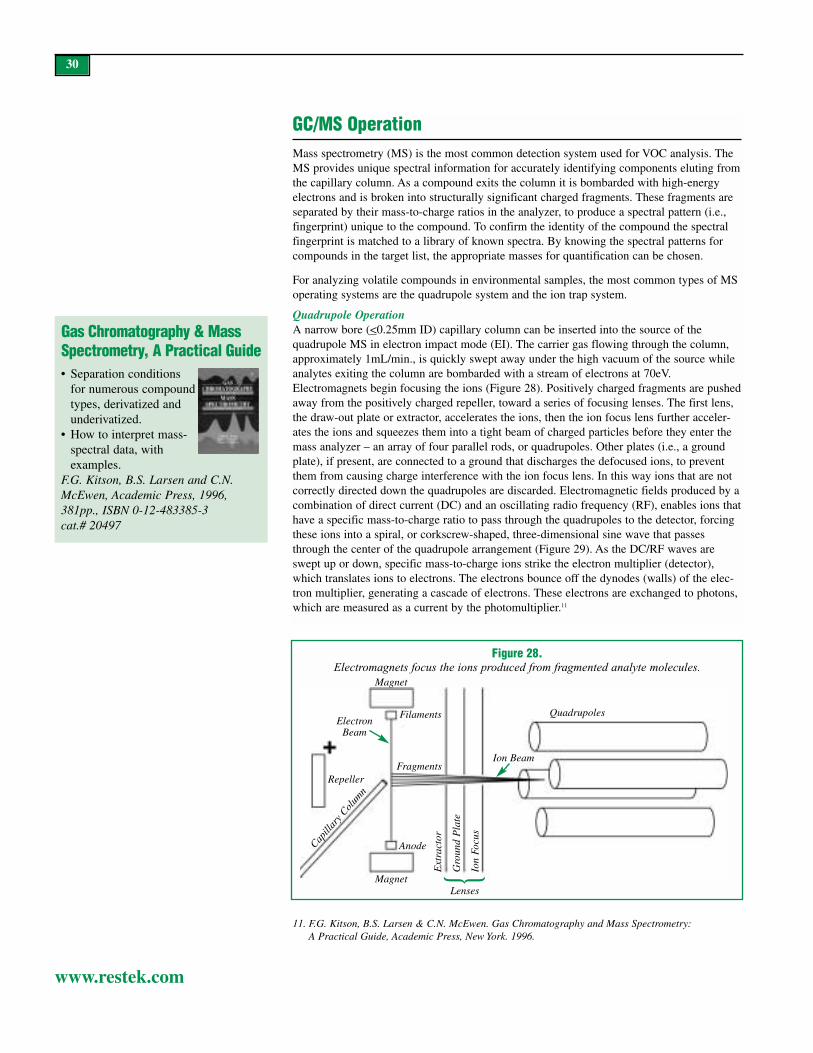
30
www.restek.com
GC/MS OperationMass spectrometry (MS) is the most common detection system used for VOC analysis. TheMS provides unique spectral information for accurately identifying components eluting fromthe capillary column. As a compound exits the column it is bombarded with high-energy electrons and is broken into structurally significant charged fragments. These fragments areseparated by their mass-to-charge ratios in the analyzer, to produce a spectral pattern (i.e.,fingerprint) unique to the compound. To confirm the identity of the compound the spectralfingerprint is matched to a library of known spectra. By knowing the spectral patterns forcompounds in the target list, the appropriate masses for quantification can be chosen.
For analyzing volatile compounds in environmental samples, the most common types of MSoperating systems are the quadrupole system and the ion trap system.
Quadrupole OperationA narrow bore (<0.25mm ID) capillary column can be inserted into the source of thequadrupole MS in electron impact mode (EI). The carrier gas flowing through the column,approximately 1mL/min., is quickly swept away under the high vacuum of the source whileanalytes exiting the column are bombarded with a stream of electrons at 70eV.Electromagnets begin focusing the ions (Figure 28). Positively charged fragments are pushedaway from the positively charged repeller, toward a series of focusing lenses. The first lens,the draw-out plate or extractor, accelerates the ions, then the ion focus lens further acceler-ates the ions and squeezes them into a tight beam of charged particles before they enter themass analyzer – an array of four parallel rods, or quadrupoles. Other plates (i.e., a groundplate), if present, are connected to a ground that discharges the defocused ions, to preventthem from causing charge interference with the ion focus lens. In this way ions that are notcorrectly directed down the quadrupoles are discarded. Electromagnetic fields produced by acombination of direct current (DC) and an oscillating radio frequency (RF), enables ions thathave a specific mass-to-charge ratio to pass through the quadrupoles to the detector, forcingthese ions into a spiral, or corkscrew-shaped, three-dimensional sine wave that passesthrough the center of the quadrupole arrangement (Figure 29). As the DC/RF waves areswept up or down, specific mass-to-charge ions strike the electron multiplier (detector),which translates ions to electrons. The electrons bounce off the dynodes (walls) of the elec-tron multiplier, generating a cascade of electrons. These electrons are exchanged to photons,which are measured as a current by the photomultiplier.11
Figure 28.Electromagnets focus the ions produced from fragmented analyte molecules.
Ion BeamFragments
Ext
ract
or
Gro
und
Pla
te
Ion
Focu
s
Magnet
Magnet
Anode
QuadrupolesFilamentsElectron
Beam
Repeller
Lenses
Capill
ary C
olum
n
11. F.G. Kitson, B.S. Larsen & C.N. McEwen. Gas Chromatography and Mass Spectrometry:A Practical Guide, Academic Press, New York. 1996.
{
Gas Chromatography & MassSpectrometry, A Practical Guide• Separation conditions
for numerous compoundtypes, derivatized andunderivatized.
• How to interpret mass-spectral data, withexamples.
F.G. Kitson, B.S. Larsen and C.N.McEwen, Academic Press, 1996,381pp., ISBN 0-12-483385-3cat.# 20497

31
www.restek.com
Ion Trap OperationThe major difference between a quadrupole MS and an ion trap MS are the mechanisms ofion focus and scanning. Three hyperbolic electrodes, a ring and two endcaps, form the coreof an ion trap MS (Figure 30). In electron impact mode the sample is ionized, fragmented,and introduced into the ion trap through a pulsing electronic gate that opens and closes, con-trolling the number of ions that enter the trap. Ions that enter the trap are stored in stableorbits. Adjusting the voltage around the ring electrode pushes some of these ions into unsta-ble orbits, causing them to exit to the detector. Because all ions entering the trap are storedtemporarily, only a finite amount of sample can be allowed to enter the trap area, otherwisethe system would be overloaded.
Interfacing the Capillary Column to the MSThe ion source and analyzer of the MS are under vacuum. To enable the pumping system tomaintain this vacuum, the volume of carrier gas entering the MS must be small. Regardlessof the pumping capacity of the MS vacuum system, the best sensitivity is achieved if thecarrier gas flow rate is approximately 1mL/min. Because a narrow-bore capillary columnroutinely is operated at near 1mL/min. flow rates, it can be connected directly to the MSwithout overwhelming the pumping system. Wide-bore capillary columns, however, usuallyare operated at flow rates that are too high for most MS systems. Consequently, an interfacemust be used to reduce the flow to a level that is compatible with the MS pumping system.Figure 31 shows the two most common interfaces – the open split and the jet separator.
An open split interface (OSI) functions like an inlet splitter system in a chromatograph. Itallows as much as 90% of the carrier gas to be vented away from the MS vacuum system.Correspondingly, this is reflected by a sample loss of up to 90%, which reduces sensitivityby an order of magnitude. Therefore, an OSI is not suitable for trace-level environmentalanalysis. Splitting the sample at the injection port, combined with analysis on a narrow-borecolumn, is favored over using an OSI because a high desorb flow rate can be used to ensurebetter sample transfer from the trap. Also, a 0.25mm ID or narrower column increases effi-ciency and improves resolution of analytes.
Another alternative to an OSI, the jet separator, reduces the carrier gas flow without signifi-cant loss of sensitivity. A jet separator works on the principle of momentum. Very smallmolecules such as helium (or other carrier gas) do not have sufficient momentum to passacross a small gap in the jet separator and are routed away from the MS, using a vacuumpump. Larger molecules, such as most target components, have the necessary momentum tocarry them across the gap and into the MS. Using this device, much of the carrier gas can beeliminated without significant loss of target compounds. Added momentum is required tocarry very small analyte molecules, such as gases, across the gap, however. In these situa-tions we recommend adding make-up gas to provide the extra momentum and improveresponses for low molecular weight target compounds.
Figure 29.Electromagnetic fields force the ions into a spiral, three-dimensional
sine wave through the center of the quadrupole arrangement.
AMUOffset
Gamma Rays
DynodeSurface
ElectronNullifierSignal
+
+
-
-
Figure 30.Ring and end caps form the
core of an ion trap MS.

32
www.restek.com
MS Calibration and TuningCalibration allows the correct identification of masses, whereas tuning adjusts the intensityand peakwidths for masses. The MS is calibrated by adjusting the DC/RF frequency so thatmass axis points are aligned with expected mass fragments of known spectra. Tuningensures that target compounds analyzed on the MS will have the same distribution (pattern)of ions, and peak widths for ions will be narrow enough that adjacent mass peaks will notoverlap. A compound widely used for calibrating and tuning MS systems is perfluorotributy-lamine (PFTBA or FC43). Modern instruments introduce PFTBA into the ion source duringthe autotune procedure. The instrument software adjusts the MS parameters to match theknown fragmentation pattern for PFTBA. The ion of greatest abundance in the spectrum ismass 69; the relative abundances of masses 131 and 219 are roughly 50% of that for mass69 (Figure 32). In analyses of volatiles, mass 502 is less important because its relative abun-dance is 1% of the mass 69 value. Low peak heights or a loss of mass 502 generally indicatea cleanliness problem at the source.
Specific Tuning Requirements: 4-Bromofluorobenzene: After the system is calibrated andtuned, using PFTBA, a 50ng solution of 4-bromofluorobenzene (BFB) is introduced. BFBusually is introduced by injection through the GC injection port but, alternatively, it can bepurged from a water blank. Abundance criteria for BFB are listed in Table IV.
If tuning with BFB fails under criteria acceptable for PFTBA, decrease the relative abun-dance of masses 131 and 219 to 30% of mass 69 by adjusting the entrance lens. If necessary,slightly decrease the repeller voltage. This procedure targets the ions from mass 173 throughmass 177. A second tuning failure with BFB may dictate recalibration and tuning withPFTBA. Ion ratios for BFB should be checked every 12 hours. As long as results meet thespecifications in Table IV, no further calibration or tuning is required.
Poor tuning can significantly affect the sensitivity of the MS. Figure 33 shows spectra for asample analyzed twice, first after a failing PFTBA tuning with mass 131 as the base peak(Figure 33, A), then after a passing tuning (Figure 33, B). The second analysis exhibits athree-fold increase in sensitivity.
Figure 31.An open split interface or a jet separatorwill reduce the gas flow entering a mass
spectrometer vacuum system.
Figure 32.Perfluorotributylamine (PFTBA) fragmentation, using a quadrupole mass spectrometer.
100
80
60
40
20
050 100 150 200 250 300 350 400 450 500 550 600
69
131
219
502
Table IV.US EPA ion abundance criteria for 4-bromofluorobenzene (BFB).
Mass/Charge Ratio Relative Abundance Criterion50 15-50% of mass 9575 30-80% of mass 9595 Base peak, 100% relative abundance96 5-9% of mass 95173 <2% of mass 174174 >50% of mass 95175 5-9% of mass 174176 >95% but <101% of mass 174177 5-9% of mass 176
purge outpurge in
to MSD
1:10split
toMSD
vacuum
make-upgas
carriergas
jet separator
open split interface

33
www.restek.com
Leak Checks: The MS is a powerful tool for determining the presence of leaks in theGC/MS system because it is able to detect air and water. Check for leaks by turning on thePFTBA valve and scanning for m/z 69, 18, and 28. By using the base peak for PFTBA (m/z69), a relative concentration of water/nitrogen can be determined. The combined relativeabundance of 18/28 to 69 should be between 0.1% and 3%. Figure 34 shows an air/watervalue of 0.14% (0.05+0.09). If the value is below 0.1%, compare the current total abun-dance of ion 69 with its abundance at the last leak check. Instruments with large leaks havereduced sensitivity for 69 and may show abundances of 0 for lower ions, suggesting there isno leak. This is due to saturation of the detector. If a leak is present, the instrument will nottune. An MS with a diffusion pump should be allowed more time to equilibrate because it isless efficient at removing low molecular weight contamination. After this preliminaryair/water check, begin tuning the instrument. After the instrument passes tuning, check againfor air and water.
Figure 33.Optimize MS tuning to increase sensitivity.
A - Before tuneB - After tune
320000
280000
240000
200000
160000
120000
80000
40000
Abu
ndan
ce
1.00Time 1.40 1.80 2.20 2.60 3.00 3.40 3.80 4.20 4.60 5.00 5.40 5.80
Figure 34.An initial air/water check on an Agilent 5971A MS, before tuning.

34
www.restek.com
Identifying Target AnalytesQualitative identification of a target compound is based on retention time (± 0.06 minutes) andon comparison of the sample mass spectrum to a reference mass spectrum. Compounds areidentified from three ions of the greatest intensity. The quantification ion, usually the highestm/z fragment, is used for determining the concentration of a particular analyte. When usingany column for GC/MS, attention must be given to coeluting compounds to determine ifacceptable quantification ions can be found. It is important that there be no coelution betweencompounds sharing ions used for quantification. As long as unique ions can be selected forquantifying compounds that share retention time, chromatographic coelution is acceptable.Reducing analysis time without carefully checking for coelutions can lead to problems. Forexample, internal standard chlorobenzene-d5 and analyte 1,1,1,2-tetrachloroethane, whichshare quantification ion 117, can coelute from a “VMS,” “624,” or “VRX” stationary phase.Many laboratories eliminate the need for chromatographic resolution by changing the quantifi-cation ion for chlorobenzene-d5 from 117 to 82 (Figure 35). An alternative solution is toreplace chlorobenzene-d5 with another internal standard that elutes in the same region of thechromatogram, such as 4-bromofluorobenzene. In performance-based measurement systems(PBMS), surrogates and internal standards may be changed, as long as the analyst can showthat the performance will be equivalent or better. Auditors for state or local regulatory agenciesmight not allow these changes, however. An additional option, the suggested surrogates can beused and the analysis performed using a slower GC oven temperature program that resolvesthe coelution (Figure 36). This option eliminates the need to change either the internal standardor the quantification ion, but prolongs analysis time. An analysis time of less than 10 minutes,with chromatographic resolution of these compounds, is possible with a 20m x 0.18mm x1.0µm df Rtx®-VMS column (see Application section, page 51).
Identifying Non-Target AnalytesFor samples containing analytes that do not match retention time and/or mass spectra for thetarget compounds, a library search can be used in an attempt to match the unknown spectrawith known spectra. Unknown compounds in the sample, referred to as tentatively identifiedcompounds (TICs), should be reported only as estimates.
Mass Spectral Clues for Identifying TICs: The MS provides three valuable clues to identi-fying TICs: parent ion, isotopic composition, and common fragmentation ions. The parention (also known as the molecular weight ion) is the ionized form of the neutral compound,but not all compounds are stable enough to produce a molecular weight ion. Most environ-mental contaminants, except compounds that contain nitrogen, will have an even numbermass for a parent ion. The parent ion reveals information about the elemental compositionand the distribution of isotopes. The term “isotope” is used to describe atoms of an elementwith differing numbers of neutrons. Most elements have isotopes in a particular distributionto each other. For example, carbon occurs primarily in two forms, 12C and 13C. 13C is at anabundance of 1.1% relative to 12C.12 This information can contribute to determining the num-ber of carbons present in the fragmented ion. Carbon is considered an A+1 element becauseits isotopes vary by 1amu. Compounds such as oxygen, sulfur, silicon, chlorine, and bromineare A+2 elements because their isotopes vary by 2amu or more (Figure 37, page 35).Fragmentation ions also can offer clues to compound composition (Table V).
Leak-Free Column/MS Installation Using an Injection Port ConnectionThe most common problem associated with volatiles analyses by GC/MS is the presence ofleaks. The following procedure will help ensure optimum performance. Do not use this pro-cedure with columns with IDs larger than 0.25mm, because the amount of oxygen thatwould be introduced into the MS source during the last step will oxidize the metal parts andreduce sensitivity.
Figure 36.A slower oven temperature program
eliminates the need to change the internalstandard or the quantification ion.
chlorobenzene-d5ethylbenzenechlorobenzene
Figure 35.The quantification ion for
chlorobenzene-d5 can be changed from ion 117 to ion 82, to eliminate the
need for chromatographic resolution from1,1,1,2-tetrachloroethane.
Ion 117
Ion 82
Ion 131
ion
117
ion
117
}chlorobenzene-d5
Extracted ion chromatogram (black)overlayed on total ion chromatogram (green)
1,1,1,2-tetrachloroethene
12. F.W. McLafferty and F. Turecek. Interpretation of Mass Spectra, University Science Books, MillValley, 4th edition, 1993, pp. 283-291.

35
www.restek.com
MSD Source Nut(Similar to Agilent part # 05988-20066.)Description qty. cat.#(Detector) MSD Source Nut 2-pk. 20643
Figure 38.To check for leaks, cap the split vent and
septum purge vent lines on the GC and thecolumn, then shut off the gas supply.
System pressure should remain constant.
Cap both
Connect the capillary column, 0.25mm ID or smaller, to the injection port, but not to theMS source, and condition the column. When the column has been conditioned, remove50cm from the detector end of the column to ensure complete removal of siloxanes andother potential contaminants. Then, with the MS still turned off, insert the column end intothe MS source. Cut the column several centimeters from the connection to the injection port.Use septa to cap the short length of column that is left in the injection port and the new,unconnected inlet end of the column. Also cap the split vent and septum purge vent lines onthe GC (Figure 38). Perform a pressure decay test on the injection port by setting the pres-sure to 30psi, then shutting off the gas supply. The pressure should remain constant for atleast 1 minute. If the pressure drops in less than 1 minute, turn on the gas supply and beginleak checking, using an electronic leak detector, such as the Restek Leak DetectiveTM II (cat.#20413, page 36).
Once you have confirmed the GC system is leak-tight, and while the injection port end ofthe column is capped and there is no flow in the column, evacuate the MS and record thesource pressure in your maintenance logbook. After several hours equilibration, perform theinstrument leak-check using PFTBA (see MS Calibration and Tuning, page 32). If a leak ispresent, draw 500µL of methanol into a syringe and apply drops of this solvent on areaswhere leaks might be suspected, while scanning for mass 31. Alternatively, bathe these areaswith argon gas and scan for m/z 40. The brass source nut is the primary place for leaks in anMS, this nut should be replaced every time the column is changed (cat. #20643, page 35).Other areas to examine include the rubber seals and the PFTBA vial.
After you confirm the MS is leak-free, quickly install the inlet end of the column into theinjection port. The MS will draw air into the source during this connection time; after anoth-er 2-hour equilibration the MS is ready for tuning/leak checking using PFTBA.
Figure 37.Cl and Br are examples of A+2 elements (isotopes vary by 2amu or more).
Element Mass % Abundance Mass % Abundancecarbon 12 100 13 1.1nitrogen 14 100 15 0.37chlorine 35 100 37 32.5bromine 79 100 81 98oxygen 16 100 18 0.2
BrCl Cl2 Br2
Table V.Fragment ions can offer clues to compound composition.
Compound Class Fragment IonsAldehydes, amides, amines 44, 58, 72, 59, 30Aliphatic hydrocarbons 43, 57, 71, 85, 99Alkylbenzenes 104, 91Aromatic hydrocarbons 39, 50, 51, 52, 63, 65, 76, 77, 91Fluorine-containing 50, 69Methacrylates 41, 69Methyl ketones 43, 58Oxygen-containing 31,45,59,73Sulfur-containing 47,61Unsaturated hydrocarbons 41, 55, 69

36
www.restek.com
Table VI.Common contaminants and their identifying ions.
Contaminant Characteristic Fragmentation IonsSilicon 73, 147, 207, 221, 281, 355, 429, 503Rough vacuum pump oil 55-57, 61-67, 81-85, 95-99Diffusion pump oil 77, 115, 141, 168, 223, 260, 446Plasticizers 149, 223, 278
MS ContaminationA universal detector, the MS responds to all organic compounds and, consequently, any con-tamination potentially can interfere with target analyte identification. The common sourcesof contamination are column bleed and septum bleed. High column bleed can be an indica-tion of oxygen entering the system and degrading the stationary phase in the column. If highcolumn bleed is suspected, conduct a leak check of the system, using the proceduredescribed on page 34 and 35. Septum bleed introduces silicon fragments, characterized byion 73, into the system. Silicon compounds also are components of GC and MS seals. TableVI lists common contaminants and the ions by which they can be identified.
Water / Methanol: The introduction of water and/or methanol vapor from the purge and trapsystem can cause problems in an MS system. Excess water vapor entering the MS candecrease the ionization of target analytes eluting at the same time. To overcome problemsassociated with water vapor, use a trap containing hydrophobic adsorbents, such as theVocarb® 3000 trap. If you are using an ion trap system, increase the split ratio in the injec-tion port. This will prevent overloading the ion trap and will increase overall linearity for thegaseous analytes.
Leak Detective™ IILeak Detector
* Never use liquid leak detectors on a capil-lary system. Liquids can be drawn into thesystem.
** Caution: NOT designed for determiningleaks of combustible gases. A combustiblegas detector should be used for determin-ing combustible gas leaks in possibly haz-ardous conditions.
Description qty. cat.#Leak Detective™ II Leak Detector ea. 20413
• Affordable thermal conductivity leakdetector—every analyst should have one*
• Compact, ergonomic design is easy tohold and operate with one hand.
• Helium, hydrogen, and nitrogen can bedetected at 1x10⁻⁴cc/sec. or at an absoluteconcentration as low as 100ppm**
• Fast results—responds in less than 2 sec-onds to trace leaks of gases with thermalconductivities different than air.
• Micro-chip design improves sensitivityand response time over previous models.
• Auto zeroing with the touch of a button.• Battery-operated for increased portability
(one 9-volt).
Practical Introduction to GC/MS Analysis with QuadrupolesThe text gives answers to questions such as: how does the massspectrometer work, what problems can occur and how do I detectthem, how must separation and detection be adapted to each other,and what pitfalls can be avoided when elucidating structures andquantifying compounds.M. Oehme, Wiley-VCH1999, 195pp., ISBN 3-527-29748-0cat.# 21098
Interpretation of Mass Spectra, 4th EditionThis updated version builds on the strengths of the previous editionsand presents the information required to clearly and concisely inter-pret mass spectra. Chapters include information on elemental com-position, molecular ions, mechanisms of ion fragmentations, unimol-ecular ion decompositions, and mass spectra of common compoundclasses. It is valuable and necessary resource for every person prac-ticing mass spectrometry.F.W. McLafferty and F. Turecek, University Science1993, 371pp., ISBN 0-935702-25-3cat.# 20498

37
www.restek.com
Applications Using GC Detection SystemsPurge and Trap Applications Using Tandem PID-ELCD:US EPA Methods 502.2, 601, 602, 8010, 8020, 8021BEPA methods for GC analyses of volatile compounds require purge and trap units for con-centrating the contaminants in water, soil, or wastewater. While purge and trap concentrationsignificantly increases sensitivity, relative to other sample introduction techniques, it doeshave a downside: early-eluting volatile compounds typically exhibit broad peaks, due toinefficient sample transfer from the trap to the GC. This distorted peak shape decreases res-olution between closely eluting compounds, placing demands on the analytical system andrequiring optimized GC operating conditions. Although cryofocusing improves separationsof early eluting compounds, most environmental laboratories do not use this approachbecause it increases costs.
EPA methods for monitoring volatiles by GC often recommend using a PID and an ELCD,connected in tandem or series. Coelutions of target compounds are allowed, as long as theyare resolved by the detectors.13 For example, in Figure 39 bromoform and styrene elute withthe same retention time, but bromoform elicits a response only from the ELCD and styreneelicits a response only from the PID. Thus, the selective detectors resolve these two com-pounds. Because it characteristically produces tailing peaks, the ELCD is the more problem-atic of the two detectors; sensitivity can be increased, but not without a sacrifice in peakshape. Optimization of an ELCD minimizes tailing and maximizes sensitivity.
Analysis Time: Several factors contribute to the total analysis time for volatiles separations,including purge and trap cycle time, sample analysis time, and GC oven cool-down time(time required for the oven to cool from the final temperature to the initial temperature forthe next analysis). Long purge and trap cycles are a product of long purge times, dry purges,long desorb times, and long trap bake times. Long oven cycle times result from low initialoven temperatures (i.e., subambient to 35°C) and slow temperature program rates. A columnthat unnecessarily exceeds the length needed to resolve the analytes can increase analysistime and cost without significantly adding to the data obtained.
An Rtx®-VGC primary column paired with an Rtx®-VRX confirmation column make a goodcombination for analyzing the compounds listed in Figures 39A & B. The target listincludes unregulated but commonly analyzed compounds such as methyl-tert-butyl ether(MTBE) and Freon® 113 (1,1,2-trichloro-1,2,2-trifluoroethane). A 35°C starting temperatureis necessary to resolve Freon®113 from 1,1-dichloroethane. Figure 39A shows there are noearly-analyte coelution problems on the primary column when using PID/ELCD detectors intandem – the gases and the trihalomethanes are separated.
Figures 40A & B show the analysis of Method 8021A/502.2 compounds, without Freon®
113, using an Rtx®-VGC column and an Rtx®-502.2 column. A 50°C initial oven tempera-ture can be used, which greatly reduces the time needed for the GC to complete the ovencycle and return to the starting temperature (cycle time) and, therefore, increases through-put. An Agilent 5890 GC oven will cool from 205°C to 35°C in 9 minutes; this time, addedto the 28-minute analysis time in Figure 39, produces the fastest cycle time for this analysis:37 minutes. In the analysis in Figure 40, the starting temperature is 50°C, the final tempera-ture is 200°C, and the oven takes 4 minutes to cool. The total cycle time, less than 30 min-utes, is significantly faster than for other pairs of columns. For example, an Rtx®-VRX col-umn requires a starting temperature of 40°C; this, combined with a 28 minute analysis time,means the total cycle time cannot be faster than 35 minutes.
13. EPA Method 8000B, Determinative Chromatographic Separations; US EPA. U.S. GovernmentPrinting Office: Washington, DC, 1996, Rev. 2.

38
www.restek.com
Figure 39A.An Rtx®-VGC primary column and an Rtx®-VRX confirmation column separate volatile organic gases from the trihalomethanes –
there are no coelutions on the primary column using the PID/ELCD detectors in tandem.
1. dichlorodifluoromethane2. chloromethane3. vinyl chloride4. bromomethane5. chloroethane6. trichlorofluoromethane7. 1,1-dichloroethene8. Freonfi 1139. allyl chloride
10. methylene chloride11. trans-1,2-dichloroethene12. methyl tert-butyl ether13. 1,1-dichloroethane14. cis-1,2-dichloroethene15. 2,2-dichloropropane16. bromochloromethane17. chloroform
18. carbon tetrachloride19. 1,1,1-trichloroethane20. 1,1-dichloropropene21. benzene22. 1,2-dichloroethane23. fluorobenzene (SS)24. trichloroethene25. dibromomethane26. 1,2-dichloropropane27. bromodichloromethane28. 1-bromo-2-chloroethane (SS)29. cis-1,3-dichloropropene30. toluene31. tetrachloroethene32. trans-1,3-dichloropropene33. 1,1,2-trichloroethane34. dibromochloromethane
35. 1,3-dichloropropane36. 1,2-dibromoethane37. 1-chloro-3-fluorobenzene (SS)38. chlorobenzene39. ethylbenzene40. 1,1,1,2-tetrachloroethane41. m-xylene42. p-xylene43. o-xylene44. styrene45. bromoform46. isopropylbenzene47. bromobenzene48. n-propylbenzene49. 1,1,2,2-tetrachloroethane50. 2-chlorotoluene51. 1,2,3-trichloropropane
52. 1,3,5-trimethylbenzene53. 4-chlorotoluene54. tert-butylbenzene55. 1,2,4-trimethylbenzene56. sec-butylbenzene57. p-isopropyltoluene58. 1,3-dichlorobenzene59. 1,4-dichlorobenzene60. n-butylbenzene61. 1,2-dichlorobenzene62. 1,2-dibromo-3-chloropropane63. hexachlorobutadiene64. 1,2,4-trichlorobenzene65. naphthalene66. 1,2,3-trichlorobenzene
20ppb in 5mL of RO water.Primary column: 75m, 0.45mm ID, 2.55 m Rtxfi -VGC (cat.# 19409)Confirmation column: 75m, 0.45mm ID, 2.55 m Rtxfi -VRX (cat.# 19309)Concentrator: Tekmar LSC-3000 Purge and TrapTrap: Vocarb 3000 Purge: 11 min. @ 40mL/min. Dry purge: 1 min. @ 40mL/min. (MCS by-passed with
Silcosteelfi tubing [cat.# 21035])Desorb preheat: 245 CDesorb: 250 C for 2 min. Bake: 260 C for 8 min.Interface: directTransfer line: 0.32mm ID Siltek tubing (Cat. #10027)
GC: Finnigan 9001Oven temp.: 35 C (hold 4 min.) to 75 C @ 3 C/min. (hold 2 min.)
to 175 C @ 21 C/min. to 205 C @ 35 C/min. (hold 5 min.) Carrier gas: helium 11mL/min., constant pressure
Adjust dichlorodifluoromethane to a retention time of 2.28 min.@ 35 C on the Rtxfi -VGC column.
Detectors: Gold Tandem PID/HALL 2000 ELCDPID: makeup 7mL/min., purge 7mL/min., set @ 0.35mV, base temp 200 C.Hall 2000 ELCD: RxnGas 25mL/min., RxnTemp. 940 C, propanol flow 470 L/min.
Rtx®-VGC 75m, 0.45mm ID, 2.55µm (cat.# 19409)
PID
min. 5 10 15 20 25
37
11
12
14
20
21
2324
29
30
3132
37
63
64
65
66
37
3839
41,42
43
44
46
47
48
50
5253
54
55
5657
5958
6061
22 23 24 25 26
Innovations at WorkRtx®-VGC polymer speciallydesigned for volatiles analysis byPID/ELCD. Freon® 113 added.
ELCD
47
49
50
51
53
24 24.5 25
7
8
9
10
11
13
4
5
6
12
3
20
22
23
24
25
2627
28
29
3132
3314
15
16
17
18
19
34
35
36
37
38
40
45
58
59
62
61
63
64
66
Acknowledgement: Finnigan 9001 GC, µGold Tandem Photoionization/HALL® 2000 Electrolytic Conductivity Detector provided courtesy of Thermo Finnigan GC& GC/MS Division, 2215 Grand Avenue Pkwy, Austin, Texas 78728
GC_EV00416min. 5 10 15 20 25

39
www.restek.com
Figure 39B.An Rtx®-VGC primary column and an Rtx®-VRX confirmation column separate volatile organic gases from the trihalomethanes –
there are no coelutions on the primary column using the PID/ELCD detectors in tandem.
min. 5 10 15 20 25 30min. 5 10 15 20 25
PID
PID ELCD
Rtx®-VRX 75m, 0.45mm ID, 2.55µm (cat.# 19309)
3
7
9
11
12 1420
21
23 24
2932
3031
37
38
39
41 42
44
43
64
65
66
63
1
2
3
4
5
6
7
10
8,9
11
13
14
16
17
15
22
19
20
18
25
26
24,27
28
2932
33
35
34
36
31
37
40
3845
49
51
47
5053
58
59
61
62
64
63
66
31
37
3839
41 42
44
4346
47
48
50
53
52
54
55
56,58
59
5761
60
20.0 22.5 25.0
Acknowledgement: Finnigan 9001 GC, µGold Tandem Photoionization/HALL® 2000 Electrolytic Conductivity Detector provided courtesy of Thermo Finnigan GC& GC/MS Division, 2215 Grand Avenue Pkwy, Austin, Texas 78728
Innovations at WorkRtx®-VRX column is an excellent confirmation column to the Rtx®-VGC column.
23
GC_EV00417
1. dichlorodifluoromethane2. chloromethane3. vinyl chloride4. bromomethane5. chloroethane6. trichlorofluoromethane7. 1,1-dichloroethene8. Freon® 1139. allyl chloride
10. methylene chloride11. trans-1,2-dichloroethene12. methyl tert-butyl ether13. 1,1-dichloroethane14. cis-1,2-dichloroethene15. 2,2-dichloropropane16. bromochloromethane17. chloroform
18. carbon tetrachloride19. 1,1,1-trichloroethane20. 1,1-dichloropropene21. benzene22. 1,2-dichloroethane23. fluorobenzene (SS)24. trichloroethene25. dibromomethane26. 1,2-dichloropropane27. bromodichloromethane28. 1-bromo-2-chloroethane (SS)29. cis-1,3-dichloropropene30. toluene31. tetrachloroethene32. trans-1,3-dichloropropene33. 1,1,2-trichloroethane34. dibromochloromethane
35. 1,3-dichloropropane36. 1,2-dibromoethane37. 1-chloro-3-fluorobenzene (SS)38. chlorobenzene39. ethylbenzene40. 1,1,1,2-tetrachloroethane41. m-xylene42. p-xylene43. o-xylene44. styrene45. bromoform46. isopropylbenzene47. bromobenzene48. n-propylbenzene49. 1,1,2,2-tetrachloroethane50. 2-chlorotoluene51. 1,2,3-trichloropropane
52. 1,3,5-trimethylbenzene53. 4-chlorotoluene54. tert-butylbenzene55. 1,2,4-trimethylbenzene56. sec-butylbenzene57. p-isopropyltoluene58. 1,3-dichlorobenzene59. 1,4-dichlorobenzene60. n-butylbenzene61. 1,2-dichlorobenzene62. 1,2-dibromo-3-chloropropane63. hexachlorobutadiene64. 1,2,4-trichlorobenzene65. naphthalene66. 1,2,3-trichlorobenzene
20ppb in 5mL of RO water.Primary column: 75m, 0.45mm ID, 2.55µm Rtx®-VGC (cat.# 19409)Confirmation column: 75m, 0.45mm ID, 2.55µm Rtx®-VRX (cat.# 19309)Concentrator: Tekmar LSC-3000 Purge and TrapTrap: Vocarb™ 3000 Purge: 11 min. @ 40mL/min. Dry purge: 1 min. @ 40mL/min. (MCS by-passed with
Silcosteel® tubing [cat.# 21035])Desorb preheat: 245°CDesorb: 250°C for 2 min. Bake: 260°C for 8 min.Interface: directTransfer line: 0.32mm ID Siltek™ tubing (Cat. #10027)
GC: Finnigan 9001Oven temp.: 35°C (hold 4 min.) to 75°C @ 3°C/min. (hold 2 min.)
to 175°C @ 21°C/min. to 205°C @ 35°C/min. (hold 5 min.) Carrier: helium 11mL/min., constant pressure
Adjust dichlorodifluoromethane to a retention time of 2.28 min.@ 35°C on the Rtx®-VGC column.
Detectors: µGold Tandem PID/HALL 2000 ELCDPID: makeup 7mL/min., purge 7mL/min., set @ 0.35mV,base temp 200°C.Hall 2000 ELCD: RxnGas 25mL/min., RxnTemp. 940°C,propanol flow 470µL/min.

Figure 40A.An Rtx®-VGC / Rtx®-502.2 column pair and a 50°C initial temperature reduce
total cycle time to less than 30 minutes for EPA Method 8021A/502.2.
40
www.restek.com
min. 5 10 15 20 25
PID
ELCD
PID ELCD3
7
10
1113
19
20
2223
28
29
3031
62
63
64
65
66
1
2
3
5 6
4
7
8
9
10
12
13
14
15
16
17
18
19
21
23
22
24
25 2627
28
30
31
32
33
34
3536
38
41
44
58
60
61
62
63
64
6657
min.17.5 20.0
19.9 20.0 20.1 20.2 20.3 20.4 20.5
3637
39,40
41
42
43
45
46
47
49
5152
53
54
5556
57
58
5960
46
48
49
50
52
Innovations at WorkFastest cycle time for 8021/502.2!50°C starting temperature bringstotal cycle time to less than 30 min.
GC_EV00418
min. 5 10 15 20 25
1. dichlorodifluoromethane2. chloromethane3. vinyl chloride4. bromomethane5. chloroethane6. trichlorofluoromethane7. 1,1-dichloroethene8. allyl chloride9. methylene chloride
10. trans-1,2-dichloroethene11. methyl tert-butyl ether12. 1,1-dichloroethane13. cis-1,2-dichloroethene14. 2,2-dichloropropane
15. bromochloromethane16. chloroform17. carbon tetrachloride18. 1,1,1-trichloroethane19. 1,1-dichloropropene20. benzene21. 1,2-dichloroethane22. fluorobenzene (SS)23. trichloroethene24. dibromomethane25. 1,2-dichloropropane26. bromodichloromethane27. 1-bromo-2-chloroethane (SS)28. cis-1,3-dichloropropene
29. toluene30. tetrachloroethene31. trans-1,3-dichloropropene32. 1,1,2-trichloroethane33. dibromochloromethane34. 1,3-dichloropropane35. 1,2-dibromoethane36. chlorobenzene37. ethylbenzene38. 1,1,1,2-tetrachloroethane39. m-xylene40. p-xylene41. 1-chloro-2-fluorobenzene (SS)42. o-xylene
43. styrene44. bromoform45. isopropylbenzene46. bromobenzene47. n-propylbenzene48. 1,1,2,2-tetrachloroethane49. 2-chlorotoluene50. 1,2,3-trichloropropane51. 1,3,5-trimethylbenzene52. 4-chlorotoluene53. tert-butylbenzene54. 1,2,4-trimethylbenzene55. sec-butylbenzene56. p-isopropyltoluene
57. 1,3-dichlorobenzene58. 1,4-dichlorobenzene59. n-butylbenzene60. 1,2-dichlorobenzene61. 1,2-dibromo-3-chloropropane62. 2-bromo-1-chlorobenzene (SS)63. hexachlorobutadiene64. 1,2,4-trichlorobenzene65. naphthalene66. 1,2,3-trichlorobenzene
Acknowledgement: Finnigan 9001 GC, µGold Tandem Photoionization/HALL® 2000 Electrolytic Conductivity Detector provided courtesy of Thermo Finnigan GC & GC/MSDivision, 2215 Grand Avenue Pkwy, Austin, Texas 78728
Rtx®-VGC 75m, 0.45mm ID, 2.55µm (cat.# 19409)Primary column: 75m, 0.45mm ID, 2.55 m Rtxfi -VGC (cat.# 19409)Confirmation column: 75m, 0.45mm ID, 2.55 m Rtxfi -502.2 (cat.# 10986)Conc.: 10ppb in 5mL of RO waterConcentrator: Tekmar LSC3100 Purge and TrapTrap: Vocarb 3000Purge: 11 min. @ 40mL/min.Dry purge: 1 min. @ 40mL/min.Desorb preheat: 245 CDesorb: 250 C for 2 min.Bake: 260 C for 8 min.Interface: direct connection from concentrator to columnTransfer line: Siltek 0.32mm fused silica transfer line direct to
columns w/ Press-Tight Y connector (cat. # 20403)Gas chromatograph: Finnigan 9001Carrier gas: helium @ ~10mL/min. constant pressure
Adjust dichlorodifluoromethane to a retention time of 2.28 min. @ 50 C on the Rtxfi -VGC column.
Oven temp.: 50 C (hold 2 min.) to 70 C @ 2 C/min. to 130 C @9 C/min. to 200 C @ 40 C/min. (final hold 5 min.)Detectors: Gold Tandem PID/Hall 2000 ELCD
PID: makeup 7mL/min., purge 7mL/min.,set @ 0.35mV base temp 200 C.Hall 2000 ELCD: RxnGas 25mL/min., Temp.940 C,propanol flow 470 L/min.

41
www.restek.com
Figure 40B.An Rtx®-VGC / Rtx®-502.2 column pair and a 50°C initial temperature reduce
total cycle time to less than 30 minutes for EPA Method 8021A/502.2.
1. dichlorodifluoromethane2. chloromethane3. vinyl chloride4. bromomethane5. chloroethane6. trichlorofluoromethane7. 1,1-dichloroethene8. allyl chloride9. methylene chloride
10. trans-1,2-dichloroethene11. methyl tert-butyl ether12. 1,1-dichloroethane13. cis-1,2-dichloroethene14. 2,2-dichloropropane15. bromochloromethane16. chloroform17. carbon tetrachloride18. 1,1,1-trichloroethane19. 1,1-dichloropropene20. benzene21. 1,2-dichloroethane22. fluorobenzene (SS)23. trichloroethene24. dibromomethane25. 1,2-dichloropropane26. bromodichloromethane27. 1-bromo-2-chloroethane (SS)28. cis-1,3-dichloropropene29. toluene30. tetrachloroethene31. trans-1,3-dichloropropene32. 1,1,2-trichloroethane33. dibromochloromethane
34. 1,3-dichloropropane35. 1,2-dibromoethane36. chlorobenzene37. ethylbenzene38. 1,1,1,2-tetrachloroethane39. m-xylene40. p-xylene41. 1-chloro-2-fluorobenzene (SS)42. o-xylene43. styrene44. bromoform45. isopropylbenzene46. bromobenzene47. n-propylbenzene48. 1,1,2,2-tetrachloroethane49. 2-chlorotoluene50. 1,2,3-trichloropropane51. 1,3,5-trimethylbenzene52. 4-chlorotoluene53. tert-butylbenzene54. 1,2,4-trimethylbenzene55. sec-butylbenzene56. p-isopropyltoluene57. 1,3-dichlorobenzene58. 1,4-dichlorobenzene59. n-butylbenzene60. 1,2-dichlorobenzene61. 1,2-dibromo-3-chloropropane62. 2-bromo-1-chlorobenzene (SS)63. hexachlorobutadiene64. 1,2,4-trichlorobenzene65. naphthalene66. 1,2,3-trichlorobenzene
Primary column: 75m, 0.45mm ID, 2.55µm Rtx®-VGC (cat.# 19409)Confirmation column: 75m, 0.45mm ID, 2.55µm Rtx®-502.2 (cat.# 10986)Conc.: 10ppb in 5mL of RO waterConcentrator: Tekmar LSC3100 Purge and TrapTrap: Vocarb 3000Purge: 11 min. @ 40mL/min.Dry purge: 1 min. @ 40mL/min.Desorb preheat: 245°CDesorb: 250°C for 2 min.Bake: 260°C for 8 min.Interface: direct connection from concentrator to columnTransfer line: Siltek 0.32mm fused silica transfer line direct to
columns w/ Press-Tight “Y” connector (cat. #20403)
Gas chromatograph: Finnigan 9001Carrier gas: helium @ ~10 mL/min. constant pressure
Adjust dichlorodifluoromethane to a retention time of 2.28 min. @ 50°C on the Rtx®-VGC column.
Oven temp.: 50°C (hold 2 min.) to 70°C @ 2°C/min. to 130°C @ 9°C/min. to 200°C @ 40°C/min. (final hold 5 min.)
Detectors: µGold Tandem PID/Hall 2000 ELCDPID: makeup 7mL/min., purge 7mL/min., set @ 0.35mVbase temp 200°C.Hall 2000 ELCD: RxnGas 25mL/min., RxnTemp. 940°C,propanol flow 470µL/min.
Rtx®-502.275m, 0.45mm ID, 2.55µm (cat.# 10986)
min. 5 10 15 20 25
3711
10
1319
20
22 23
28
29
31
30
3637
41
45
39,40
42,43
46,47
49 51
52
53,54
5857
56
555960
62
64
65
66
63
1
2
3
4
56
7
8
9
10
12
14,13
16
1518
19
1721
22
23
2526
24
27
2831
32
34
30
33
3536
38
41
44
48
50
52
49
46
57
58
60
61
62
64
63
66
Acknowledgement: Finnigan 9001 GC, µGold Tandem Photoionization/HALL® 2000 Electrolytic Conductivity Detector provided courtesy of Thermo FinniganGC & GC/MS Division, 2215 Grand Avenue Pkwy, Austin, Texas 78728
GC_EV00419min. 5 10 15 20 25
PID ELCD

42
www.restek.com
Figure 41A.Analytes listed in EPA Method 601/602 can be separated in 20 minutes by an Rtx®-VGC / Rtx®-502.2 column pair.
PID ELCD
min. 5 10 15 20
1. dichlorodifluoromethane2. chloromethane3. vinyl chloride4. bromomethane5. chloroethane6. trichlorofluoromethane7. 1,1-dichloroethene8. methylene chloride9. trans-1,2-dichloroethene
10. methyl tert-butyl ether11. 1,1-dichloroethane12. bromochloromethane (SS)13. chloroform14. carbon tetrachloride15. 1,1,1-trichloroethane16. benzene17. 1,2-dichloroethane18. fluorobenzene (SS)19. trichloroethene
20. 1,2-dichloropropane21. bromodichloromethane22. 2-chloroethyl vinyl ether23. cis-1,3-dichloropropene24. toluene25. tetrachloroethene26. trans-1,3-dichloropropene27. 1,1,2-trichloroethane28. dibromochloromethane29. chlorobenzene30. ethylbenzene31. 1-chloro-2-fluorobenzene (SS)32. bromoform33. 1,4-dichlorobutane (SS)34. 1,1,2,2-tetrachloroethane35. 1,3-dichlorobenzene36. 1,4-dichlorobenzene37. 1,2-dichlorobenzene38. 4-bromo-1-chlorobenzene (SS)
Primary column: 75m, 0.45mm ID, 2.55µm Rtx®-VGC (cat.# 19409)Confirmation column: 75m, 0.45mm ID, 2.55µm Rtx®-502.2 (cat.# 10986)Conc.: 10ppb in 5mL of RO waterConcentrator: Tekmar LSC3100 Purge and TrapTrap: Vocarb 3000Purge: 11 min. @ 40mL/min.Dry purge: 1 min. @ 40mL/min.Desorb preheat: 245°CDesorb: 250°C for 2 min.Bake: 260°C for 8 min.Interface: direct connection from concentrator to columnTransfer line: 0.53mm ID Silcosteel® tubing (cat. #70045)Gas chromatograph: Finnigan 9001Carrier gas: helium @ ~10mL/min. constant pressure
Adjust dichlorodifluoromethane to a retention time of 2.47 min. @ 40°C.
Oven temp.: 40°C (hold 2 min.) to 58°C @ 4°C/min. to 90°C @ 10°C/min. (hold 5 min.) to 220°C @40°C/min. (hold 5 min.)
Detectors: µGold Tandem PID/Hall 2000 ELCDPID: makeup 7mL/min., purge 7mL/min., set @0.35mV base temp: 200 C.Hall 2000 ELCD: RxnGas 25mL/min., Rxn Temp. 940 C,propanol flow 470 L/min.
37
9
10
16
1819
2223
24
25
26
29
30
31
3536
37
38
1
2
3
4
5
6
7
89
11
12
13
14
15
17
18
2021
22
23
25
26
27
28
2931
32
33
34
35
36
37
38
19
Acknowledgement: Finnigan 9001 GC, µGold TandemPhotoionization/HALL® 2000 Electrolytic Conductivity Detector providedcourtesy of Thermo Finnigan GC & GC/MS Division, 2215 GrandAvenue Pkwy, Austin, Texas 78728
suggested surrogates: peaks 12, 18, 31, & 38
GC_EV00420
min. 5 10 15 20
Client compound lists might match the compound list in Method 601/602, but the calibration criteria and low detection limits of Method8021 are enforced. Figures 41A & B illustrate common compounds analyzed by GC/PID-ELCD, along with 2-chloroethyl vinyl ether. Thestarting temperature is 40°C, and the analysis time is 20 minutes. An Rtx®-502.2 column is a good choice for this analysis because it exhibitsgood resolution for 2-chloroethyl vinyl ether.
Innovations at Work• Partial, quantifiable separation of
2-chloroethyl vinyl ether (peak 22).
• Fastest analysis (20 min.) for EPAMethod 601/602.
Standard cat.#502.2 mix#1 30042624 cal mix #2 30021624 cal mix #3 30022MTBE 304021,4-dichlorobutane 30227
Standard cat.#fluorobenzene 300301-chloro-2-fluorobenzene 300404-bromo-1-chlorobenzene 30230bromochloromethane 30225
Rtx®-VGC 75m, 0.45mm ID, 2.55µm (cat.# 19409)
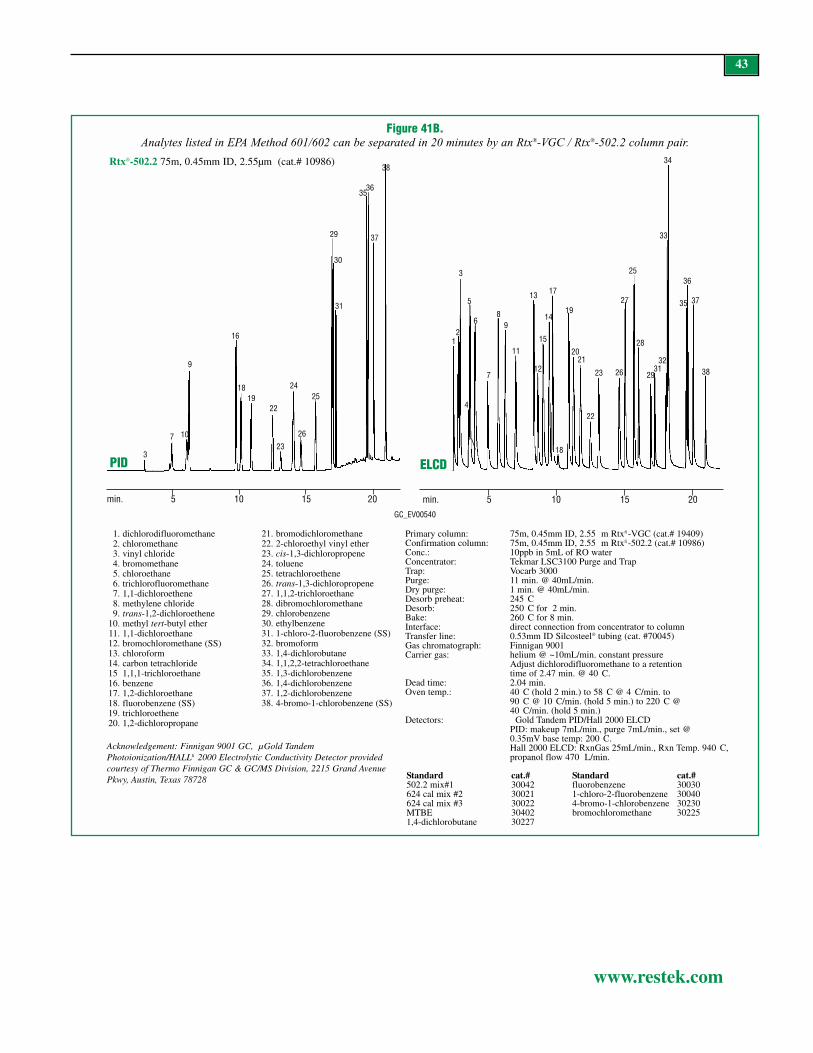
43
www.restek.com
Figure 41B.Analytes listed in EPA Method 601/602 can be separated in 20 minutes by an Rtx®-VGC / Rtx®-502.2 column pair.
min. 5 10 15 20
3
7 10
9
16
1819
22
23
24
26
25
29
30
31
3536
37
38
12
3
4
5
6
7
89
11
13
12
15
14
17
18
19
2021
22
23 26
27
25
28
2931
32
33
34
35
36
37
38
PID ELCD
Primary column: 75m, 0.45mm ID, 2.55 m Rtxfi -VGC (cat.# 19409)Confirmation column: 75m, 0.45mm ID, 2.55 m Rtxfi -502.2 (cat.# 10986)Conc.: 10ppb in 5mL of RO waterConcentrator: Tekmar LSC3100 Purge and TrapTrap: Vocarb 3000Purge: 11 min. @ 40mL/min.Dry purge: 1 min. @ 40mL/min.Desorb preheat: 245 CDesorb: 250 C for 2 min.Bake: 260 C for 8 min.Interface: direct connection from concentrator to columnTransfer line: 0.53mm ID Silcosteel® tubing (cat. #70045)Gas chromatograph: Finnigan 9001Carrier gas: helium @ ~10mL/min. constant pressure
Adjust dichlorodifluoromethane to a retention time of 2.47 min. @ 40 C.
Dead time: 2.04 min.Oven temp.: 40 C (hold 2 min.) to 58 C @ 4 C/min. to
90 C @ 10 C/min. (hold 5 min.) to 220 C @40 C/min. (hold 5 min.)
Detectors: Gold Tandem PID/Hall 2000 ELCDPID: makeup 7mL/min., purge 7mL/min., set @0.35mV base temp: 200 C.Hall 2000 ELCD: RxnGas 25mL/min., Rxn Temp. 940 C,propanol flow 470 L/min.
1. dichlorodifluoromethane2. chloromethane3. vinyl chloride4. bromomethane5. chloroethane6. trichlorofluoromethane7. 1,1-dichloroethene8. methylene chloride9. trans-1,2-dichloroethene
10. methyl tert-butyl ether11. 1,1-dichloroethane12. bromochloromethane (SS)13. chloroform14. carbon tetrachloride15 1,1,1-trichloroethane16. benzene17. 1,2-dichloroethane18. fluorobenzene (SS)19. trichloroethene20. 1,2-dichloropropane
21. bromodichloromethane22. 2-chloroethyl vinyl ether23. cis-1,3-dichloropropene24. toluene25. tetrachloroethene26. trans-1,3-dichloropropene27. 1,1,2-trichloroethane28. dibromochloromethane29. chlorobenzene30. ethylbenzene31. 1-chloro-2-fluorobenzene (SS)32. bromoform33. 1,4-dichlorobutane34. 1,1,2,2-tetrachloroethane35. 1,3-dichlorobenzene36. 1,4-dichlorobenzene37. 1,2-dichlorobenzene38. 4-bromo-1-chlorobenzene (SS)
min. 5 10 15 20
GC_EV00540
Acknowledgement: Finnigan 9001 GC, µGold TandemPhotoionization/HALLfi 2000 Electrolytic Conductivity Detector providedcourtesy of Thermo Finnigan GC & GC/MS Division, 2215 Grand AvenuePkwy, Austin, Texas 78728 Standard cat.#
502.2 mix#1 30042624 cal mix #2 30021624 cal mix #3 30022MTBE 304021,4-dichlorobutane 30227
Standard cat.#fluorobenzene 300301-chloro-2-fluorobenzene 300404-bromo-1-chlorobenzene 30230bromochloromethane 30225
Rtx®-502.2 75m, 0.45mm ID, 2.55µm (cat.# 10986)

44
www.restek.com
Figure 42A.An Rtx®-VGC / Rtx®-502.2 column pair separates the expanded list of compounds in EPA Method 8021B in less than 30 minutes.
Primary column: 75m, 0.45mm ID, 2.55 m Rtxfi -VGC (cat.# 19409)Confirmation column: 75m, 0.45mm ID, 2.55 m Rtxfi -502.2 (cat.# 10986) Conc.: 10ppb in 5mL of RO WaterConcentrator: Tekmar LSC-3000 Purge and TrapTrap: Vocarb 3000Purge: 11 min. @ 40 mL/min. Dry purge: 1 min. @ 40mL/min. (MCS bypassed using Silcosteelfi tubing)Desorb preheat: 245 C, Flow 10mL/min. Desorb: 250 C for 2 min.Bake: 260 C for 8 min.Interface: direct using 0.32mm ID Siltek transfer line (cat. #10027)GC: Finnigan 9001Carrier gas: helium @ ~10mL/min. constant pressure
Adjust dichlorodifluoromethane to a retention time of 2.40 min. @ 45 C on the Rtxfi -VGC column.
Oven temp.: 45 C (hold 4 min.) to 70 C @ 2 C/min. to 210 C @ 20 C/min. (hold 10 min.)
Detectors: Gold Tandem PID/HALL 2000 ELCDPID: makeup 7mL/min., purge 7mL/min., set @ 0.35mV base temp. 200 C.Hall 2000 ELCD: RxnGas 25mL/min., RxnTemp.940 C, propanol flow 470 L/min.
PID
ELCD
PID ELCD
Rtx®-VGC75m, 0.45mm ID, 2.55µm (cat.# 19409)
3
9 13
710
14
15
16
1824
25
2728
33,34
35
3637
70
72
71
73
74
7576
1
2
3
4
5
6
7,8
9
11
12
13
16 17
18
20
19
21
22
23
24
26
27
28
29
30 31
32
33,34
3637
38
39
40
4142
44
47
50
60
64
6568
69
70
74
71
72
4243
45 46
47
48
49
51
52
5355
57
58
59
61
6263
6465
66,67
68
52
54
55
56
58
min. 5 10 15 20 25
20.0 20.5 21.0 21.5 22.0 22.5 23.0 23.5 24.0
22.2 22.3 22.4 22.5 22.6 22.7 22.8
66
GC_EV00421
min. 5 10 15 20 251. dichlorodifluoromethane2. chloromethane3. vinyl chloride4. bromomethane5. chloroethane6. trichlorofluoromethane7. 1,1-dichloroethene8. Freonfi 1139. chloromethyl methyl ether
10. iodomethane (40ppb)11. allyl chloride12. methylene chloride13. trans-1,2-dichloroethene14. methyl tert-butyl ether15. tert-butyl alcohol (40ppb)16. chloroprene
17. 1,1-dichloroethane18. cis-1,2-dichloroethene19. 2,2-dichloropropane20. bromochloromethane21. chloroform22. carbon tetrachloride23. 1,1,1-trichloroethane24. 1,1-dichloropropene25. benzene26. 1,2-dichloroethane27. fluorobenzene (SS)28. tetrachloroethene29. dibromomethane30. 1,2-dichloropropane31. bromodichloromethane32. 1-bromo-2-chloroethane (SS)
33. 2-chloroethyl vinyl ether34. cis-1,3-dichloropropene35. toluene36. tetrachloroethene37. trans-1,3-dichloropropene38. 1,1,2-trichloroethane39. dibromochloromethane40. 1,3-dichloropropane41. 1,2-dibromoethane42. chlorobenzene43. ethylbenzene44. 1,1,1,2-tetrachloroethane45. m-xylene46. p-xylene47. 1-chloro-2-fluorobenzene (SS)48. o-xylene
49. styrene50. bromoform51. isopropylbenzene52. bromobenzene53. n-propylbenzene54. 1,1,2,2-tetrachloroethane55. 2-chlorotoluene56. 1,2,3-trichloropropane57. 1,3,5-trimethylbenzene58. 4-chlorotoluene59. tert-butylbenzene60. pentachloroethane61. 1,2,4-trimethylbenzene62. sec-butylbenzene63. p-isopropyltoluene64. 1,3-dichlorobenzene
65. 1,4-dichlorobenzene66. benzyl chloride67. n-butylbenzene68. 1,2-dichlorobenzene69. 1,2-dibromo-3-chloropropane70. 2-bromo-1-chlorobenzene (SS)71. hexachlorobutadiene72. 1,2,4-trichlorobenzene73. naphthalene74. 1,2,3-trichlorobenzene75. 2-methylnaphthalene (40ppb)76. 1-methylnaphthalene (40ppb)
Acknowledgement: Finnigan 9001 GC, µGold TandemPhotoionization/HALL® 2000 Electrolytic ConductivityDetector provided courtesy of Thermo Finnigan GC &GC/MS Division, 2215 Grand Avenue Pkwy, Austin,Texas 78728
The chromatograms in Figures 42A & B incorporate a broader range of analytes, many of which are listed in EPA Method 8021B, along withother requested compounds, such as 1-methylnaphthalene and 2-methylnaphthalene. Of these 72 target compounds, those that coelute on theRtx®-VGC column are resolved by the Rtx®-502.2 column. Even with the addition of the semivolatile methylnaphthalenes, the analysis timeis less than 30 minutes.

45
www.restek.com
Figure 42B.An Rtx®-VGC / Rtx®-502.2 column pair separates the expanded list of compounds in EPA Method 8021B in less than 30 minutes.
PID ELCD3
7,9
15
10,11
14
13
16
1824
25
27 28
3334
35
37
36
70
72
73
71
74
75 76
1
2
3
4
5
6
8
7,9
10,11
12
13
1716
19,1821
2023
24
22
26
27
28
30 31
29
33
32
34
37
38
36,40
39
44
41
42
47
50
54
56
55
58
52
60
6465
68
66
69
70
72
71
74
min. 5 10 15 20 25 30
PID
4243
47
45
48,49
46
51
53
52
55,57
5859,61
6263
64 65
66
6768
min. 22.5 25.0
1. dichlorodifluoromethane2. chloromethane3. vinyl chloride4. bromomethane5. chloroethane6. trichlorofluoromethane7. 1,1-dichloroethene8. Freonfi 1139. chloromethyl methyl ether
10. iodomethane (40ppb)11. allyl chloride12. methylene chloride13. trans-1,2-dichloroethene14. methyl tert-butyl ether15. tert-butyl alcohol (40ppb)16. chloroprene
17. 1,1-dichloroethane18. cis-1,2-dichloroethene19. 2,2-dichloropropane20. bromochloromethane21. chloroform22. carbon tetrachloride23. 1,1,1-trichloroethane24. 1,1-dichloropropene25. benzene26. 1,2-dichloroethane27. fluorobenzene (SS)28. trichloroethene29. dibromomethane30. 1,2-dichloropropane31. bromodichloromethane32. 1-bromo-2-chloroethane (SS)
33. 2-chloroethyl vinyl ether34. cis-1,3-dichloropropene35. toluene36. tetrachloroethene37. trans-1,3-dichloropropene38. 1,1,2-trichloroethane39. dibromochloromethane40. 1,3-dichloropropane41. 1,2-dibromoethane42. chlorobenzene43. ethylbenzene44. 1,1,1,2-tetrachloroethane45. m-xylene46. p-xylene47. 1-chloro-2-fluorobenzene (SS)48. o-xylene
49. styrene50. bromoform51. isopropylbenzene52. bromobenzene53. n-propylbenzene54. 1,1,2,2-tetrachloroethane55. 2-chlorotoluene56. 1,2,3-trichloropropane57. 1,3,5-trimethylbenzene58. 4-chlorotoluene59. tert-butylbenzene60. pentachloroethane61. 1,2,4-trimethylbenzene62. sec-butylbenzene63. p-isopropyltoluene64. 1,3-dichlorobenzene
65. 1,4-dichlorobenzene66. benzyl chloride67. n-butylbenzene68. 1,2-dichlorobenzene69. 1,2-dibromo-3-chloropropane70. 2-bromo-1-chlorobenzene (SS)71. hexachlorobutadiene72. 1,2,4-trichlorobenzene73. naphthalene74. 1,2,3-trichlorobenzene75. 2-methylnaphthalene (40ppb)76. 1-methylnaphthalene (40ppb)
Primary column: 75m, 0.45mm ID, 2.55 m Rtxfi -VGC (cat.# 19409)Confirmation column: 75m, 0.45mm ID, 2.55 m Rtxfi -502.2 (cat.# 10986) Conc.: 10 ppb in 5 mL of RO WaterConcentrator: Tekmar LSC-3000 Purge and TrapTrap: Vocarb 3000Purge: 11 min. @ 40 mL/min. Dry purge: 1 min. @ 40mL/min. (MCS bypassed using
Silcosteelfi tubing)Desorb preheat: 245 C, Flow 10mL/min. Desorb: 250 C for 2 min.Bake: 260 C for 8 min.Interface: direct using 0.32 mm ID Siltek transfer line (cat. #10027)GC: Finnigan 9001Carrier gas: helium @ ~10mL/min. constant pressure
Adjust dichlorodifluoromethane to a retention time of 2.40 min. @ 45 C on the Rtxfi -VGC column.
Oven temp.: 45 C (hold 4 min.) to 70 C @ 2 C/min. to 210 C @ 20 C/min. (hold 10 min.)
Detectors: Gold Tandem PID/HALL 2000 ELCDPID: makeup 7mL/min., purge 7mL/min., set @0.35mV base temp. 200 C.Hall 2000 ELCD: RxnGas 25mL/min., Rxn Temp. 940 C,propanol flow 470 L/min.
Rtx®-502.275m, 0.45mm ID, 2.55µm (cat.# 10986)
GC_EV00422
Acknowledgement: Finnigan 9001 GC, µGold Tandem Photoionization/HALL® 2000 Electrolytic Conductivity Detector provided courtesy of Thermo Finnigan GC& GC/MS Division, 2215 Grand Avenue Pkwy, Austin, Texas 78728
min. 5 10 15 20 25 30

46
www.restek.com
Figure 43.Peak shape affects quantification:
separation of methylene chloride and Freon® 113 on a “VRX” column.
4.57
4.66
4.5
Quantification ValuesMethylene Chloride & Freon® 113
Replicate 1 19.85 18.48Replicate 2 19.29 18.48Replicate 3 19.36 18.52
Methylene Chloride Replicate 1 21.48Replicate 2 20.79Replicate 3 20.95
Freon® 113 Replicate 1 16.3Replicate 2 16.46Replicate 3 16.25
Results of resolution tests @ 20ppb. 20ppb eachcomponent in 5mL RO water, analyzed accordingto US EPA Method 5030A/502.2.
Importance of Resolution in GC AnalysisFigure 43 shows the effects of resolution on quantification for methylene chloride andFreon® 113 (1,1,2-trichloro-1,2,2-trifluororoethane) when separated on an Rtx®-VRX col-umn. The first three replicates are check standards analyzed on a six-point curve. These val-ues are taken from integrating the areas for the two closely eluting peaks. Based on peakheight (the methylene chloride peak is about twice the height of the Freon®113 peak), thecontribution of the first peak, methylene chloride, to the Freon®113 peak is more than twicethe contribution of Freon® 113 to the methylene chloride peak. Both compounds are quanti-fied from the ELCD, creating another quantification issue with tailing peaks: the tail of themethylene chloride peak contributes to the area of the Freon® 113 peak, thereby increasingthe quantification error.
Next, we analyzed methylene chloride and Freon® 113 separately, to determine if therewould be quantification differences off the six-point curve. With the addition of the peak tail,the peak area for methylene chloride increased slightly, and the peak area for Freon® 113decreased. Without the contribution from methlyene chloride, Freon® 113 exhibited a notice-ably lower quantification value of 16ppb.
This experiment illustrates the importance of resolution for accurate quantification of ana-lytes in environmental samples taken from the field. Obviously, no column can provide base-line separation of all Method 502.2/8021 compounds. The key to accurate quantification isto recognize which compounds are most commonly present in your samples and choose acolumn that best resolves these analytes. As shown in the example described above, both theRtx®-VRX column and the Rtx®-VGC column have difficulty resolving methylene chloridefrom Freon® 113.

47
www.restek.com
Figure 44.An Rtx®-VGC column separates ethylbenzene from m/p-xylene, according to EPA method 8015.
GC_EV00467
1. benzene2. toluene3. ethylbenzene4. m-xylene5. p-xylene6. o-xylene7. isopropylbenzene8. ethylmethylbenzene9. 1,2,3-trimethylbenzene
10. 1,2,4-trimethylbenzene11. napthalene12. 2-methylnapthalene13. 1-methylnapthalene
Purge and Trap Applications Using PID/FID in Tandem:EPA Method 602 and Others; State Gasoline MethodsEPA Methods 602, 8015, 8020, and 8260 describe analyses of gasoline and oxygenates.Most environmental laboratories have relied on one of these methods to report gasoline andoxygenate concentrations in difficult sample matrixes. Success with these methods is basedon the ability of the capillary column to resolve close-eluting pairs. An analysis according toMethod 8015, for example, involves separating ethylbenzene from m/p-xylene (Figure 44).
Rtxfi -VGC 30m, 0.45mm, 2.55 m (cat.# 19408)500ppb in 5mL of RO waterOven program: 40 C (hold 2 min.) to 130 C @ 6 C/min.
(hold 0 min.) to 230 C @ 30 C/min. (hold 2 min.)
Carrier gas: helium @ ~8mL/min.Detector: Thermo Finnigan PID, make-up 7mL min.,
purge 7mL/min., set @ 0.35mV, base temperature 200 C

Figure 45.For VPH analysis on an Rtx®-502.2 column, use PID for aromatic
compounds and FID for aliphatic compounds
48
www.restek.com
PID
min. 4 8 12 16 20 24 28 32
min. 4 8 12 16 20 24 28 32
4
1 6
7
9
10
11
12
13 14
105m, 0.53mm ID, 3.0 m Rtxfi -502.2 (cat.# 10910). Concentration: on-column at levels listed
Oven temp: 45 C to 90 C @ 3 C/min., to 140 @ 5 C/min., to 230 C @ 45 C/min. (hold 8 min.)
Carrier gas: helium @ 15mL/min. Tekmarfi Model LSC 2000 Trap: BTEX Purge: helium @ 40mL/min. for 11 min.Dry purge: 2 min. Desorb preheat: 245 CDesorb: 2 min. @ 250 CBake: 6 min. @ 260 C
Chromatograms courtesy of Severn Trent Laboratories, Burlington, VT.
1. methanol2. n-pentane (40ng)3. 2-methylpentane (60ng)4. methyl tert-butyl ether (60ng)5. 2,2,4-trimethylpentane (60ng)6. benzene (20ng)7. toluene8. n-nonane9. ethylbenzene (20ng)
10. p+m-xylene (40ng ea.)11. o-xylene (40ng)12. 1,2,4-trimethylbenzene (40ng)13. naphthalene (40ng)14. 2,5-dibromotoluene (SS)
FID
GC_EV00063
213
4
56
7
8 9
10
11
12
1314
Many state methods, such as the Massachusetts Volatile Petroleum Hydrocarbon (VPH)method, require resolution of the oxygenates and the early eluting alkanes, such as 2-methylpentane and 3-methylpentane (Figure 45). The most common column used forGRO analysis is a 30m, 0.53mm ID column with a 1.5µm df film of 5% diphenylpolysilox-ane phase, such as Rtx®-5. These columns resolve the difficult compounds chlorobenzeneand ethylbenzene from the xylenes. An Rtx®-502.2 column performs this separation equallywell, but a longer column is needed.

49
www.restek.com
Figure 46.An Rtx®-VGC column resolves oxygen-containing gasoline derivatives from other GRO.
1 2
5
3
4
6
9
10
78
11
12
13 14
15, 16
17
18
20
21
22
23
24
25
30m, 0.45mm, 2.55 m Rtxfi -VGC (cat.# 19408)each component 100ppb in 5mL of RO water, except tert-butyl alcohol 5000ppb; 2/1-methynapthalene 150ppb;ethylmethylbenzene 50ppb.Concentrator: Tekmar LSC-3100 Purge and TrapTrap: Vocarb 3000Purge: 11 min. @ 40mL/min. @ 35 CDry purge: 1 min. (MCS bypassed) GC: Finnigan 9001 Oven temp.: 40 C (hold 2 min.) to 130 C @ 6 C/min. (hold 0 min.) to 230 C @ 30 C/min. (hold 2 min.). Carrier gas: helium @ ~8mL/min.Detector: Thermo Finnigan PID, make-up 7mL min., purge 7mL/min., set @ 0.35mV, base temperature 200 C.
1. 2-methylpentane2. 3-methylpentane3. methyl-tert-buyl ether4. tert-butyl alcohol5. diisopropyl ether6. ethyl-tert-butyl ether7. isooctane8. n-heptane9. benzene
10. tert-amyl-methyl ether11. α,α,α-trifluorotoluene12. toluene13. 1-chloro-3-fluorobenzene
14. ethylbenzene15. m-xylene16. p-xylene17. o-xylene18. isopropylbenzene19. ethylmethylbenzene20. 1,3,5-trimethylbenzene21. 1,2,4-trimethylbenzene22. 4-bromochlorobenzene23. naphthalene24. 2-methylnaphthalene25. 1-methylnaphthalene
GC_EV00465
19
min. 5 10 15 20
Gasoline Analysis with Oxygenates and AlcoholsSuccess of gasoline range organics (GRO) analyses are based on the ability of the analyticalcolumn to resolve oxygenates from the alkanes, alkenes, and, to a lesser extent, alkynes. Tominimize false positive results for methyl-tert-butyl ether (MTBE) it is important to separatethis analyte from 2-methylpentane and 3-methylpentane. Another potential interference istert-butyl alcohol (TBA). Both MTBE and TBA elicit response on a PID, and they shareions used in MS detection, so they must be resolved regardless of which detector is used.Figure 46 is an example of GRO target compounds analyzed using PID detection, with theoxygen-containing gasoline additives resolved from the other analytes.

50
www.restek.com
Applications Using GC/MS Detection SystemsEPA Methods 8260, 524.2, 624, 8240 and OLM 04.2Method 8260: Client target lists may remain the same as the Method 8240 compound list, butthe calibration criteria and low detection limits set by Method 8260 are enforced (Figure 48,page 52).15 Chromatograms for the 8240 compound list can be produced from different GCoven conditions, different compound concentrations, and altered MS scan windows. Alcoholsanalyses require scanning below 35amu because many of the fragments used to identify thespectra for these compounds are between 25 and 35amu. A good example is 2-chloroethanol– this target analyte purges poorly and does not respond well by MS detection. The best wayto increase sensitivity by MS detection is by changing the scan rate to include ion 31, thebase peak. This also improves the ability of the software and the analyst to identify alcoholsbecause it gives more spectral data. The disadvantage of this approach is an increase in noise,producing an overall decrease in sensitivity for all compounds. In Figure 48, the second chro-matogram shows an increase in baseline noise as a result of the lower scan window. A com-parison of peak 38 (2-chloroethanol) on the two chromatograms clearly shows a significantlyhigher response on the second chromatogram, despite a lower concentration.
Method 8260 contains many mid-range volatile compounds that are the most common non-petroleum contaminants in the environment. Unfortunately, these compounds tend to exhibitbroad peak shapes due to poor sample transfer from the purge and trap, making them diffi-cult to resolve. Rtx®-VMS columns were designed using computer-assisted stationary phasedesign (CASPD) software to improve solubility of these analytes in the stationary phase, andthus provide greater separation for these compounds.16 This tuned selectivity ensures separa-tion of tetrahydrofuran/2-butanone, carbon tetrachloride/1,1,1-trichloroethane, and methylacrylate/propionitrile. Although these compounds share common ions and have very similarspectra, they are resolved by retention time difference on an Rtx®-VMS column (Figure 49,page 53). Analytes that share ions and coelute on an Rtx®-624 column, but are resolved byan Rtx®-VMS column, include: ether/ethanol, vinyl acetate/ethyl-tert-butyl ether, and tert-butyl alcohol/methyl-tert-butyl ether. Several of these compounds require a lower initial oventemperature (35°C), which is not shown in these applications.
Higher-boiling volatile compounds, typically branched or substituted aromatic compounds,provide analytical challenges of their own. Isomers of the branched aromatic compoundsshare the same parent ions and cannot be identified accurately by MS alone. The Rtx®-VMSphase also was modeled for maximum separation of the substituted aromatic isomers, suchas 2- and 4-chlorotoluene. The comparison in Table VII shows isomer resolution on fourother stationary phases, modeled under the same conditions, compared to resolution on theRtx®-VMS phase. The tuned selectivity of the Rtx®-VMS phase allows a rapid final GC ovenramp rate of 40°C/min., or faster, thereby promoting fast analysis times. Also, initial temper-atures of up to 60°C are possible (Figure 49, page 53). This higher initial temperature pro-vides the required separation and allows faster oven cycle times, although some laboratoriesprefer to start at 50°C, to better enhance the resolution of chloromethane from vinyl chloride(peaks 2 and 3).
Figure 47 (page 51) shows an analysis of the Method 8260B compound list, using an Rtx®-VMS column (20m, 0.18mm ID, 1.0µm film) without cryogenic cooling. Resolution isgreatly enhanced, due to the higher efficiency of the 0.18mm ID column. The desorb flowrate is set at 40mL/min. for 1 minute. Many laboratories desorb under these conditions for 2minutes, but the Rtx®-VMS column makes this unnecessary, because the higher flow ratewill desorb the volatiles from the trap in less than a minute.
Advances in Sample ThroughputThe demand for increased productivity involatiles analysis by GC/MS has resulted in thecreation of automated water and soil autosam-plers that reduce the amount of manual samplepreparation required. Autosamplers enableenvironmental laboratories to run purge andtrap systems around the clock. Even thoughprices for analyses of samples by Methods8260 and 524.2 have stabilized, laboratoriesstill push for faster turn-around-time, to get abetter return on capital equipment invest-ments. This has resulted in a need for columnsthat can drastically reduce separation time andfor instruments that can accommodate shortcycle times. Currently, the limiting factor inVOA is the purge and trap cycle time, becauseit includes an 11-minute purge time followedby a 6-12 minute bake-out time. A modern GC,on the other hand, can acquire a sample in 10minutes or less. To overcome the time limita-tions of the purge and trap, connect two purgeand traps, each with its own autosampler unit,to one GC/MS operating system. Use the dual-concentrator configuration to synchronize thesteps so while the first system is desorbing thesample and starting the GC/MS analysis, thesecond system is completing the bake cycleand starting to purge the next sample to bedesorbed onto the column. The Duet® system,designed and sold by Tekmar-Dohrmann,allows communication between the two con-centrators for configuration to one GC/MS. TheDuet® interface gates the signals between theconcentrators to prevent a faster system fromcatching up to a slightly slower one and allow-ing a double injection. Calibration curves andquality control samples (QC, MS, MSD) mustbe run for each concentrator. A tracer compound must be added to one ofthe concentrators, to eliminate any potentialquestion as to which purge and trap systempurged/desorbed the sample. With this systemit is possible to run 80 samples in 24 hours,thereby increasing output from a single GC/MSinstrument. Figure 47 (page 51) shows ananalysis on an Rtx®-VMS column according toUS EPA Method 8260B, using the correct inter-nal standards and surrogates. For more infor-mation see the literature cited.14
Table VII.An Rtx®-VMS column best separates 2- and 4-chlorotoluene.
Retention Time (min.) Rtx®-VMS Rtx®-624 Rtx®-502.2 Rtx®-VRX Rtx®-12-Chlorotoluene 8.35 8.63 8.80 8.49 8.384-Chlorotoluene 8.44 8.69 8.84 8.53 8.41RT diff. 0.09 0.06 0.04 0.04 0.03

51
www.restek.com
14. A.L. Hilling and G. Smith, EnvironmentalTesting & Analysis, 10(3),15-19, 2001.
15. Method 8260B Volatile Organic Compoundsin Water by Gas Chromatography/MassSpectrometry, Revision 2.0, 1996, SW-846,Test Methods for Evaluating Solid Waste,Physical/Chemical Methods, U.S.Environmental Protection Agency,Cincinnati, Ohio 45268.
16. F.L. Dorman, P.D. Schettler, C.M. Englishand D.V. Patwardhan. “Predicting GasChromatographic Separation and Stationary-Phase Selectivity Using ComputerModeling.” Anal. Chem. 2002, 74, 2133-2138.
Figure 47.Volatile organics by US EPA Method 8260B on an Rtx®-VMS column; conditions optimized for fast Method 8260 analysis.
(Suitable for use with dual purge and trap units.)
1. dichlorodifluoromethane2. chloromethane3. vinyl chloride4. bromomethane5. chloroethane6. trichlorofluoromethane7. ethanol (2500ppb)8. 1,1-dichloroethene9. carbon disulfide (40ppb)
10. allyl chloride11. methylene chloride12. acetone13. trans-1,2-dichloroethene14. methyl tert-butyl ether15. tert-butyl alcohol (100ppb)16. diisopropyl ether17. 1,1-dichloroethane18. acrylonitrile19. vinyl acetate20. allyl alcohol (250ppb)21. ethyl-tert-buyl ether22. cis-1,2-dichloroethene23. 2,2-dichloropropane24. bromochloromethane25. chloroform
26. ethyl acetate27. carbon tetrachloride28. methyl acrylate29. propargyl alcohol (500ppb)30. dibromofluoromethane (SMC)31. tetrahydrofuran32. 1,1,1-trichloroethane33. 2-butanone34. 1,1-dichloropropene35. benzene36. pentafluorobenzene (IS)37. tert-amyl-methyl ether38. 1,2-dichloroethane39. isobutyl alcohol (500ppb)40. isopropyl acetate41. trichloroethene42. 1,4-difluorobenzene (SMC)43. dibromomethane44. 1,2-dichloropropane45. bromodichloromethane46. methyl methacrylate47. n-propyl acetate48. 2-chloroethanol (2500ppb)49. cis-1,3-dichloropropene50. toluene-d8(SMC)
51. toluene52. pyridine (250ppb)53. tetrachloroethene54. 4-methyl-2-pentanone55. trans-1,3-dichloropropene56. 1,1,2-trichloroethane57. ethyl methacrylate58. dibromochloromethane59. 1,3-dichloropropane60. 1,2-dibromoethane61. n-butyl acetate62. 2-hexanone63. 2-picoline (250ppb)64. chlorobenzene-d5 (IS)65. chlorobenzene66. ethylbenzene67. 1,1,1,2-tetrachloroethane68. m-xylene69. p-xylene70. o-xylene71. stryrene72. bromoform73. isopropylbenzene74. 4-bromo-1-fluorobenzene (SMC)75. bromobenzene
76. n-propylbenzene77. 1,1,2,2-tetrachloroethane78. 2-chlorotoluene79. 1,3,5-trimethylbenzene80. 1,2,3-trichloropropane81. 4-chlorotoluene82. tert-butylbenzene83. pentachloroethane84. 1,2,4-trimethylbenzene85. sec-butylbenzene86. p-isopropyltoluene87. 1,3-dichlorobenzene88. 1,4-dichlorobenzene-d4 (IS)89. 1,4-dichlorobenzene90. n-butylbenzene91. 1,2-dichlorobenzene92. 1,2-dibromo-3-chloropropane93. nitrobenzene (250ppb)94. hexachlorobutadiene95. 1,2,4-trichlorobenzene96. naphthalene97. 1,2,3-trichlorobenzene
20m, 0.18 mm ID, 1.00 m Rtxfi -VMS (cat.# 49914)Compounds at 10ppb in 5mL of RO water unless otherwise noted, ketones at 2.5XConcentrator: Tekmar LSC-3100 Purge and TrapTrap: Vocarbfi 3000 (type K)Purge: 11 min. @ 40mL/min. @ ambient temperatureDry purge: 1 min. @ 40mL/min.Desorb preheat: 245 C Desorb: 250 C for 2 min., Flow 40mL/min.Bake: 260 C for 8 min.Interface: 0.53mm ID Silcosteelfi tubing transfer line (cat. #70045)
1:40 split at injection port. 1mm ID liner.Oven temp.: 50 C (hold 4 min.) to 100 C @ 18 C/min. (hold 0 min.)
to 230 C @ 40 C/min. (hold 3 min.)Carrier gas: helium @ ~1.0mL/min. constant flow
Adjust dichlorodifluoromethane to a retention time of 1.03 min. @ 50 C.Detector: Agilent 5973 MSDScan range: 35-300amu
min. 2 4 6 8 10
2
13
45
6
7
8
910
1113
141516
17
1819-21
2223
24
25
26-2829-32
33,34
35
36 37
38
39
40
41
42
43
4445
46 4748
49
50
51
52
53
54,55
56
57
58
59
6061
62,63
64,65
66,67
68,69
70
71,72
73
74
75
76
77
78
79,80
81
82,83
8485
86
87
88,8990
91
92
93
94
95
96
97
GC_EV00428
12
One of the most important factors in optimizing conditions for using the narrow-bore column isadjusting the flow. Most MS systems are designed for optimum sensitivity at 1mL/min.; flow rateshigher or lower will greatly compromise the method detection limit (MDL). For Figure 47 (page51) the retention time for the first gas, dichlorodifluoromethane, is 1.03 minutes at 50°C, whichdictates a column flow of 1mL/min. Figure 49 (page 53) also lists specific information for settingthe correct flow rate.
Electronic pressure control (EPC) makes it possible to maintain a constant flow over the course ofthe oven temperature program, which can cut several minutes from the analysis time, compared toa system set up for constant pressure. When setting up a system for constant pressure, alwaysadjust the flow at the initial oven temperature to be approximately 1mL/min. It is true that, underconstant pressure, higher flows at the beginning of the analysis will equate to normal flows (closerto 1mL/min.) as the temperature, and carrier gas viscosity, increases, but maximum sensitivity isneeded for the more volatile analytes because they exhibit broader peaks. Also, higher flows at thestart of the analysis, while methanol and water are entering the MS, could cause excessive sourcepressure and automatically shut the filament off. Figure 49 (page 53) shows an analysis on a 60m,0.25mm ID, 1.4µm film Rtx®-VMS column, using an initial temperature of 60°C. The injectionport is set for a 1:20 split and constant flow is adjusted to 1.3mL/min. Again, the best way to setthe flow for these columns is to use the retention time for dichlorodifluoromethane or for an unre-tained compound. Carbon dioxide is a good choice for an unretained compound.
EPA-recommended SMC/IS used.

52
www.restek.com
Figure 48.EPA Method 8240 analysis using an Rtx®-VMS column. Alcohols require scans below 35amu.
1. dichlorodifluoromethane2. chloromethane3. vinyl chloride4. bromomethane5. chloroethane6. trichlorofluoromethane7. ethanol8. 1,1-dichloroethene9. carbon disulfide
10. iodomethane11. allyl chloride12. methylene chloride13. acetone
14. trans-1,2-dichloroethene15. 1,1-dichloroethane16. acrylonitrile17. allyl alcohol18. vinyl acetate19. bromochloromethane20. chloroform21. carbon tetrachloride22. propargyl alcohol23. 1,1,1-trichloroethane24. 2-butanone25. benzene26. propionitrile
27. methacrylonitrile28. 1,2-dichloroethane-d429. isobutyl alcohol30. 1,2-dichloroethane 31. trichloroethene32. 1,4-difluorobenzene33. dibromomethane34. 1,2-dichloropropane35. bromodichloromethane36. methyl methacrylate37. 1,4-dioxane38. 2-chloroethanol 39. 2-chloroethyl vinyl ether
40. cis-1,3-dichloropropene41. toluene-d842. toluene43. pyridine44. 4-methyl-2-pentanone45. tetrachloroethene46. trans-1,3-dichloropropene47. ethyl methacrylate48. 1,1,2-trichloroethane49. dibromochloromethane50. 1,2-dibromoethane51. 2-hexanone52. 2-picoline
53. chlorobenzene-D554. ethylbenzene55. chlorobenzene56. 1,1,1,2-tetrachloroethane57. m-xylene58. p-xylene59. o-xylene60. styrene61. bromoform62. 4-bromo-1-fluorobenzene 63. cis-1,4-dichloro-2-butene64. 1,1,2,2-tetrachloroethane65. 1,2,3-trichloropropane
66. trans-1,4-dichloro-2-butene67. pentachloroethane68. 1,3-dichlorobenzene69. 1,4-dichlorobenzene70. benzyl chloride71. malononitrile 72. 1,2-dichlorobenzene73. 1,2-dibromo-3-chloropropane
Instrumentation & Conditions Common to BOTH RUNSCarrier gas: 1.3mL/min. @ constant flowConcentrator: Tekmar LSC-3000 Purge and TrapTrap: Vocarb 3000 (type K)Purge: 11 min. @ 40mL/min. @ ambient temp.Dry purge: 1 min. @ 40mL/min. (MCS bypass)Desorb preheat: 245 CDesorb: 250 C for 2 min., Flow 26mL/min.Bake: 260 C for 8 min.Interface to GC: 0.32mm ID Siltek fused silica transfer line (cat. #10027)
1:20 split at injection port w/ 1mm ID sleeve. GC: HP 6890Detector: HP 5973 MSD
Rtx®-VMS 30m, 0.25mm ID, 1.40µm (cat.# 19915)
min. 2.00 3.00 4.00 5.00 6.00 7.00 8.00 9.00 10.00 11.00 12.00 13.00 14.00 15.00
1
23 4
56
8-9
710
1112
1314
1516
17
18
1920
21,22
2324
25 26-27
28,29
30
31,32
33
34 35
36,37
38
3940
4142
43
44-46
47
48
4950
51
52
53-56
57,58
59,60
61
62,6364 65,66
676869 70
71
72
73
1
2
3
4
6
7
8,9
10
11
12
13
1415
16
17,18
192021
22,23
24
25-27
28,29
30
31,32
33
34
35
36
37
38
39
40
4142
43
4445,46
47
48
49
50 51
52
53-55
56
57,58
60,61
59
6263
6566
64
67
6869
70
72
71
73
min. 2.00 3.00 4.00 5.00 6.00 7.00 8.00 9.00 10.00 11.00 12.00 13.00 14.00 15.00 16.00 17.00
5
methanol
slow
er ru
n re
solv
es th
ese
Scan: 29-260amuIncreases responses for alcohols,decreases responses for all other
analytes
Scan: 35-300amu
GC_EV00426
Top chromatogram:Oven temp.: 40 C (hold 4 min.) to 90 C @ 16 C/min. (no hold)
to 210 C @ 32 C/min. (hold 5 min.)Adjust dichlorodifluoromethane to a retention time of 2.27 min. @ 40 C.
MS Scan Range: 35-300amuCompound Concentrations, by mix: (in 5mL of RO water)Compounds at 100ppb (cat.# 30213, 30004, 30006, 30011, 30042)Alcohols at 1ppm (cat.# 30214); 2-chloroethanol at 10ppm.vinyl acetate at 500ppb (cat.#30216)8240 Nitrile Mix at 200ppb (cat.# 30215)8240 Mix 1A at 300ppb (cat.# 30217)8240 Mix 2A at 500ppb (cat.# 30218)
Bottom chromatogram:Oven temp.: 45 C (hold 4 min.) to 110 C @ 19 C/min. (hold 5 min.) to
220 C @ 32 C/min. (hold 5 min.) Adjust dichlorodifluoromethane to 2.23 min. @ 45 C.
MS Scan Range: 29-260amu, for 2-chloroethanol responseCompound Concentrations, by mix: (in 5mL of RO water)Compounds at 100ppb (cat.# 30213, 30004, 30006, 30011, 30042)Alcohols at 1ppm (cat.# 30214) (see MS scan)vinyl acetate at 100ppb (cat.# 30216)8240 Nitrile Mix at 400ppb (cat.# 30215)8240 Mix 1A at 300ppb (cat.# 30217)8240 Mix 2A at 500ppb (cat.# 30218)

Figure 49.An Rtx®-VMS column allows an initial temperature of 60°C, for fast oven cycle times by EPA Method 8260.
53
www.restek.com
1. dichlorodifluoromethane2. chloromethane3. vinyl chloride4. bromomethane5. chloroethane6. trichlorofluoromethane7. ethanol (2500ppb)8. 1,1-dichloroethene9. carbon disulfide (40ppb)
10. allyl chloride11. methylene chloride12. acetone13. trans-1,2-dichloroethene14. tert-butyl alcohol (100ppb)15. methyl tert-butyl ether16. diisopropyl ether17. 1,1-dichloroethane18. acrylonitrile19. vinyl acetate*20. allyl alcohol (250ppb)
21. ethyl-tert-butyl ether*22. cis-1,2-dichloroethene23. 2,2-dichloropropane24. bromochloromethane25. chloroform26. ethyl acetate27. methyl acrylate28. propargyl alcohol (500ppb)29. dibromofluoromethane (SMC)30. tetrahydrofuran31. carbon tetrachloride32. 2-butanone33. 1,1,1-trichloroethane34. 1,1-dichloropropene35. pentafluorobenzene (IS)36. tert-amyl methyl ether37. benzene38. isobutyl alcohol (500ppb)39. 1,2-dichloroethane40. isopropyl acetate
41. 1,4-difluorobenzene (SMC)42. trichloroethene43. dibromomethane44. bromodichloromethane45. 1,2-dichloropropane46. methyl methacrylate47. n-propyl acetate48. 2-chloroethanol (2500ppb)49. cis-1,3-dichloropropene50. toluene-d8 (SMC)51. toluene52. 4-methyl-2-pentanone53. pyridine (250ppb)54. trans-1,3-dichloropropene55. ethyl methacrylate56. tetrachloroethene57. 1,1,2-trichloroethane58. dibromochloromethane59. 1,3-dichloropropane60. n-butyl acetate
61. 1,2-dibromoethane62. 2-hexanone63. 2-picoline (250ppb)64. ethylbenzene65. chlorobenzene-D5 (IS)66. chlorobenzene67. 1,1,1,2-tetrachloroethane68. m-xylene69. p-xylene70. o-xylene71. styrene72. bromoform73. isopropylbenzene74. 4-bromo-1-fluorobenzene (SMC)75. n-propylbenzene76. 1,1,2,2-tetrachloroethane77. bromobenzene78. 1,3,5-trimethylbenzene79. 2-chlorotoluene80. 1,2,3-trichloropropane
81. 4-chlorotoluene82. tert-butylbenzene83. 1,2,4-trimethylbenzene84. pentachloroethane85. sec-butylbenzene86. p-isopropyltoluene87. 1,3-dichlorobenzene88. 1,4-dichlorobenzene-d4 (IS)89. 1,4-dichlorobenzene90. n-butylbenzene91. 1,2-dichlorobenzene92. 1,2-dibromo-3-chloropropane93. nitrobenzene (250ppb)94. hexachlorobutadiene95. 1,2,4-trichlorobenzene96. naphthalene97. 1,2,3-trichlorobenzene
min. 6 8 10 12 14 16
60m, 0.25 mm ID, 1.40µm Rtx®-VMS (cat.# 19916)Compounds at 10ppb in 5mL of RO water (unless noted) ketones at 2.5XConcentrator: Tekmar LSC-3100 Purge and TrapTrap: Vocarb 3000 (type K)Purge: 11 min. @ 40mL/min. @ ambient temperatureDry purge: 1 min. @ 40mL/min.Desorb preheat: 245°C Desorb: 250°C for 2 min., Flow 26mL/min.Bake: 260°C for 8 min.Interface: 0.53mm ID Silcosteel® tubing transfer line (cat. #70045)
1:20 split at injection port. 1mm ID liner.Oven temp.: 60°C (hold 2 min.) to 180°C @ 12°C/min. (hold 0 min.) to
225°C @ 45°C/min. (hold 6 min.)Carrier gas: helium @ ~1.3mL/min. constant flow
Adjust dichlorodifluoromethane to a retention time of4.03 min. @ 60°C.
Detector: Agilent 5973 MSDScan range: 35-300amu
1
2
3
4 5
6
7,8
9
10
11,12
13-15
16
17,1819-21
2223
24,25
28
29-3334
35
36-38
39,40
41,42
43
44-46
47
48
49
50
51
52,53
54
55-56
57
58
59
60
61
62
63
64-67
68,69
70
71
72
73
74
75
76,77
78
79,80
81
8283,84
8586
87
88,89
90
91
92
93,94
95
96
97
27
26
GC_EV00427
*These compounds share ions, and coelute on “624”-type columns.

54
www.restek.com
Figure 50.Volatile Organics by US EPA Method 524.2, rev. IV. A 30m x 0.25mm ID column and
11 minute analysis provide excellent resolution of gaseous VOAs.
1. dichlorodifluoromethane2. chloromethane3. vinyl chloride4. bromomethane5. chloroethane6. trichlorofluoromethane7. diethyl ether8. 1,1-dichloroethene9. carbon disulfide (40ppb)
10. iodomethane (40ppb)11. allyl chloride12. methylene chloride13. acetone14. trans-1,2-dichloroethene15. methyl tert-butyl ether16. 1,1-dichloroethane17. acrylonitrile18. cis-1,2-dichloroethene
19. 2,2-dichloropropane20. bromochloromethane21. chloroform22. methyl acrylate23. carbon tetrachloride24. tetrahydrofuran (40ppb)25. 1,1,1-trichloroethane26. 2-butanone27. 1,1-dichloropropene28. 1-chlorobutane29. benzene30. propionitrile31. 1,2-dichloroethane32. fluorobenzene33. trichloroethene34. dibromomethane35. 1,2-dichloropropane36. bromodichloromethane
37. methyl methacrylate38. cis-1,3-dichloropropene39. toluene40. chloroacetonitrile41. 2-nitropropane*42. 1,1-dichloropropanone*43. 4-methyl-2-pentanone44. tetrachloroethene45. trans-1,3-dichloropropene46. ethyl methacrylate47. 1,1,2-trichloroethane48. dibromochloromethane49. 1,3-dichloropropane50. 1,2-dibromoethane51. 2-hexanone52. ethylbenzene53. chlorobenzene54. 1,1,1,2-tetrachloroethane
55. m-xylene56. p-xylene57. o-xylene58. styrene59. bromoform60. isopropylbenzene61. 4-bromofluorobenzene62. n-propylbenzene63. bromobenzene64. 1,1,2,2-tetrachloroethane65. 1,3,5-trimethylbenzene66. 2-chlorotoluene67. 1,2,3-trichloropropane68. trans-1,4-dichloro-2-butene69. 4-chlorotoluene70. tert-butylbenzene71. 1,2,4-trimethylbenzene72. pentachloroethane
73. sec-butylbenzene74. p-isopropyltoluene75. 1,3-dichlorobenzene76. 1,4-dichlorobenzene77. n-butylbenzene78. hexachloroethane79. 1,2-dichlorobenzene-d480. 1,2-dichlorobenzene81. 1,2-dibromo-3-chloropropane82. nitrobenzene83. hexachlorobutadiene84. 1,2,4-trichlorobenzene85. naphthalene86. 1,2,3-trichlorobenzene
2 3 4 5 6 7 8 9 10 11
30m, 0.25mm ID, 1.4 m Rtxfi -VMS (cat.# 19915)Carrier gas: helium @ ~1.3mL/min. constant flow
Adjust dichlorodifluoromethane to a retention time of 2.29 min. @ 45 CConcentrator: Tekmar LSC-3000 Purge and TrapOven temp.: 45 C (hold 2 min.) to 85 C @ 14 C/min. to
210 C @ 40 C/min. (hold 4 min.)GC: Agilent 6890 Series IITrap: Vocarb 3000Purge: 11 min. @ 40mL/min.Dry purge: 1 min. @ 40mL/min. (MCS bypassed)Desorb preheat: 245 CDesorb: 250 C for 2 min.Bake: 260 C for 8 min.Interface: 1:10 split in portTransfer line: 5m, 0.32mm ID Siltek tubing (cat.# 10027)Detector: Agilent 5973 MSDScan range: 35-300amuStandards:20ppb in 5mL of RO water (unless otherwise noted); ketones at 40ppb.502.2 Cal Mix #1 (cat.# 30042)502.2 Cal2000 MegaMix (cat.# 30431)524 Cal Mix 7A & 7B (cat.# 30202)524 Cal Mix #8 (cat.# 30203)524 IS/SS Mix (cat.# 30201)
1
2
34
5
6
7 89
10
11
12,13
14
15
16,1718 19
20,21
22
23,24
25,2627,28
29,30
31
32
33
34
35,36
37
38
39,40
*41,42
43
44,45 46
47
48
49
50
51
52,53,54
55,56
57,58
59
60
61
62
63,64 65
66,67,68
69
70
71,72
7473
7576
77
78,79,80
81
82,8384
85
86
GC_EV00430
*These compounds share a quantitation ion (43)
Method 524.2: In EPA method updates, such as Method 524.2, rev. IV, minor ions from newly listed target compounds interfere with thequantification ions from other target compounds.17 An example of this problem occurs when a 75m, 0.53mm ID “624/1301” column is usedto resolve methyl acrylate and propionitrile. The quantification ion for methyl acrylate is mass 55, and propionitrile has a minor ion of mass55, which thus can interfere with determining concentrations of methyl acrylate in “real world” samples. 1,1-dichloro-2-propanone and 4-methyl-2-pentanone are another difficult pair to resolve on a “624/1301” column, because they share ion 43. These compounds can beresolved (in more than 30 minutes), however, by using a 60m, 0.32mm ID column. Because Rtx®-VMS columns were designed to resolvecompounds by primary quantification ion, using extracted ion chromatography (Figure 50), the only compounds from Method 524.2, rev. IV,that are difficult for an Rtx®-VMS column to resolve are 2-nitropropane and 1,1-dichloro-2-propanone, (peaks 41 and 42) which share ion 43.
17. Methods for the Determination of Organic Compounds in Drinking Water, Supplement II Method 524.2: U.S. Environmental Protection Agency, Office ofResearch and Development, Environmental Monitoring Systems Laboratory, Cinncinnati, OH. 1992.

55
www.restek.com
Method 624: Previously, analysts used packed columns to perform Method 624, but now they generally use capillary chromatographic tech-niques. The compound list in Method 624 includes commonly analyzed aromatic and halogenated compounds in wastewater. This analysiscan be achieved on many capillary columns; Figure 51 shows a 30m, 0.25mm ID Rtx®-VMS column resolves the gaseous analytes to thebaseline.
Figure 51.Gaseous analytes resolved to baseline on an Rtx®-VMS column.
1. chloromethane2. vinyl chloride3. bromomethane4. chloroethane5. trichlorofluoromethane6. 1,1-dichloroethene7. methylene chloride8. trans-1,2-dichloroethene9. 1,1-dichloroethane
10. bromochloromethane11. chloroform12. carbon tetrachloride13. 1,1,1-trichloroethane14. benzene15. pentafluorobenzene (surr.)16. 1,2-dichloroethane17. fluorobenzene (surr.)18. trichloroethene19. 1,2-dichloropropane
20. bromodichloromethane21. 2-chloroethyl vinyl ether22. cis-1,3-dichloropropene23. toluene24. tetrachloroethene25. trans-1,3-dichloropropene26. 2-bromo-1-chloropropane27. 1,1,2-trichloroethane28. dibromochloromethane29. ethylbenzene30. chlorobenzene31. bromoform32. 4-bromofluorobenzene (surr.)33. 1,4-dichlorobutane34. 1,1,2,2-tetrachloroethane35. 1,3-dichlorobenzene36. 1,4-dichlorobenzene37. 1,2-dichlorobenzene
1.00 2.00 3.00 4.00 5.00 6.00 7.00 8.00 9.00 10.00 11.00 12.00 13.00 14.00 15.00
30m, 0.25mm ID, 1.40 m Rtxfi -VMS (cat#19915)Conc.: 20 ppb in 5mL of RO waterConcentrator: Tekmar LSC-3000 Purge and TrapTrap: Vocarb 3000 (type K)Purge: 11 min. @ 40mL/min. @ ambient temperature.Dry purge: 1 min. @ 40mL/min. (MCS bypassed using
Silcosteelfi tubing)Desorb preheat: 245 CDesorb: 250 C for 2 min. , Flow 10mL/min.Bake: 260 C for 8 min.
GC Interface: 1:10 split at injection port. 1mm ID sleeve.GC: HP 6890 Oven temp.: 40 C (hold 4 min.) to 95 C @ 24 C/min. (hold 3 min.), to
210 C @ 40 C/min. (hold 6 min.)Carrier gas: helium @ ~1mL/min. constant flow
Adjust dichlorodifluoromethane to a retention time of 2.54 min. @ 40 C
Detector: HP 5973 MSDScan range: 25-300amu
1
23
4
5
6
78
910
1112
13
14
15
16
17 18
19
20
21 22
23 24,25
27
2628
29 30
31
32
33,34 3536
37
GC_EV00425

Retention TimeComponent Name Rtx-502.2 Rtx-1 Rtx-624dichlorodifluoromethane 4.173 4.24 4.255C3 4.181 4.241 4.211chloromethane 4.838 4.513 4.857C4 5.136 5.319 6.321vinyl chloride 5.159 4.872 5.243ethylene oxide 6.289 5.467 6.389bromomethane 6.527 5.604 6.412chloroethane 6.812 5.938 6.798ethanol 7.109 6.261 9.056C5 7.692 8.133 8.069trichlorofluoromethane 7.715 7.426 7.672diethyl ether 8.857 8.232 8.9771,1,2-trichloro-1,2,2-trifluoroethane 9.142 9.745 10.044acrolein 9.285 6.831 9.817acetone 9.558 7.042 10.61,1-dichloroethene 10.117 8.74 9.953tert-butyl alcohol 10.516 8.864 13.546acetonitrile 10.661 6.571 12.909iodomethane 11.311 8.567 10.634methyl iodide 11.311 8.567 10.634allyl chloride 11.717 9.323 11.9n-propylamine 11.815 9.36 11.69carbon disulfide 12.069 9.658 10.747dichloromethane 12.169 9.001 13.034methylene chloride 12.169 9.001 13.034allyl alcohol 12.659 10.215 16.115methyl tert-butyl ether 12.785 12.074 13.734acrylonitrile 13.429 7.947 14.158trans-1,2-dichloroethene 13.438 11.346 13.725C6 13.828 14.557 14.668propargyl alcohol 14.458 11.32 18.532di-isopropyl ether 14.874 14.602 15.7451,1-dichloroethane 15.151 11.849 15.616vinyl acetate 15.256 12.283 15.8832-butanone 16.82 12.834 17.766methyl ethyl ketone 16.82 12.834 17.766propionitrile 17.053 10.733 18.1672,2-dichloropropane 17.337 14.659 17.506cis-1,2-dichloroethene 17.478 13.924 17.628methacrylonitrile 17.837 12.732 18.505methylacrylate 17.947 14.54 18.351isobutyl alcohol 18.015 15.723 20.048chloroform 18.104 14.659 18.625pentafluorobenzene 18.628 16.371 19.273bromochloromethane 18.667 14.289 18.355tetrahydrofuran 18.777 15.554 18.341dibromofluoromethane 18.893 14.966 19.0861,1,1-trichloroethane 19.575 17.042 18.972cyclohexane 19.619 18.779 16.8541-chlorobutane 19.724 17.221 19.314
Retention TimeComponent Name Rtx-502.2 Rtx-1 Rtx-6241,1-dichloropropene 20.163 17.808 19.448carbon tetrachloride 20.502 18.493 19.3331,2-dichloroethane-d4 20.726 16.133 20.04benzene-d6 20.91 17.998 19.888C7 20.935 21.532 20.5821,2-dichloroethane 21.047 16.411 20.263benzene 21.097 18.124 19.999fluorobenzene 21.897 18.917 20.8022-chloroethanol 21.951 17.171 23.115trichloroacetonitrile 22.125 33.558 30.1811,4-difluorobenzene 22.209 19.061 21.179trichloroethene 23.326 20.674 21.713trifluorotoluene 23.607 21.311 22.5271,2-dichloropropane 23.924 20.036 22.378methyl methacrylate 24.233 21.258 22.632chloroacetonitrile 24.239 17.035 23.993bromodichloromethane 24.743 20.545 23.0451,4-dioxane 24.808 20.645 22.644dibromomethane 24.881 19.975 22.6682-nitropropane 24.999 19.356 23.7622-chloroethyl vinyl ether 25.888 22.108 23.796dichloroacetonitrile 25.894 19.998 25.4784-methyl-2-pentanone (MIBK) 26.001 22.887 24.458epichlorohydrin 26.109 20.907 23.9711,1-dichloropropanone 26.444 22.124 25.469cis-1,3-dichloropropene 26.674 22.744 24.104C8 27.186 27.642 24.868toluene-d8 27.502 24.835 24.612pyridine 27.525 22.8 24.598toluene 27.78 25.081 24.768trans-1,3-dichloropropene 28.428 24.014 25.417ethyl methacrylate 28.455 25.852 25.4891,1,2-trichloroethane 28.925 24.384 25.8292-bromo-1-chloropropane 28.965 25.018 25.5692-hexanone 29.03 25.778 26.3261,3-dichloropropane 29.826 25.124 26.205tetrachloroethene 30.036 27.8 25.928dibromochloromethane 30.685 26.024 26.6392-picoline 31.242 27.462 26.9771,2-dibromoethane (EDB) 31.375 26.613 26.9241-chlorohexane 32.066 29.717 27.831bromochloroacetonitrile 32.079 25.757 28.837C9 32.546 32.893 28.2431,1,1-trichloro-2-propanane 32.633 28.967 28.104chlorobenzene-d5 32.749 29.372 27.887ethylbenzene-d10 32.756 30.191 27.934chlorobenzene 32.864 29.473 27.949ethylbenzene-d5 32.976 30.378 28.0893-chloropropionitrile 33.001 24.824 29.1761,1,1,2-tetrachloroethane 33.03 29.429 28.133ethylbenzene 33.087 30.476 28.118
Retention TimeComponent Name Rtx-502.2 Rtx-1 Rtx-624m-xylene 33.351 30.898 28.37p-xylene 33.354 30.961 28.3581-chloro-2-fluorobenzene 33.68 30.232 28.605malononitrile 34.623 26.078 31.796o-xylene 34.877 32.149 29.238styrene 34.975 31.843 29.2941,3-dichloro-2-propanol 36.032 31.018 31.41bromoform 36.123 30.983 29.746isopropylbenzene 36.139 33.718 30.014cis-1,4-dichloro-2-butene 36.312 31.594 30.3021,4-dichlorobutane 36.471 31.864 30.3771,1,2,2-tetrachloroethane 36.735 32.053 30.7794-bromofluorobenzene 37.004 33.318 30.4261,2,3-trichloropropane 37.233 32.402 30.902C10 37.305 37.539 31.095trans-1,4-dichloro-2-butene 37.516 32.626 30.929n-propylbenzene 37.566 35.151 30.895bromobenzene 37.652 33.875 30.772dibromoacetonitrile 37.812 30.956 31.861,3,5-trimethylbenzene 38.133 35.817 31.2682-chlorotoluene 38.166 34.986 31.1454-chlorotoluene 38.33 35.214 31.4tert-butylbenzene 39.393 37.008 31.9591,2,4-trimethylbenzene 39.521 37.033 32.089pentachloroethane 39.576 35.98 32.088thiophenol 39.606 35.186 31.919sec-butylbenzene 40.151 37.886 32.428p-isopropyltoluene 40.657 38.413 32.7311,3-dichlorobenzene 40.938 37.404 32.7651,4-dichlorobenzene-d4 41.228 37.544 32.921,4-dichlorobenzene 41.317 37.624 32.972C11 41.585 41.76 33.638benzyl chloride 41.739 37.378 33.279n-butylbenzene 42.12 39.764 33.612bis(2-chloroisopropyl)ether 42.498 39.009 34.2291,2-dichlorobenzene-d4 42.536 38.589 33.741,2-dichlorobenzene 42.62 38.685 33.8hexachloroethane 43.898 40.901 34.2443-bromochlorobenzene 45.335 41.342 35.2311,2-dibromo-3-chloropropane 45.501 40.095 35.4854-bromochlorobenzene 45.567 41.476 35.377C12 45.586 45.659 35.96nitrobenzene 45.742 40.282 35.9922-bromochlorobenzene 46.885 42.47 36.162bis(2-chloroethoxy)methane 47.514 42.935 36.981,2,4-trichlorobenzene 48.643 44.704 37.165hexachlorobutadiene 49.219 46.558 37.418C13 49.276 49.295 38.078naphthalene 49.544 45.073 37.7291,2,3-trichlorobenzene 50.481 46.076 38.23C14 52.771 52.704 40.173
Table VIIIVolatile organic compounds: retention time indexes
Data collected using 105m, 0.53mm ID, 3.0µm Rtx®-502.2, Rtx®-1, and Rtx®-624 columns.
Oven temp.: Rtx®-502.2: 35°C (hold 10 min.) to 220°C @ 4°C/min. (hold 2 min.), Rtx®-1: 35°C (hold 10 min.) to 220°C @ 4°C/min. (hold 2 min.), Rtx®-624: 35°C (hold 12 min.) to 220°C @ 7°C/min.; Carrier gas: helium; Regulation: constant flow; Flow rate: 10.0mL/min.
56
www.restek.com

57
www.restek.com
Table IXVolatile organic compounds: retention time indexes
Data collected using a 60m, 0.25mm ID, 1.4µm Rtx®-VMS column; Oven: 40°C (hold 6 min.) to 230°C @ 14°C/min. (hold 11 min); Carrier gas: helium; Regulation: constant pressure; Flow rate: 1mL/min.; Linear velocity: 21cm/sec.; Dead time: 4.90 min.
Rtx®-VMSComponent Name Ret. Timedichlorodifluoromethane 5.52chloromethane 6.26vinyl chloride 6.54water 6.70bromomethane 7.61methanol 7.932-methylbutane 7.96chloroethane 8.00trichlorofluoromethane 8.41n-pentane 8.61diethylether 9.591,1-dichloroethene 9.64carbon disulfide 9.65Freon® 113 9.70ethanol 9.74iodomethane 9.993-chlorotrifluoropropane 10.45chloro-methyl-methylether 10.54acrolein 10.572-methylpentane 10.59allyl chloride 10.72methylene chloride 10.983-methylpentane 11.09acetone 11.24trans-1,2-dichloroethene 11.24methyl tert-butyl ether 11.422-propanol 11.52tert-butyl alcohol 11.56methyl acetate 11.63hexane 11.64acetonitrile 12.22chloroprene 12.301,1-dichloroethane 12.42acrylonitrile 12.60diisopropyl ether 12.622,4-dimethylpentane 12.68vinyl acetate 13.02ethyl-tert-buyl ether 13.081-propanol 13.18cis-1,2-dichloroethene 13.32allyl alcohol 13.352,2-dichloropropane 13.48bromochloromethane 13.62chloroform 13.75cyclohexane 13.84
Rtx®-VMSComponent Name Ret. Timemethyl acrylate 13.87carbon tetrachloride 13.94tetrahydrofuran 14.031,1,1-trichloroethane 14.06ethyl acetate 14.132-butanone 14.18dibromofluoromethane 14.181,1-dichloropropene 14.20propargyl alcohol 14.351-chlorobutane 14.512,2,4-trimethylpentane 14.53propionitrile 14.59benzene 14.60n-heptane (C7) 14.62methacrylonitrile 14.64benzene-d6 14.72pentafluorobenzene 14.751,2-dichloroethane-d4 14.791,2-dichloroethane 14.90tert-amyl-methyl ether 15.00isobutyl alcohol 15.06fluorobenzene 15.16isopropyl acetate 15.34formic acid 15.37trichloroethene 15.391,4-difluorobenzene 15.58n-butanol 15.60methyl cyclohexane 15.78acetic acid 15.93dibromomethane 16.051,2-dichloropropane 16.17bromodichloromethane 16.23methyl methacrylate 16.28α,α,α-trifluorotoluene 16.451,4-dioxane 16.49n-propyl acetate 16.702-chloroethyl vinyl ether 16.922-chloroethanol 16.93cis-1,3-dichloropropene 17.041-bromo-2-chloroethane 17.05n-octane 17.17toluene-d8 17.28toluene 17.36propionic acid 17.61chloroacetonitrile 17.64
Rtx®-VMSComponent Name Ret. Time4-methyl-2-pentanone 17.762-bromo-1-chloropropane 17.812-nitropropane 17.83pyridine 17.861,1-dichloropropanone 17.88trans-1,3-dichloropropene 17.88tetrachloroethene 17.89ethyl methacrylate 17.921,1,2-trichloroethane 18.11dibromochloromethane 18.401,3-dichloropropane 18.49isobutyric acid 18.551,2-dibromoethane 18.78n-butyl acetate 18.802-hexanone 18.82butyric acid 19.171-chloro-3-fluorobenzene 19.17ethylbenzene 19.36chlorobenzene 19.391-chloro-4-fluorobenzene 19.39ethylbenzene-d10 19.401-chlorohexane 19.411,1,1,2-tetrachloroethane 19.44m-xylene 19.53p-xylene 19.54chlorobenzene-d5 19.551-chloro-2-fluorobenzene 19.67o-xylene 20.13styrene 20.17isovaleric acid 20.18bromoform 20.30isopropylbenzene 20.511,2-butanediol 20.82valeric acid 20.891,4-dichlorobutane 20.90bromobenzene 20.914-bromo-1-fluorobenzene 20.95cis-1,4-dichloro-2-butene 20.97n-decane 21.04n-propylbenzene 21.071,1,2,2-tetrachloroethane 21.101,3,5-trimethylbenzene 21.301-ethyl-4-methylbenzene 21.331-ethyl-3-methylbenzene 21.341,2,3-trichloropropane 21.39
Rtx®-VMSComponent Name Ret. Timetrans-1,4-dichloro-2-butene 21.402-chlorotoluene 21.404-chlorotoluene 21.61cyclohexane 21.78tert-butylbenzene 21.811-ethyl-2-methylbenzene 21.821,2,4-trimethylbenzene 21.88pentachloroethane 21.921,3-dichloro-2-propanol 22.05sec-butylbenzene 22.06isocaproic acid 22.09p-isopropyltoluene 22.221,3-dichlorobenzene 22.53caproic acid 22.551,4-dichlorobenzene 22.64n-butylbenzene 22.88malononitrile 22.89benzyl chloride 23.231,2-dichlorobenzene-d4 23.361,2-dichlorobenzene 23.38hexachloroethane 23.631-octanol 23.70bis (2-chloroisopropyl) ether 24.064-bromo-1-chlorobenzene 24.09benzyl alcohol 24.23heptanoic acid 24.29n-dodecane 24.543-bromochlorobenzene 24.611,2-dibromo-3-chloropropane 24.782-bromochlorobenzene 25.54hexachlorobutadiene 25.99nitrobenzene 26.021,2,4-trichlorobenzene 26.19benzyl acetate 26.29n-tridecane 26.51naphthalene 27.011,2,3-trichlorobenzene 27.46n-tetradecane 28.832-methylnaphthalene 30.361-methyl-naphthalene 30.96n-pentadecane 31.652-chloronaphthalene 33.36

58
www.restek.com
Table X.Elution times for Method 502.2 compounds on various Rtx® GC columns.
Column: 60m x 0.53mm x 3.00 mdfFlow: ~10mL/min., dead time 1.80 min.Oven: 35 C (hold 9 min.) to 220 C @ 11 min. (hold 10 min.)
Elution Time in Minutes Rtx-VGC Rtx-502.2 Rtx-VRX Rtx-624 Rtx-1 Rtx-1701 Rtx-200 Rtx-35 Rtx-50dichlorodifluoromethane 2.31 2.18 2.54 2.59 2.16 1.99 1.95 2.04 1.96chloromethane 2.64 2.51 2.75 2.94 2.30 2.36 2.18 2.39 2.39vinyl chloride 2.78 2.67 2.99 3.16 2.51 2.51 2.23 2.51 2.47bromomethane 3.35 3.35 3.46 3.86 2.89 3.16 2.62 3.21 3.27chloroethane 3.58 3.44 3.66 4.07 3.04 3.32 2.85 3.21 3.27trichlorofluoromethane 3.83 3.91 4.50 4.56 3.80 3.45 2.85 3.46 3.251,1-dichloroethene 4.83 4.93 5.32 5.75 4.74 4.57 3.34 4.58 4.46Freon® 113 4.91 4.61 5.77 5.68 4.93 4.17 3.56 3.78 3.38methylene chloride 6.10 6.02 5.68 7.39 4.62 6.64 3.97 6.07 6.40trans-1,2-dichloroethene 6.49 6.78 7.07 8.07 5.85 6.68 4.20 6.40 6.59methyl-tert-butyl-ether 6.80 6.67 7.68 8.21 6.28 6.34 4.88 5.76 5.52tert-butyl alcohol 7.19 5.76 5.99 8.40 4.62 7.61 4.86 5.08 5.481,1-dichloroethane 8.10 8.08 7.74 9.74 6.16 8.68 5.54 8.00 8.30cis-1,2-dichloroethene 9.80 10.14 9.47 11.51 7.59 10.75 6.12 10.27 10.502,2-dichloropropane 10.10 10.01 10.24 11.37 8.22 10.15 7.41 9.60 9.41bromochloromethane 10.33 11.05 9.88 12.13 7.91 11.66 6.12 11.46 12.06chloroform 10.61 10.65 10.11 12.38 8.21 11.79 5.69 10.66 11.02carbon tetrachloride 10.87 12.31 12.60 12.87 11.39 11.26 6.44 11.80 11.721,1,1-trichloroethane 11.07 11.68 11.85 12.59 10.28 11.31 7.59 11.40 11.251,1-dichloropropene 11.39 12.09 12.31 12.98 10.89 11.67 7.79 11.74 11.62benzene 11.97 12.72 12.70 13.43 11.13 12.44 8.66 12.86 12.951,2-dichloroethane 12.44 12.73 11.67 13.70 8.78 13.38 9.52 12.90 13.60fluorobenzene 12.90 13.22 13.24 14.11 11.70 13.27 10.55 13.25 13.38trichloroethene 13.24 14.08 14.09 14.83 12.89 13.79 9.52 13.93 13.98dibromomethane 14.03 14.97 13.89 15.63 12.47 15.23 10.03 15.51 16.021,2-dichloropropane 14.25 14.44 14.00 15.39 12.51 14.83 12.04 14.54 14.77bromodichloromethane 14.39 14.92 14.20 15.94 12.83 15.48 9.68 15.22 15.602-chloroethyl vinyl ether 15.48 15.57 14.92 16.52 13.80 16.08 13.32 15.81 16.01cis-1,3-dichloropropene 15.54 15.96 15.46 16.76 14.18 16.21 13.19 16.20 16.36toluene 15.95 16.53 16.74 17.23 15.48 16.30 13.55 16.58 16.57tetrachloroethene 16.58 17.67 17.92 18.13 16.94 16.88 13.77 17.51 17.35trans-1,3-dichloropropene 16.61 16.87 16.23 17.78 14.91 17.39 14.47 17.16 17.452-bromo-1-chloropropane 16.71 17.13 16.48 17.88 15.46 17.28 14.43 17.32 17.521,1,2-trichloroethane 16.91 17.13 16.45 18.10 15.13 17.76 14.23 17.49 17.74dibromochloromethane 17.18 18.01 17.20 18.71 16.03 18.28 13.30 18.50 18.861,3-dichloropropane 17.36 17.57 16.86 18.38 15.33 17.99 15.64 17.91 18.101,2-dibromoethane 17.56 18.35 17.58 18.92 16.34 18.46 14.49 18.77 19.16chlorobenzene 18.42 19.05 18.97 19.69 17.79 18.91 16.31 19.27 19.38ethyl benzene 18.47 19.15 19.31 19.79 18.26 18.83 16.14 19.25 19.091,1,1,2-tetrachloroethane 18.53 19.13 18.87 19.83 17.78 19.14 16.02 19.29 19.39m-xylene 18.69 19.28 19.62 19.98 18.48 19.02 16.42 19.27 19.17p-xylene 18.71 19.28 19.62 19.99 18.48 19.02 16.45 19.27 19.171-chloro-2-fluorobenzene 19.08 19.44 19.14 20.20 18.16 19.50 17.28 19.61 19.67o-xylene 19.37 20.01 20.22 20.66 19.07 19.74 17.26 20.07 20.02styrene 19.45 20.04 20.10 20.69 18.93 19.92 17.44 20.25 20.33bromoform 19.49 20.56 19.96 21.08 18.58 20.64 15.88 21.19 21.63isopropyl benzene 19.86 20.60 20.77 21.23 19.80 20.20 17.54 20.54 20.35bromobenzene 20.47 21.30 21.09 21.83 19.92 21.08 18.32 21.65 21.78n-propyl benzene 20.51 21.22 21.43 21.89 20.46 20.87 18.20 21.19 20.991,4-dichlorobutane 20.56 20.71 19.95 21.54 18.94 21.14 19.02 21.01 21.161,1,2,2-tetrachloroethane 20.62 20.83 20.21 21.84 19.06 21.49 17.72 21.19 21.412-chlorotoluene 20.76 21.47 21.55 22.10 20.42 21.22 18.66 21.68 21.661,3,5-trimethylbenzene 20.81 21.52 21.88 22.17 20.75 21.15 18.50 21.42 21.311,2,3-trichloropropane 20.84 21.08 20.42 21.93 19.22 21.61 18.81 21.45 21.654-chlorotoluene 21.03 21.59 21.67 22.28 20.52 21.46 19.04 21.68 21.76tert-butylbenzene 21.32 22.04 22.26 22.69 21.31 21.62 19.06 21.98 21.721,2,4-trimethylbenzene 21.42 22.11 22.44 22.78 21.32 21.79 19.15 22.09 22.02sec-butylbenzene 21.60 22.38 22.59 23.04 21.69 21.95 19.16 22.29 22.04p-isopropyl toluene 21.81 22.60 22.87 23.26 21.91 22.17 19.30 22.49 22.241,3-dichlorobenzene 21.95 22.77 22.66 23.33 21.54 22.49 19.87 22.95 23.031,4-dichlorobenzene 22.09 22.93 22.77 23.48 21.64 22.68 20.00 23.15 23.30n-butylbenzene 22.47 23.25 23.46 23.92 22.53 22.85 20.12 23.18 22.891,2-dichlorobenzene 22.76 23.52 23.30 24.10 22.13 23.36 20.73 23.84 23.964-bromo-1-chlorobenzene 23.77 24.82 22.18 25.28 23.37 24.50 21.55 25.15 25.331,2-bromo-3-chloropropane 24.02 24.75 23.96 25.38 22.78 24.98 21.70 25.26 25.54hexachlorobutadiene 25.03 26.37 26.42 26.82 25.55 25.53 22.42 26.41 26.151,2,4-trichlorobenzene 25.13 26.16 25.95 26.66 24.79 25.77 22.96 26.37 26.55naphthalene 25.64 26.61 26.30 27.13 24.98 26.40 23.70 27.18 27.451,2,3-trichlorobenzene 25.94 27.04 26.63 27.57 25.41 26.72 23.81 27.46 27.65
Choosing Columns for Subsets of Method 502.2/8021 Compound ListsTable X shows the elution times for com-pounds listed in EPA Method 502.2 underthe GC conditions given. Analysts monitor-ing subsets of Method 502.2 compoundsmay find one of these columns to be moresuitable for the analysis than a commonlyused volatile phase.

59
www.restek.com
Table XI.Choosing a Volatiles GC Column for PID/ELCD
1. dichlorodifluoromethane2. chloromethane3. vinyl chloride4. bromomethane5. chloroethane6. trichlorofluoromethane7. 1,1-dichloroethene8. Freon ®1139. methylene chloride
10. trans-1,2-dichloroethene11. methyl tert-butyl ether12. tert-butyl alcohol13. 1,1-dichloroethane14. cis-1,2-dichloroethene15. 2,2-dichloropropane16. bromochloromethane17. chloroform18. carbon tetrachloride
19. 1,1,1-trichloroethane20. 1,1-dichloropropene21. benzene22. 1,2-dichloroethane23. fluorobenzene24. trichloroethene25. dibromomethane26. 1,2-dichloropropane27. bromodichloromethane28. 2-chloroethyl vinyl ether29. cis-1,3-dichloropropene30. toluene31. tetrachloroethene32. trans-1,3-dichloropropene33. 2-bromo-1-chloropropane34. 1,1,2-trichloroethane35. dibromochloromethane36. 1,3-dichloropropane
37. 1,2-dibromoethane38. chlorobenzene39. ethyl benzene40. 1,1,1,2-tetrachloroethane41. m-xylene42. p-xylene43. 1-chloro-2-fluorobenzene44. o-xylene45. styrene46. bromoform47. isopropyl benzene48. bromobenzene49. n-propylbenzene50. 1,4-dichlorobutane51. 1,1,2,2-tetrachloroethane52. 2-chlorotoluene53. 1,3,5-trimethylbenzene54. 1,2,3-trichloropropane
55. 4-chlorotoluene56. tert-butylbenzene57. 1,2,4-trimethylbenzene58. sec-butylbenzene59. p-isopropyl toluene60. 1,3-dichlorobenzene61. 1,4-dichlorobenzene62. n-butylbenzene63. 1,2-dichlorobenzene64. 4-bromo-1-chlorobenzene65. 1,2-bromo-3-chloropropane66. hexachlorobutadiene67. 1,2,4-trichlorobenzene68. naphthalene69. 1,2,3-trichlorobenzene
Conditions for Rtx®-VGC, Rtx®-502.2, Rtx®-Volatiles, Rtx®-VRX and Rtx®-1: optimum conditions on 75m, 0.45mm ID, 2.55µm columns. For more details pleasesee chromatograms in the applications section of our current catalog or call technical service (1-800-356-1688, ext. 4) or your Restek representative.
Conditions for all other columns: Column: 60m, 0.53mm ID, 3.0µmColumn Flow: 10mL/min.GC Program: 35°C (hold 9 min.) to 220°C @ 11 min. (hold 10 min.)
Analytes identified using Thermo Finnigan PID/ELCD or HP5971a mass selective detector with splitless injection.
1 2-chloroethyl vinyl ether can be resolved under different conditions. See the applications section of our current catalog.
Compounds listed in US EPA Methods 502.2, 8021, 8010, 8020, 601 & 602, plus commonly added compounds.
m/p xylene coelute on all phases except Rtx®-200 in 60m, 0.25mm ID, 1.0µm under optimized conditions. See the applications section of our current catalog.
Volatile Analytes:
Coelutions by Peak #’s Suggested Poor Choice for Recomended Restek (Coelutions by PID/ELCD Close Pairs Confirmation Confirmation Thick Phase High Temp. forRtx® Phase are indicated in BOLD) by PID/ELCD Column Column Stable Temp. (°C) VOA Work (°C) Advantages
Rtx-VGC 28/29 1, 53/54 7/8,32/33 Rtx-502.2, Rtx-VRX, Rtx-VMS,Rtx-1 Rtx-DX1 260 230 fast runtime
Rtx-502.2 14/15, 33/34, 39/40 4/5, 44/45, 56/57, Rtx-VGC, Rtx-VRX, Rtx-Volatiles,52/55, 64/65 Rtx-1 Vocol, Rtx-35, Rtx-20 270 240 low bleed
Rtx-Volatiles 14/15, 21/22, 38/40, 56/57, 68/69 Rtx-VGC, Rtx-1, Rtx-502.2, Vocol,44/45, 53/55 Rtx-624 Rtx-20, Rtx-35 270 240 low bleed
Rtx-624 7/8, 10/11, 52/53, 32/33, 44/45, Rtx-VGC, 31/34, 53/55, 59/60 51/54 Rtx-502.2 Rtx-1701 280 240
Rtx-VRX 11/13, 39/43, 46/50, 40/44 8/9,15/17, 24/27, Rtx- VGC, 58/60 Rtx-502.2 Rtx-1 260 230
Rtx-1 9/12, 15/17, 25/26, 24/27, 33/36, 38/40, 40/44, 45/50, 56/57 7/12, 49/55 Rtx-502 Rtx-VRX 320 260
Rtx-1701 9/10, 18/19, 16/20, 50/53, 51/55, 54/56 5/6,29/30,32/33 Rtx-502.2 Rtx-624 270 240
Rtx-200 2/3, 5/6, 11/12, 14/16, 22/24, 28/35, m/p xylene 32/33/37, 43/44, 50/55/56, 57/58 13/17,36/37 Rtx-VGC 320 240 separation
Rtx-35 4/5, 16/19, 18/20, 21/22, 34/31, Rtx-VGC, Rtx-502.2, 39/38/41/42/40, 46/51/49, 53/54, Rtx-624 Rtx-Volatiles, 48/52/55, 61/62, 66/67 2/3 Rtx-20 270 240
Rtx-50 4/5/6, 8/7/12, 25/28, 32/33,37/41/42, 38/40, 45/47, 46/54/52, 2/3, 20/18, 31/32, Rtx-VGC, 56/55/48, 57/58 39/41/42 Rtx-624 Rtx-35 280 240
Rtx-DX1 4/5, 9/10, 25/27, 38/39, 47/50, 27/28, 32/36/31, (custom) 49/46/48, 52/54, 53/55 65/67 Rtx-502.2 Rtx-VGC 220 200

60
www.restek.com
ConclusionAnalyses of volatile organic compounds – VOCs – generally require concentration of thesample using dynamic headspace (purge and trap), which reduces matrix effects andincreases sensitivity, relative to other extraction techniques. The concentrated sample istransferred to the capillary GC column. Because GC detectors operate well with higherflows (10mL/min.), wide-bore columns, 0.45mm ID to 0.53mm ID, are appropriate. GC/MSinstruments have the greatest sensitivity, but flow into the MS source cannot exceed1mL/min. This makes narrow-bore columns, usually 0.18mm ID to 0.25mm ID, but up to0.32mm ID, the preferred choice for GC/MS analysis. The column is plumbed through theinjection port to allow high desorb flows (>10mL/min.) and sample splitting at the injectionport (>10:1). Determining the type of stationary phase in the capillary column is a matter ofpreference and requires an examination of conditions specific to the analysis to be per-formed.
Information in this guide explains many of the factors to be considered in analyses of VOCs,but cannot anticipate every situation. If you have any questions regarding this guide, or yourparticular application, please contact our Technical Service Team via email [email protected] or via phone at 800-356-1688 or 814-353-1300, ext. 4.
Recommended ProductsColumnsRtx®-502.2 Columns...............................................................................................................61Rtx®-Volatiles Columns..........................................................................................................61Rtx®-624 Columns..................................................................................................................61Rtx®-VMS Columns...............................................................................................................61Rtx®-VGC Columns ...............................................................................................................62Rtx®-VRX Columns ...............................................................................................................62Rtx®-1 Columns......................................................................................................................62Guard Columns & Transfer Lines ...................................................................................62, 63
AccessoriesConnectors .......................................................................................................................20, 64Direct Injection Liner, Vu-Tight® ...........................................................................................18ELCD Reaction Tubes ...........................................................................................................29ELCD Transfer Lines.............................................................................................................27FID Jets ..................................................................................................................................25Gas Leak Detector ...........................................................................................................36, 65Gas Pressure Regulator ..........................................................................................................28Inlet Liners for Volatiles Analysis..........................................................................................65Low-Volume Injectors......................................................................................................19, 63Moisture Control Bypass Line...............................................................................................14MSD Source Nut....................................................................................................................35PID Lamps .............................................................................................................................24Sample Vials...........................................................................................................................65Spargers, Purge and Trap .........................................................................................................9Syringes for Purge and Trap ..................................................................................................64
Analytical Reference Materials502.2 Mixes & Kits................................................................................................................68601 & 602 Mixes & Kits .......................................................................................................68624 Mixes & Kits.............................................................................................................67, 688260 Mixes & Kits...........................................................................................................66, 67CLP VOC Mixes & Kits ...................................................................................................68-70PVOC/GRO/BTEX Mixes .....................................................................................................67
Note: Many additional reference materials, including custom mixes, are available fromRestek. Please call us at 800-356-1688, or contact your Restek distributor; we’ll help youfind what you’re looking for.

61
www.restek.com
Ordering Information | Rtx®-624 (Fused Silica)(Crossbond® 6% cyanopropylphenyl/94% dimethyl polysiloxane)
Rtx®-624• Recommended for analyses of volatile organic compounds (VOCs) in EPA Methods.• Crossbond® technology.• 280°C thermal stability.• Similar to DB-624 and HP-624 columns.
ID df (µm) temp. limits 30-Meter 60-Meter 75-Meter 105-Meter0.25mm 1.40 -20 to 240°C 10968 109690.45mm 2.55 -20 to 240°C 109820.53mm 3.00 -20 to 240°C 10971 10973 10974 10975ID df (µm) temp. limits 10-Meter 20-Meter 40-Meter0.18mm 1.00 -20 to 240°C 40924 40925
Ordering Information | Rtx®-VMS (Fused Silica)
Rtx®-VMS• Special polymer formulation designed specifically for volatiles analysis by GC/MS.• Complete separation of all US EPA Method 8260 compounds in less than 18 minutes.• Excellent thermal stability resulting in low bleed.• Wide variety of column dimensions.
ID df (µm) temp. limits 30-Meter 60-Meter 75-Meter0.25mm 1.40 -40 to 240/260°C 19915 199160.45mm 2.55 -40 to 240/260°C 19908 199090.53mm 3.00 -40 to 240/260°C 19985 19988 19974ID df (µm) temp. limits 20-Meter 40-Meter0.18mm 1.00 -40 to 240/260°C 49914 49915
Ordering Information | Rtx®-VGC (Fused Silica)
Rtx®-VGC• Special polymer formulation designed for volatiles analysis using PID/ELCD.• Performs US EPA Method 8021A analysis in less than 28 minutes.• Excellent separation of the trihalomethanes.• Excellent inertness and thermally stable to 260°C.
ID df (µm) temp. limits 30-Meter** 60-Meter** 75-Meter 105-Meter0.25mm 1.40 -40 to 240/260°C 19415 194160.45mm 2.55 -40 to 240/260°C 19408 194090.53mm 3.00 -40 to 240/260°C 19485 19488 19474 19489ID df (µm) temp. limits 20-Meter 40-Meter0.18mm 1.00 -40 to 240/260°C 49414 49415
Ordering Information | Rtx®-VRX (Fused Silica)
Rtx®-VRX• Excellent selectivity for volatile compound analysis.• Equivalent performance to DB-VRX column.• Excellent for US EPA Method 8021 analyses.
ID df (µm) temp. limits 30-Meter** 60-Meter** 75-Meter 105-Meter0.25mm 1.40 -40 to 240/260°C 19315 193160.45mm 2.55 -40 to 240/260°C 19308 193090.53mm 3.00 -40 to 240/260°C 19385 19388 19374 19389ID df (µm) temp. limits 20-Meter 40-Meter0.18mm 1.00 -40 to 240/260°C 49314 49315

62
www.restek.com
Ordering Information | Rtx®-1 (Fused Silica)(Crossbond® 100% dimethyl polysiloxane)
The maximum temperatures listed are for 15- and 30-meter lengths. Longer lengths may have a slightly reduced maximum temperature.
Rtx®-1• Ideal for analysis of solvents and petrochemicals.• Available in unbreakable Silcosteel® (MXT®) tubing.• Thermally stable to 350°C (MXT® stable to 400°C).• Similar to DB-1, SPB-1, HP-1, and Ultra-1 phases.
ID df (µm) temp. limits 75-Meter 105-Meter0.45mm 2.55 -60 to 270/290°C 109920.53mm 3.00 -60 to 270/290°C 10189
Ordering Information | MXT® (Silcosteel®)Nominal ID Nominal OD 5-Meter 5-Meter/6-pk. 10-Meter0.53mm 0.74 ± 0.025mm 70045 70045-600 70047
Ordering Information | Fused Silica
* Not tested with the Grob test mix because of a large pressure drop.** 30- and 60-meter lengths are banded in 5-meter sections.
Intermediate-Polarity Deactivated Guard Columns & Transfer Lines• Useful for a wide range of applications.• Use with most common solvents.• Maximum temperature: 325°C• Reduce effects of dirty samples on column performance.• Reduce downtime and maintenance.
Nominal ID Nominal OD 5-Meter 5-Meter/6-pk.0.32mm 0.45 ± 0.04mm 10044 10044-6000.53mm 0.69 ± 0.05mm 10045 10045-600
Ordering Information | Rtx®-502.2 (Fused Silica)(EPA Volatiles in Methods 502.2, 524.2)
Rtx®-502.2• Recommended for the analysis of volatile organic compounds (VOCs) in EPA Methods.• Specified in many GRO methods for monitoring leaking underground storage tanks.• Crossbond® technology. Reduced bleed, Increased column lifetime, Solvent rinsability.• Similar to DB-502.2 columns.
Ordering Information | Rtx®-Volatiles (Fused Silica)(EPA Volatile Organic Methods)
*The maximum temperatures listed are for 15- and 30-meter lengths. Longer lengths may have a slightly reduced maximum temperature.
Rtx®-Volatiles• Analyze volatile organic compounds (VOCs) in EPA methods.• Crossbond® technology.• 280°C thermal stability.• Similar to VOCOL® columns.
ID df (µm) temp. limits* 30-Meter 60-Meter 105-Meter0.25mm 1.00 -20 to 270/280°C 10900 109030.53mm 2.00 -20 to 270/280°C 10902 10905 10906
ID df (µm) temp. limits 30-Meter 60-Meter 75-Meter 105-Meter0.25mm 1.40 -20 to 250/270°C 10915 109160.45mm 2.55 -20 to 250/270°C 109860.53mm 3.00 -20 to 250/270°C 10908 10909 10910ID df (µm) temp. limits 20-Meter 40-Meter0.18mm 1.00 -20 to 250/270°C 40914 40915

63
www.restek.com
Ordering Information | Siltek™-Deactivated Guard Columns
Siltek™-Deactivated Guard Columns/Transfer Lines• Revolutionary deactivation process lowers endrin breakdown to less than 1%.• Minimize bleed.• Ideal for chlorinated pesticide analysis.• Analyze tough samples quickly and accurately.• Maximum temperature of 380°C.• Reduces effects of dirty samples on column performance.• Reduces downtime and maintenance.
Nominal ID Nominal OD 5-Meter0.32mm 0.45 ± 0.04mm 100270.53mm 0.69 ± 0.05mm 10028
Low-Volume Injector for Agilent 5890 Septum Packed Purge Port• Allows syringe injections onto the column for purge & trap troubleshooting or
calibration.• Silcosteel® treatment eliminates adsorption of active compounds.• Attaches to GC inlet without cutting injection port lines.
Everything you need for installation is provided, including a 1/16-inch nut, a 1/16-inch ferrule,a base nut and 1/4-inch Vespel®/graphite ferrule, a 1/16-inch capillary nut, a 5-pack of low-bleed plug septa, and a special low-mass septum nut. Order appropriate capillary ferrulesseparately—see our catalog.
Description qty. cat.#Low-Volume Injector for Agilent 5890 Septum Packed Purge Port kit 21698
Low-Volume Injector for Agilent GCs• Fits Agilent split/splitless injectors.• Attaches to the GC inlet without cutting existing injection port lines.• Allows injections from a syringe onto the column for purge & trap troubleshooting
or calibration.• Silcosteel® treatment eliminates adsorption of active compounds.
Our low-volume injector can be installed in a matter of minutes. Remove the septum nut orsplitless weldment and insert the Restek low-volume injector through the split injector.Tighten the base nut and you’re ready! Includes a 1/16-inch nut, a 1/16-inch ferrule, a base nutand 1/4-inch Vespel®/graphite ferrule, a 1/16-inch capillary nut, a 5-pack of low-bleed plugsepta, and a low-mass septum nut. Order appropriate capillary ferrules separately—see ourcatalog.
Description qty. cat.#Low-Volume Injector for Agilent Split/Splitless GC Inlets kit 21692
Low-Volume Injector for Varian Split/Splitless Inlets• Attaches to the GC inlet without cutting existing injection port lines.• Allows injections from a syringe onto the column for purge & trap troubleshooting or
calibration.• Silcosteel® treatment eliminates adsorption of active compounds.• Order capillary ferrules separately—see our catalog.
Description qty. cat.#
Low-Volume Injector for Varian Split/Splitless GC Inlets kit 21693
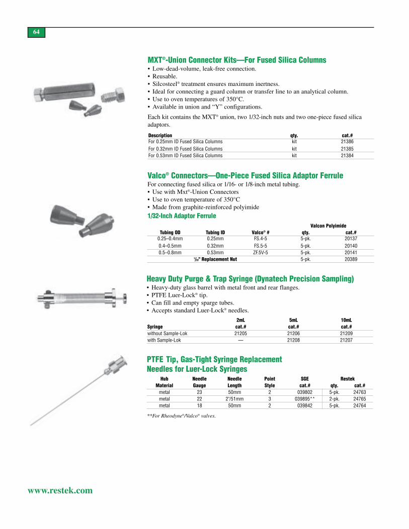
201375-pk.FS.4-50.25mm0.25–0.4mm
21386kitFor 0.25mm ID Fused Silica Columns
64
www.restek.com
MXT®-Union Connector Kits—For Fused Silica Columns• Low-dead-volume, leak-free connection.• Reusable.• Silcosteel® treatment ensures maximum inertness.• Ideal for connecting a guard column or transfer line to an analytical column.• Use to oven temperatures of 350°C.• Available in union and “Y” configurations.
Each kit contains the MXT® union, two 1/32-inch nuts and two one-piece fused silicaadaptors.
Description qty. cat.#
For 0.32mm ID Fused Silica Columns kit 21385For 0.53mm ID Fused Silica Columns kit 21384
Valco® Connectors—One-Piece Fused Silica Adaptor FerruleFor connecting fused silica or 1/16- or 1/8-inch metal tubing.• Use with Mxt®-Union Connectors• Use to oven temperature of 350°C• Made from graphite-reinforced polyimide
Valcon PolyimideTubing OD Tubing ID Valco® # qty. cat.#
0.4–0.5mm 0.32mm FS.5-5 5-pk. 201400.5–0.8mm 0.53mm ZF.5V-5 5-pk. 20141
1/32" Replacement Nut 5-pk. 20389
Heavy Duty Purge & Trap Syringe (Dynatech Precision Sampling)• Heavy-duty glass barrel with metal front and rear flanges.• PTFE Luer-Lock® tip.• Can fill and empty sparge tubes.• Accepts standard Luer-Lock® needles.
2mL 5mL 10mLSyringe cat.# cat.# cat.#without Sample-Lok 21205 21206 21209with Sample-Lok — 21208 21207
PTFE Tip, Gas-Tight Syringe Replacement Needles for Luer-Lock Syringes
**For Rheodyne®/Valco® valves.
Hub Needle Needle Point SGE RestekMaterial Gauge Length Style cat.# qty. cat.#
metal 23 50mm 2 039802 5-pk. 24763metal 22 2"/51mm 3 039895** 2-pk. 24765metal 18 50mm 2 039842 5-pk. 24764
1/32-Inch Adaptor Ferrule

PSS Liners for PerkinElmer GCsID*/OD &
Length (mm)Similar toPE part #
cat.#ea.
cat.#5-pk.
cat.#25-pk.
PSS Split/Splitless (1mm ID)
1.0 ID4.0 OD x 86.2 N612-1006 20738 20741 —
65
www.restek.com
Pre-Cleaned Volatile Organic Analyte Sampling Vials• Container, liner and closure cleaned and assembled.• Clear or amber.• Open top caps.• PTFE faced 0.125" silicone septa.• Each case lot numbered.
Description qty. cat.#20mL Clear Pre-Cleaned VOA Vials 72-pk. 2179820mL Amber Pre-Cleaned VOA Vials 72-pk. 2179940mL Clear Pre-Cleaned VOA Vials 72-pk. 2179640mL Amber Pre-Cleaned VOA Vials 72-pk. 21797
Leak Detective™ II Leak Detector• Affordable thermal conductivity leak detector—every analyst should have one.• Compact, ergonomic design is easy to hold and operate.• Detects helium, hydrogen, and nitrogen at 1x10⁻⁴cc/sec. or at an absolute concentration
as low as 100ppm.*• Fast results—responds in less than 2 seconds to trace leaks of gases with thermal con-
ductivities different than air.• Microchip design improves sensitivity and response time over previous models.• Auto zeroing with the touch of a button. • Battery-operated for increased portability (one 9-volt).
*Never use liquid leak detectors on a capillary system because liquids can be drawn into the column.Caution: NOT designed for determining leaks of combustible gases. A combustible gas detector shouldbe used for determining combustible gas leaks in possible hazardous conditions.
The compact, affordable tool that every analyst should have!Description qty. cat.#Leak Detective™ II Leak Detector ea. 20413
for Agilent/Finnigan GCsID**/OD &
Length (mm)cat.#ea.
cat.#5-pk.
1mm Split1.0 ID
6.3 OD x 78.5 20972 20973
for Shimadzu GCsID**/OD &
Length (mm)cat.#ea.
cat.#5-pk.
cat.#25-pk.
17A 1mm Split1.0 ID
5.0 OD x 95 20976 20977 20978
for Thermo Finnigan 8000 & TRACE Series GCsID**/OD &
Length (mm)Similar toTF Part #
cat.#ea.
cat.#5-pk.
1mm Split1.0 ID
8.0 OD x 105 453 20075 20916 20917
for Varian GCsID**/OD &
Length (mm)cat.#ea.
cat.#5-pk.
1mm Split1.0 ID
6.3 OD x 72 20970 20971We deactivate Restek liners using ourunique polymeric deactivation process toensure accurate chromatographic data. Weevaluate them with an endrin breakdowntest for complete inertness, and each lineris dimensionally checked for a perfect fit.Siltek™ and base deactivation are availablefor specialized analyses
010 %deactivated
all liners are
1mm ID Liners

66
www.restek.com
chlorobenzene-d51,4-dichlorobenzene-d4
fluorobenzene
8260A/B Internal Standard Mix
2,500µg/mL each in P&T methanol, 1mL/ampul
Each 5-pk. 10-pk.30241 30241-510 —
w/data pack30241-500 30241-520 30341
4-bromofluorobenzenedibromofluoromethane
1,2-dichloroethane-d4toluene-d8
8260A/B Surrogate Mix
2,500µg/mL each in P&T methanol, 1mL/ampul
Each 5-pk. 10-pk.30240 30240-510 —
w/data pack30240-500 30240-520 30340
4-Bromofluorobenzene
2,500µg/mL in P&T methanol, 1mL/ampul
Each 5-pk. 10-pk.30067 30067-510 —
w/data pack30067-500 30067-520 30167
10,000µg/mL in P&T methanol, 1mL/ampul
Each 5-pk. 10-pk.30082 30082-510 —
w/data pack30082-500 30082-520 30182
benzenechlorobenzene1,1-dichloroethene
toluenetrichloroethylene
8260B Matrix Spike Mix
2,500µg/mL each in P&T methanol, 1mL/ampul
Each 5-pk. 10-pk.30479 30479-510 —
w/data pack30479-500 30479-520 30579
perfluorotributylamine (PFTBA)
4-bromofluorobenzene
PFTBA (MS Tuning Compound)
1mL/ampul, neat
Each30482
acetone2-butanone
2-hexanone4-methyl-2-pentanone
VOA Calibration Mix #1 (ketones)
5,000µg/mL each in P&T methanol:water (90:10),1mL/ampul
Each 5-pk. 10-pk.30006 30006-510 —
w/data pack30006-500 30006-520 30106
acetonitrileacrylonitrileallyl chloridebenzenebromobenzenebromochloromethanebromodichloromethanebromoformn-butylbenzenesec-butylbenzenetert-butylbenzenecarbon disulfidecarbon tetrachloridechlorobenzene2-chloroethanolchloroformchloroprene2-chlorotoluene4-chlorotoluenedibromochloromethane1,2-dibromo-3-chloro-propane
1,2-dibromoethanedibromomethane1,2-dichlorobenzene1,3-dichlorobenzene1,4-dichlorobenzenecis-1,4-dichloro-2-butenetrans-1,4-dichloro-2-butene1,1-dichloroethane1,2-dichloroethane1,1-dichloroethenecis-1,2-dichloroethenetrans-1,2-dichloroethene1,2-dichloropropane1,3-dichloropropane2,2-dichloropropane1,1-dichloropropenecis-1,3-dichloropropene
trans-1,3-dichloropropenediethyl ether1,4-dioxaneethylbenzeneethyl methacrylatehexachlorobutadieneiodomethaneisobutyl alcoholisopropylbenzenep-isopropyltoluenemethacrylonitrilemethyl acrylatemethyl methacrylatemethylene chloridenaphthalenenitrobenzene2-nitropropanepentachloroethanepropionitrilen-propylbenzenestyrene1,1,1,2-tetrachloroethane1,1,2,2-tetrachloroethanetetrachloroethenetetrahydrofurantoluene1,2,3-trichlorobenzene1,2,4-trichlorobenzene1,1,1-trichloroethane1,1,2-trichloroethanetrichloroethene1,2,3-trichloropropane1,1,2-trichlorotrifluororethane(Freon® 113)
1,2,4-trimethylbenzene1,3,5-trimethylbenzenem-xyleneo-xylenep-xylene
8260B Calibration Mix #1(76 + 1 components)
Note: This product is provided as a two ampul set:
2,000µg/mL each in P&T methanol, 1mL/ampul
2-chloroethyl vinyl ether2,000µg/mL each in P&T methanol, 1mL/ampul
Each 5-pk. 10-pk.30475 30475-510 —
w/data pack30475-500 30475-520 30575
1,2-dichlorotetrafluoroethane (Freon® 114)
1,2-Dichlorotetrafluoroethane
2,000µg/mL in P&T methanol, 1mL/ampul
Each 5-pk. 10-pk.30476 30476-510 —
w/data pack30476-500 30476-520 30576
diisopropyl ether 2,000µg/mLethyl-tert-butyl ether 2,000tert-amyl methyl ether 2,000
tert-butyl alcohol 10,000methyl tert-butyl ether 2,000
California Oxygenates Mix
In P&T methanol, 1mL/ampul
Each 5-pk. 10-pk.30465 30465-510 —
w/data pack30465-500 30465-520 30565
ethanol
Ethanol Mix
10,000µg/mL in DI water, 1mL/ampul
Each 5-pk. 10-pk.30466 30466-510 —
w/data pack30466-500 30466-520 30566
acrolein
Acrolein Mix
10,000µg/mL in water, 1mL/ampul
Each 5-pk. 10-pk.30478 30478-510 —
w/data pack30478-500 30478-520 30578
vinyl acetateethyl acetateisopropyl acetate
n-propyl acetaten-butyl acetate
8260B Acetate Mix
2,000µg/mL each in P&T methanol, 1mL/ampul
Each 5-pk. 10-pk.30477 30477-510 —
w/data pack30477-500 30477-520 30577
n-amyl acetatebutyl acetateethyl acetateisopropyl acetate
methyl acetatepropyl acetatevinyl acetate
8260B Acetate Mix (Revised)
2,000µg/mL each in P&T methanol, 1mL/ampul
Each 5-pk. 10-pk.30489 30489-510 —
w/data pack30489-500 30489-520 30589
30005: VOA Matrix Spike Mix30042: 502.2 Calib. Mix #130043: 502.2 Calib. Mix #230044: 502.2 Calib. Mix #330045: 502.2 Calib. Mix #430046: 502.2 Calib. Mix #530047: 502.2 Calib. Mix #6
30067: 4-bromofluorobenzene30240: 8260A Surrogate Mix30241: 8260A InternalStandard Mix
30075: 8240/8260 SystemPerformance Check Mix
8260A Volatile Organics Kit
Contains 1mL each of these mixtures.
Kit Kit w/Data Pack30242 30242-500
Method 8260B
Method 8260A

67
www.restek.com
chlorobenzene-d51,4-dichlorobenzene-d4
1,4-difluorobenzenepentafluorobenzene
8260 Internal Standard Mix
2,500µg/mL each in P&T methanol, 1mL/ampul
Each 5-pk. 10-pk.30074 30074-510 —
w/data pack30074-500 30074-520 30174
4-bromofluorobenzenedibromofluoromethane
toluene-d8
8260 Surrogate Mix
2,500µg/mL each in P&T methanol, 1mL/ampul
Each 5-pk. 10-pk.30073 30073-510 —
w/data pack30073-500 30073-520 30173
bromoformchlorobenzenechloromethane
1,1-dichloroethane1,1,2,2-tetrachloroethane
8240/8260 System Performance Check Mix
2,000µg/mL each in P&T methanol, 1mL/ampul
Each 5-pk. 10-pk.30075 30075-510 —
w/data pack30075-500 30075-520 30175
chloroform1,1-dichloroethene1,2-dichloropropane
ethylbenzenetoluenevinyl chloride
8240/8260 Calibration Check Mix
2,000µg/mL each in P&T methanol, 1mL/ampul
Each 5-pk. 10-pk.30427 30427-510 —
w/data pack30427-500 30427-520 30527
30005: VOA Matrix Spike Mix30042: 502.2 Calib. Mix #130043: 502.2 Calib. Mix #230044: 502.2 Calib. Mix #330045: 502.2 Calib. Mix #430046: 502.2 Calib. Mix #530047: 502.2 Calib. Mix #6
30067: 4-bromofluorobenzene30073: 8260 Surrogate Mix30074: 8260 Internal Standard Mix
30075: 8240/8260 SystemPerformance Check Mix
8260 Volatile Organics Kit
Contains 1mL each of these mixtures.
Kit Kit w/Data Pack30076 30076-500
Method 8260
benzeneethylbenzenemethyl tert-butyl ethertoluene
m-xyleneo-xylenep-xylene
PVOC Mix (California)
1,000µg/mL each in P&T methanol, 1mL/ampul
Each 5-pk. 10-pk.30231 30231-510 —
w/data pack30231-500 30231-520 30331
benzeneethylbenzenemethyl tert-butyl ethernaphthalenetoluene
1,2,4-trimethylbenzene1,3,5-trimethylbenzenem-xyleneo-xylenep-xylene
PVOC/GRO Mix (Wisconsin)
1,000µg/mL each in P&T methanol, 1mL/ampul
Each 5-pk. 10-pk.30095 30095-510 —
w/data pack30095-500 30095-520 30195
benzeneethylbenzene3-methylpentanenaphthalene1,2,4-trimethylbenzene
2,2,4-trimethylpentane(isooctane)
toluenem-xyleneo-xylene
GRO Mix
1,000µg/mL each in P&T methanol, 1mL/ampul
Each 5-pk. 10-pk.30069 30069-510 —
w/data pack30069-500 30069-520 30169
CCoommppoonneenntt CCoonncc..,, ((µµgg//mmLL))benzene 500ethylbenzene 500heptane 5002-methylpentane 1500toluene 1500
CCoommppoonneenntt CCoonncc..,, ((µµgg//mmLL))1,2,4-trimethylbenzene 10002,2,4-trimethylpentane 1500m-xylene 1000o-xylene 1000p-xylene 1000
Gasoline Component Standard
10,000µg/mL total in P&T methanol, 1mL/ampul
Each 5-pk. 10-pk.30486 30486-510 —
w/data pack30486-500 30486-520 30586
benzene 500µg/mLethylbenzene 500heptane 5002-methylpentane 1,5001,2,4-trimethylbenzene 1,000
2,2,4-trimethylpentane 1,500toluene 1,500m-xylene 1,000o-xylene 1,000
GRO Mix (EPA)
In P&T methanol, 1mL/ampul
Each 5-pk. 10-pk.30065 30065-510 —
w/data pack30065-500 30065-520 30165
PVOC, GRO, & BTEX
benzeneethylbenzenetoluene
m-xyleneo-xylenep-xylene
BTEX Standard
200µg/mL each in P&T methanol, 1mL/ampul
Each 5-pk. 10-pk.30051 30051-510 —
w/data pack30051-500 30051-520 30151
2,000µg/mL each in P&T methanol, 1mL/ampul
Each 5-pk. 10-pk.30213 30213-510 —
w/data pack30213-500 30213-520 30313
2,000µg/mL each in P&T methanol, except m-xyleneand p-xylene at 1,000µg/mL, 1mL/ampul
Each 5-pk. 10-pk.30488 30488-510 —
w/data pack30488-500 30488-520 30588
benzeneethylbenzenetoluene
m-xyleneo-xylenep-xylene
BTEX Gas Mix
In nitrogen, 104 liters @ 1800psig
1ppm 100ppb34414 (ea.) 34428 (ea.)
CCeerrttiiffiieedd ffoorr::benzeneethylbenzeneisopropyl benzenemethyl tert-butyl ethernaphthalene
toluenem-xyleneo-xylenep-xylene
Certified BTEX in Unleaded Gas Composite Standard
5,500ppm gasoline in P&T methanol, 1mL/ampul
Each 5-pk. 10-pk.30237 30237-510 —
w/data pack30237-500 30237-520 30337

68
www.restek.com
bromodichloromethanebromoformchloroform1,2-dichlorobenzene1,3-dichlorobenzene1,4-dichlorobenzene1,2-dichloroethane
trans-1,2-dichloroethenecis-1,3-dichloropropenetrans-1,3-dichloropropeneethylbenzene1,1,2,2-tetrachloroethanetoluene1,1,1-trichloroethane
624 Calibration Mix #3
2,000µg/mL each in P&T methanol, 1mL/ampul
Each 5-pk. 10-pk.30022 30022-510 —
w/data pack30022-500 30022-520 30122
30020: 624 Calib. Mix #130021: 624 Calib. Mix #2
30022: 624 Calib. Mix #330023: 624 Int. Standard Mix
624 Kit
Contains 1mL each of these mixtures.
Kit Kit w/Data Pack30055 30055-500
benzenecarbon tetrachloridechlorobenzene2-chloroethyl vinyl etherdibromochloromethane1,1-dichloroethane
1,1-dichloroethene1,2-dichloropropanemethylene chloridetetrachloroethene1,1,2-trichloroethanetrichloroethene
624 Calibration Mix #2
2,000µg/mL each in P&T methanol, 1mL/ampul
Each 5-pk. 10-pk.30021 30021-510 —
w/data pack30021-500 30021-520 30121
30020: 624 Calib. Mix #130021: 624 Calib. Mix #230022: 624 Calib. Mix #3
30023: 624 Int. Standard Mix30243: 624 SurrogateStandard Mix
624 Complete Kit
Contains 1mL each of these mixtures.
Kit Kit w/Data Pack30244 30244-500
30042: 502.2 Calib. Mix #130021: 624 Calib. Mix #2
30022: 624 Calib. Mix #3
601/602 Purgeable Halocarbons Kit
Contains 1mL each of these mixtures.
Kit Kit w/Data Pack30061 30061-500
benzenechlorobenzene1,2-dichlorobenzene1,3-dichlorobenzene
1,4-dichlorobenzeneethylbenzenetoluene
602 Purgeable AromaticsCalibration Mix
2,000µg/mL each in P&T methanol, 1mL/ampul
Each 5-pk. 10-pk.30035 30035-510 —
w/data pack30035-500 30035-520 30135
Method 601 & 602
benzenebromobenzenebromochloromethanebromodichloromethanebromoformn-butylbenzenesec-butylbenzenetert-butylbenzenecarbon tetrachloridechlorobenzenechloroform2-chlorotoluene4-chlorotoluenedibromochloromethane1,2-dibromo-3-chloropropane1,2-dibromoethanedibromomethane1,2-dichlorobenzene1,3-dichlorobenzene1,4-dichlorobenzene1,1-dichloroethane1,2-dichloroethane1,1-dichloroethenecis-1,2-dichloroethenetrans-1,2-dichloroethene1,2-dichloropropane1,3-dichloropropane
2,2-dichloropropane1,1-dichloropropenecis-1,3-dichloropropenetrans-1,3-dichloropropeneethylbenzenehexachlorobutadieneisopropylbenzenep-isopropyltoluenemethylene chloridenaphthalenen-propylbenzenestyrene1,1,1,2-tetrachloroethane1,1,2,2-tetrachloroethanetetrachloroethenetoluene1,2,3-trichlorobenzene1,2,4-trichlorobenzene1,1,1-trichloroethane1,1,2-trichloroethanetrichloroethene1,2,3-trichloropropane1,2,4-trimethylbenzene1,3,5-trimethylbenzenem-xyleneo-xylenep-xylene
502.2 CAL2000 MegaMix™ Mixture
2,000µg/mL each in P&T methanol, 1mL/ampul
Each 5-pk. 10-pk.30431 30431-510 —
w/data pack30431-500 30431-520 30531
200µg/mL each in P&T methanol, 1mL/ampul
Each 5-pk. 10-pk.30432 30432-510 —
w/data pack30432-500 30432-520 30532
Method 502.2
1-chloro-2-fluorobenzene
1-Chloro-2-fluorobenzene
2,000µg/mL in P&T methanol, 1mL/ampul
Each 5-pk. 10-pk.30040 30040-510 —
w/data pack30040-500 30040-520 30140
2-bromo-1-chloropropane fluorobenzene
502.2 Internal Standard Mix #2
2,000µg/mL each in P&T methanol, 1mL/ampul
Each 5-pk. 10-pk.30041 30041-510 —
w/data pack30041-500 30041-520 30141
bromochloromethane2-bromo-1-chloropropane
1,4-dichlorobutane
624 Internal Standard Mix
1,500µg/mL each in P&T methanol, 1mL/ampul
Each 5-pk. 10-pk.30023 30023-510 —
w/data pack30023-500 30023-520 30123
Method 624
4-bromofluorobenzenefluorobenzene
pentafluorobenzene
624 Surrogate Standard Mix
2,000µg/mL each in P&T methanol, 1mL/ampul
Each 5-pk. 10-pk.30243 30243-510 —
w/data pack30243-500 30243-520 30343
1,4-bromofluorobenzene α,α,α-trifluorotoluene
Surrogate Standard
2,500µg/mL each in P&T methanol, 1mL/ampul
Each 5-pk. 10-pk.30484 30484-510 —
w/data pack30484-500 30484-520 30584
bromomethanechloroethanechloromethane
trichlorofluoromethanevinyl chloride
624 Calibration Mix #1
2,000µg/mL each in P&T methanol, 1mL/ampul
Each 5-pk. 10-pk.30020 30020-510 —
w/data pack30020-500 30020-520 30120

69
www.restekcorp.com
bromochloromethane1,4-difluorobenzene
chlorobenzene-d5VOA Internal Standard Mix
2,500µg/mL each in P&T methanol, 1mL/ampul
Each 5-pk. 10-pk.30011 30011-510 —
w/data pack30011-500 30011-520 30111
4-bromofluorobenzene1,2-dichloroethane-d4
toluene-d8
VOA Surrogate Spike Mix
2,500µg/mL each in P&T methanol, 1mL/ampul
Each 5-pk. 10-pk.30004 30004-510 —
w/data pack30004-500 30004-520 30104
benzenechlorobenzene1,1-dichloroethene
toluenetrichloroethene
VOA Matrix Spike Mix
2,500µg/mL each in P&T methanol, 1mL/ampul
Each 5-pk. 10-pk.30005 30005-510 —
w/data pack30005-500 30005-520 30105
benzeneethylbenzenetoluene
o-xylenep-xylene
VOA Screening Mix #1
1,000µg/mL each in P&T methanol, 1mL/ampul
Each 5-pk. 10-pk.30001 30001-510 —
w/data pack30001-500 30001-520 30101
n-dodecane n-nonaneVOA Screening Mix #2
1,000µg/mL each in P&T methanol, 1mL/ampul
Each 5-pk. 10-pk.30002 30002-510 —
w/data pack30002-500 30002-520 30102
4-bromofluorobenzeneVOA Tuning Compound
5,000µg/mL in P&T methanol, 1mL/ampul
Each 5-pk. 10-pk.30003 30003-510 —
w/data pack30003-500 30003-520 30103
perfluorotributylamine (PFTBA)
PFTBA (MS Tuning Compound)
1mL/ampul, neat
Each30482
bromochloromethane4-bromofluorobenzenechlorobenzene-d5
1,2-dichloroethane-d41,4-difluorobenzenetoluene-d8
CLP 04.1 VOA InternalStandard/SMC Spike Mix
2,500µg/mL each in P&T methanol, 1mL/ampul
Each 5-pk. 10-pk.30457 30457-510 —
w/data pack30457-500 30457-520 30557
04.2, 04.1, & 3/90 SOW
1-bromo-2-chloroethane1-chloro-3-fluorobenzene
fluorobenzene
8021/502.2 Surrogate Mix #1
2,000µg/mL each in P&T methanol, 1mL/ampul
Each 5-pk. 10-pk.30463 30463-510 —
w/data pack30463-500 30463-520 30563
1-bromo-2-chloroethane4-bromochlorobenzene
1-chloro-3-fluorobenzenefluorobenzene
8021/502.2 Surrogate Mix #2
2,000µg/mL each in P&T methanol, 1mL/ampul
Each 5-pk. 10-pk.30464 30464-510 —
w/data pack30464-500 30464-520 30564
30042: 502.2 Calib. Mix #130431: 502.2 CAL2000 MegaMix™
502.2 VOA Calib. Kit #2 (2000ppm)
Contains 1mL each of these mixtures.
Kit Kit w/Data Pack30445 30445-500
30439: 502.2 Calib. Mix #1A30432: 502.2 CAL200 MegaMix™
502.2 VOA Calib. Kit #3 (200ppm)
Contains 1mL each of these mixtures.
Kit Kit w/Data Pack30446 30446-500
bromomethanechloroethanechloromethane
dichlorodifluoromethanetrichlorofluoromethanevinyl chloride
502.2 Calibration Mix #1 (gases)
2,000µg/mL each in P&T methanol, 1mL/ampul
Each 5-pk. 10-pk.30042 30042-510
w/data pack30042-500 30042-520 30142
bromomethanechloroethanechloromethane
dichlorodifluoromethanetrichlorofluoromethanevinyl chloride
502.2 Calibration Mix #1A
200µg/mL each in P&T methanol, 1mL/ampul
Each 5-pk. 10-pk.30439 30439-510 —
w/data pack30439-500 30439-520 30539
UDID KNOW?
Restek reference materialsinclude a silanized vial for
sample transfer.

70
www.restek.com
bromodichloromethanebromoformdibromochloromethane1,2-dichloroethanecis-1,2-dichloroethenetrans-1,2-dichloroethene
cis-1,3-dichloropropenetrans-1,3-dichloropropenestyrene1,1,2,2-tetrachloroethanetetrachloroethene1,1,1-trichloroethane
VOA Calibration Mix #4
2,000µg/mL each in P&T methanol, 1mL/ampul
Each 5-pk. 10-pk.30009 30009-510 —
w/data pack30009-500 30009-520 30109
30001: VOA Screening Mix #130002: VOA Screening Mix #230003: VOA Tuning Comp.30004: VOA Surr. Spike Mix30005: VOA Matrix Spike Mix30006: VOA Calib. Mix #1(ketones)
30010: VOA Calib. Mix #5(gases)
30011: VOA Int’l Standard Mix30438: CLP VOA CAL2000MegaMix™
CLP Volatile Organics Kit #2
Contains 1mL each of these mixtures.
Kit Kit w/Data Pack30440 30440-500
30001: VOA Screening Mix #130002: VOA Screening Mix#230003: VOA Tuning Comp.30004: VOA Surr. Spike Mix30005: VOA Matrix Spike Mix30006: VOA Calib. Mix #1(ketones)
30007: VOA Calib. Mix #230008: VOA Calib. Mix #330009: VOA Calib. Mix #430010: VOA Calib. Mix #5(gases)
30011: VOA Internal Standard Mix
Volatile Organics Kit
Contains 1mL each of these mixtures.
Kit Kit w/Data Pack30050 30150
benzenebromodichloromethanebromoformcarbon disulfidecarbon tetrachloridechlorobenzenechloroformdibromochloromethane1,1-dichloroethane1,2-dichloroethane1,1-dichloroethenecis-1,2-dichloroethenetrans-1,2-dichloroethene1,2-dichloropropane
cis-1,3-dichloropropenetrans-1,3-dichloropropeneethylbenzenemethylene chloridestyrene1,1,2,2-tetrachloroethanetetrachloroethenetoluene1,1,1-trichloroethane1,1,2-trichloroethanetrichloroethenem-xyleneo-xylenep-xylene
CLP VOA CAL2000 MegaMix™ Mixture (29 components)Note: This product is provided as a two-ampul set:
2,000µg/mL each in P&T methanol, 1mL/ampul
vinyl acetate2,000µg/mL each in P&T methanol, 1mL/ampul
Each 5-pk. 10-pk.30438 30438-510 —
w/data pack30438-500 30438-520 30538
30006: VOA Calibration Mix #1 (ketones)30010: VOA Calibration Mix #5 (gases)30438: CLP VOA CAL2000 MegaMix™
CLP VOA Calibration Kit #2
Contains 1mL each of these mixtures.
Kit Kit w/Data Pack30442 30442-500
bromomethanechloroethane
chloromethanevinyl chloride
VOA Calibration Mix #5 (gases)
2,000µg/mL each in P&T methanol, 1mL/ampul
Each 5-pk. 10-pk.30010 30010-510 —
w/data pack30010-500 30010-520 30110
benzenecarbon disulfideethylbenzenetoluene
vinyl acetateo-xylenep-xylene
VOA Calibration Mix #2
2,000µg/mL each in P&T methanol, 1mL/ampul
Each 5-pk. 10-pk.30007 30007-510 —
w/data pack30007-500 30007-520 30107
carbon tetrachloridechlorobenzenechloroform1,1-dichloroethane1,1-dichloroethene
1,2-dichloropropanemethylene chloride1,1,2-trichloroethanetrichloroethenem-xylene
VOA Calibration Mix #3
2,000µg/mL each in P&T methanol, 1mL/ampul
Each 5-pk. 10-pk.30008 30008-510 —
w/data pack30008-500 30008-520 30108
3/90 SOW

71
www.restek.com
bromomethanechloroethanechloromethane
dichlorodifluoromethanetrichlorofluoromethanevinyl chloride
502.2 Calibration Mix #1 (gases)
2,000µg/mL each in P&T methanol, 1mL/ampul
Each 5-pk. 10-pk.30042 30042-510
w/data pack30042-500 30042-520 30142
bromomethanechloroethanechloromethane
dichlorodifluoromethanetrichlorofluoromethanevinyl chloride
502.2 Calibration Mix #1A
200µg/mL each in P&T methanol, 1mL/ampul
Each 5-pk. 10-pk.30439 30439-510 —
w/data pack30439-500 30439-520 30539
30006: VOA Calibration Mix #1 (ketones)30042: 502.2 Calibration Mix #1 (gases)30456: CLP 04.1 VOA CAL2000 MegaMix™
CLP 04.1 VOA Kit #3
Contains 1mL each of these mixtures.
Kit Kit w/Data Pack30460 30460-500
benzenebromochloromethanebromodichloromethanebromoformcarbon disulfidecarbon tetrachloridechlorobenzenechloroformcyclohexanedibromochloromethane(chlorodibromomethane)
1,2-dibromo-3-chloropropane1,2-dibromoethane (EDB)1,2-dichlorobenzene1,3-dichlorobenzene1,4-dichlorobenzene1,1-dichloroethane1,2-dichloroethane1,1-dichloroethylenecis-1,2-dichloroethylenetrans-1,2-dichloroethylene1,2-dichloropropanecis-1,3-dichloropropene(Z)
trans-1,3-dichloropropene (E)ethylbenzeneisopropylbenzene (cumene)methyl acetatemethylcyclohexanemethyl tert-butyl ether (MTBE)methylene chloride(dichloromethane)
styrene1,1,2,2-tetrachloroethanetetrachloroethylenetoluene1,2,3-trichlorobenzene1,2,4-trichlorobenzene1,1,1-trichloroethane1,1,2-trichloroethanetrichloroethylene1,1,2-trichlorotrifluoroethane(Freon® 113)
m-xyleneo-xylenep-xylene
OLC 03.2 VOA MegaMix™ Mixture(42 components)
2,000µg/mL each in P&T methanol, 1mL/ampul
Each 5-pk. 10-pk.30492 30492-510 —
w/data pack30492-500 30492-520 30592
NNoonn-KKeettoonneess::benzene-d6bromoform-dchloroethane-d5chloroform-d1,2-dichlorobenzene-d41,2-dichloroethane-d4
1,1-dichloroethene-d21,2-dichloropropane-d6trans-1,3-dichloropropene-d41,1,2,2-tetrachloroethane-d2toluene-d8vinyl chloride-d3
OLC 03.2 VOA DeuteratedMonitoring Compounds (DMC)(14 components)
EPA Contract Lab Program (CLP)Statement of Work (SOW) OLC03.2 is ananalytical method for the detection of lowconcentration volatile, semivolaitle, andpesticide/Arclor® organics in aqueous sam-ples. For VOA and SVOA GC/MS analysisOLC03.2 introduces Deuterated MonitoringCompounds (DMCs) as a sample-by-sam-ple accuracy indicator.
100µg/mL each in P&T methanol, 1mL/ampul
Note: This product is provided as a two-ampule set:
KKeettoonneess::2-butanone-d5 2-hexanone-d5200µg/mL each in P&T methanol, 0.5mL/ampul
Each 5-pk.30493 30493-510
benzenebromodichloromethanebromoformcarbon disulfidecarbon tetrachloridechlorobenzenechloroform1,2-dibromo-3-chloropropanecyclohexanedibromochloromethane1,2-dibromoethane1,2-dichlorobenzene1,3-dichlorobenzene1,4-dichlorobenzene1,1-dichloroethane1,2-dichloroethane1,1-dichloroethenecis-1,2-dichloroethenetrans-1,2-dichloroethene1,2-dichloropropanecis-1,3-dichloropropene
trans-1,3-dichloropropeneethylbenzeneisopropylbenzenemethyl acetatemethylcyclohexanemethylene chloridestyrenemethyl tert-butyl ether (MTBE)1,1,2,2-tetrachloroethanetetrachloroethenetoluene1,2,4-trichlorobenzene1,1,1-trichloroethane1,1,2-trichloroethanetrichloroethylene1,1,2-trichlorotrifluoroethane(Freon® 113)
m-xyleneo-xylenep-xylene
CLP 04.1 VOA CAL2000MegaMix™ Mixture (40 components)
2,000µg/mL each in P&T methanol, 1mL/ampul
Each 5-pk. 10-pk.30456 30456-510 —
w/data pack30456-500 30456-520 30556
04.2 & 04.1 SOW
Can’t locate theexact mixture
you need?With thousands of com-pounds in our inventory,
we can make any mixtureto your specifications.

PATENTS & TRADEMARKSRestek patents and trademarks are the property of Restek Corporation. Other trademarks appearing in Restek literature or on its website are the property of their respective owners. The Restek registered trademarks used here are registered in the United States and may also be registered in other countries.
Restek U.S. • 110 Benner Circle • Bellefonte, PA 16823 • 1-814-353-1300 • 1-800-356-1688 • fax: 1-814-353-1309 • www.restek.comRestek France • phone: +33 (0)1 60 78 32 10 • fax: +33 (0)1 60 78 70 90 • e-mail: [email protected] GmbH • phone: +49 (0)6172 2797 0 • fax: +49 (0)6172 2797 77 • e-mail: [email protected] Ireland • phone: +44 (0)2890 814576 • fax: +44 (0)2890 814576 • e-mail: [email protected] Japan • phone: +81 (3)6459 0025 • fax: +81 (3)6459 0025 • e-mail: [email protected] Restek U.K. LTD • phone: +44 (0)1494 563377 • fax: +44 (0)1494 564990 • e-mail: [email protected]
Lit. Cat.# 59887B© 2003 Restek Corporation. All rights reserved.
Printed in the U.S.A.