optimizing repulsive lorentz forces for a levitating
TRANSCRIPT
© 2015 IEEJ
IEEJ Journal of Industry Applications, Vol. 4, No. 4, pp. 439-444, June 2015
Optimizing Repulsive Lorentz Forces for a Levitating Induction Cooker
C. Zingerli,T. Nussbaumer,J. W. Kolar
This material is published in order to provide access to research results of the Power Electronic Systems Laboratory / D-ITET / ETH Zurich. Internal or personal use of this material is permitted. However, permission to reprint/republish this material for advertising or promotional purposes or for creating new collective works for resale or redistribution must be obtained from the copyright holder. By choosing to view this document, you agree to all provisions of the copyright laws protecting it.

IEEJ Journal of Industry ApplicationsVol.4 No.4 pp.439–444 DOI: 10.1541/ieejjia.4.439
Paper
Optimizing Repulsive Lorentz Forces for a Levitating Induction Cooker
Claudius M. Zingerli∗a)Non-member, Thomas Nussbaumer∗∗ Non-member
Johann W. Kolar∗ Non-member
(Manuscript received Aug. 12, 2014, revised Jan. 29, 2015)
In this paper, we present a novel way of induction cooking. Traditionally, an alternating magnetic field is used toinduce currents in a ferromagnetic pan to heat foods. We use nonferromagnetic materials and optimize the design forhigh repulsive forces in order to levitate the pan while simultaneously heating it and its contents. We use a simulation-based approach to study the influence of different parameters and to perform multidimensional analyses for the highforce versus the power or loss goals. Finally, an experimental prototype is realized and successfully operated.
Keywords: magnetic levitation, modeling, eddy currents, induction motors, induction cooking, home appliances
1. Motivation
The proliferation of induction cookers is constantly grow-ing. Compared to traditional electrical stoves, quick reac-tion time and — depending on the source — high energy effi-ciency speak for them (1). In a typical induction cooker, a flatinduction coil creates an alternating magnetic field. The fieldinduces a current flow in the conducting pan on top of thecoil (2). This leads to losses in the pan caused by its electricalresistance, heating up the pan and its contents. The currentsin the two coupled coils (excitation coil and pan) also have aforce effect. In this publication, we investigate if these forcescan be used to levitate the pan. Further, we study design vari-ants targeting stable levitation and concentration of the lossesin the pan and keep them away from the excitation — or bear-ing — coil(s). A design variant is shown in Fig. 1.
While newer developments (3) (4) override this restriction, inconventional induction stoves the base of the pan must typi-cally contain ferromagnetic material. Such materials conductthe magnetic field well and concentrate the magnetic flux.This primarily leads to a lower skin depth (higher resistance)as well as to a reduction of the flux path and consequentlyto an attracting force owing to the reduced reluctance. Thecurrent flow in the base of the pan is opposed to the one inthe excitation coil, why a repulsive force is created (Lorentzforce). The minimization of this force is often the goal ofoptimizations in applications like metal production (5). In ourinvestigation, we follow a completely different approach: thatof maximizing Lorentz forces in order to allow the pan to lev-itate so that an observer may witness an air gap between theexcitation/cooktop surface and the pan.
Generally, high excitation currents lead to high repulsiveforces. But there are limits on the excitation current because
a) Correspondence to: Claudius M. Zingerli. E-mail: [email protected]∗ ETH Zurich, Power Electronic Systems Laboratory
Physikstrasse 3, 8092 Zurich, Switzerland∗∗ Levitronix GmbH
Technoparkstrasse 1, 8005 Zurich, Switzerland
Fig. 1. Design variant of a levitated induction cooker
the removal of ohmic losses in the excitation coil becomesmore and more challenging. Thus, one criterion for optimiza-tion is to maximize the quotient of the losses in the pan ver-sus the losses in the excitation coil. A further criterion is themaximization of the bearing force at a certain loss level.
To simplify the construction, solely repulsive magneticfields shall be used. Additionally, no parts shall be added tothe pan (permanent magnets, coils, back iron). For this rea-son, active, top or radially acting magnetic bearing designswill not be considered.
2. Previous Works
The principle involved in using eddy currents for heatingand levitation is not new. Previous works include applica-tions on contactlessly melt metals (6) and many educationalexhibits. We use an eddy current bearing in one of our lec-tures to demonstrate a very simple magnetic bearing wherethe levitated object gets very hot quickly. In science and tech-nology museums one can often find an exhibit with a levitat-ing aluminum ring on top of a coil connected to the mains (7) (8).
What is new about our device is that we want to apply said
c© 2015 The Institute of Electrical Engineers of Japan. 439

Lorentz Forces optimized for a Levitating Induction Cooker(Claudius M. Zingerli et al.)
principle for cooking such as a demonstration of induction oras a show effect.
3. Analysis
The shape of the pan has a great influence on the force de-velopment. The strongest vertical forces (high axial stiffness)act on surfaces orthogonal to the coil axis, but these surfacescause no radial stiffness; therefore, a pan consisting solelyof such surfaces (e.g. a sheet) would simply slip out and falldown. On the other hand, a spherically shaped pan offers apositive radial stiffness but, despite the tendency to right it-self, it has a zero tilting stiffness. A flat bowl/plate shapedpan offers a positive axial, radial and tilting stiffness and isthus researched.
For an efficient excitation, the excitation coil is operatedin a (series) resonant circuit. As the pan moves, the induc-tance changes and hence, the resonant frequency. Experi-ments have shown that without any extra means of damping,the levitated pan would oscillate and eventually touch the coilsurface or even fall out. We adaptively control the excitationfrequency by tracking the coil current.
Assuming that the major part of the flux in the excitationcoil induces a current in the pan and that the pan is thickenough to shield the field, an increase of the coil radius leadsto an increase of the current in the pan and — at a constant airgap field strength — to a proportional increase of the Lorentzforce acting on the pan.
At a fixed geometry and air gap, the coupling between ex-citation and pan is constant. A higher excitation current thenleads to a proportionally higher magnetic air gap field andcurrent in the pan. The Lorentz force acting on the pan isproportional to the current in the pan and air gap flux densitywhich is again proportional to the air gap field. Therefore thisforce should increase with the excitation current squared.
4. Simulation
To verify the feasibility of the concept and to optimize thedesign, a simulative approach has been chosen. Due to therotational symmetry, all simulations were 2D FEM-based ina cylindrical coordinate system in the eddy current domain.All dimensions were parameterized in order to allow vari-ation and tuning runs, since with today’s computer power,multidimensional searches could be performed within onlyhours (for example frequency versus coil diameter and panthickness).
Figure 2 shows the simulation model used for a simplecylindrical pan. The mesh in the levitated object (Pan) wasmanually adjusted to include multiple elements in the mate-rial thickness. The trapezoidal shape of the coil allows fora high winding density and does not require additional sup-ports.
The coil below was excited with a fixed amplitude AC cur-rent. This constant current excitation was used because inthe experiment the number of turns and maximum amplifiercurrent are fixed while independent of the inductance, the res-onant tank can always be tuned to push the voltage amplitudehigh enough to drive that current.
As expected, the following proportionalities of the re-pelling force F were confirmed:
Fig. 2. Model of a magnetically levitated inductioncooker. The vertical (z) axis shows the rotational sym-metry. The excitation coil is stranded and supplied with afixed amplitude AC current
Fig. 3. Simulated force F as a function of the excitationcoil radius ri at different pan radii rpan (flat aluminum pan,iexc = 1000 A · turns, Δz = 33 mm, radial excitation coilthickness: 20 mm)
F ∝ ri Inner coil radius ri
∝ i2exc Ampere turns iexc of excitation∝ cos(α) Pan wall angle α∝ 1/Δz Vertical distance Δz between exci-
tation coil center and pan
These proportionalities are not necessarily universal, but ap-ply to the dimensions and currents studied and shown in thefigures of this paper.
Figure 3 shows that the repelling force acting on the panrises proportionally to the excitation coil radius. If the panis smaller than the excitation coil, the force starts to decreaseagain, so matched pan and coil sizes are important.
Good conducting materials (Al, Cu) lead to repulsiveforces with little dependency on fexc (Fig. 4). The forces aresimilar in both materials, but aluminum being about threetimes lighter than copper, the air gap will be wider at thesame current. Iron (Fe-1010) reveals a strong dependencyon fexc in the studied frequency range, even showing attract-ing forces when remanence dominates at frequencies below12 kHz. Due to the high resistivity of iron, the force versusheating power quotient is also low.
In Fig. 5, the dependence of the force on the excitation fre-quency fexc and the pan thickness d is shown. The highestrepelling force is generated with a pan thickness of about 4/7
440 IEEJ Journal IA, Vol.4, No.4, 2015

Lorentz Forces optimized for a Levitating Induction Cooker(Claudius M. Zingerli et al.)
Fig. 4. Force F as a function of excitation frequencyfexc at different pan materials (iexc = 500 A · turns, Δz =40 mm, ri = 50 mm). Aluminum and copper show no sig-nificant difference, while iron generally generates lowerrepulsive forces, yet (at low frequencies) produces at-tracting forces
Fig. 5. Force F as a function of the pan thickness d atdifferent excitation frequencies fexc (iexc = 500 A · turns,Δz = 40 mm, ri = 50 mm, aluminum pan). At low fre-quencies (< 30 kHz) a force maximum can be found neard = 4/7 · δ with the skin depth δ
of the corresponding skin depth. This finding has been testedagainst different materials (Aluminum, Copper and Magne-sium) and frequencies ( fexc = 1 kHz...100 kHz). If the pan isthinner, the force decreases rapidly. If the pan is thicker, thedecrease is less. At a constant excitation current, however,the heating power rises fast, hence, depending on the appli-cation — heating power versus levitation — an optimum canbe found.
Studies on the influence of the excitation current iexc
and levitation height Δz at two different coil radii ri =
{50 mm, 100 mm} were performed (Figs. 6 and 7). While inboth designs, the force increases with the current squared, thesmaller coil only allows for levitated loads in a low range,even at higher currents or small gaps.
The decreasing force with increasing gap size Δz (Fig. 8)can be approximated by a hyperbolic curve 1/Δz. The de-crease is due to the smaller coupling which eventually leadsto less ohmic losses in the levitated pan than in the excitation
Fig. 6. Simulated force F as a function of the excitationcurrent iexc at different gaps Δz (ri = 50 mm)
Fig. 7. Simulated force F as a function of the excitationcurrent iexc at different gaps Δz (ri = 100 mm)
Fig. 8. Simulated force F as a function of the air gap Δzat different excitation currents iexc (ri = 50 mm, fexc =10 kHz)
coil at high distances (Fig. 9). In the range studied, the lossdistribution is solely a function of the geometry, independentof the electrical excitation.
To give an example, levitating a load of m = 3 kg (Typ-ical caquelon pan and fondue contents for a party of four),using a coil with an inner radius of ri = 100 mm, at a level of
441 IEEJ Journal IA, Vol.4, No.4, 2015
Lorentz Forces optimized for a Levitating Induction Cooker(Claudius M. Zingerli et al.)
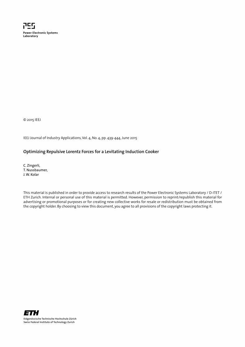
Fig. 9. Simulated ohmic losses in the pan at iexc =1000 A · T. The loss ratio pan/excitation goes below oneat wider air gaps Δz (ri = 50 mm, fexc = 10 kHz)
Δz = 10 mm, needs a current of iexc = 2 kA · turns. This cur-rent produces ohmic losses on the pan of P = 1.5 kW whichis assumed sufficient for cooking applications.
5. Experiment
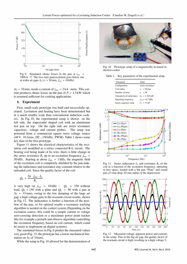
First, small-scale prototype was built and successfully op-erated. Levitation and heating have been demonstrated butat a much smaller scale than conventional induction cook-ers. In Fig. 10, the experimental setup is shown: on theleft side, the trapezoidal shaped coil with an aluminiumtest pan on top. On the right side are series resonancecapacitors, voltage and current probes. The setup waspowered from a commercial square wave voltage source(48 V, 10 Arms, DC...150 kHz, PWM). Table 1 shows somekey data of the first prototype.
Figure 11 shows the electrical characteristics of the exci-tation coil modelled as a series connected R-L circuit. Thebearing coil being made of liz wire, there is little change inthe series resistance Rs up to an excitation frequency fexc =
50 kHz. Starting at about fexc = 1 kHz, the magnetic fieldof the excitation coil is completely shielded by the pan mak-ing the inductance and resistance stay constant relative to theunloaded coil. Since the quality factor of the coil
QL =2π · fexc · Ls
Rs
is very high (at fexc = 18 kHz : QL = 350 withoutload, QL = 150 with a plate and QL = 90 with a pan atΔz = 33 mm), owing to the low damping of the large airgap, a high voltage gain in the resonant circuit results, shownin Fig. 12. The inductance is further a function of the posi-tion of the pan, so for optimal results a resonance trackingalgorithm is needed on the control system (Depending on theexcitation source, this could be a simple current or voltagezero-crossing detection or a maximum power point trackerlike for example a perturb and observe-algorithm controllingthe excitation frequency based on coil current, which couldbe easier to implement on digital systems).
The simulated forces in Fig. 6 predict the measured valuesvery good (Fig. 13, the prototype has a lower mechanical lim-itation on Δz of 33mm).
While the setup in Fig. 10 allowed for the demonstration of
Fig. 10. Prototype setup of a magnetically levitated in-duction cooker
Table 1. Key parameters of the experimental setup
Parameter Value
Configuration series resonance
Coil radius ri = 50 mm
Number of turns n = 99
Unloaded coil inductance L0 = 1.245 mH
Operating frequency fexc= 16.7 kHz
Series capacitor value Cs = 73 nF
Fig. 11. Series inductance Ls and resistance Rs of thecoil as a function of the excitation frequency, operatingin free space, loaded with a flat pan “Plate” and roundpan (21 mm deep, 92 mm radius of the depression)
Fig. 12. Measured voltage, apparent power and currentsin the setup. Due to the big air gap, the quality factor ofthe resonant circuit is high, resulting in a high voltage Vc
442 IEEJ Journal IA, Vol.4, No.4, 2015

Lorentz Forces optimized for a Levitating Induction Cooker(Claudius M. Zingerli et al.)
Fig. 13. Force F as a function of the excitation currentiexc normalized to one turn at different gaps (Δz) compar-ing measured and simulated values (sim)
(a) Bottom view
(b) Top view
Fig. 14. Improved prototype for cooking demonstra-tions (ri = 200 mm, Δz ≈ 30 mm). The edge of the alu-minium pan is M-shaped for high radial and tilting stiff-ness
a stable axial bearing, to improve radial force and returningtilting torque for levitated cooking, the usage a of a pan withan M-shaped edge is recommended, as shown in Fig. 14.
6. Discussion
To achieve a big air gap (a high levitation level), high ex-citation currents are needed (F ∝ i2exc/Δz for gaps Δz � di-ameter), which inherently lead to an elevated heating power.If this power is not needed the current has to be reduced andthe gap will become smaller with the levitation effect beingless apparent.
High excitation currents also lead to high losses in the ex-citation coil that have to be dealt with. While, in a conven-tional induction cooker, the excess heat from the excitationcoil can be dumped into the pan to limit the coil’s tempera-ture to the pan’s, this cannot easily be done here because of
the weak thermal coupling between pan and excitation coilduring levitation. We presume that an active (fan based) cool-ing of the excitation coil can hardly be avoided.
The repulsive force between excitation coil and prototypepan is quite small for cooking applications: as a result,heavier or bigger pans cannot be levitated without increas-ing excitation current and heating power to very high lev-els. Simulations of a bigger model were performed (Fig. 7,ri = 100 mm). At bigger radii and excitation currents orsmaller air gaps, significantly higher forces can be reached,but there are at least two downsides: First, the force onlyincreases linearly with the radius, while the weight of thepan generally scales by volume, radius at the power of three.Second, simple air cooling of the excitation coil can only beperformed at the coil surface which scales with the radiussquared, so cooling of bigger coils or higher currents will be-come challenging.
The simple construction has the further disadvantage oflow stiffness compared to actively controlled, PM-based orattracting magnetic bearings, which could be disadvanta-geous in relation to external disturbance forces (stirring,adding or removing material from the pan).
7. Conclusions and Outlook
It has been shown that levitating a pan on an inductioncooker is not only feasible, but can also be realized, be itas a small prototype or a typically sized pan including con-tents. The heating power is coupled to the repulsive forceand is generally quite high. To increase the force-to-powerquotient, the application of permanent magnet or reluctancebased passive and active magnetic bearings should be stud-ied.
Currently, the design is rotationally symmetric. Similar toan induction motor, further coils could be added to create arotating magnetic field in order to spin the levitated pan. Thelifting and driving fields could further be superimposed onthe control circuit to allow for a simpler construction withfewer coils.
By using position sensors or applying one of the severalpublished approaches for sensor-less control, an active con-trol circuit could be realized to enhance the stiffness of thebearing including axial, tilting and radial movement. Whilethe first do not need any additional coils, control of the lateraxes asks for independent control by e.g. the coils of thedrive.
The current design has the advantage of boosting the heat-ing power the closer the pan gets to the excitation coil. Ifthere is less material in the pan (for example due to evapora-tion, boiling or removal), the gap is widened: this results in alower heating power proving a passively safe behavior. Giventhat power is not reduced to zero with an empty pan, how-ever, additional means of supervision are necessary, whichmay be implemented using a contactless IR-detector as pro-posed in (2).
While our main application is cooking and educational ex-hibits, the contactless nature of the system could just as wellbe used in very sensitive applications where for example vi-bration, contamination or temperatures must be separated be-tween heater and good.
443 IEEJ Journal IA, Vol.4, No.4, 2015

Lorentz Forces optimized for a Levitating Induction Cooker(Claudius M. Zingerli et al.)
AcknowledgmentThe authors would like to thank to Dimitri Keller, Sev-
erin Mayrhofer and Timon Kunzle for their work on an im-proved prototype design that has been successfully used forreal cooking demonstrations.
References
( 1 ) H. Koertzen, J. Van Wyk, and J. Ferreira: “Design of the half-bridge, seriesresonant converter for induction cooking”, in Power Electronics SpecialistsConference, 1995. PESC’95 Record., 26th Annual IEEE, Vol.2, pp.729–735(1995)
( 2 ) P.H. Peters: “A portable cool-surface induction cooking appliance”, IEEETrans. Ind. Appl., Vol.IA-10, No.6, pp.814–822 (1974)
( 3 ) A. Fujita, H. Sadakata, I. Hirota, H. Omori, and M. Nakaoka: “Latestdevelopments of high-frequency series load resonant inverter type built-incooktops for induction heated all metallic appliances”, in Power Electronicsand Motion Control Conference, 2009. IPEMC’09. IEEE 6th International,pp.2537–2544 (2009)
( 4 ) Y. Kawaguchi, E. Hiraki, T. Tanaka, H.S.A. Fujita, H. Omori, andM. Nakaoka: “Two-stage soft-switching high-frequency inverter with simplepfc function for consumer ih cooking appliances”, IEEJ Trans. IA, Vol.130,pp.450–458 (2010)
( 5 ) S. Hosseini, A. Kashtiban, and G. Alizadeh, “Particle swarm optimizationand finite-element based approach for induction heating cooker design”, inSICE-ICASE, 2006. International Joint Conference, pp.4624–4627 (2006)
( 6 ) E.C. Okress, D.M. Wroughton, C. Comenetz, P.N. Brace, and J.C.K. Kelly:“Electromagnetic levitation of solid and molten metals”, Journal of AppliedPhysics, Vol.23, p.545 (1952)
( 7 ) University of Illinois, Urbana-Champaign Engineering Open House: “Float-ing frying pan”, March 2007. [Online]. Available: http://eoh.ec.uiuc.edu/
( 8 ) Crealev Magnetic Levitation Technology, TSC Group: “Hovering cook-ing pan”, January 2012. [Online]. Available: http://www.youtube.com/watch?v=CMURy4AgZPA
Claudius M. Zingerli (Non-member) was born in Thal, Switzerlandin 1984. He received the Dipl.-Ing. degree (M.Sc.)in electrical engineering from the Swiss Federal In-stitute of Technology (ETH) Zurich, Zurich, Switzer-land, in 2009. During his studies, he did research onsensing and advanced control of magnetic bearingsfor high-speed electrical drive systems. He is cur-rently working toward the Ph.D. degree at the PowerElectronic Systems Laboratory (PES), Swiss FederalInstitute of Technology (ETH) Zurich in the area of
bearingless machines and drives. His main research interests include powerelectronics, converters, digital control and sensor systems.
Thomas Nussbaumer (Non-member) was born in Vienna, Austria,in 1975. He received the M.Sc. degree (Hons.) inelectrical engineering from the University of Tech-nology Vienna, Vienna, in 2001, and the Ph.D. de-gree from the Power Electronic Systems (PES) Lab-oratory, Swiss Federal Institute of Technology (ETH)Zurich, Zurich, Switzerland, in 2004. From 2001 to2006, he was with the PES, where he was involvedin research on modeling, design, and control of three-phase rectifiers, power factor correction techniques,
and electromagnetic compatibility. Since 2006, he has been with LevitronixGmbH, Zurich, where he is currently involved in research on bearingless mo-tors, magnetic levitation, and permanent-magnet motor drives for the semi-conductor and biotechnology industry. His current research is focused oncompact and high-performance mechatronic systems including novel powerelectronics topologies, control techniques, drive systems, sensor technolo-gies, electromagnetic interference, and thermal aspects.
Johann W. Kolar (Non-member) received his M.Sc. and Ph.D. de-grees (summa cum laude) from the University ofTechnology Vienna in 1997 and 1998, respectively.Since 1982 he has been working as an internationalconsultant in the fields of power electronics, indus-trial electronics and high performance drives. He iscurrently a Full Professor and the Head of the PowerElectronic Systems Laboratory at the Swiss FederalInstitute of Technology (ETH) Zurich. He has pro-posed numerous novel PWM converter topologies,
and modulation and control concepts, e.g., the Vienna Rectifier, the SwissRectifier, and the AC-AC Sparse Matrix Converter. Dr. Kolar has publishedover 550 scientific papers in international journals and conference proceed-ings and has filed more than 110 patents. He received 9 IEEE TransactionsPrize Paper Awards and 8 IEEE Conference Prize Paper Awards. The focusof his current research is on AC-AC and AC-DC converter topologies withlow effects on the mains, on the realization of ultra-compact/efficient con-verter modules employing latest power semiconductor technology (SiC andGaN), Power Supplies on Chip, multi-domain/scale modeling/simulationand multi-objective optimization, and ultra-high speed and bearingless mo-tors.
444 IEEJ Journal IA, Vol.4, No.4, 2015