optimizing dma data transfers for - imag.frmaler/papers/thesis-selma.pdf · not to be afraid of...
TRANSCRIPT

THÈSEPour obtenir le grade de
DOCTEUR DE L’UNIVERSITÉ DE GRENOBLESpécialité : Informatique
Arrêté ministérial :
Présentée par
Selma Saïdi
Thèse dirigée par Dr. Oded Maler
préparée au sein du laboratoire VERIMAGet de l’école doctorale Mathematiques, Sciences et Technologies del’Information, Informatique (MSTII)
Optimizing DMA Data Transfers forEmbedded Multi-Cores
Thèse soutenue publiquement le 24 Octobre 2012,devant le jury composé de :
Prof. Ahmed BouajjaniProfesseur à l ’université Paris diderot, PrésidentProf. Luca BeniniProfesseur à l ’université de Bologne, RapporteurDr. Albert CohenDirecteur de Recherche, INRIA, RapporteurDr. Oded MalerDirecteur de Recherche, CNRS, Directeur de thèseMr, Eric FlamandDirecteur de la division AST-Computing, STMicroelectronics, ExaminateurMr, Bruno JegoEquipe Application à AST-computing,STMicroelectronics, Examinateur

ii

“ The day you stop learning, you stop existing for me... ”
To the soul of my grand father, your quote is still engraved in our hearts and minds.
To my parents, Lalia and M’hamed, for your unconditional love and support, your unlimittedambition and trust.
1

2

Acknowledgments
Writing the following acknowledgments was a hard exercise, as it is hard to escape from therepetitive and ready to use expressions, commonly used in such contexts. I hope I have found in thefollowing the words to appropriately thank all the people who influenced me and the advancementof this thesis.
First, I would like to thank the members of the jury, Prof. Ahmed Bouajjani for offering mepreviously an internship in his research group, during my master and when I was at the doorstepof PhD, and now for chairing the jury which marks the end of my PhD. I would also like tothank my distinguished reviewers Prof. Luca Benini and Dr. Albert Cohen for the time they haveallocated to read and evaluate this work. I would like to thank Mr. Eric Flamand for the interesthe showed to this thesis by being a member of the jury, which hopefully reflects the potentialindustrial applicability of its results. I am very glad and proud I had such a jury.
Then, I would like to thank Oded Maler, my thesis supervisor, for a lot of things that are hardto enumerate but that I will try to summarize in the following. I want to thank him for his help,patience and support all along the way despite the numerous hurdles. I would like to thank himbecause he initiated me to research, and science in its broader meaning. Research, which wasfor me just an abstract idea before starting working with him, and that turned out to be a passionafterwards. I would like to thank him for his tremendous flexibility and availability, and for thegreat degree of freedom he gave me. Indeed, Oded always listened and showed respect for whatI had to say and the direction I wanted to pursue. This allowed me to tremendously develop bothmy autonomy and my ability to have a better feeling of what are the research topics that I like,understand and am able to work on. I also learnt with Oded how to believe in what you do andnot to be afraid of tackling problems far from your domain of expertise because science is aboutlearning everyday and that it is much much wider than the tiny sphere on which we are working.For all this and many other things, I am very grateful to him, for all the things he taught me, alwaysin a very good, fun and relaxed atmosphere of work.
More generally, I would like to thank all my colleagues in Verimag, I think Verimag is a verygood school to learn how to be a researcher, inspiring for young students. Thanks for all theinteresting discussions and support I had with everyone such as: Florence Maraninchi, MatthieuMoy, Susanne Graf, Pascal Lafourcade, Olivier Lebeltel, Scott Cotton, and Pranav Tendulkar whoplayed an important role in this thesis as he helped significantly in advancing the experimentalresults. I also would like to thank all the administrative stuff who is helping everyday. Finally, Iwould like to thank all the friends I made along the way and who supported me in so many ways:Noa Shalev, Julien Legriel, Jean-François Kempf, Imene Ben Hafaiedh, Claire Maiza and ChaoukiMaiza.
I think one of the main challenges of this thesis, was to find the right balance and harmonybetween the world of academia and the world of industry. I think I have succeeded to some extentin this direction. This would not have been possible without the help of Thierry Lepley who, on
3

ACKNOWLEDGMENTS
the way, took on his shoulders the industrial follow-up of this thesis. I would like to thank him forall the time he cut-off from his working days and dedicated to the long and numerous discussionswe had in order to identify a relevant industrial problem, and then follow up with the steps to solveit. Discussing with Thierry is always enriching and opens the door to interesting applied scientificproblems. I would like to thank him for all the things I learnt with him, for his excitement aboutthis work, that he has transmitted to me, for his continuous support and because he always believedthat this work can lead to interesting results. So thank you Thierry, I am really grateful to you.
Furthermore, I would like to thank all my colleagues in the AST-division in STMicroelectron-ics where I always felt welcomed, and where I learnt a lot about hardware and embedded software.I would like first to thank Bruno Jego, my manager in STMicroelectronics, for his continuous con-cern about the advancement of this thesis and for providing all the facilities for that. I would alsolike to thank Jean-Philippe Cousin, Jean-josé berenguer, Richard Hersemeule, Germain Hougou,Gilbert Richard, Iker DePoy, Bruno Galilee, khaldon Hassan, and Clement Leray, who always hadthe time to answer my numerous questions despite their very tight timing commitments.
Last but not least, I would like to thank the members of my family, in particular Hassen andLamis, for being so loving, supportive and inspiring. Hassen always knew how to provide me withthe right advices at the right moment and Lamis always had great ambitions and always dreamt ofa better life for both of us. I owe you a Lot ...
4 ACKNOWLEDGMENTS

Abstract
Multiprocessor system on chip (MPSoC) such as the CELL processor or the more recent Plat-form2012 are heterogeneous multi-core architectures, with a powerful host processor and a com-putation fabric, consisting of several smaller cores, whose intended role is to act as a generalpurpose programmable accelerator. Therefore computation-intensive (and parallelizable) parts ofthe application initially intended to be executed by the host processor are offloaded to the multi-cores for execution. These parts of the application are often data intensive, operating on largearrays of data initially stored in a remote off-chip memory whose access time is about 100 timesslower than that of the cores local memory. Accessing data in the off-chip memory becomes thena main bottleneck for performance. A major characteristic of these platforms is a software con-trolled local memory storage rather than a hidden cache mechanism where data movement in thememory hierarchy, typically performed using a DMA (Direct Memory Access) engine, are ex-plicitely managed by the software. In this thesis, we attempt to optimize such data transfers inorder to reduce/hide the off-chip memory latency.
RésuméLes systèmes multiprocesseurs sur puce, tel que le processeur CELL ou plus récemment Plat-
form 2012, sont des architectures multicœurs hétérogènes constitués d’un processeur host et d’unefabric de calcul qui consiste en plusieurs petits cœurs dont le rôle est d’agir comme un accéléra-teur programmable. Les parties parallélisable d’une application, qui initialement est supposé etreexecuté par le host, et dont le calcul est intensif sont envoyés a la fabric multicœurs pour être exé-cutés. Ces applications sont en général des applications qui manipulent des tableaux trés largesde données, ces données sont stockées dans une memoire distante hors puce (off-chip memory)dont l ’accès est 100 fois plus lent que l ’accès par un cœur a une mémoire locale. Accéder cesdonnées dans la mémoire off-chip devient donc un problème majeur pour les performances. unecharacteristiques principale de ces plateformes est une mémoire local géré par le software, au lieud un mechanisme de cache, tel que les mouvements de données dans la hiérarchie mémoire sontexplicitement gérés par le software. Dans cette thèse, l ’objectif est d’optimiser ces transfert dedonnées dans le but de reduire/cacher la latence de la mémoire off-chip .
5

ABSTRACT
6 ABSTRACT

Contents
1
Acknowledgments 3
Abstract 5
Contents 7
Introduction 9
1 Embedded Multicores: Opportunities and challenges 111.1 Embedded Multicore Architectures . . . . . . . . . . . . . . . . . . . . . . . . . 11
1.1.1 Multiprocessor Systems on chip (MPSoCs) . . . . . . . . . . . . . . . . 111.1.2 Example of an MPSoC: P2012 . . . . . . . . . . . . . . . . . . . . . . . 141.1.3 Memory Organization . . . . . . . . . . . . . . . . . . . . . . . . . . . 15
1.2 Embedded Software . . . . . . . . . . . . . . . . . . . . . . . . . . . . . . . . . 191.2.1 Parallelization potential of an application . . . . . . . . . . . . . . . . . 191.2.2 Parallelization . . . . . . . . . . . . . . . . . . . . . . . . . . . . . . . 201.2.3 Parallel programming . . . . . . . . . . . . . . . . . . . . . . . . . . . . 221.2.4 Deployment . . . . . . . . . . . . . . . . . . . . . . . . . . . . . . . . . 23
1.3 Conclusions . . . . . . . . . . . . . . . . . . . . . . . . . . . . . . . . . . . . . 24
2 Preliminaries 252.1 Introduction . . . . . . . . . . . . . . . . . . . . . . . . . . . . . . . . . . . . . 252.2 Direct Memory Access (DMA) Engines . . . . . . . . . . . . . . . . . . . . . . 25
2.2.1 Example of a DMA Command Flow . . . . . . . . . . . . . . . . . . . . 262.2.2 The DMA’s main features . . . . . . . . . . . . . . . . . . . . . . . . . 27
2.3 Data Parallel Applications . . . . . . . . . . . . . . . . . . . . . . . . . . . . . 292.3.1 Independent Data Computations . . . . . . . . . . . . . . . . . . . . . . 302.3.2 Overlapped Data Computations . . . . . . . . . . . . . . . . . . . . . . 322.3.3 Discussion . . . . . . . . . . . . . . . . . . . . . . . . . . . . . . . . . 33
2.4 Software Pipelining . . . . . . . . . . . . . . . . . . . . . . . . . . . . . . . . . 342.4.1 Buffering . . . . . . . . . . . . . . . . . . . . . . . . . . . . . . . . . . 342.4.2 Double Buffering . . . . . . . . . . . . . . . . . . . . . . . . . . . . . . 35
2.5 Choosing a Granularity of Transfers . . . . . . . . . . . . . . . . . . . . . . . . 36
3 Optimal Granularity for Data Transfers 393.1 Computations and Data Transfers Characterization . . . . . . . . . . . . . . . . 39
3.1.1 DMA Performance Model . . . . . . . . . . . . . . . . . . . . . . . . . 393.1.2 Computation Time . . . . . . . . . . . . . . . . . . . . . . . . . . . . . 41
7

CONTENTS
3.2 Problem Formulation . . . . . . . . . . . . . . . . . . . . . . . . . . . . . . . . 413.3 Optimal Granularity for Independent Computations . . . . . . . . . . . . . . . . 43
3.3.1 Single Processor . . . . . . . . . . . . . . . . . . . . . . . . . . . . . . 433.3.2 Multiple Processors . . . . . . . . . . . . . . . . . . . . . . . . . . . . . 453.3.3 Memory Limitation . . . . . . . . . . . . . . . . . . . . . . . . . . . . . 473.3.4 Conclusion . . . . . . . . . . . . . . . . . . . . . . . . . . . . . . . . . 48
4 Shared Data Transfers 514.1 Introduction . . . . . . . . . . . . . . . . . . . . . . . . . . . . . . . . . . . . . 514.2 Transferring Shared Data in one-dimensional data . . . . . . . . . . . . . . . . . 51
4.2.1 Replication . . . . . . . . . . . . . . . . . . . . . . . . . . . . . . . . . 524.2.2 Inter-Processor Communication . . . . . . . . . . . . . . . . . . . . . . 534.2.3 Local Buffering . . . . . . . . . . . . . . . . . . . . . . . . . . . . . . . 544.2.4 Comparing Strategies . . . . . . . . . . . . . . . . . . . . . . . . . . . . 55
4.3 Optimal Granularity for Two-Dimensional Data . . . . . . . . . . . . . . . . . . 564.4 Conclusion . . . . . . . . . . . . . . . . . . . . . . . . . . . . . . . . . . . . . 60
5 Experiments 635.1 Introduction . . . . . . . . . . . . . . . . . . . . . . . . . . . . . . . . . . . . . 635.2 Cell BE . . . . . . . . . . . . . . . . . . . . . . . . . . . . . . . . . . . . . . . 63
5.2.1 Overview . . . . . . . . . . . . . . . . . . . . . . . . . . . . . . . . . . 635.2.2 Hardware Parameters Measurement . . . . . . . . . . . . . . . . . . . . 64
5.3 Experimental Results . . . . . . . . . . . . . . . . . . . . . . . . . . . . . . . . 665.3.1 Independent Computations . . . . . . . . . . . . . . . . . . . . . . . . . 665.3.2 Shared Computations . . . . . . . . . . . . . . . . . . . . . . . . . . . . 67
5.3.2.1 Synthetic Benchmarks . . . . . . . . . . . . . . . . . . . . . . 675.3.2.2 Convolution Algorithm . . . . . . . . . . . . . . . . . . . . . 695.3.2.3 Mean Filtering Algorithm . . . . . . . . . . . . . . . . . . . . 71
5.4 Conclusion . . . . . . . . . . . . . . . . . . . . . . . . . . . . . . . . . . . . . 72
Conclusions and Perspectives 75
Bibliography 77
8 CONTENTS

Introduction
This thesis has been conducted as part of a CIFRE contract with ST and in the framework ofthe collaborative project ATHOLE with the participation of ST, CEA-LETI, Verimag, Thales, andCWS. The project was focused on embedded multi-core architectures developed by ST (and CEA-LETI), initially xSTream and then Platform 2012 (P2012). The role of Verimag in the project wasto investigate ways to ease the passage from hardware implementation of key applications (such asvideo and signal processing) to parallel software. Exploiting the parallelism offered by multi-coresis an industry-wide and world-wide challenge, and this thesis demonstrates what can be done for aspecific (but very general) class of applications and a specific class of execution platforms wherethe multi-core is viewed as a computation fabric to which the main processor delegates heavycomputations to execute in parallel.
The applications that we consider are those that would be written as a (possibly nested) loopin which the same computation is applied to each and every element of an array of one or twodimensions. Such applications are called data parallel or embarrassingly parallel and they can befound in image and video processing or in scientific computations. Running such an applicationefficiently on a multi-core architecture involves a lot of decisions that require acquaintance withthe low-level details of the architecture. These decisions involve the splitting of the data intopieces that are sent to the different processors, scheduling competing tasks and selecting efficientcommunication and data transfer mechanisms. Today such decisions are made manually, and theypose non-trivial combinatorial puzzles to application programmers and reduce their productivity.
The goal of this thesis is to liberate, in the limits of the possible, application programmersfrom this task by automating it, either fully or partially. The ideal scenario envisioned by thisthesis is that the programmer writes his or her algorithm as a generic iteration of the computationover the array elements, annotates it with some performance related numbers (execution time forprocessing one array element, amount of data involved), and based on an abstract model of the ar-chitecture (processor speeds, interconnect bandwidth and latency, memory features) automaticallyderives a parallel execution scheme which is optimal or at least acceptable with respect to timingand/or other performance metrics. In other words, we frame the problem of optimal execution asan optimization problem based on application and architecture parameters.
We focus on architectures where the cores use a fast but small scratchpad memory and themain issue is how to orchestrate computations and data transfers from off-chip memory to thelocal memory of the cores efficiently. We use a double buffering scheme where optimizationreduces to the choice of the size and shape of blocks which are subject to a single DMA call. Thischoice is dependent, of course, on the cost model of the DMA and the interconnect, as well ason features of the application such as the ratio between computation and communication and theweight of data sharing between blocks.
This thesis ran in parallel with the design of P2012, a fact that prevented us from validatingour analysis on this architecture. We chose the Cell B.E, a mature architecture whose features are
9

INTRODUCTION
close to P2012. We are currently extending our work to P2012 where the DMA is more centralizedand the local memory is shared between all the cores that reside in the same cluster.
The rest of the thesis is organized as follows.
– Chapter 2 is a survey of current trends in MPSoCs (multi-processor systems on chip) andthe industrial context of the thesis;
– Chapter 3 gives preliminary definitions of the hardware and software models. It explainsDMA in general and the one implemented in the Cell B.E architecture that we use forbenchmarking. On the software side it explains the structure of data parallel applications,the different ways to partition one and two-dimensional data, and describes the well-knowndouble buffering scheme which allows to process one block of data while fetching the nextblock in parallel. The problem of optimal granularity is formulated;
– Chapter 4 solves the optimal granularity problem for one-dimensional and two-dimensionaldata arrays. The solution is based on the analysis of the behavior of double-buffering soft-ware pipeline which depends on the computation/communication ratio of the basic compu-tation as well as on the choice of granularity.
– Chapter 5 extends the analysis to computations where data is shared and the computationfor an array element involves some data belonging to its neighbors. For one-dimensionaldata arrays we compare three strategies for data sharing, namely replication of data in DMAcalls, inter-process communication and load/store instructions in the local memory. Fortwo-dimensional data our model captures the tension between memory layout constraintsthat favor flat blocks and data-sharing considerations that favor square data blocks;
– Chapter 6 is dedicated to the validation of the theoretical results on a cycle-accurate simula-tor of the Cell B.E;
– Chapter 7 concludes the thesis with suggestions for further work, including adaptation to thespecifics of the P2012 architecture.
10 INTRODUCTION

Chapter 1
Embedded Multicores: Opportunitiesand challenges
1.1 Embedded Multicore Architectures
Multicore architectures are a reality in most products today. Graphical Processing Units (GPUs)[OHL+08] are perhaps the most widely visible example of this trend featuring hundreds of coresand have highly contributed to the excitement about multi-cores because of the high perfomancenumbers they exhibit.
In fact, multi-core platforms became the alternative to increase performance in a system afterthe microprocessor industry has hit the power wall (also referred to as the speed wall) preventinghigher clock speeds. Indeed, Moore’s law predicted 40 years ago that the number of transistors ona chip roughly doubles every two years increasing the ability to integrate more capabilities ontoone chip, and thereby increasing performance and functionality and decreasing the cost. However,doubling performance per processing element, which is the main feature Moore’s law is based on,is not feasible anymore because faster processors also run hotter. Therefore running 2 processorsin the same chip at half the speed is less energy consuming and potentially equally performanceefficient.
In particular, embedded multi-core architectures 1 have known a major wave of interest in thepast years with the growing demand for integrating more functionalities in embedded devices,smart phones being a prime example. Due to the rapid advances in the silicon industry, Multipro-cessor Systems on Chips are becoming an important feature of embedded systems.
In the sequel, we present some important features of MPSoCs and describe Platform 2012, amany-core programmable system on chip developed jointly by STMicroelectronics and CEA. Wethen present and discuss some memory issues related to such platforms which constitute the mainfocus of this thesis.
1.1.1 Multiprocessor Systems on chip (MPSoCs)
The term Systems on Chip (SoC) refers to embedded systems integrating in a single chipseveral hardware modules such as processing units, memories and vendor specific Intellectual
1. Also referred to as Chip Multiprocessors (CMP).
11

CHAPTER 1. EMBEDDED MULTICORES: OPPORTUNITIES AND CHALLENGES
DSP
Bus
Audio
Accelerator
Memory
controller
Video Accelerator
ProcessorHost
HWUHWUHWU
Bus
Mem
Figure 1.1: Overview of the STNomadik platform.
Properties (IPs), designed and optimized for a specific class of applications such as networking,communication, signal processing and multimedia. Today the semiconductor industry is mainlydriven by these applications markets justifying the cost of chips design which represents tens ofmillions of dollars.
The embedded feature of these architectures makes them resource constrained with a strongconcern for cost and power efficiency. Their application specific nature can then be used to tailorthe system architecture to suit the needs of the target application domain and meet the strict areaand power budgets. For instance, if the target applications do not use floating point arithmetic thenno floating point unit is considered in the design of the SoC.
Multiprocessor Systems on Chips (MPSoCs) [WJM08] usually integrate a powerful host pro-cessor combined with a mixture of specialized co-processors such as Digital Signal Processors(DSPs), and dedicated hardware units that implement in hardwired logic computationally inten-sive kernels of code. The Nomadik architecture [ADC+03] developed by STMicroelectronics isan example of such platforms. Figure 1.1 presents a simplified overview of the STNomadik plat-form. It is designed for mobile multimedia applications and composed of a main processor andapplication-specific accelerators for audio and video, all connected through a bus. The main pro-cessor focuses on coordination and control as most of the multimedia functions are performed bythe accelerators which are in turns heterogeneous subsystems composed of a multimedia DSP anddedicated hardware units (HWU) that implement several important stages of video processing.
Today, embedded applications are rapidly evolving and growing in complexity, as an examplethe H264 video compression standard reference code consists of over 1200000 lines of C code.Hence, they are increasingly presenting conflicting requirements of both high performance andlow power consumption. Hardwired implementations of such applications have the advantage ofbeing very efficient, however they have a clear limitation: flexibility. Therefore, today the designtrend of MPSoC platforms is becoming highly programmable to replace specialized hardware bymulti-core subsystems, as depicted in Figure 1.2. Unlike general purpose multi-core systems,multi-core accelerators use a large number of low to medium performance cores. The memory onthe accelerator part is referred to as on-chip memory and the host memory is usually referred toas main memory or off-chip memory when it is located externally. Obviously there is a difficultdesign decision as what to implement in software and hardware in order to find the best trade-offbetween efficiency and flexibility.
In the last past years, the following important features have characterized the evolution ofMPSoCs design:
12 1.1. EMBEDDED MULTICORE ARCHITECTURES

CHAPTER 1. EMBEDDED MULTICORES: OPPORTUNITIES AND CHALLENGES
Host
Processor
Memory
Main
Multi−core fabric
. . .Local
Shared Memory
LocalMemory
HW Accelerator HW Accelerator
Memory
Local Interconnect
Core0 Coren
Figure 1.2: A Multiprocessor System on Chip.
– The integration of Network on chips (NoCs) technology [BM02] as a new paradigm for SoCcommunication infrastructures. The principles of NoCs are borrowed from packet basedcommunication networks and have been proposed mainly to encounter the scalability limitsof buses and switches as more and more hardware components are being integrated into asingle chip. Connecting these components efficiently is a major concern for both perfor-mance and energy.
– The adoption of globally asynchronous and locally synchronous (GALS) paradigm [IM02]which integrates different clock and frequency domains into a single chip. By connecting lo-cally synchronous modules via asynchronous wrappers, GALS circuits encounter the prob-lem of controlling the global clock signal propagation across the entire chip which deeplyaffects power consumption.
– The adoption of scratchpad memories [BSL+02] as a design alternative for on-chip mem-ory caches. A scratchpad memory occupies the same level of the memory hierarchy as acache and constitues, with the main memory, a global address space. Unlike caches, datamovements are managed by the software giving more control over the access times and morepredictability to the program.
This draws the big picture of the context of this thesis which focuses on embedded multi-core platforms that constitute non-autonomous systems and are rather used as general purposeaccelerators to guarantee high performance and flexibility. They are coupled with a host processorwhich runs the operating system and offloads computationally heavy and parallelizable kernels ofcode to the multi-core fabric to be accelerated via parallel execution, somewhat similar to GPUs.
The most significant difference between a host only program and a host+accelerator programis that the on-chip memory may be completely separated from main memory (which is the casewhen scratchpad memories are used). In this case, the cores may not be able to read or writememory data directly and all data movements between the separate memories must be performedexplicitly, typically using a Direct Memory Access (DMA) engine. In the following, we presentPlatform 2012, an MPSoC architecture having this feature:
1.1. EMBEDDED MULTICORE ARCHITECTURES 13

CHAPTER 1. EMBEDDED MULTICORES: OPPORTUNITIES AND CHALLENGES
Figure 1.3: Platform 2012.
1.1.2 Example of an MPSoC: P2012
Platform 2012 (P2012) [SC10] is an area and power efficient many-core computing fabric in-tended to accelerate applications such as video decoding, imaging and next generation immersiveapplications like computational photography and augmented reality. The ultimate goal of P2012is to fill the area and power efficiency gap, explained earlier, between general-purpose embeddedCPUs and fully hardwired application accelerators, the former being more flexible and the lattermore efficient.
Figure 1.3 presents an overview of the platform. It is highly modular as it is composed of anumber of clusters where each cluster has its own frequency and clock domain and is capableof integrating hardwired accelerators. Clusters are connected through a high performance fullyAsynchronous Network On Chip (ANoC) organized in a 2D-mesh structure providing a scalableand robust communication across the different power and clock domains.
A cluster, called ENCore, is a multi-core processing engine clustering up to 16 processors.Each processor is an STxP70-V4 which is an extensible 32-bit RISC processor core implementedwith a 7-stages pipeline, reaching 600 MHz and it can execute up to two instructions per clockcycle (dual issue). P2012 can also link to the ENCore cluster a set of hardware processing elements(HWPEs) that provide a cost optimized code implementation when a software implementation isinefficient.
The memory hierarchy in the fabric consists of 3 levels, the first intra-cluster level which isa multi-banked one cycle access L1 data memory shared between processors in the same cluster,a second inter-cluster level shared between clusters in the fabric and a third off-chip memorylevel shared between the fabric and the rest of the SoC components. The on-chip memories arescratchpad memories and constitute with the off-chip memory a visible global memory map witha Non Uniform Memory Access (NUMA) time.
In this platform, remote memories (off-cluster and off-fabric) are very expensive to accessmaking off-chip memory access the main bottleneck for performance. Direct Memory Access(DMA) engines are available per cluster to guarantee hardware accelerated memory transfers.
14 1.1. EMBEDDED MULTICORE ARCHITECTURES

CHAPTER 1. EMBEDDED MULTICORES: OPPORTUNITIES AND CHALLENGES
Figure 1.4: The gap in performance between processor speed and memory speed.
Their efficient usage is delegated to the software/programmer who becomes responsible of makingdecisions about data granularity, the partitioning and the scheduling of data transfers. This issuealong with others memory related issues are detailed and discussed in the next section.
1.1.3 Memory Organization
One of the most critical components that determine the success of an MPSoC based architec-ture is its memory system [WJM08]. Whereas for conventional architectures caches are an ob-vious choice, in MPSoCs several memory design configurations can be considered using caches,scratchpad memories, stream buffers or a combination of those.
Despite the continuous technology improvement for building larger and faster memories, ac-cessing main memory still remains the bottleneck for performance in many hardware systems.In MPSoCs this limitation is even more critical mainly because i) the limited on-chip memorycapacity, especially compared to the increasing requirement of handling larger data sets neededby embedded applications, ii) the main memory is shared between the host processor and otherdevices and IPs on the SoC.
Over the decades, the gap in the increase of performance between processors speed and mem-ory speed has been referred to as the well known memory wall [WM95]. The system performancebecomes then determined by memory access speed rather than the processor’s speed. This gaphas grown over the years to reach a factor of 100 today as depicted in Figure 1.4. This is a bigissue in computer architectures since in most programs 20 to 40 % of instructions are referencingdata [HP06]. This fact is more significant for data intensive applications that constitute a large partof today’s applications.
Memory hierarchy has been proposed as a solution to reduce the memory gap by providingdifferent levels of memories with increasing speed and decreasing capacity, as illustrated in Fig-ure 1.5, where main memory constitutes the last memory level in the memory hierarchy as it is thefirst location of input data and where the output data will eventually reside 2. Traditionally othermemory levels are referred to as caches.
2. Secondary storage such as disks are ignored.
1.1. EMBEDDED MULTICORE ARCHITECTURES 15

CHAPTER 1. EMBEDDED MULTICORES: OPPORTUNITIES AND CHALLENGES
Main Memory
CPU
Caches
. . .
Registers
Increasing capacity, Decreasing speed
Lev
eln
Lev
el1
Figure 1.5: Memory Hierarchy.
Cache Based Architectures
A cache memory keeps a temporary view of a small part of the main memory so that the accessto a data item is very fast and referred to as a cache hit, if a copy of this data item is in a first levelcache. The access is much slower and is referred to as a cache miss if the copy is located in afurther cache level or in main memory. When a cache miss occurs, a fixed size collection of dataitems containing the requested word called a block or a line is retrieved from main memory andplaced into the cache. Failing to keep pace with the processors speed, the main attempt was toreduce the number of cache misses by exploiting the temporal and spatial locality of programs.Temporal locality exploits the fact that the same data item will be needed by the program in thenear future whereas spatial locality the fact that another data item in the same block will be mostlikely needed soon. Efficient cache management policy has been (and is still) an active researcharea [WL91, MCT96].
In Shared Memory symmetric Multiprocessor (SMP) context, cache solutions suffer from thecache coherence (consistency) problem where two processors or more may access in their privatecache different copies of the same data. Therefore, the memory view can easily get inconsistentif one of the processors modifies the value of the cached data but not the external copies. Thecache has to be flushed to upgrade the data value in main memory, or the cached value has to beinvalidated. To manage the consistency issue between caches and memory, many solutions havebeen proposed ranging from hardware to software solutions [LLG+90, AB86, Ste90], hardwarebased solutions being the most popular. Non coherent systems leave the management of cacheinconsistency to the software.
While for general purpose multiprocessor architectures, the design choice of using caches isobvious, it is not the case anymore for MPSoCs. The main reason is that MPSoCs are resourceconstrained systems and managing cache coherence is very expensive both in terms of area andpower [LPB06]. Therefore Scratchpad Memories (SPMs) have been proposed as an alternativeto caches where data (and sometimes code) transfers through the memory hierarchy are explic-itly managed by the software. Furthermore, unlike a general purpose processor where a standardcache-based memory hierarchy is employed to guarantee good average performance over a widerange of applications, in MPSoCs, the overall memory organization has to be tailored in orderto fit at best the needs of the target class of applications. Indeed, according to the memory ac-cess pattern of the target applications, the use of scratchpad memories can be more efficient thancaches [SK08].
16 1.1. EMBEDDED MULTICORE ARCHITECTURES

CHAPTER 1. EMBEDDED MULTICORES: OPPORTUNITIES AND CHALLENGES
Data
Cache
Memory
Address
Space
CPU
Scratchpad
memory
(off−chip)
N−1
P−1
P
0
DRAM
(on−chip)
1 cycle
1 cycle
w 100 cycles
Figure 1.6: Dividing data address space between SPM and off-chip memory.
Explicitly Managed Memory
Both caches and SPMs allow fast access to the residing data, whereas an access to the off-chip memory requires relatively longer access times. The main difference between a scratchpadmemory and a conventional cache is that SPMs are mapped into an address space disjoint fromthat of the off-chip memory as illustrated in Figure 1.6. Moreover, a SPM guarantees a fixedsingle-cycle (for first level) access time whereas an access to the cache is subject to cache misses.Therefore to improve performance, frequently accessed data can be directly/statically mapped tothe SPM address space.
However, the use of SPMs poses a number of new challenges. Indeed, from a software perspec-tive the use and support of caches provides a good abstraction of a single shared memory spacewhich simplifies programming since the programmer is freed from managing data movements andmemory consistency. On the contrary, SPMs are visible to the programmer/software who has adisjoint view of the different levels of memories and is responsible of explicitly managing datamovements by deciding what data to move, where and when. Machines with explicitly managedmemory hierarchies will become increasingly prevalent in the future [KYM+07].
To improve performance, SPMs are usually combined with a hardware support for accelerat-ing data transfers, called Direct Memory Access (DMA) engines. DMAs can transfer large amountof data between memory locations without processor intervention offering another level of paral-lelism by overlapping computations and data prefetching [Gsc07, SBKD06] and thereby hidingmemory latency. Multi-buffering programming schemes are often used to take advantage of this.We detail these aspects in the next chapter.
The idea of data prefetching to improve memory performance, in cache based architecture,it is a well and intensively studied topic. Several techniques have been proposed ranging frompurely hardware prefetching solutions such as [DDS95, fClB95, Fri02] requiring a hardware unitconnected to the cache to handle prefetching at runtime but at the cost of extra circuitry, to softwareprefetching approaches such as [MG91,CKP91] relying on compiler’s analysis to insert additionalfetch instructions in the code. Other works such as [CB94,WBM+03] combine both hardware andsoftware prefetching approaches.
However, as mentioned previously, in the context of caches, data prefetching is transparent tothe user and fetched data granularity is fixed to a cache line whereas in SPMs context this is notthe case. In explicitly managed memory architectures, the effort of data movement is delegatedto the programmer who has to make decisions about the granularity of data transfers and the waythey are scheduled to achieve optimal performance. Indeed the programmer is solely responsible
1.1. EMBEDDED MULTICORE ARCHITECTURES 17

CHAPTER 1. EMBEDDED MULTICORES: OPPORTUNITIES AND CHALLENGES
Figure 1.7: Modern DRAMs organization.
of setting up and sizing data buffers, managing alignment of data, synchronizing computationsand data transfers and maintaining data coherence. Obviously this comes at the cost of program-mers productivity and optimal performance can only be achieved if the programmer has a goodunderstanding of the underlying architecture.
In order to improve both performance and programmers productivity we need to rely on ad-equate compiler and runtime support. Some new programming models such as Cellgen andSequoia [FHK+06, SYN09, YRL+09] provide a programming front-end for explicitly managedmemories. However, advanced compilers that are able to generate automatically efficient codebased on optimal data movements decisions are still needed. This thesis suggests models that canaid programmers/compilers in optimizing such decisions.
DRAM
The reason why access to a cache/SPM is much faster than accessing main memory is that thephysical structure of both is different. Main memories are usually built using Dynamic RandomAccess Memory (DRAM) technology whereas caches/SPMs using Static Random Access Mem-ory (SRAM). The low price of DRAMs make them attractive for main memories despite beingslower and more power hungry than SRAMs.
Unlike SRAMs that have a fixed access latency, DRAM latency is subject to variabilities. Themain reason is that an SRAM memory is built of simple modules while a DRAM memory admitsseveral complex features which eventually influence the latency. In the following we detail someof these features,
1. Data refreshment: SRAMs and DRAMs differ in the way they hold data. To store data,DRAMs use capacitors that leak power over time, therefore data needs to be refreshedperiodically which means that information needs to be read and written again every fewmilliseconds, which distinguish the term dynamic in DRAMs from static in SRAMs. Thisrefreshment induces an additional latency and requires extra circuitry which also adds tothe system cost.
18 1.1. EMBEDDED MULTICORE ARCHITECTURES

CHAPTER 1. EMBEDDED MULTICORES: OPPORTUNITIES AND CHALLENGES
2. Hierarchical organization: modern DRAMs have a hierachical organization, illustrated inFigure 1.7, to store data. The core memory storage is divided into multiple banks whereeach bank consists of a rectangular matrix addressed by rows and columns such that atypical DRAM memory address is internally split into a row address and a column address.The row address selects a page from the core storage, and the column address selects anoffset within the page to get to the desired word. When a row address is selected, theentire page addressed is precharged into the page buffer which acts like a cache makingsubsequent accesses to the same page very fast. In order to improve performance, each bankhas an independent page buffer to increase parallel read/write requests to the DRAM sincetwo separate memory pages can simultaneously be active in their page buffers. Thereforedata layout in main memory plays an important role in performance where a contiguousaccess is less likely to be subject to page misses than a more fragmented access to memory.
3. Requests scheduling: DRAMs are usually coupled with a memory controller and a memoryscheduler to arbitrate between concurrent requests to the DRAM, these requests are usuallyrescheduled to maximize memory performance by maximizing page hit rate. Therefore thearrival sequence of read/write memory requests also influences performance. This sequenceincludes requests issued from the multi-core fabric as well requests issued from other de-vices on the SoC, since access to main memory is shared between these devices. This canbe an important source of variability even if to some extend we can have control on theread/write requests issued by the software running on the multi-core fabric.
In the first part of this chapter, we have set up the hardware architectural context of this thesis.In the sequel, we talk about some general issues concerning the software/application layers on thetop of the hardware.
1.2 Embedded Software
Today the semiconductor industry has done great steps in building efficient multi-core plat-forms that offer several levels of parallelism. However, exploiting the provided hardware capabil-ities of modern multi-core architectures for the development of efficient software still remains thecritical path to fully take advantage of this hardware [MB09].
Because of the increasing demand of integrating more functionalities in embedded architec-tures, embedded applications are becoming more computationally intensive, performance demand-ing and power hungry. In order to satisfy such constraints, programmers are required to deal withdifficult tasks such as application/data partitioning, parallel programming and mapping to the hard-ware architecture, that govern performance. Below, we discuss some of these issues.
1.2.1 Parallelization potential of an application
For sequential programs, increase in the clock speed of the processor automatically increasesthe speedup of execution. For parallel programs, this is not necessarily true as we increase thenumber of processors since the benefit from parallel execution mainly depends on the inherentparallelization potential of the application. For instance, parallelizing video decoding standardssuch as MPEG and VC1 is limited by the parallelization of the Variable Length Decoder (VLD)kernel of code which is very challenging since the VLD algorithm requires a sequential access tothe bitstream.
1.2. EMBEDDED SOFTWARE 19

CHAPTER 1. EMBEDDED MULTICORES: OPPORTUNITIES AND CHALLENGES
Figure 1.8: The limit on speedup according to Amdahl’s law, the parallel portion is de-fined as (1− f).
This idea is the essence of Amdahl’s law [Amd67] stating that the benefit from parallelizingtasks can be severely limited by the non parallelizable (sequential) parts in a program. Let f bethe fraction of the sequential part of a program, the parallel execution time given p processors isf + (1 − f)/p, since the non parallelizable part takes the same time f on both sequential andparallel machines and the remaining (1 − f) is fully parallelizable. Therefore the speedup of theparallel execution defined as the ratio between the sequential and the parallel execution time is,
Amdahl’s law speedup = 1/[f + (1− f)/p] < 1/f
which is clearly bounded by the sequential part giving a maximal theoretical speedup of 1/f .Figure 1.8 plots this speedup for different values of f as we increase the number of processors.Thus for a fraction of f = 10% ((1 − f) = 90%), the speedup that can be achieved is at most×10 even if an infinite number of processors is provided. Hence, this law puts a limit on theusefulness of increasing the number of processors. Note that in practice this limitation is muchmore severe as Amdahl’s law takes into account only the number of processors and ignores theeffect of synchronization and communication.
Amdahl’s law may seem as a strong limitation, however in practice, fortunately, the sequentialoverhead is very small for many applications. Furthermore, in many cases, the sequential part isconstant or does not scale proportionately to the size of the problem as compared to the paral-lelizable part, making this limitation smaller as the size of the problem increases. Embarassinglyparallel applications refer to the ideal case where the sequential part is null or negligible andtherefore all computations in the program can be done in parallel.
1.2.2 Parallelization
Given an application, parallelization refers to the process of identifying and extracting parts ofthe application that can be executed concurrently. Basically, there are 3 forms of parallelism thatwe detail in the following,
20 1.2. EMBEDDED SOFTWARE

CHAPTER 1. EMBEDDED MULTICORES: OPPORTUNITIES AND CHALLENGES
Data Parallelism
Task Parallelism
T5T5
T1
T4T3T2
T6
Fork
Join
Figure 1.9: Task and data parallelism.
Task parallelism refers to different independent activities that can run in parallel. These activ-ities can be characterized by a task graph, a Directed Acyclic Graph (DAG) where nodes representtasks and arrows precedence and data dependencies between them, see Figure 1.9. As for thegranularity of tasks, a task may represent an instruction as well as a kernel of computation codeor control code. Note that the sequential part of a task graph is defined by the critical path of thegraph, it is the longest sequence of sequential tasks and it defines a lower bound on the executiontime of the graph. The width of the graph corresponds to the maximum number of tasks that canrun in parallel provided enough processors.
Data parallelism refers to different instances of the same task that are executed concurrentlyon different data. This form of parallelism can also be represented using a task graph, see Fig-ure 1.9 where a fork and join tasks are added to ensure the synchronization between the beginningand the end of the task execution. Single Instruction Multiple Data (SIMD) and Single ProgramMultiple Data (SPMD) are very common forms of such parallelism. The main difference betweenthem is the granularity of tasks and data where the former focuses on word level data combinedwith low level instruction tasks and the latter on coarse granularity data combined with programtasks. SIMD operations usually have a hardware support known as vector processors. Post decod-ing algorithms such as noise filtering that are used to improve the quality of decoded images aregood candidates for data parallelization. Data parallelism is by far a better candidate for automaticextraction of parallelism, the parallelization of loops in compilers [DRV00] being a widespreadexample.
Pipeline parallelism refers to computations that form a sequence of stages where each stagecorresponds to a different task/action performed by a different processor. Streaming applica-tions [TKA02] such as video decoding algorithms performing a series of transformations onstreams of data is a good example of pipelined parallelism. Figure 1.10 illustrates an 4-stagesapplication F , computing a stream of data where each data x in indexed by its position i in thestream. For a given data item, there is a sequential execution of all stages so that the completion ofone stage triggers the execution of the next one exhibiting a producer/consumer kind of interaction
1.2. EMBEDDED SOFTWARE 21

CHAPTER 1. EMBEDDED MULTICORES: OPPORTUNITIES AND CHALLENGES
Time
xi+1
T1(xi+1) T2(xi+1) T3(xi+1) T4(xi+1)
T1(xi+2) T2(xi+2) T3(xi+2) T4(xi+2)
T1(xi+3) T2(xi+3) T3(xi+3) T4(xi+3)
F
F (xi−1)
T1(xi) T2(xi) T3(xi) T4(xi)
Figure 1.10: 4-stages pipeline execution of a stream of data.
between successive stages. However, these stages can work concurrently on successive instancesof the data stream. A N -stages pipelined application can have up to N tasks working in parallel ata given time. Dataflow paradigm [LM87] provides a natural way for modeling such applicationsthat are viewed as a set of autonomous actors communicating through FIFO channels and wherethe arrival of data to a given stage triggers the execution, called firing, of this stage.
Luckily embedded applications exhibit a large degree of parallelism by combining differentforms of parallelism and at different levels of granularity. However, this makes the task of au-tomatic extraction of parallelism more difficult since it is critical/difficult to leverage the rightcombination of task, data and pipeline parallelism.
1.2.3 Parallel programming
After being restricted to some specific domains such as High Performance Computing (HPC),parallel programming is now becoming a main stream in software development because of theincreasing use of multi-core platforms. However, writing efficient parallel programs has alwaysbeen a very difficult task.
Several programming models and tools have been proposed in the recent years that aim atfacilitating software development for MPSoCs. Commonly, these programming models are verylow level libraries highly dependent on the target platform. They give the programmer full controlover the architecture thus allowing him or her to provide a fully optimized software. However,to achieve this, the programmer requires a very good understanding of all the platform low levelhardware details which comes at the expense of a high development effort besides abstraction andcode portability.
Therefore, today there is a need for providing a standard way for programming applications onmulti-core architectures. Standard parallel programming frameworks, such as OpenMP [Ope08]initially designed for SMP architectures, are now used for programming MPSoCs. This requiresa customized and effective implementation of the standard programming model constructs/direc-tives on the underlying architecture and potentially extensions to match the target hardware. Works
22 1.2. EMBEDDED SOFTWARE

CHAPTER 1. EMBEDDED MULTICORES: OPPORTUNITIES AND CHALLENGES
such as [MBB10] and [MB09] investigate and supports efficient implementation of OpenMP onMPSoCs featuring explicitly managed memory hierarchy.
One major issue to be aware of is that standard programming models solve the problem offunctional/code portability but not performance portability. OpenCL [Gro08], a recent standardinitially designed to be cross-platforms as it offers a unified framework for programming hetero-geneous systems which can provide a mix of multi-core CPUs, GPUs, MPSoCs and other parallelprocessors such as DSPs, also poses the problem of performance portability. OpenCL is nowcapturing the interest of both academia and industry communities.
Another emerging concern in programming multi-core platforms is how to keep pace withcores scalability. Indeed, with the rapid increase in the number of cores, the limiting factor inperformance will be the ability to write and rewrite applications to scale at a rate that keeps upwith the rate of core count.
1.2.4 Deployment
The deployment step makes the link between the parallelized application and the underlyingarchitecture. Deploying an application on a multiprocessor architecture is about deciding thespatial (mapping) and temporal (scheduling) allocation of resources to the tasks.
The embedded feature of MPSoCs requires the applications implementation to meet real-timeconstraints under strict cost and power budgets. To achieve these requirements, both mappingand scheduling have to be done taking into account numerous criteria such as workload balanc-ing, energy consumption and data communication. This is naturally formulated as constrainedmulti-criteria optimization problems [Ehr00] where decision variables corresponds to the alloca-tion of tasks to the available resources, constraints define feasible solutions and the cost functionsdefine the criteria to optimize expressed over the decision variables. When some of the criteriaare conflicting, there is no single optimal solution for which all criteria are optimal but a set ofincomparable efficient solutions known as Pareto solutions that represent the different trade-offsbetween conflicting criteria. Methods/tools such as [LGCM10, LCM11] can then be used to findor approximate the Pareto solutions.
To explore such solutions, the entry point of these tools is usually abstract models of both theapplication and the platform. The model of the application usually assumes a given paralleliza-tion that captures concurrency along with task and data dependencies and it is annotated withinformation relevant to the deployment decisions, such as the duration of tasks and the communi-cation volume between two tasks. The model of the architecture exhibits the resources requiredfor deployment such as the number of processors, the number of communication links betweenprocessors and the routing function, that are also annotated with information such as the frequencyof processors, the network bandwidth. The choice of these parameters obviously depends on thecriteria to optimize.
As to the granularity of the models, there is a clear trade-off between accuracy and efficiency,when more details are modeled, the gap in performance between the theoretical optimal solutionand the practical solution is reduced, but this comes at the cost of more complexity and thusefficiency.
In a previous work [CMLS11], we explored the use of Satisfiability Modulo Theory (SMT)solvers [ZM02], to solve a simplified form of the mapping problem considering two conflictingcriteria, that is computation workload and communication volume, on a distributed memory multi-processor architecture. This work is out of the scope of this thesis.
1.2. EMBEDDED SOFTWARE 23

CHAPTER 1. EMBEDDED MULTICORES: OPPORTUNITIES AND CHALLENGES
1.3 Conclusions
The correlation between hardware and software is very strong in MPSoCs, which are usu-ally designed for a specific domain of applications and where optimal energy consumption andperformance efficiency are achieved by hardware implementations at the expense of flexibility.
The shift of industry to more flexible architectures with more general purpose processing unitsputs a heavy burden on the software/application programmers who cannot ignore anymore theparallel features of the multi-core hardware and where optimal performance can only be achievedby a tuned and low level implementation of the application thus being very closely coupled withthe target architecture. This comes at the expense of programmers productivity and softwareportability.
Therefore, in order to be efficient as well as flexible and portable, there is no escape fromdealing with hard problems such as parallelizing applications, the error prone parallel executionof programs and deployment decisions considering numerous and conflicting criteria, to fully takeadvantage of the different levels of parallelism offered by the hardware as well as the memoryhierarchy.
In this chapter, we presented a class of MPSoCs platforms that are the main focus of thisthesis. Their main feature is an explicitly managed memory hierarchy where data movementsare managed by the software using DMA engines, thus offering an opportunity for optimizingdata transfers between the off-chip memory and the limited capacity on-chip memories, which iscrucial for performance. This context changes the formulation of the classical parallel processingproblems where no memory space constraints are assumed and where the main focus is to increasethe processing capability while reducing the communication cost between processors, without anyconcern about data movement in the memory hierarchy.
24 1.3. CONCLUSIONS

Chapter 2
Preliminaries
2.1 Introduction
In this chapter, we first describe DMA engines, a hardware component which plays an impor-tant role in the performance of MPSoCs that need to transfer large data sets. We then define thestructure of the class of applications on which we focus in this thesis, namely data parallel applica-tions, and describe how these applications are programmed in MPSoCs in which data movementsare performed by the software using explicit DMA calls.
2.2 Direct Memory Access (DMA) Engines
DMA is a hardware device that provides a cheap and fast way for transferring data. It isan important feature of many hardware systems including hard disk drive controllers in generalpurpose computers, graphics cards and systems-on-chip.
The main job of the DMA is to copy data (and sometimes code) from one memory locationto another without involving the processor. When a processor needs data, it issues a command tothe DMA by specifying the source address, the destination address and how much data it needs(number of words) and the DMA controller (DMAC) then takes charge of the transfer. Whenthe data transfer terminates, the DMAC notifies the processor of its completion. DMA is moreefficient for transferring a large quantities of data usually referred to as a block.
In MPSoCs, DMAs are particularily useful to relieve the cores from costly data transfers be-tween off-chip memory and on-chip memory where a read or a write operation takes hundreds,sometimes thousands, of cycles. The implementation of data intensive applications, that constitutea large part of today’s applications, impose a frequent access to the off-chip memory to transferlarge data sets due to the on-chip memories limited capacity.
In order to understand the DMA behavior, we detail in the sequel the flow of a basic DMAtransfer in the Cell B.E. architecture. We then present and discuss general DMA features, commonto most architectures.
25

CHAPTER 2. PRELIMINARIES
Mem
ory
Contr
ole
r
TLB
DMA Queue
MMU
BU
S
Off−chip Memory
Chan
nel
Inte
rfac
e
Memory Flow Controller (MFC)
Bu
s I
nte
rface
U
nit
Processor
Local Store
DMA Controller (DMAC)
Figure 2.1: DMA command flow in the Cell B.E. platform.
2.2.1 Example of a DMA Command Flow
The Cell B.E. is a multi-core heterogeneous architecture consisting of a host processor and8 cores acting as co-processors used for code acceleration. All elements in the Cell B.E. areconnected through a high speed interconnect bus which is the main communication infrastructureof the platform. Each processor has a local store, a scratchpad memory of a small capacity (256Kbytes), and a Memory Flow Controller (MFC) to manage DMA transfers. Local memory isthe only memory directly accessible to the processor, the DMA is used to access data in otherprocessors local store or main memory. More details about the architecture are given in Chapter 5,dedicated to the experiments.
Figure 2.1 presents a simplified overview of the components involved in a DMA transfer flowbetween a processor’s local store and main memory. A more detailed description can be foundin [KPP06]. When a processor needs data, it sends a transfer request to the DMA Controller(DMAC) through a channel interface by specifying all the parameters required for the transfer,and the command is then inserted in a DMA queue. In the Cell B.E. platform, the DMA queuehas 16 entries and in case the queue is full, the processor is blocked from issuing other requests.Note that the Memory Flow Controller (MFC) has multiple channels enabling the DMA to receivemultiple transfer requests.
The DMA controller (DMAC) selects from the queue a command to serve. Note that the orderin which the commands are served is not necessarily the same order in which they arrive. Theselected command is then submitted to the Memory Management Unit (MMU) which performs anaddress translation of source and destination addresses since the Cell B.E. uses a virtual memoryaddressing. The MMU uses a Translation Look-aside Buffer (TLB) for caching the results ofrecently performed translations.
After the address translation, the DMAC unrolls the DMA transfer command to create a se-quence of smaller bus transfer requests since typically a DMA command granularity is larger than
26 2.2. DIRECT MEMORY ACCESS (DMA) ENGINES

CHAPTER 2. PRELIMINARIES
the bus transfer granularity, in the Cell B.E. a bus request can transfer up to 128 bytes. These busrequests are stored in the Bus Interface Unit (BIU) queue. When the first bus request of a sequenceof requests belonging to the same DMA command is selected from this queue, it is submitted tothe bus controller and then to the off-chip controller and if it is accepted, data transfer begins tocopy data from off-chip memory to the local store such that subsequent bus requests of the samecommand are pipelined. The DMA command remains in the DMA queue untill all its correspond-ing bus requests have completed. In the meanwhile, the DMAC can continue processing otherDMA commands and when all bus requests of the current command have completed, it signals thecommand completion to the processor and removes the command from the queue.
In the Cell B.E. architecture, a DMA command can be a more complex object, that is, a DMAlist to describe fragmented data transfers. Each list element is a contiguous transfer where theprogrammer needs to specify the source address and the destination address and the block size.These information are stored in the local store and when the command is selected from the queueto be processed, they are fetched to proceed for each list element, in the same way as previously,to address translation then splitting to several read/write bus requests.
2.2.2 The DMA’s main features
So far, we presented a simplified view of the DMA behavior of the Cell B.E. . Some featuresvary from one architecture to another, however all DMAs share some common characteristics thatwe explain and discuss in this section.
Overall, a DMA command flow can be decomposed into two major phases:
1. Command initialization phase: including the command issue time, the time to write thecommand in the queue and potentially some address translation when virtual memory ad-dressing is used. Note that this phase is independent of the amount of data to transfer.
2. Data transfer phase: when a command is ready, data transfer begins, the block transfer re-quest is then split into smaller read/write requests submitted to the interconnect and mem-ory controller, these packets travel from source to destination through the on-chip/off-chipinterconnect and then read/write to/from memory. The duration of this phase is clearlyproportional to the amount of data.
Note that each DMA request requires the allocation of a buffer in local memory, of the same size.
As mentioned previously, DMA engines are more efficient for coarse granularity data transfersthan for low load/store instructions granularity typically because the initialization cost is signifi-cant and is only amortized for large data blocks. Furthermore, it can operate in burst mode (alsocalled block transfer mode) where a block of possibly hundreds or thousands words/bytes can betransferred before the processor issuing the transfer is notified of its completion. Burst mode isvery efficient since the memory latency is paid for the first word and then the remaining read/writerequests of the same command are pipelined. This is very useful for loading program code andtransferring large data sets required by data intensive applications.
A DMA has multiple channels enabling it to receive several transfer requests and it has ascheduling policy to arbitrate between concurrent requests, sometimes based on programmablechannels priority or on round robbin.
DMA can transfer contiguous data blocks where data is stored in main memory as contiguousmemory segments, as well as strided data blocks where data is fragmented in main memory. Forsuch blocks, in addition to the source and destination address, a DMA command should specifya stride, an offset to access the next contiguous block in memory. Figure 2.2 illustrates different
2.2. DIRECT MEMORY ACCESS (DMA) ENGINES 27

CHAPTER 2. PRELIMINARIES
Block
Src addr Dst addr
Local
Memory
Main
Memory1D to 1D
(a) Contiguous memory access.
Src addr Dst addr
Stride
2D to 1D
(b) Strided memory access.
Src addr Dst addr2D to 1D
(c) Fixed stride memory access.
Figure 2.2: Different configurations for DMA data access.
configurations for accessing data in main memory, contiguous blocks in (a) and fragmented blockswith a variable stride in (b) and a fixed stride in (c). These blocks of data are stored contiguously inlocal memory. Strided DMA transfers are in particular used for transferring rectangular data blocksrequired for applications working on two (or more) dimensional data arrays. In the Cell B.E. ,there is no hardware support for strided DMA commands that are implemented at the softwarelevel using DMA lists which can be viewed as an array whose entries are pairs consisting of amain memory address and a contiguous transfer size.
In terms of performance, strided DMA transfers are costlier than contiguous DMA transfersof the same size mainly for two reasons. The first concerns the initialization phase overheadwhich may be associated with each line of contiguous transfer if no hardware support for stridedaccesses is available. In the Cell B.E. , this corresponds to the software issue overhead for each listelement and to the time to fetch information required by each list element transfer from the localstore. Even with a hardware support, the issue overhead still remains more expensive becausemore parameters are involved in the command. The second reason concerns the physical matrix
28 2.2. DIRECT MEMORY ACCESS (DMA) ENGINES

CHAPTER 2. PRELIMINARIES
Algorithm 2.3.1 Sequential
for i1 := 0 to n− 1 dofor i2 := 0 to n− 1 doY (i1, i2) := f(X(i1, i2))od
od
structure of DRAMs described in section 1.1.3. Since two dimensional data is usually organized inrow major format in main memory, performing a stride to access next contiguous data in memorymay require the precharging of a new page thereby inducing an additional latency overhead. Notethat when the granularity of transfers is fixed (e.g a macroblock in video encoding) , it is possible toreorganize data layout in memory so that each unit of transfer forms a contiguous block in memoryin order to reduce both the issue overhead and the page miss effect. However this processingoverhead may also in practice hinder the performance.
DMA mechanisms for multi-core systems can be roughly classified as centralized (one deviceserves all processors) which is the case in the P2012 where one DMA is shared among processorsin the same cluster, or distributed (each processor has its own DMA engine) like in the Cell B.E. .
The main limiting factor for DMA benefits is contention which has two sources,
1. The on-chip network traffic: resulting from simultaneous transfer requests of multiple pro-cessors sharing the same transfer infra-structure and more generally from the NoC traffic.Some of these contentions overhead can be controlled/reduced with an appropriate transferscheduling policy. Having a centralized DMA system has the advantage of giving suchcontrol, especially for applications that exhibit a regular memory access pattern and movelarge amounts of data.
2. The off-chip memory traffic: the DRAM memory controller becomes the bottleneck for per-formance due to contentions resulting from both on-chip and off-chip concurrent read andwrite requests. This issue is very complex to handle (predict/manage) precisely as it requiresan accurate model of the external DRAM characteristics such as the scheduling policy ofthe memory controller and the effect of page misses and data refreshment latencies. Fur-thermore, memory controllers are usually off-the-shelf IPs that vary among vendors and weusually have little control on them.
In MPSoCs, which are the main concern of this thesis, the strict memory and power constraintson one hand and the data intensive feature of the target applications on the other, render efficientuse of DMAs essential for performance, conditioning to a large extent the success of MPSoCs. Insuch platforms, DMAs can be coupled either with caches or scratchpad memories. Unlike caches,where the prefetching is transparent to the programmer and the size of data to fetch is fixed toa cache line, in explicitly managed memories performance improvement can be achieved by anappropriate choice of DMA data granularity.
2.3 Data Parallel Applications
In this thesis we focus on data parallel applications for two major reasons, i) it is a commonway for parallelizing code as they occur naturally and ii) they exhibit a regular memory accesspattern and we can therefore reason about data transfers optimization statically.
2.3. DATA PARALLEL APPLICATIONS 29

CHAPTER 2. PRELIMINARIES
Split
Merge
f f f
Y
Y
X
f
X
Figure 2.3: A fully data independent computation before and after data parallelization.
Our typical structure of code is the computation Y = f(X) described in the sequential algo-rithm 2.3.1 which uniformly applies f to the input array X to produce an output array Y where Xand Y are large arrays of data 1. For the sake of simplicity, we assume that both arrays X and Yhave the same size and dimensions. In Program 2.3.1, X is a two dimensional data array of n× nelements, that we generalize thereafter to n1 × n2 elements. We explore mainly this case as beingthe most interesting, the notation can then be generalized to any dimension.
In this section, we ignore the transfer from off-chip memory to the fabric as we assume thatdata is already available in the processors local memory, and we only focus on the logical structureof data. Therefore, we defer the discussion about the physical memory layout and the transfer/-communication cost to the sequel.
2.3.1 Independent Data Computations
Given p processors, the input array can be then partitioned into p chunks of data processedconcurrently, each processor computing n2/p elements.
This is the simplest form of data parallelization, it can be viewed as a task graph illustrated inFigure 2.3 where a splitter and a merger task are added to insure the synchronization at the begin-ning and the end of the execution. Computations between processors are completely independentas there is no need for communication nor synchronization.
Note that there are two extreme cases in terms of sequential versus parallel execution, both arenot realizable because of the following architectural limits,
1. A fully sequential execution requires the whole array to fit in the processor’s local memorywhich, in the context of MPSoCs, is not possible because of the limited on-chip memo-ries capacity that are typically smaller than n2, this issue will be further discussed in thefollowing sections.
2. A fully parallel execution requires enough processors so that each processor computes onearray element. Typically, the number of available processors r in a multi-core fabric satisfiesr << n2.
Note that the model in Figure 2.3 only captures concurrency of data parallel tasks but tell us
1. For instance, a full High Definition (HD) image consists of 1920x1080 pixels.
30 2.3. DATA PARALLEL APPLICATIONS

CHAPTER 2. PRELIMINARIES
. . . . . . . . . . . .
Array
1 n/p 1 n/p 1 n/p 1 n/p
P1 P2 P3 P4
1
Figure 2.4: One-dimensional data partitioning.
n
n/p
n
n/p
n/√p
n/√p
(a) n/p lines of n elements (b) n lines of n/p elements (c) (n/√p) lines of (n/
√p)
elements
Figure 2.5: Different data chunks with the same size but different shapes.
nothing about the structure of data or how it is allocated/mapped to each processor which both inpractice have an important role when data communication and transfers are considered.
Data Partitioning (size vs. shape) For one-dimensional data arrays, the choice of partition-ing into p chunks is straightforward where each chunk is a contiguous block of n/p elements, asillustrated in Figure 2.4. However, for two-dimensional data structures, the geometry of data of-fers different options for array partitioning, as an example Figure 2.5 depicts different partitioningswhere each chunk clusters n2/p elements of different shapes. Note that in terms of quantity ofdata, these solutions are equivalent, however when considering DMA transfers from main mem-ory then, as argued previously in section 2.2, strided DMA commands are more expensive thancontiguous commands of the same size, making the first choice ( Figure 2.5(a)) optimal.
Data Allocation A chunk of data represents the total amount of work that each processor mustperform. This chunk can be transferred to a processor’s local memory at once or it can be furtherdivided into smaller blocks, transferred to the local memory separately. This is particularly thecase when the whole chunk of data cannot fit in the processor’s local memory. Smaller blockscan then be allocated to the processors either in a contiguous manner where adjacent blocks jand j + 1 are allocated to the same processor, or a periodic manner where blocks j and j + pare allocated to the same processor, see Figure 2.6. Note that in terms of quantity of data thesesolutions are also equivalent, however as concurrent processors requests to access main memoryare considered, periodic allocation of data blocks has the advantage of avoiding jumping from onememory location to another thus reducing page miss occurrence.
Because the reality of most algorithms today is more complicated than the simple form definedpreviously, we also focus in this thesis on a variant of these algorithms where computations share
2.3. DATA PARALLEL APPLICATIONS 31

CHAPTER 2. PRELIMINARIES
....
....
....
. . . .
. . . .
Contiguous
Periodic
P1 P2
bj
P1 P2 P3
P3 P4
P4
bj+p
bj+1
bj
P4 P1
Figure 2.6: Contiguous vs periodic allocation of data blocks.
data. We refer to such computations as overlapped data applications.
2.3.2 Overlapped Data Computations
The main feature of these applications is that computations on each array element involveadditional neighboring data. In image processing applications, these operations are for instanceused in noise filtering algorithms and detection of local structures such as edges, corners, lines,etc.
For that, we assume a neighborhood function which associates, in a uniform manner, withevery array elementX(i1, i2) a set of elements near to it includingX(i1, i2) itself. In other words,computation in the inner loop of Program 2.3.1 is replaced by,
Y (i1, i2) := f(V (i1, i2)),
where V is neighborhood data required for the computation. For instance,
V (i1, i2) = {X(i1 − 1, i2), X(i1, i2 − 1), X(i1, i2), X(i1 + 1, i2), X(i1, i2 + 1)}.
The Neighborhood dependency can be spatial when computations share input data, that isV ⊂ X , or temporal when V ⊂ Y . In this thesis, we only focus on spatial dependencies, temporaldependencies being more complicated since they create precedence between data parallel taskswhich somehow combines data and task parallelism and requires more synchronization.
Both neighborhood pattern, size and the type of neighborhood dependency can differ from oneapplication to another. This information is usually known a priori as it is part of the features of thealgorithm.
As a neighborhood pattern, we consider a symmetric window of size k of input data as illus-trated in Figure 2.7. Therefore, without loss of generality, we assume V (i1, i2) to be a squarearound X(i1, i2), that is,
V (i1, i2) =
{X(j1, j2) :
(i1 − k/2 ≤ j1 ≤ i1 + k/2(i2 − k/2 ≤ j2 ≤ i2 + k/2
}Note that such computations have a degree of spatial locality, since k << n.
Data Sharing When data is partitioned among processors, the neighborhood pattern of V alongwith the geometry of data partitioning determine the amount of data shared between processorsand consequently the synchronization and communication overhead that restrict the speedup ob-tained from the parallel execution. In one-dimensional data, the size of shared data is always fixed
32 2.3. DATA PARALLEL APPLICATIONS

CHAPTER 2. PRELIMINARIES
n
n
k/2
k/2
Figure 2.7: Neighborhood pattern of size k.
(s1, s2) = (1, 4)
s2 = 4
s1 = 1
(s1, s2) = (4, 1)
s1 = 4
s2 = 1
(s1, s2) = (2, 2)
s1 = 2
s2 = 2
Figure 2.8: Influence of the block shape on the amount of shared data.
to k elements, no matter the size of the block. However, when considering two-dimensional data,the size and also the shape of the block influence the amount of shared data which constitute theperimeter around the block to compute. Suppose that the input array is partitioned into blocksclustering s1 × s2 elements, The amount of shared data is therefore k(s1 + s2) + k2. Figure 2.8illustrates shared data for different block shapes of the same area s1× s2 = δ. It is not hard to seethat for each value of δ, shared data is optimized for square shapes, that is (s1, s2) = (
√δ,√δ).
2.3.3 Discussion
While a lot of work has been done in the past to successfully parallelize data parallel ap-plications in a multi-processor setting such as [AKN95, kLH95, AP01], contemporary MPSoCsarchitectures with a limited on-chip memory and a high latency access to main memory changethe formulation and parameters of the problem and call for new solutions taking into account datalayout in main memory along with the physical characteristics of both DMA and DRAM, in orderto achieve high performance on these platforms.
For our work, we target a simple, yet a large enough class of applications that comprise alot of today’s applications, the most interesting features we considered are obviously the two-dimensional data structure and data sharing between neighboring computations. In the sequel weconsider data transfers, and see how these simple data parallel loops defined in Program 2.3.1 arerewritten for such architecture to take into account DMA data transfers.
2.3. DATA PARALLEL APPLICATIONS 33

CHAPTER 2. PRELIMINARIES
s2
s1
n1
n2
X(i1, i2)
m2
s1
s2
m1X(j1, j2)
Figure 2.9: Basic blocks X(i1, i2) and super blocks X(j1, j2) (logical view).
2.4 Software Pipelining
2.4.1 Buffering
In program 2.3.1 data arrays are initially stored in the off-chip memory. Therefore for an on-chip core to execute the program one needs first to bring the data from the external memory toa closer on-chip memory level typically using DMA. As mentioned previously, transferring thewhole input array to local memory, perform the computation then transfer the output array back tomain memory is in practice not feasible because of the small size of the local memory, an SRAMof capacity tens/hundreds kilobytes.
We assume that an array element represents the minimal granularity for which the computationof f can be carried out. In image processing it can be a pixel, a block or a macroblock. We referto such granularity as a basic block. An intuitive solution is to handle data transfers at the basicblock level, but this is usually not a good choice for performance since DMA is more attractive forcoarse data transfers.
Therefore, the input array is partitioned into larger data blocks that we assume rectangular (tokeep the choice of the shape as general as possible) clustering s1 × s2 basic blocks, as illustratedin Figure 2.9. We call such clusters super blocks, and they constitute the granularity of transfers.Note that the quantity s1 × s2 is obviously constrained by the size of the local memory.
One can view the super blocks as arranged in an m1 ×m2 array X (and Y) with m1 = n1/s1and m2 = n2/s2. We use
X(j1, j2) =
{X(i1, i2) :
(j1 − 1)s1 + 1 ≤ i1 ≤ j1s1(j2 − 1)s2 + 1 ≤ i2 ≤ j2s2
}to denote the set of basic blocks associated with a super block indexed by (j1, j2). It is sometimesmore convenient to view two-dimensional arrays as one-dimensional and this is done by a flatten-ing function φ : [1..m1] × [1..m2] → [1..m], for m = m1m2. We will sometime refer to superblock X(j1, j2) as X(j) for j = φ(j1, j2).
DMA transfers are explicitly inserted in the program code as shown in Program 2.4.1 wherewe use a single buffer Bx for input super blocks and another buffer By for output super blocks.Program 2.3.1 therefore becomes a sequence of computations and data transfers using dma_getand dma_put operations before and after the computation in the main program loop.
In program 2.4.1, data transfers and computations are performed sequentially and the processor
34 2.4. SOFTWARE PIPELINING

CHAPTER 2. PRELIMINARIES
R1 R2 R3 R4 Rm
C1 C2 C3
W1 W2
Cm−1 Cm
Wm−1 WmWm−2· · ·
· · ·
· · ·
Figure 2.10: A schematic description of a pipeline: Read, Compute, Write.
is idle during reading and writing. To avoid limiting the performance potential of the processor,asynchronous DMA calls and double buffering are used.
2.4.2 Double Buffering
Double buffering or more generally multi-buffering is a well known programming techniquereferred to as software pipelining used to hide memory latency. The main idea is to overlap com-putations and data transfers and it is expressed at the software level.
This takes advantage from the fact that DMA can work in parallel with a processor. Pro-gram 2.4.2 uses double buffering for input blocks Bx[0], Bx[1] and output blocks By[0], By[1]. Ateach iteration before the processor starts working on the current buffer, it issues an asynchronousDMA call to fetch the next buffer. Therefore, the processor can work on a super block j residingin one buffer while the DMA brings in parallel the super block j + 1 to the other buffer. Note thatcomp(j) is used as a shorthand for the inner double loop in Program 2.4.1. In practice, events areassociated with each dma_get and dma_put command to ensure the synchronization between eachdata transfer and its corresponding computation.
Hence, program 2.4.2 defines a software pipeline with 3 stages: input of super block (j + 1),computation on super block j and output of super block (j− 1), see Figure 2.10. Reading the firstblock and writing back the last block are, respectively, the prologue and epilogue of the pipeline.Note that Figure 2.10 only describes the obvious precedences between the computations and datatransfers but tells us nothing about their relative durations.
Double buffering overlaps at each iteration only one input/output DMA transfer with the com-putation of current buffer. It is possible to increase the number of DMA transfers that are over-lapped with one computation by using Multi-Buffering. Indeed when k-buffering is used, com-putation of super block j is done in parallel with transfers of input super blocks (j + 1), (j +2), ..., (j + k− 1) and output super blocks (j − k), (j − k+ 1), ..., (j − 1). This is possible sinceDMA has multiple channels to store a sequence of transfer requests.
In terms of performance, since a DMA command has two phases, an initialization phase anda transfer phase as explained in section 2.2, then issuing a sequence of transfer requests has theadvantage of overlapping in time the transfer of the current request along with the initializationphase of pending transfer requests. However, let us note the following facts:
1. Multi-buffering comes at the cost of a higher memory budget requirement. Indeed, exclud-ing program code and additional working memory, when using k-buffering local memoryshould be large enough to store 2k local buffers, of s1 × s2 basic blocks each. Therefore
2.4. SOFTWARE PIPELINING 35

CHAPTER 2. PRELIMINARIES
given a local memory budget, increasing the number of buffers used will necessarily de-crease the upper bound on the size of each local buffer knowing that if we decrease thebuffer size too much, DMA use may become less efficient.
2. There is a limit of how much performance benefit we can withdraw from overlapping trans-fer phase of the current DMA request and initialization phase of subsequent requests. Thegain is negligible if the initialization cost is much smaller than transfer cost, or on thecontrary if the initialization time is significant compared to the transfer time and thereforeperformance becomes closer to a sequential execution of all transfers.
3. DMA requests are not necessarily served in the same order in which they arrive. Thereforeif super block j+2 is served before super block j+1 then computation of j+1 should waitfor the completion of both transfers. One solution for this is the use of fences or barriersbetween transfer requests which comes with an additional cost overhead.
For these reasons we focus in this thesis on double buffering.
One can see how the simple parallel loop in Program 2.3.1 has been transformed to a morecomplex algorithm where the programmer has to manage multiple buffers, dealing potentiallywith border cases using if conditions when the size of the array is not a perfect multiple of theblock size, and ensuring the synchronization between DMA fetching and computations, whichcomplicates the source code and counts for a substantial number of lines in it. This exhibitssome of the complex aspects of parallel programming for explicitly managed memories whichcan be hidden from the programmer when an efficient compiler is used for generating such codeautomatically.
2.5 Choosing a Granularity of Transfers
DMA combined with scratchpad memories give the programmer the freedom to chose thegranularity of transfers, that is the block size and also shape for multi-dimensional data struc-tures. Double buffering scheme improves performance compared to single buffering by interleav-ing computations and data transfers. However, performance can be further improved (controlled/-tuned) by an appropriate choice of data granularity. A natural question that arises then is how tomake this choice given the available local memory budget? the answer may not be straightfor-ward since as we saw throughout this chapter, DMA performance as well as computations and theamount of shared data are sensitive to the size and the geometry of the block, thus the choice ofdata granularity influences performance and sometimes in a significant way.
We propose a general methodology based on hardware and application parameters to deriveautomatically the choice of data granularity that yields optimal performance within the availablelocal memory budget. An obvious choice for programmers would be the maximum buffer sizeallowed by the local memory. However we show in this thesis that this is not necessarily theoptimal choice.
This methodology comes in contrast with the engineering way for tackling this problem whichconsists of writing a double buffering algorithm, for a given application and a given architecture,in a parametric manner and run the code with different granularities and then select the best amongthem. Furthermore, our methodology is done statically and can be combined with efficient com-pilers to generate automatically double buffering programs with the appropriate data partitioningand granularity.
36 2.5. CHOOSING A GRANULARITY OF TRANSFERS

CHAPTER 2. PRELIMINARIES
Algorithm 2.4.1 Buffering
for j := 1 to m dodma_get(Bx,X(j)); % read super blockfor i1 := 1 to s1 do
for i2 := 1 to s2 do % compute for all blocksBy(i1, i2) := f(Bx(i1, i2)) % in super block j
ododdma_put(By,Y(j)); % write super blockod
Algorithm 2.4.2 Double Buffering
c := 0; c′ := 1;dma_get(Bx(0),X(1)); % first readdma_get(Bx(1),X(2)) ‖ comp(1);for j := 2 to m− 1 dodma_get(Bx(c),X(j + 1)) ‖ comp(j) ‖ dma_put(By(c
′),Y(j − 1));c := c⊕ 1; c′ := c′ ⊕ 1;
odcomp(m) ‖ dma_put(By(0),Y(m− 1));dma_put(By(1),Y(m)); % last write
2.5. CHOOSING A GRANULARITY OF TRANSFERS 37

CHAPTER 2. PRELIMINARIES
38 2.5. CHOOSING A GRANULARITY OF TRANSFERS

Chapter 3
Optimal Granularity for Data Transfers
3.1 Computations and Data Transfers Characterization
To derive optimal granularity, we need first to analyze the performance of the pipelined execu-tion of double buffering algorithms and understand how performance is influenced by the size andthe shape of a super block, which constitutes the granularity of transfers. To this end we need torefine the qualitative description of Figure 2.10 which describes the obvious precedences betweenthe computations and data transfers but tells us nothing about their relative durations. In the se-quel, we characterize the DMA transfer time and the computation time of a super block, that wedenote T and C respectively.
3.1.1 DMA Performance Model
It is quite difficult to model the DMA behavior precisely taking into account all low levelhardware details that vary from one architecture to another. Nevertheless, all DMAs share somecommon characteristics as explained in section 2.2.2. In the following, we provide a simplifiedanalytical DMA model that captures the important and common features of DMA engines. Wespecify the cost of transferring a contiguous cluster of basic blocks which, we recall, correspondsto the atomic granularity of an algorithm, we then extend this model to specify the cost of trans-ferring a rectangular cluster of basic blocks using strided DMA commands.
For this, we need to make the following assumptions about data layout in main memory. Weassume the array is organized in main memory contiguously in a lexicographic order (that is arow major format for two-dimensional data arrays). Furthermore, without loss of generality weassume that a basic (input and output) block consists of a contiguous chunk of b bytes. This modelcan easily be adapted to the case where the basic block is a rectangular block of b1 lines, each lineconsists of b2 bytes.
Contiguous DMA Transfers
As explained in section 2.2.2, a DMA command flow consists of an initialization phase thatwe assume of a fixed cost I and a transfer phase whose duration is proportional to the size of datato transfer. So given a transfer cost of α time units per byte, the transfer time of a super block
39

CHAPTER 3. OPTIMAL GRANULARITY FOR DATA TRANSFERS
clustering s basic blocks as illustrated in Figure 3.1, is then approximated by,
T (s) = I + α · b · s.
0 1 ... m-1
0 ... s-1
Array (m superblocks)
Each superblock of s basic blocks
0 ... b-1 Each basic block of b bytes
Figure 3.1: Decomposition of one-dimensional input (resp. output) array.
Strided DMA Transfers
As mentioned previously, to transfer rectangular blocks, strided DMA commands are used.The cost of transferring a super block of s1 × s2 basic blocks, which corresponds physically to arectangular data chunk of s1 lines and b · s2 columns, can be approximated by the following affinefunction,
T (s1, s2) = I0 + I1 · s1 + α b(s1 · s2) (3.1)
Like contiguous transfers, this function assumes a fixed initialization cost I0 (typically I0 ≥ I)and a transfer phase whose duration is also proportional to the amount of data to transfer whichcorresponds in this case to the area of the super block. Furthermore, we assume an overheadI1 per line to capture the fact that transferring a rectangular block is costlier than transferring acontiguous block of the same size (area), as explained in section 2.2.2. This fact is expressed bythe following inequality,
T (s1 · s2 , 1) ≤ T (s1, s2)
Note that despite strided DMA commands being costlier than contiguous, they remain more ef-ficient than using a separate contiguous DMA command for each line of data, a fact expressedby,
T (s1, s2) ≤ s1 × T (s2)
The value of α depends on several hardware factors such as interconnect bandwidth, memorylatency (which is different according to the type of memory: SRAM of another processor or off-chip DRAM), and possible contentions. In this model we assume a fixed transfer latency α andthis assumption is imprecise for two major reasons:
– We do not model the characteristics of the external DRAM memory explained in sec-tion 1.1.3, such as the scheduling policy of the memory controller, the effect of page missesand data refreshment latencies.
– The speed of transfer in the interconnect, especially in a multi-processor setting, dependscrucially on the number of simultaneous transfer requests issued by the processors involvedin the computation.
40 3.1. COMPUTATIONS AND DATA TRANSFERS CHARACTERIZATION

CHAPTER 3. OPTIMAL GRANULARITY FOR DATA TRANSFERS
The first issue is too complex to handle precisely as memory controllers vary among vendors.We can assume, however, that page misses are distributed more or less evenly and their effectdoes not favor or disfavor a specific choice of granularity. Moreover, the preference to contiguousblocks captured by our cost model by the parameter I1 holds also on the memory controller side.
As for the influence of demand patterns on the latency of the interconnect, we will use later amodel where α is parametrized by the number p of active processors with αp < αp′ whenever p <p′. Additional traffic, which possibly influence the value of α, resulting from other applications isignored as we assume that there is only one application running on the multi-core fabric, whichgives us full control on the generated NoC traffic.
3.1.2 Computation Time
Regarding computation time per super block, for the sake of simplicity, we assume the algo-rithm for computing f to have a fixed (data independent) computation time ω per basic block, oncethe block is in local memory. This is the time to perform one iteration in Program 2.3.1. This maysound as a strong assumption, however if the deviation in the computation time per basic blockis not significant then we can assume that an optimal analytical choice of granularity based on anaverage value of ω still gives good performance results.
Computation time of a contiguous cluster of s basic blocks is therefore C(s) = ω · s and forrectangular clusters, computation then depends only on the area of the rectangle,
C(s1, s2) = ω · s1 · s2 (3.2)
In practice, C(s1, s2) has also a component that depends on the number of lines s1 and whichcorresponds to the overhead at each computation iteration related to the setting required betweenthe outer loop and the inner loop like adjustment of the pointers for every row, pre-calculation ofsums of borders, etc. We assume so far that this overhead is negligible and we discuss it further inthe chapter dedicated to the experiments.
3.2 Problem Formulation
As explained in the previous chapter, the execution of a double buffering program forms a 3stages pipeline which admits repetitive parallel execution of computations (for super block i) anddata-transfers (for input super block i+ 1 and output super block i− 1 ).
Based on the balance at each iteration between the computation time of the current super blockand the transfer time of the next block, we refer to the execution of the pipeline as being in thecomputation regime when the computation time of a super block dominates the transfer of the nextone , that is C > T , otherwise it is in the transfer regime. The behavior of the software pipelinein both regimes is illustrated in Figures 3.2.
Assuming that the input and output super blocks are identical and can be transferred in paral-lel 1, it is not hard to see that both regimes admit a prologue and epilogue, which correspond to thetransfer of first block and write back of last block and m episodes, m being the number of superblocks, dominated either by transfer or by computation. Therefore the pipeline execution time τcan be approximated by the following,
1. In practice, this is not completely true since input and output DMA transfers are overlapped, but wecan assume that this simply varies the value of α.
3.2. PROBLEM FORMULATION 41

CHAPTER 3. OPTIMAL GRANULARITY FOR DATA TRANSFERS
(a)
(b)
s = 1
s = 3
Time
Input
Computation
Output
Input
Computation
Output
EpiloguePrologue
Prologue Epilogue
Time
Transfer
Transfer
Transfer
Transfer
Figure 3.2: Pipelined execution using double buffering on one processor: (a) transferregime, (b) computation regime. The shaded areas indicate processor idle time.
τ =
{m · C + 2T in the computation regime(m+ 1) · T in the transfer regime
(3.3)
The ratio between computation time of a super block C and its transfer time T is not fixedbut varies with the block size and shape. We can therefore control it to some extent in order tooptimize performance, but which relation is preferred? The answer depends on which resourceis more stressed by the application, computation or communication, a fact characterized by theparameter ψ so that,
ψ = ω − αb.
Condition ψ < 0 means that regardless of the choice of data granularity, transfer time alwaysdominates computation time. In this case we prefer large data blocks (which corresponds to themaximal buffer size allowed by the local store capacity) to amortize the DMA initialization timeand fully utilize the interconnect bandwidth. In the sequel, we focus on the other case whereψ ≥ 0, that is according to the block size and shape the execution switches between a computationregime and a transfer regime.
For the same instance of the problem, computation regime yields better performance thantransfer regime because the processor does not stall between two iterations waiting for data therebyavoiding idle time. Therefore we orient the super block selection towards a granularity (s forcontiguous blocks and (s1, s2) for rectangular blocks) such that C ≥ T and τ = m · C + 2T isminimal.
Since the processor is always busy, all shapes satisfying C ≥ T admit roughly the sametotal computation time m · C w ωn (or ωn1n2) since it is a sequential execution over all thebasic blocks. Hence, it remains to optimize the length of the prologue and epilogue 2T withcomputation regime viewed as a constraint. Note that when ω or n are very large, the prologueand epilogue represent a small part of the overall performance and their variation has a negligibleeffect which in practice is not always the case. Obvious additional constraints state that a superblock is somewhere between a basic block and the full image, provided its size does not exceedthe maximum local buffer size M imposed by the local store limited capacity. This leads to thefollowing constrained optimization problems,
42 3.2. PROBLEM FORMULATION

CHAPTER 3. OPTIMAL GRANULARITY FOR DATA TRANSFERS
Transfer/computation time
per block
s
C(s)
T (s)
s∗
Computation DomainTransfer Domain
I
n
Computation Regime
Program execution time using
double buffering
Transfer Regime
s∗
τ(s)
s
(a) (b)
Figure 3.3: Contiguous blocks: (a) The dependence of C and T per block, (b) Pipelineexecution time.
min T (s) s.t. min T (s1, s2) s.t.
T (s) ≤ C(s) T (s1, s2) ≤ C(s1, s2)s ∈ [1..n] (s1, s2) ∈ [1..n1]× [1..n2]b · s ≤M b · s1 · s2 ≤M
(3.4)
Note that in addition to these constraints, each specific DMA engine imposes additional constraintson the range of possible values of s1 and s2.
In the following we derive the optimal granularity of data transfers starting with a single pro-cessor and then considering multiple processors.
3.3 Optimal Granularity for Independent Computations
3.3.1 Single Processor
One-dimensional data:
The ratio between computation time of a super block and its DMA transfer time splits the do-main of feasible solutions into two sub-domains, the computation domain where each granularitychoice guarantees a computation regime since its computation time is larger than its transfer timeand the transfer domain.
Figure 3.3-(a) illustrates the intersection of functions T (s) and C(s) for one-dimensional datablocks where the computation domain corresponds to the interval [s∗, n], and the overall execu-tion switches from a transfer regime to a computation regime for granularity s∗, as illustrated inFigure 3.3-(b). It is approximated by
τ(s) =
{(n/s+ 1) T (s) w (n · I)/s+ (n · α · b) for s < s∗
2 · T (s) + n · ω w (α · b)s+ (n · ω + I) for s > s∗
As the granularity increases in the interval [s∗, n], DMA transfer time also increases. Henceoptimal granularity minimizing the prologue and epilogue in the computation regime is attained
3.3. OPTIMAL GRANULARITY FOR INDEPENDENT COMPUTATIONS 43

CHAPTER 3. OPTIMAL GRANULARITY FOR DATA TRANSFERS
Figure 3.4: Rectangular blocks: The dependence of computation C and transfer T on thegranularity (s1, s2).
at s∗ where T (s∗) = C(s∗),
s∗ = I/(ω − αb) (3.5)
Note that if for any granularity s the execution is always in the computation regime, the optimalunit of transfer is a basic block, that is s∗ = 1, which guarantees minimal prologue and epilogue.
Two-dimensional data:
For rectangular blocks, the dependence of T (s1, s2) and C(s1, s2) on their arguments is illus-trated in Fig. 3.4 (assuming ψ > I1). Similarly, the intersection of these two surfaces separates thedomain of (s1, s2) into two sub-domains, the computation domain where T ≤ C and the transferdomain where T ≤ C, see Fig. 3.5-(a).
As for one-dimensional data, we want to find the optimal granularity defined as the point(shape) in the computation domain for which transfer time is minimal. Comparing the transfertime of the different shapes becomes not trivial since the computation domain forms a partiallyordered set where possibly two different shapes s and s′ are such that s1 < s′1 and s2 > s′2
2.
Observe that the computation domain is convex where for any point s inside the domain, wecan always find another point s′ on the boundary such that s′2 = s2 and s′1 < s1, see Fig. 3.5-(b),and hence with a smaller transfer time. Therefore the candidates for optimality are restricted, asfor the one-dimensional case, to the intersection T (s1, s2) = C(s1, s2). These points are of the
2. Note that if these shapes have the same area, then the shape with less lines has a smaller transferoverhead, that is T (s1, s2) < T (s′1, s
′2).
44 3.3. OPTIMAL GRANULARITY FOR INDEPENDENT COMPUTATIONS

CHAPTER 3. OPTIMAL GRANULARITY FOR DATA TRANSFERS
Computation Domain
Transfer Domain
T = C
T < C
T > C
I1/ψ
n1
s1
s2
n2
H
1
H(1)
s∗s′1
s1
s2 = s′2
s′
s
n1
s1
s2
n2
(a) (b)
Figure 3.5: Rectangular blocks: (a) computation and transfer domains, (b) optimal gran-ularity candidates and optimal granularity.
form (s1, H(s1)) where,H(s1) = (1/ψ)(I1 + I0/s1)
Their transfer time is expressed as a function of the number of clustered horizontal blocks s1:
T (s1, H(s1)) = c (I0 + I1s1)
where c is the constant 1 + (αb/ψ). This function is linear and monotone in s1, means that as wemove upwards in the hyperbola H the transfer time increases, and hence optimal shape is,
(s∗1, s∗2) = (s∗1, H(s∗1)) = (1, H(1)) (3.6)
which constitutes a contiguous block of one line of the physical data array. This is not surprisingas the asymmetry between dimensions in memory access prefers “flat“ super blocks with s1 =1. Without data sharing and memory size constraints the problem becomes similar to the one-dimensional case where it is only the size of the super block that needs to be optimized.
3.3.2 Multiple Processors
Given p identical processors having the same processing speed and the same local store ca-pacity, the input array is partitioned into p chunks of data distributed among the processors toexecute in parallel. Typically the size of a chunk allocated to each processor is much larger thanthe local memory capacity since p << n (or p << n1n2), each processor then implements doublebuffering algorithm to improve performance by overlapping computations and data transfers. Weextend our double-buffer granularity analysis to this case assuming all processors implement thesame granularity.
Intuitively, using multiple processors, a conflict arises between computation and data transferssince increasing the number of processors reduces the amount of total work per processor butcreates contentions on the shared resources thus increasing the transfer time.
In the analysis, we assume a distributed DMA system where each processor has its own DMAengine. It has the advantage of parallelizing the initialization phase of processors transfer com-mands which occurs independently on each processor’s DMA engine. For this reason we syn-
3.3. OPTIMAL GRANULARITY FOR INDEPENDENT COMPUTATIONS 45

CHAPTER 3. OPTIMAL GRANULARITY FOR DATA TRANSFERS
�������������������������
�������������������������
Epilogue�������������������������
�������������������������
��������������������������������������������������������������������������������Time
Transfer
Transfer
Prologue
Proc Idle time
b3, b4, b5 b6, b7, b8
b6
b7
b8
b0, b1, b2
b6, b7, b8
b3
b4
b5
b3, b4, b5
b2
b0
b1
Output
Input b0, b1, b2
P0
P1
P2
Figure 3.6: Pipelined execution in the transfer regime using multiple processors.
chronize data transfers of all processors at the beginning of the execution 3. Figure 3.6 illustratesa pipelined execution using several processors where p concurrent transfer requests arrive simul-taneously to the shared interconnect. Arbitration of these requests is left to the hardware whichserves the processors in a low granularity (packet based) round robin fashion. Therefore proces-sors receive their super blocks nearly at the same time and can then perform their computationsindependently in parallel.
Note that increasing the number of processors does not influence the computation time persuper block, however it increases the transfer time because contentions on the shared resourcesinduce a significant overhead that we model by parameterizing the transfer cost per byte α withthe number of active processors such that αp increases monotonically with p.
Obviously this changes the ratio between the computation time and the transfer time of a superblock and consequently the optimal granularity. Figure 3.7 shows the evolution of the computationdomains and optimal granularity for one-dimensional and two-dimensional data as we increase thenumber of processors. The reasoning is similar to previously where functions T and H becomeTp and Hp thus yielding an optimal data granularity for each value of p. Note that the differencebetween computation and transfer time represented by ψ = ω − bαp decreases as we increase preducing the computation domain. Also, beyond some value of pwe are always in a transfer regimeand there is no point in using more processors since our main focus is to optimize processors idletime.
The overall pipeline execution time becomes also parametrized by the number of processors pas follows,
m/p · C + 2Tp when C ≥ Tp(m/p+ 1) · Tp when C < Tp
Optimal granularity, which is simply the necessary amount of data needed to hide memorylatency, increases as we increase the number of processors since more data needs to be brought toeach processor to keep it busy during the time it takes to fetch its next super block as well as thenext super block of each of the other processors.
Note that with data independent computations, we do not distinguish between a cyclic and acontiguous allocation of data, explained in the previous chapter, as this simply affects the value ofα which maybe larger because of the page miss effect as we jump from one memory location to
3. Note that the gain from overlapping the initialization phase is less significant for large granularitieswhere the transfer phase time dominates the fixed initialization overhead.
46 3.3. OPTIMAL GRANULARITY FOR INDEPENDENT COMPUTATIONS

CHAPTER 3. OPTIMAL GRANULARITY FOR DATA TRANSFERS
time
s
T1(s)
C(s)
Tp(s)
s∗(1) s∗(p) n
s∗(1) s∗(p)
Hp(1)H(1)
1
T1 = C Tp = Cn1
n2
s1
s2
(a) One-dimensional data (b) Two-dimensional data
Figure 3.7: Evolution of the computation domain and optimal granularity as we increasethe number of processors.
another as argued previously.
3.3.3 Memory Limitation
So far, we reasoned about optimal granularity only based on the ratio between computationtime and transfer time assuming no local memory constraint. In the following, we discuss thisissue.
One-dimensional data:
The local memory size constraint, which imposes an upper bound M on the size of a buffer, issimply represented by the granularity s = M/b.
Given p processors, if optimal granularity does not fit in local memory, that is s∗(p) > M/bas illustrated in Figure 3.8-(a), then near optimal solutions have to be considered. We can think oftwo possible candidates presented as a combination of number processors and granularity,
1. (p,M/p): keeping the same number of processors and decreasing the granularity to themaximum possible value.
2. (p′, s∗(p′)): reducing the number of processors p′ < p involved in the computations toreduce the corresponding optimal granularity s∗(p′). For this, we need to identify the max-imum value of p′ such that s∗(p′) ≤M/b, a fact characterized by αp ≤ (ω/b)− (I/M) (orp ≤ (ω/αb)− (I/αM) if αp = α · p).
Which solution gives better performance? well, using more processors has the advantage ofreducing the quantity of work per processor and the number of iterations m, however since M/bis in the transfer domain, at each iteration processors are idle ∆ = Tp(M/b) − C(M/b) timeunits waiting for data. The answer to the question then depends on the difference ∆, p − p′ andM/b− s∗(p′).
3.3. OPTIMAL GRANULARITY FOR INDEPENDENT COMPUTATIONS 47

CHAPTER 3. OPTIMAL GRANULARITY FOR DATA TRANSFERS
time
s
C(s)
Tp(s)
Tp′(s)∆
s∗(p′) M/b s∗(p)
Hp
1s∗(p)
Hp(1)
M/(s2b)
M/b
n1
s1
s2
n2
(a) One-dimensional data (b) Two-dimensional data
Figure 3.8: Local memory constraint.
Two-dimensional data:
The local memory size constraint s2s2b ≤ M is proportional to the area of a block s1 × s2.More generally, for any point s = (s1, s2), the area of the rectangle defined by its coordinatesrepresents the memory capacity required for this granularity. Local memory constraint is then rep-resented by the hyperbola shown in Fig. 3.8(b), excluding solutions (shapes) above the hyperbolathat do not fit in local memory.
For a given value of p, if the optimal solution (1, Hp(1)) does not fit in local memory, onecan think of other points of the hyperbola Hp which are, as explained previously, candidates foroptimality since they satisfy the equality Tp = C. However, we know that as we move upwardsin the hyperbola Hp, the transfer time increases and consequently computation time which isproportional to the area. Therefore the point (1, Hp(1)) is also the point with minimal transfertime as well as computation time and area (means that it is the closest point of the hyperbolaHp tothe origin). This proves that if this point does not fit in local memory then no other point (shape)of the hyperbola fits in local memory, which is viewed as the hyperbolas Hp(s1) and M/(s1b) donot intersect.
Like the one-dimensional case, the two candidates for near optimal solutions are the pairs,(p, (1,M/b)) and (p′, (1, Hp′(1)) where p′ < p.
3.3.4 Conclusion
In this chapter we focused on deriving optimal granularity for independent data computationswhere the main idea is that the ratio between computation time and transfer time at each iterationof the pipeline varies with the block size and shape, we can therefore optimize performance byfinding the right balance between computations and data transfers to hide completely the memorylatency while minimizing the prologue and epilogue of the pipeline. This issue is closely relatedto the number of processors involved in the computations which changes this ratio by increasingthe transfer time, due to contentions, thus requiring higher granularities to optimize performance.
In terms of performance, the main significant switch is between a transfer regime and a compu-tation regime, which is clear in the one-dimensional case as it occurs beyond some value s∗, but ismuch less clear in the two-dimensional case. Note that there is a limit of how much performance
48 3.3. OPTIMAL GRANULARITY FOR INDEPENDENT COMPUTATIONS

CHAPTER 3. OPTIMAL GRANULARITY FOR DATA TRANSFERS
can be improved by varying the granularity before the execution becomes computation dominantand where there is no point in increasing the granularity.
The local memory limitation is a strong hardware constraint in MPSoCs, if optimal granularitydoes not fit in the memory limitations then finding the right combination of number of processorsand data granularity is required.
3.3. OPTIMAL GRANULARITY FOR INDEPENDENT COMPUTATIONS 49

CHAPTER 3. OPTIMAL GRANULARITY FOR DATA TRANSFERS
50 3.3. OPTIMAL GRANULARITY FOR INDEPENDENT COMPUTATIONS

Chapter 4
Shared Data Transfers
4.1 Introduction
The second part of our contribution is dedicated to overlapped data computations as definedin Section 2.3.2. Like independent data computations, the input array is partitioned into blocksof data and a double buffering algorithm is implemented in order to overlap computations anddata transfers, however as illustrated in Figure 4.1 these blocks share data. We focus first on one-dimensional data where the size of shared data is fixed, so besides deriving optimal granularity, wecompare several strategies for transferring shared data. We then focus on deriving optimal granu-larity for two-dimensional data where the size of shared data varies according to the geometry ofpartitioning thus influencing the choice of block shapes.
4.2 Transferring Shared Data in one-dimensional data
We assume that neighboring data required for the computation of a basic block constitute awindow of k basic blocks situated to the left 1, where k << n to keep some locality in thecomputations. Such patterns are common, for example, in signal processing application withoverlapping time windows. Note that regardless of granularity for super blocks, the size of shareddata is always fixed due to the one-dimensional geometry of the array.
In the following, we consider three strategies/mechanisms for transferring shared data thatmainly differ in the component of the architecture which carries the burden of the transfer,
1. The same reasoning can be applied to the right direction or both left and right directions.
��������
������������
��������
��������
����������������������������������������������������������������������
���������
���������
������������
Neighboring Shared Data
ns
b0 b1 b2 b3 b4 b5
Figure 4.1: Shared data between neighboring blocks in a one-dimensional array.
51

CHAPTER 4. SHARED DATA TRANSFERS
������������
���������
���������
DMA
Multi−core fabric
��������
������������
��������
��������
����������������������������������������������������������������������
������������
������
������
Off−chip Memory
Neighboring Shared DataMemory Memory
b2b3
ns
b0 b1 b2 b3 b4 b5
P0P1
Figure 4.2: Replication of shared data.
1. Replication: transfer via the interconnect between local and off-chip memory;
2. Inter-processor communication: transfer via the network-on-chip between the cores;
3. Local buffering: transfer by the core processors themselves.
For each strategy, we construct an analytical performance model used to derive optimal granu-larity and then compare their performance. These models are useful to give some guidelines tothe programmer/compiler for choosing a data sharing strategy along with the granularity of datatransfers. In the following, we detail and discuss these strategies.
4.2.1 Replication
Given a granularity s, the input array X is divided into super blocks of s basic blocks each,allocated to processors in a periodic fashion for computations. For each transfer of a super blockfrom off-chip memory to a local memory, additional neighboring data is also transferred. Neigh-boring blocks are mapped to neighboring processors and the same data is replicated in each of theprocessor’s local memory, as illustrated in Figure 4.2.
The main advantage of this strategy is that computations among processors become completelyindependent and no synchronization between them is required. The analysis is similar to the previ-ous chapter where optimal granularity is about finding the right balance between the computationand the transfer times to hide completely the memory latency. Thus considering at each itera-tion the overhead of transferring k additional basic blocks, optimal granularity is reached for thegranularity s∗ so that,
T (s∗ + k, p) = C(s∗)
52 4.2. TRANSFERRING SHARED DATA IN ONE-DIMENSIONAL DATA

CHAPTER 4. SHARED DATA TRANSFERS
Inter−processorcommunication
DMA
NoC
Multi−core fabric
��������
������������
��������
��������
����������������������������������������������������������������������
������������
������
������
Off−chip Memory
Neighboring Shared DataMemory Memory
������
������
b3b2
ns
b0 b1 b2 b3 b4 b5
P0P1
Figure 4.3: Communication of shared data between neighboring processors.
and the overall execution time is,
τ(s, p) =
{(n/sp+ 1) T (s+ k, p) for s < s∗
2 · T (s+ k, p) + (n/p)ω for s > s∗
4.2.2 Inter-Processor Communication
The main idea in this strategy is to transfer data blocks from off-chip memory to processorslocal memory without replication and then the processors can exchange required shared data viathe high speed local interconnect as illustrated in Figure 4.3. For this, we need to allocate datablocks to processors in a periodic rather than contiguous fashion so that neighboring blocks are tobe processed by neighboring processors.
The behavior of the pipelined execution is illustrated in Figure 4.4. As for independent datausing multiple processors, transfers from external memory are performed concurrently to overlapthe initialization step of DMA commands. After reception of a super block each processor pjsends the overlapping data to its right neighbor pj+1. Processors stall at that time waiting for theend of the communication. Prefetching next blocks can then be issued to be done concurrentlywith computations. This execution assumes the ideal case where the communication geometrymatches the geometry of the local interconnect thus allowing processors to perform in parallel apoint to point inter-processor communication. In this case, data allocation constitutes a ring-liketopology which matches the hardware topology of the local interconnect in our experiments.
To reason about optimal granularity, we characterize the inter-processor communication costfor transferring shared data, a block of size b · k bytes, from one processor’s local memory toanother. This cost, that we denote by Rk, obviously depends on the transfer mechanism used:load/store instructions via a shared memory location, explicit DMA commands, etc. We assumethat inter-processor communication is also performed using DMA. In terms of performance, theyhave the same initialization cost I , and a transfer cost per byte β � α because the network-on-chip connecting the cores as well as their memories (usually SRAMs) is much faster. Thus Rk is
4.2. TRANSFERRING SHARED DATA IN ONE-DIMENSIONAL DATA 53

CHAPTER 4. SHARED DATA TRANSFERS
����
������
������
���
���
����
�������������������������
�������������������������
������
������
��������������������������������������������������������������������������������
������
������
��������
���
���
���
���
���
���
��������
��������
�����
�����
����������
����������
�����
�����
�������������������������
�������������������������
����
����
Prologue Epilogue
IPCIPC IPC
Time
Proc Idle Time
IPC: Inter−Processor Communication
�����
�����
Output
Input
P2
P1
P0
b0, b1, b2
b0, b1, b2
b3, b4, b5
b3, b4, b5
b6, b7, b8
b6, b7, b8
b0
b1
b2
b3
b4
b5
b6
b7
b8
Figure 4.4: Pipelined execution using multiple processors with inter-processor communi-cation.
approximately by,Rk = I + β · b · k
In practice, this cost also includes the synchronization overhead between the cores which can beincluded in the value of β or expressed with additional terms that depend on p.
In our case, we consider the use of blocking DMA calls for inter-processor communicationwhich means that processors are idle for Rk time waiting for the transfer completion. This over-head is added to the computation time, and since our main focus is to hide the off-chip memorylatency, optimal granularity is reached for s∗ so that,
T (s∗, p) = C(s∗) +Rk
The overall execution time is,
τ(s, p) =
{(n/sp+ 1) T (s, p) for s < s∗
2 · T (s, p) + (n/p)ω + (n/sp)Rk for s > s∗
Note that for the sake of simplicity, we assume that k < s to restrict inter-processor communi-cation to the immediate neighbors.
Also, note that one can also consider double buffering to hide inter-processor DMA communi-cation, we assume that off-chip memory latency is the main bottleneck for performance since boththe local interconnect latency and the size of shared data are much smaller.
4.2.3 Local Buffering
When input array X is partitioned into p contiguous chunks allocated to processors whereeach chunk is also partitioned into super blocks of s basic blocks each, then neighboring blocksare allocated to the same processor and computed at successive iterations. This strategy exploitsthis fact so that shared data is stored in the processor’s local memory since it will be required forcomputations at the next iteration.
In terms of performance, keeping shared data in the local memory is not for free, since at eachiteration, this data has to be copied from one local buffer to the other using load/store instructions 2.
2. More efficient pointer manipulation is hard to implement because the same buffer is used to storex[i− 1] and x[i+ 1] which is filled in parallel with the computation of y[i].
54 4.2. TRANSFERRING SHARED DATA IN ONE-DIMENSIONAL DATA

CHAPTER 4. SHARED DATA TRANSFERS
Time
T (s)
s∗ IPC
T (s+ k)
C(s)
C(s) + kbγ
C(s) +Rk
s∗ Local Bufferings
s∗ Replication
Figure 4.5: Comparing optimal granularity between strategies.
We characterize the local copying overhead with k ·b ·γ where γ is the cost per byte of a load/storeinstruction.
Since k is fixed, this overhead is also fixed and it is added at each iteration to the computationtime. Optimal granularity is obtained at s∗ so that
T (s∗, p) = C(s∗) + k · γ
and the overall execution time τ(s, p) is,
τ(s, p) =
{(n/sp+ 1) T (s, p) for s < s∗
2 · T (s, p) + (n/p)ω + (n/sp)(k · γ) for s > s∗
4.2.4 Comparing Strategies
The models defined above for each strategy involve, on one hand, parameters of the applica-tion: b, k and ω (assuming processor speed is fixed) and parameters of the architecture: α, β, γ.According to these models one can optimize the decision variables which are p, s and the sharingstrategy.
Local buffering and inter-processor communication schemes have a clear computation over-head due to the time the processor spends at each iteration copying data from one local buffer toanother, or idle waiting for the completion of the inter-processor synchronous DMA communi-cation. On the other hand, replication contributes to the increase in the off-chip memory latencybecause more data needs to be transferred. As discussed previously, this overhead becomes moresignificant when the number of processors increases.
Therefore, for the same instance of the problem, replication switches to the computation regimeat a higher granularity than local buffering and inter-processor communication, see Figure 4.5,since off-chip memory latency is higher. However, when all three strategies reach their compu-tation regime, replication always performs better because of the processing overhead; (n/sp)Rk
or (n/sp)(k · γ), which corresponds to the time the processor spends copying shared data locally,or communicating data to other processors. Note that this overhead is proportional to the numberof iterations in the pipeline (n/sp) and is therefore reduced as s or p increase, leading to nearlysimilar performance results among strategies.
When transfer time is dominant, comparing the strategies boils down to comparing the cost oftransferring the additional shared data using different hardware mechanisms: k · α(p), I + k · βand k · γ. Figure 4.6 illustrates the sensitivity of these quantities to k and p. In this example,
4.2. TRANSFERRING SHARED DATA IN ONE-DIMENSIONAL DATA 55

CHAPTER 4. SHARED DATA TRANSFERS
time
k
k · γ
Rk
α(1) · k
α(2) · k
α(3) · k
Figure 4.6: Comparing parameters for strategies.
for one processor, replication cost is lower than local copying and inter-processor communication,but as the number of processors increases, the overhead of contentions while accessing off-chipmemory ruins the performance compared to the other strategies, where the transfer of shared datais delegated to the high speed network-on-chip or to the processors and is totally or partly done inparallel.
Memory limitation can play a role in the choice of optimal strategy when optimal granularityfor the replication strategy does not fit in local memory, the parameters comparison can then givea hint about the strategy that gives best performance given the available memory space budget.
4.3 Optimal Granularity for Two-Dimensional Data
For two-dimensional data arrays we consider the neighborhood pattern defined in section 2.3.2where neighboring data required for computations constitute a symmetric window of size k. Giventhis pattern, we want to derive optimal granularity considering shared data, first for a single pro-cessor and then multiple processors.
We assume a replication strategy for transferring shared data where additional data is trans-ferred at each iteration, along with the block to compute, from off-chip memory to local memory.Under this assumption, the constrained optimization problem to derive optimal granularity, definedin (3.4), becomes
min T (s1 + k, s2 + k) s.t.
T (s1 + k, s2 + k) ≤ C(s1, s2)(s1, s2) ∈ [1, n1]× [1, n2]b · (s1 + k) · (s2 + k) ≤M
(4.1)
Recall that without data sharing, optimal granularity is attained by the flat block which reachesthe computation regime and optimizes the DMA latency overhead per line and thus the prologueand epilogue. However, as discussed in section 2.3.2, the quantity of replicated data: k(s1 + s2) +k2 which varies according to the block shape is minimal for square blocks, among all the superblocks of the same area. Therefore, these two facts are in conflict and when they are combinedthere is a balance to be found between the two. This excludes for optimality the two extremesolutions and justifies the analysis to find the optimal granularity which is somewhere between flatand square shapes.
56 4.3. OPTIMAL GRANULARITY FOR TWO-DIMENSIONAL DATA

CHAPTER 4. SHARED DATA TRANSFERS
s1
Time
s∗1
T (s1 + k, δ/s1 + k)
1 δ√δ
R(s1, δ/s1)
I1(s1 + k)
(a)
s1
Time
s∗1
T (s1 + k, δ/s1 + k)Regime
TransferComputation Regime
C(s1, δ/s1)δ · ω
(b)
Figure 4.7: DMA transfer cost with replicated area as we increase the number of lines ina block, for a given δ = s1 × s2.
In the sequel we first explain how the shape of the block and its replicated area influence thetransfer cost and then derive optimal shape.
Replicated Area and Transfer Cost
To process a super block of shape s1 × s2, one needs to load
R(s1, s2) = (s1 + k)× (s2 + k)
basic blocks. The DMA transfer cost of a rectangular super block considering replication of shareddata is therefore,
T (s1 + k, s2 + k) = I0 + I1(s1 + k) + αb ·R(s1, s2) (4.2)
Figure 4.7-(a) illustrates this function for a fixed value of δ = s1 × s2 along with the DMA issuetime overhead optimized for flat block transfer (s1 = 1) and the replicated data transfer overheadoptimized for square shapes (
√δ,√δ). Among all combinations (s1, s2) satisfying s1 × s2 = δ,
the transfer cost is minimal for the point (s∗1, δ/s∗1) where s∗1 =
√αbkδ/(I1 + αbk). This point
represents the balance between initialization phase overhead (number of lines) and transfer phasecost (amount of replicated data).
4.3. OPTIMAL GRANULARITY FOR TWO-DIMENSIONAL DATA 57

CHAPTER 4. SHARED DATA TRANSFERS
s∗
s∗k
H(1)
HkH
c2/ψ
c1/ψ
n1
n2
s1
s2
s∗k,1
s∗k,2
s∗k,4
Hk,1 Hk,2 Hk,3n1
n2
s1
s2
Figure 4.8: Computation domain and optimal granularity considering replication ofshared data: (a) Single processor, (b) As we increase the number of processors.
Note that if we look at the computation time of these blocks, then all shapes satisfying s1×s2 =δ have approximately the same computation time: δ · ω, proportional to the area. According tothe balance between a block computation time and its transfer time, some shapes will lead toa computation regime and others to a transfer regime as depicted in Figure 4.7-(b). The point(s∗1, δ/s
∗1) is then the optimal granularity for each value of δ (assuming δ ·ω ≥ T (s∗1+k, δ/s∗1+k))
since it minimizes the transfer time.
In the following we derive optimal granularity for all shapes yielding a computation regime.
Optimal Granularity
Optimal granularity is the point s∗ = (s∗1, s∗2) in the computation domain which optimizes
DMA transfer time, in order to minimize both the prologue and the epilogue of the pipeline.
As for independent computations, the computation domain is defined by the inequality T (s1 +k, s2 + k) ≤ C(s1, s2) and because this domain is convex, then candidates for optimal granularityare restricted to the points (s1, Hk(s1)) satisfying the equality T = C. The problem is reduced tominimizing T (s1, Hk(s1)) where,
Hk(s1) = (c2s1 − c3)/(ψs1 − c1)
c1, c2 and c3 are positive integer constants that depend on I0, I1, α, b and k such that,c1 = αbkc2 = c1 + I1c3 = I0 + I1k + αbk2
T (s1, Hk(s1)) is a second order function with one variable. By computing the derivative, we getone negative point that is not interesting for us and another positive point that is the optimal.
To simplify the reading of the formulas, let ∆ = (c1/ψ)[1 +D] where D =√c3α/c1c2, then
optimal granularity is the point s∗ = (s∗1, s∗2) so that,{
s∗1 = ∆ + (c1/ψ)(1/D)s∗2 = ∆ + (I1/ψ)(1 +D)
58 4.3. OPTIMAL GRANULARITY FOR TWO-DIMENSIONAL DATA

CHAPTER 4. SHARED DATA TRANSFERS
����
��������
��������
����������
��������
��������
����
����
��������������������
s2
s1P0 P1
P2
P3 P4 P5
P6 P7 P8
Figure 4.9: Neighboring data communication for two-dimensional data.
Fig. 4.8-(a) illustrates the evolution of the computation domain and the optimal granularity whileconsidering shared data. As discussed in the previous section, we can clearly see that optimalgranularity is somewhere between a flat and a square block as s∗1 and s∗2 are both equal to ∆ plusa different offset each.
As we consider multiple processors, recall that we parametrize the transfer cost per byte α withthe number of active processors such that αp increases monotonically with p, in order to modelcontentions due to concurrent processors transfer requests. We use Tp to denote DMA transfertime with αp replacing α.
The reasoning is similar to previously where function H becomes Hp yielding an optimalshape for each p. Figure 4.8-(b) illustrates the evolution of the computation domain and optimalgranularity as we increase the number of processors. As for independent data computations, thecomputation domain is reduced as we increase the number of processors since the ratio betweencomputation time and transfer time is also reduced. Also, optimal granularity increases with thenumber of processors in order to keep the processors busy enough, the time to fetch data requiredby the processors for next iteration.
Other Strategies for Transferring Shared Data
As for one-dimensional data, one can think of other strategies than replication for transferringshared data such as inter-processor communication, where at each iteration each processor fetchesa super block of (s1, s2) basic blocks and then neighboring processors exchange shared data, asillustrated in Figure 4.9. In practice, this is hard to program and in terms of performance it inducesa large synchronization overhead since 8 processors are required to implement the geometry ofthe defined neighborhood pattern. Furthermore, it also induces a large communication traffic andoverhead especially if the program topology does not match the underlying hardware topology.
One can also think about combining, in the same implementation, several strategies (inter-processor communication or local buffering with replication) where a different technique is usedto transfer neighboring data in each direction. Figure 4.10 shows how inter-processor communica-tion can be combined with replication. In (a) 3, neighboring horizontal data is exchanged between
3. We explain for (a) and it is the same for (b).
4.3. OPTIMAL GRANULARITY FOR TWO-DIMENSIONAL DATA 59

CHAPTER 4. SHARED DATA TRANSFERS
processors as at each iteration a super block of (s1 + k, s2) basic blocks is fetched from mainmemory. k shared basic blocks are in the sequel exchanged with right and left neighboring pro-cessors, thereby requiring a minimum number of 3 concurrent processors. Note that in this case,data partitioning also combines contiguous and periodic processors data allocation.
Horizontal inter-processor communication, as it is illustrated in Figure 4.10-(a), requires copiesof non contiguous data (additional data per line) from one processor’s local memory to another.This induces a significant overhead as it requires a separate DMA call for each contiguous trans-fer (strided DMA transfers are not possible between two processors local memory) or an extraprocessing overhead for reorganizing strided data in local memory in a contiguous fashion.
Vertical inter-processor communication seems an interesting option to investigate since DMAis more efficient for transferring contiguous data blocks, which makes the cost of replicating ad-ditional data per line negligible. Also, it avoids the cost of transferring additional data lines frommain memory, these contiguous lines are efficiently transferred using DMA between two proces-sors local memory.
In this thesis, we focused only on replication as other strategies are in some cases hard toimplement and induce a significant overhead thus making them less interesting.
4.4 Conclusion
In this chapter, we focused on deriving optimal granularity for applications that share datawhere the main focus remains to find the right balance between computations and data transfers,based on hardware and software parameters.
For one-dimensional data, we compared several mechanisms for transferring shared data. Foreach mechanism, we characterize the cost of transferring shared data, we derive optimal granular-ity and approximate the overall performance in the computation and the transfer regimes. Com-paring the strategies obviously depends on the hardware parameters that characterize the platformbut more importantly on the size of shared data and the number of processors involved.
Two-dimensional data structures with data sharing is the most interesting case which justifiesthe most the analysis, as the optimal shape is hard for programmers to intuitively guess. Theyusually pick trivial choices: contiguous or square shapes, even though they are aware of the influ-ence of the shape of the block on the size of shared data and the DMA preference for contiguousblocks. These aspects becomes hard to combine especially as further the balance between compu-tation time, which also depends on the shape, has to be considered.
60 4.4. CONCLUSION

CHAPTER 4. SHARED DATA TRANSFERS
��������
������������
������������
������������������
������������
������
������
������������
������������
������
������
������������
������������
��������
��������
������������
������������
������
������
������
������
������
������
������������
������������
������������
������
������������
������
��������
������
������������
������������
������
������
������������
������������
������������
������������
������
������
������
������
������ �������� ������ ������
��������
������������
������������
��������
������
b0
b8
b4
b9 b10 b11
b5 b6 b7
b3b2b1
s1
k/2
k/2
s2
P0P2P0 P1
(a)
����������
�������������
�����
�����������������
�����
�����
�����
���������������
�����
�����
�����
�������������
�����
����������������
����������������
������������������������
������������������������
��������������������
��������������������
����������������
���������������������
�����
�����
�����
�����
�����
�����
�����
�����
�����
�������������������� ���������� ��������
����
����
�����
�����
����
����
����
����
����
����
����
����
�����
�����
s1
b1b0 b2 b3
b4 b5 b6 b7
b8 b9 b10 b11
s2k/2k/2
P0
P1
P2
(b)
Figure 4.10: Combining replication and inter-processor communication in different direc-tions, (a) horizontal data exhange, (b) vertical data exchange. Shaded areas correspond toshared data.
4.4. CONCLUSION 61

CHAPTER 4. SHARED DATA TRANSFERS
62 4.4. CONCLUSION
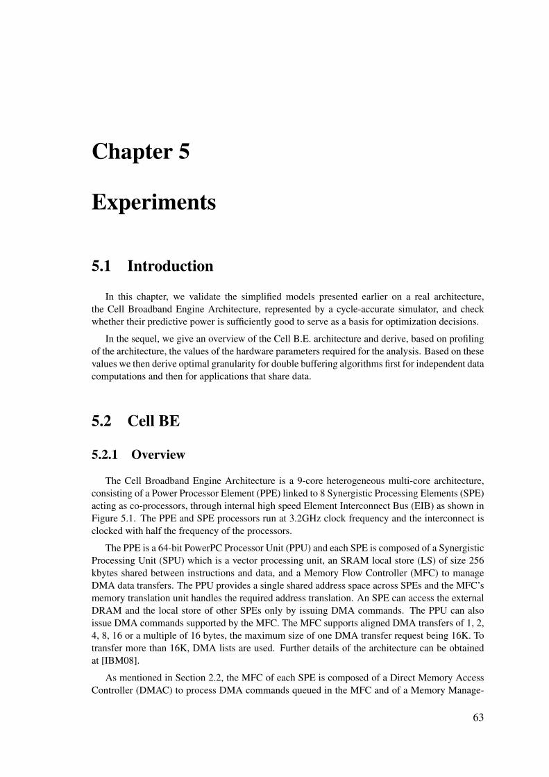
Chapter 5
Experiments
5.1 Introduction
In this chapter, we validate the simplified models presented earlier on a real architecture,the Cell Broadband Engine Architecture, represented by a cycle-accurate simulator, and checkwhether their predictive power is sufficiently good to serve as a basis for optimization decisions.
In the sequel, we give an overview of the Cell B.E. architecture and derive, based on profilingof the architecture, the values of the hardware parameters required for the analysis. Based on thesevalues we then derive optimal granularity for double buffering algorithms first for independent datacomputations and then for applications that share data.
5.2 Cell BE
5.2.1 Overview
The Cell Broadband Engine Architecture is a 9-core heterogeneous multi-core architecture,consisting of a Power Processor Element (PPE) linked to 8 Synergistic Processing Elements (SPE)acting as co-processors, through internal high speed Element Interconnect Bus (EIB) as shown inFigure 5.1. The PPE and SPE processors run at 3.2GHz clock frequency and the interconnect isclocked with half the frequency of the processors.
The PPE is a 64-bit PowerPC Processor Unit (PPU) and each SPE is composed of a SynergisticProcessing Unit (SPU) which is a vector processing unit, an SRAM local store (LS) of size 256kbytes shared between instructions and data, and a Memory Flow Controller (MFC) to manageDMA data transfers. The PPU provides a single shared address space across SPEs and the MFC’smemory translation unit handles the required address translation. An SPE can access the externalDRAM and the local store of other SPEs only by issuing DMA commands. The PPU can alsoissue DMA commands supported by the MFC. The MFC supports aligned DMA transfers of 1, 2,4, 8, 16 or a multiple of 16 bytes, the maximum size of one DMA transfer request being 16K. Totransfer more than 16K, DMA lists are used. Further details of the architecture can be obtainedat [IBM08].
As mentioned in Section 2.2, the MFC of each SPE is composed of a Direct Memory AccessController (DMAC) to process DMA commands queued in the MFC and of a Memory Manage-
63

CHAPTER 5. EXPERIMENTS
SPU
MMUMFC
SPU
MMUMFC
SPU
MMUMFC
SPU
MMUMFC
SPU
MMUMFC
SPU
MMUMFC
SPU
MMUMFC
SPU
MMUMFC
PPU
MMU
L2
XDR DRAM
Interface
I/O
Interface
Interface
Coherent
EIB
Figure 5.1: Cell B.E. Architecture
ment Unit (MMU) to handle the address translation required by the selected DMA command. TheMMU has a translation look-aside buffer (TLB) for caching recently translated addresses. TLBmisses can affect significantly the performance, therefore we neglect this effect by doing a warm-up run which will load the TLB entries before profiling of the program. Also, we allocate largepage tables to have a smaller number of TLB entries for data array. As explained previously, afterthe address translation, the DMAC splits the DMA command into smaller bus transfers. Peakperformance is achievable when both the source and destination address are 128-byte aligned andthe block size is multiple of 128 bytes [KPP06]. We can observe reduction in performance whenthis is not the case.
For our experiments, we use a Cell B.E. simulator [IBM09] whose performance are very closeto the actual processor. However, it does not model precisely all the main memory details. In theCell B.E. references, it is mentioned that it models a DDR2 memory instead of RAMBUS XDR,used in the real processor, and it does not have Replacement Management table for cache. Thisdoes not affect much the validity of our results since we do not consider either a detail descriptionof the main memory and performance is measured directly on the SPUs.
For programming the Cell B.E. platform, we use a low level library provided by the Cell B.E.SDK [IBM08]. This library gives us direct control over the platform and excludes any overheaddue to the implementation of high level constructs used by a high level programming model.However, the low level library exposes to the programmer all the low level hardware details whichrequires the programmer to have a good understanding of the architecture and its hardware con-straints, to provide an efficient implementation. One example of such hardware constraints is dataalignment issues.
In the following, using profiling we retrieve the values of the hardware parameters of the CellB.E. platform required for the analysis.
5.2.2 Hardware Parameters Measurement
To measure the DMA latency, we implement small benchmarks issuing blocking DMA re-quests and we measure the DMA transfer time as we vary the block size and shape and increasethe number of processors issuing concurrent transfer requests.
The DMA transfer time for one-dimensional blocks and accordingly the cost per byte are plot-ted in Figure 5.2. As mentioned previously, the DMA has a large initialization overhead, themeasured initialization phase time I is about 400 cycles, which is amortized for block size largerthan 128 bytes since the DMA cost per byte is reduced significantly for this value. As we increase
64 5.2. CELL BE

CHAPTER 5. EXPERIMENTS
16 64 256 1024 4096 16384
103
104
super-block size (s · b)
Transfer
Tim
e(clock
cycles)
1 SPU2 SPU4 SPU8 SPU
(a) DMA transfer time
16 64 256 1024 4096 16384
0
10
20
30
super-block size (s · b)
Cost
Per
Byte
(clock
cycles)
1 SPU2 SPU4 SPU8 SPU
(b) DMA Read Cost per Byte
Figure 5.2: DMA performance for contiguous blocks
αp
p min max avg1 1.13 14.00 2.572 1.78 29.98 4.134 3.97 47.23 11.078 5.43 87.86 18.82
Table 5.1: The transfer time per byte for two-dimensional data transfers, as a function ofthe number of processes.
the number of processors and synchronize concurrent DMA transfers, we can observe that thetransfer time is not highly affected for a small granularity because the initial phase of the transferis done in parallel in each processor’s MFC, whereas for a large granularity the transfer time in-creases proportionately to the number of processors due to the contentions of concurrent requestson the bus and bottleneck at the Memory Interface Controller (MIC) as explained in [KPP06]. Themeasured DMA transfer cost per byte to read from main memory α(1) is about 0.22 cycles perbyte, it increases proportionately to the number of processors to reach p·α(1) (for large granularitytransfers).
For two-dimensional data blocks DMA transfers, implemented using DMA lists, we also derivethe DMA parameter values based on profiling information. As modeled, these values consist ofa fixed initialization cost I0 = 108 and an initialization cost per line I1 = 50 cycles whichcorresponds to the cost of the creation of each list element.
The transfer cost per byte α is subject to variations that are more visible and amplified for rect-angular data block transfers. These variations are due to several factors such as concurrent readingand writing requests of the same processor, packet-level arbitration between requests of differentprocessors as well as the effect of strided accesses in main memory. The minimal, maximal andaverage values of αp measured for two-dimensional data are shown in Tab. 5.1 and we use theaverage value in our model.
Note that due to the characteristics of the Cell B.E. not all block size and shape combinationsare possible. Indeed a DMA list can hold up to 2K transfer elements. Each element is a contiguousblock transfer with maximum size 16KBytes. Furthermore, the Cell B.E. has a strict alignment
5.2. CELL BE 65

CHAPTER 5. EXPERIMENTS
16 64 256 1024 4096 163840
0.5
1
1.5
·107
super-block size (s · b)
ExecutionTim
e(clock
cycles)
2 SPU-pred 4 SPU-pred 8 SPU-pred2 SPU-meas 4 SPU-meas 8 SPU-meas
Figure 5.3: Independent data computations
requirements on 16-byte boundary for both DMA transfers and SPU vector instructions for whichthe processor is optimized. If this is not taken care of, the DMA engine aligns the data by itselfcausing erroneous results.
5.3 Experimental Results
For our experiments, we implement a double buffering algorithm for different benchmarks,some of them are applications where computations are completely independent and others sharedata. For each benchmark, we run the experiments as we vary the block size and shape and thenumber of processors and check whether the analytical optimum is close to the measured one andthe measured performance close to the predicted one.
Our benchmarks consist of, first synthetic algorithms of (independent/shared) computationswhere f is an abstract function for which we vary the computation workload per byte ω and thesize of shared data.
We then implement a convolution algorithm that computes an output signal based on an inputsignal and an impulse response signal. These signals are encoded as one-dimensional data arraysand the size of the impulse signal determines the size of the data window required to compute oneoutput item. We vary the size of the impulse signal to vary the size of the neighboring shared data.
Our last benchmark is a mean filtering algorithm working on a bitmap image, encoded as atwo-dimensional data array. This algorithm computes the output for each pixel as the average ofthe value of its neighborhood.
5.3.1 Independent Computations
To validate our analytical results for independent computations, we use synthetic algorithmsand focus only on one-dimensional data since, as explained previously, optimizing data granularityfor independent two-dimensional data is similar to the one-dimensional case where it is aboutoptimizing the size (and not shape) of data.
66 5.3. EXPERIMENTAL RESULTS

CHAPTER 5. EXPERIMENTS
For synthetic algorithms, we fix the size b of a basic block to 16 bytes and the size n of inputdata array to 64K, the total size of the array being 1Mbytes. Also we keep the maximal number ofthreads that are spawn on SPUs equal to the number of SPU’s. This will avoid context switchingand gives more predictable results. Also there will be no question of scheduling which is anotherpart of the problem and not in the scope of this thesis. The memory capacity limits then the pos-sible number of blocks clustered in one transfer to s̄ < 4K, excluding memory space allocatedto code size. We vary the number of blocks s and the number of processors. We compare bothpredicted and measured optimal granularity, and the total execution time for both transfer andcomputation regimes. Figure 5.3 shows the predicted and measured values for 2, 4 and 8 proces-sors. We can observe that the values are very close to each other. The predicted optimal pointsare not exactly the measured ones but they give very good performance. Performance predictionin the computation regime is better than in the transfer regime, because the computations whichconstitute the dominant part of the total execution time is performed on processors. Besides, asmentioned in [SBKD06] we have sufficient time to hide delays caused due to the network latencyand bandwidth.
5.3.2 Shared Computations
5.3.2.1 Synthetic Benchmarks
We implement the different strategies for transferring shared data explained in Section 4.2. Werun experiments with different values of k, s and p, for both computation and transfer regimes byvarying the computation workload ω. We present the results for a small and a large value of k,128bytes and 1K respectively, and for 2 and 8 processors.
In Inter-Processor Communication (IPC) strategy, we make sure that neighboring processorsexchanging data are physically mapped close to each other. Specifying affinity during threadcreation in linux allows the logical threads to be mapped physically next to each other. This givesadvantage of having higher bandwidth as mentioned in [SNBS09]. The global data partitioningspecified in section 4.2.2 has a ring geometry of communication similar to the EIB topology, sothat each processor can send data to its right neighbor. The processors must synchronize with eachother to send shared data after the DMA request for fetching a super-block from main memory hascompleted. We experiment with two variants of IPC synchronization: a point to point signalingmechanism to check the availability of shared data and acknowledge the neighbor, and a globalbarrier based on signals mentioned in [BZZL08] to synchronize all processors. Because of thehigh synchronization overhead compared to point to point signaling, we do not present here theresults obtained with this variant. After processors synchronization, the transfer of shared data isdone by issuing a DMA command.
As discussed in section 4.2.4, in the computation regime replication performs always betterthan local buffering and IPC as shown in Figures 5.4a and 5.4b. Besides, we can see that IPCperforms worse than local buffering because the cost per byte γ via load/store operations whichis around 2 cycles per byte, is much lower than the cost Rk to perform IPC synchronization andDMA calls. Rk involves a DMA inter-processor cost per byte β and a synchronization cost. Inpractice, it is very difficult to estimate Rk precisely, mainly because of the difficulty in predictingthe exact arrival time in the presence of continuous read/write data-transfers. In our experiments,the initial time of an inter-processor DMA command was around 200 cycles, the transfer cost perbyte β around 0.13 cycles and the synchronization cost between 200 and 500 cycles as we varythe number of processors. The synchronization cost using barrier is much larger, between 800 and2400 for each iteration.
5.3. EXPERIMENTAL RESULTS 67

CHAPTER 5. EXPERIMENTS
128 256 512 1024 2048 4096 8192
106
106.5
super-block size (s · b)
ExecutionTim
e(clock
cycles)
2 repl 2 ipc 2 local buffering8 repl 8 ipc 8 local buffering
(a) shared data size 128 bytes
1024 2048 4096 8192
106
106.2
106.4
106.6
super-block size (s · b)
ExecutionTim
e(clock
cycles)
2 repl 2 ipc 2 local buffering
8 repl 8 ipc 8 local buffering
(b) shared data size 1024 bytes
Figure 5.4: Overlapped data in computation regime
In the transfer regime, performance varies according to the value of k and the number of pro-cessors. We can observe in Figure 5.5a that the costs of local buffering and replication are nearlythe same, and that replication performs even better for a transfer of block size between 512bytesand 2K. This demonstrates that using DMA for transferring additional data can perform sometimesbetter than local buffering even for a small value of k, and that keeping shared data in the localstore may have a non-negligible cost. Therefore, even when considering contiguous partitioningof data, redundant fetching of shared data using replication strategy can be as efficient, if not moreefficient than keeping shared data in the local store. However, the cost of transferring shared datausing replication becomes higher than other strategies when the number of processors increasesbecause of the contentions even for small values of k.
In the following, we detail the results for each strategy in terms of efficiency and conformancewith the prediction of the models.
– Replication: For computation regime, the measured results are very close to the predictedones. The only source of error would be the contentions on the network with huge networktraffic which causes differences in the arrival time of the data. The error between the mea-sured and predicted values is about 3%. In the transfer regime, replication always performsworse than other strategies for 8 processors due to contentions.
– IPC: When synchronization is done using messages between neighboring processors, weobserve variabilities in the arrival time of data transfers and exchanged messages due tocontentions in the network. This effect increases in the transfer regime which makes the gapbetween the measured and estimated performance larger, with an error of about 6%, thatgoes to 30% when barriers are used with a high number of processors.
– Local buffering: In the computation regime, local buffering outperforms IPC for most of thecases, whereas in the transfer regime, the DMA engine can be more efficient for transferringshared data than copying it from one buffer to another in the local store, despite the inter-processor synchronization overhead.
Note that for a given k, as super-block size increases the cost of transferring shared data relativeto the overall execution time decreases and all strategies give similar performance results. In thetransfer regime, the gap between estimated and measured performance becomes larger as it is moredependent upon contentions in the network traffic for which our modeling is less accurate. There
68 5.3. EXPERIMENTAL RESULTS

CHAPTER 5. EXPERIMENTS
128 256 512 1024 2048 4096 8192
105.8
106
106.2
106.4
106.6
super-block size (s · b)
ExecutionTim
e(clock
cycles)
2 repl 2 ipc 2 local buffering
8 repl 8 ipc 8 local buffering
(a) shared data size 128 bytes
1024 2048 4096 8192
105.8
106
106.2
super-block size (s · b)
ExecutionTim
e(clock
cycles)
2 repl 2 ipc 2 local buffering
8 repl 8 ipc 8 local buffering
(b) shared data size 1024 bytes
Figure 5.5: Overlapped data in transfer regime
are two major sources of contentions that we currently do not model:
1. In the 3 stage software pipeline there is an overlap between reading super-block i and writ-ing super-block i− 1. This is the main reason why the estimated optimal granularity pointis in reality still in the transfer regime.
2. Inter-processor synchronization, in which messages exchanged between processors addcontention to the network. This overhead increases with the number of processors evenfor the more efficient inter-processor signaling variant. The exact arrival time of each mes-sage is difficult to model due to continuous read/write network traffic and the schedulingpolicy of the DMA controller.
In the following, we apply the double buffering granularity optimization on a real applicationworking on one-dimensional data: the convolution.
5.3.2.2 Convolution Algorithm
Convolution is one of the basic algorithm is signal processing [Nus81]. Assuming an inputsignal array X of a large size n and an impulse system response signal array B of a smaller sizem (m << n), the output system signal array Y of the same size n is computed as follows;
Y [i] =
m∑j=0
X[i− j] ·B[j]
Therefore to compute each sample Y [i] of the output signal, a window of m data samples isrequired from input array X . When multiple processors are used, input array is partitioned intocontiguous chunks, see Figure 5.6. The area in grey illustrates shared data between processors.
In our experiments, the size of input array X is chosen to be 1Mbytes of data, so it cannot fit inthe scratchpad memory, whereas B is small enough to be permanently stored in each SPU’s localstore. Hence double buffering is implemented to transfer data blocks of array X (resp. Y ). As for
5.3. EXPERIMENTAL RESULTS 69

CHAPTER 5. EXPERIMENTS
P2P1
X
B
Y
Figure 5.6: Convolution Algorithm.
the synthetic examples, we compare the different strategies of section 4.2 and we vary the size ofB to vary the size of shared data.
Signal samples are encoded as double data types. The minimal granularity size b is chosento be the size of the data window required to compute one output data sample, that is b = m · 8(8 being the size of a double data type). In the implementation of the algorithm, we use SIMDoperations to optimize the code. The measured cost per byte ω is about 53 cycles.
Note that for this algorithm, despite an optimized implementation using vector operations thecomputation cost per byte ω is much higher than the transfer cost per byte with maximum con-tentions α(8) (being 7.22 cycles), resulting from the use of the maximal number of available cores.Therefore, the overall execution is always in a computation regime for all strategies.
The reason why the cost per byte for this algorithm is so high is the use of double data typesto encode signals samples which does not fully take advantage of the 16 bytes SIMD enginesince operations on at most 2 elements of the array can be done in parallel. Floating point datatypes would take more advantage of the SIMD operations, however at the cost of results accuracysince the Cell B.E. does not support a floating point unit. Besides since SPU’s general registersare SIMD registers, this makes operations on the SPU not optimized for scalar operations andbranching instructions, resulting in a high execution latency.
Figure 5.7 summarizes performance results for size of B = 256 bytes, that is, 32 samples,using 2 and 8 processors. As explained in section 4.2.4, in the computation regime the replicationstrategy outperforms local buffering and IPC strategies since it avoids the computational overheadat each iteration of copying shared data locally or exchanging data between neighboring proces-sors using synchronous DMA calls. This overhead is proportional to the number of iterations andtherefore decreases with higher granularities to be eventually negligible which leads all strate-gies to perform with nearly the same efficiency. Moreover, note that in the program execution
256 512 1024 2048 4096 8192
4
4.02
4.04
4.06
super-block size (s · b)
Norm
alizedExecutionTim
e
2 repl2 ipc2 local
256 512 1024 2048 4096 8192
1
1.01
1.02
1.03
1.04
super-block size (s · b)
Norm
alizedExecutionTim
e
8 repl8 ipc8 local
Figure 5.7: Convolution using double buffering, shared data size is 256 bytes
70 5.3. EXPERIMENTAL RESULTS

CHAPTER 5. EXPERIMENTS
8 16 32 64 128
256
1
1.2
1.4
·105
Block Height s1, s2 = 4096/s1
DM
ATr
ansf
ertim
e
Super block with replicated data transfer time
Figure 5.8: Influence of block shape and its replicated data on the transfer time.
time estimation, we ignored so far the overhead at each iteration of setup variables which is alsoproportional to the number of iterations and is hence reduced for high granularity.
5.3.2.3 Mean Filtering Algorithm
We implemented a mean filter algorithm that works on a bitmap image of 512 × 512 pixels.Each pixel is characterized by its intensity ranging over 0..255. The output for a pixel is theaverage of the value of its neighborhood defined as a square (mask) centered around it whichcorresponds to the neighborhood pattern we considered.
We have experimented with different mask sizes and focus on the presentation of the resultsfor a 9 × 9 mask, that is, k = 8. In order to us SIMD operations to optimize the implementationof the code, we encode a pixel as an integer (b = 4 bytes). The computation workload per basicblock is roughly ω = 62 cycles.
First we experiment with the influence of the block shape and its implied replicated area on thetransfer time discussed in Section 4.3. For this, we fix the quantity δ = s1 × s2 and profile theDMA transfer time for different feasible combinations of (s1, s2) so that s1 × s2 = δ. Figure 5.8plots the DMA transfer time of these shapes for δ = 4096. Note that given the considered masksize, a shape (s1, s2) yields a block of s1+8 lines, each line corresponding to a contiguous transferof b · (s1 + 8) bytes. As argued in section 4.3, the optimal transfer time is obtained neither forsquare (64, 64) nor the flattest possible (8, 512) super blocks and the best trade-off in this case is(s1, s2) = (32, 128).
We then evaluate the effect of the size and shape of the super blocks and the total executiontime of the pipeline for different numbers of processors. Fig. 5.9-(a) compares the predictedand measured performance for different block shapes where s1 × s2 = 1024 while Fig. 5.9-(b) does the same for s1 × s2 = 2048. As one can see, the distance between the predicted andmeasured values is rather small except for large values of s1. The major reason for the discrepancybetween the model and the reality is that C(s1, s2) has non negligible component that depends ons1 for two reasons. The first is due to the overhead at each computation iteration related to thesetting required between the outer loop and the inner loop like adjustment of the pointers for everyrow, pre-calculation of sums of borders etc. Secondly, the creation of list elements occupies theprocessor and this overhead is also added to the overall execution time.
5.3. EXPERIMENTAL RESULTS 71

CHAPTER 5. EXPERIMENTS
2 4 8 16 32 64
4
4.5
5
·106
Block Height s1
Pipe
line
Tota
lExe
cutio
ntim
e measuredpredicted
4 8 16 32 64 128
4
4.5
5
5.5
·106
Block Height s1
Pipe
line
Tota
lExe
cutio
ntim
e measuredpredicted
(a) (b)
Figure 5.9: Predicted and measured values for different combinations of s1 × s2
2 8 32 128
4
4.5
5
5.5
·106
Block Height s1
Pipe
line
Tota
lExe
cutio
ntim
e meas s1 × s2 = 4Kmeas s1 × s2 = 2Kmeas s1 × s2 = 1K
Figure 5.10: Observed optimal granularity s∗ = (4, 256) and predicted optimal granular-ity s∗ = (64, 32).
Fig. 5.10 combines the measured results for different super block sizes. The measured optimumis obtained for (4, 256) while our calculation yield (56, 33) whose nearest feasible value is (64, 32)whose measured overall performance is less than 10% above the performance for the optimum.The discrepancy can be attributed to the reasons stated above, namely the dependence of C on s1.
5.4 Conclusion
In order to validate the analysis, we implemented and run double buffering algorithms con-sidering different benchmarks, first synthetic where we vary the computation workload per basicblock and the size of shared data, in order to vary the balance between computations and transfers.We considered then real benchmarks where computations share data: a convolution algorithmworking on one-dimensional data requiring only contiguous block transfers and a mean filteringalgorithm working on two-dimensional data requiring rectangular block transfers.
72 5.4. CONCLUSION

CHAPTER 5. EXPERIMENTS
Overall the analytical results are close to the measured ones which proves that we capturedthe important features of the problem. However, some discrepancy remains mainly because of thefollowing reasons:
– Variabilities in the architecture which influence in particular the value of α and where anaverage value is clearly not enough to capture these variabilities.
– We ignored so far the overhead per line involved in the computation time of a rectangularblock. It turns out that in the Cell B.E. architecture, this overhead is significant since, i) theissue of each list element is performed by the software which adds to the processing timeand ii) the Cell B.E. processors are vector processors not optimized for scalar and branchinginstructions which makes the extra processing required for the computation of a rectangularblock not negligible.
We believe that a right choice of the parameters values along with more detailed models canfurther improve granularity and performance predictions.
5.4. CONCLUSION 73

CHAPTER 5. EXPERIMENTS
74 5.4. CONCLUSION

Conclusions and Perspectives
The critical path of this thesis was to understand the architectural context and the new chal-lenges emerging from the current trend for designing embedded multi-core systems, which are insome aspects very different from general-purpose multi-core platforms. In fact, a particular diffi-culty in the embedded multi-core domain is the cultural gap between the software and hardwarecommunities that hold different partial views of the same system and thus problems.
For such platforms, efficient use of the memory hierarchy is crucial for performance and con-stitutes one of the major new challenges. It breaks with the implicit assumption of an unlimitedmemory space available to the program and thus puts a heavy burden on the software and theprogrammer who have to manage data movement in the memory hierarchy, granularity choice,synchronization with the computations, etc.
To tackle this problem, we have targeted a relatively-easy, but important, class of applicationswith regular patterns of computation and high volume data transfers. This choice may look toorestrictive, however array processing algorithm constitute a large part of today’s embedded appli-cations and their efficient software implementation on multi-core architectures is an activity thatwill still occupy a lot of programmers in the coming future.
Under some simplifying assumptions we constructed models that capture the main features/pa-rameters of the problem, that is the logical description of the applications and the DMA specifica-tion, with a clear separation between parameters characterizing the applications and those whichare specific to the hardware platform. A crucial point of our methodology is that the hardwarecharacterization and modeling phase can, in principle, be done once for each new platform andthen be used by different applications running on it.
The analysis turned out to approximate reasonably well the behavior of implemented bench-marks on a real architecture. However, we are of course aware of the fact that each real programand each architecture will have its own particularity, more complex and richer in parameters thanthe model we have built. The work presented in this thesis is just a first step and our main concernwas to provide an abstract view of the problem towards a more systematic way for solving suchproblems than the actual pure trial and error engineering method.
There are many possible extensions for this work and a lot is still to be done, including,
– Integrate different/more complex features of data parallel applications such as different datasharing patterns, potentially involving temporal dependency and thus allowing data depen-dent execution;
– Capture variations which is necessary if we want to move a step towards more realistic re-sults. Sources of variations can be software and/or hardware. In software they appear forinstance naturally in some filtering algorithms where the degree of filtering and thus compu-tations varies according to the structures of the image. Hardware variations are, as discussedthroughout this thesis, mainly due to the contentions on the NoC and the main memory side.
75

CONCLUSIONS AND PERSPECTIVES
We think that a more detailed model of DRAM features would help improve granularity andperformance predictions and that a dynamic tuning of the granularity between subsequentiterations maybe required to adapt to the variations in the memory access latency;
– In contrast with data-parallelism, task-level parallelism usually use multithreading to hidememory latency where multiple threads run on the same core and a context switch occursat the request of data that is not available in local memory. Combining both data and taskparallelism is in practice required since different applications can run simultaneously onthe same multi-core fabric. This will change the symmetric nature of the problem and maycreate new bottlenecks. Consideration of code distribution should also be taken into account;
– Adapt our analysis to a distributed DMA architecture where data transfers can be scheduledat the super block rather than the packet level. This way, useless contentions between subtasks of the same application can be avoided;
– So far, we considered only two memory levels in the hierarchy, main memory and processorslocal memory. We can also consider a third memory level (which is in practice alreadyavailable in platforms such as P2012). More generally, the memory hierarchy can be viewedas a tree where each node features a different speed and capacity, and one (or multiple) DMA(s) engines are used to transfer data from one memory location to another;
– Finally, we think that the best way to leverage this work is to integrate it in a completecompilation flow where the programmer writes his program as a sequential data parallel loopand a double buffering algorithm source code is generated automatically with the appropriatepartitioning for the target platform, that varies as we vary the hardware;
We are currently extending our work to P2012, which is the initial motivation for this thesis.The problem as it is so far described already matches the inter-cluster view of P2012 where eachcluster has its own local memory and DMA engine. In the same cluster, the programmer canchose between two strategies of moving data, i) a “liberal” approach where each core copies dataindependently of other cores in the cluster thus issuing a different DMA request per core, datais however stored in the shared memory. ii) a “collaborative” approach where cores in the samecluster issue simultaneously one common transfer request to serve their respective computations.It will be interesting to compare both approaches as the first offers more synchronization flexibilityand the second matches the hardware view.
76 CONCLUSIONS AND PERSPECTIVES

Bibliography
[AB86] James Archibald and Jean-Loup Baer. Cache coherence protocols: evaluation us-ing a multiprocessor simulation model. ACM Trans. Comput. Syst., 4(4):273–298,September 1986.
[ADC+03] A. Artieri, V. D’Alto, R. Chesson, M. Hopkins, and M. C. Rossi. Nomadik - Openmultimedia platform for next generation mobile devices. Technical report, 2003.
[AKN95] Anant Agarwal, David Kranz, and Venkat Natarajan. Automatic partitioning of par-allel loops and data arrays for distributed shared memory multiprocessors. IEEETrans. Parallel Distributed Systems, 6:943–962, 1995.
[Amd67] Gene M. Amdahl. Validity of the single processor approach to achieving large scalecomputing capabilities. In Proceedings of the April 18-20, 1967, spring joint com-puter conference, AFIPS ’67 (Spring), pages 483–485, New York, NY, USA, 1967.ACM.
[AP01] Turgay Altilar and Yakup Paker. Minimum overhead data partitioning algorithms forparallel video processing. In Proceedings Domain Decomposition Methods Confer-ence, pages 25125–8, 2001.
[BM02] Luca Benini and Giovanni De Micheli. Networks on chips: A new soc paradigm.Computer, 35:70–78, 2002.
[BSL+02] Rajeshwari Banakar, Stefan Steinke, Bo-Sik Lee, M. Balakrishnan, and Peter Mar-wedel. Scratchpad memory: design alternative for cache on-chip memory in embed-ded systems. In Proceedings of the tenth international symposium on Hardware/-software codesign, CODES ’02, pages 73–78, New York, NY, USA, 2002. ACM.
[BZZL08] Shuwei Bai, Qingguo Zhou, Rui Zhou, and Lian Li. Barrier synchronization for cellmulti-processor architecture. In Ubi-Media Computing, 2008 First IEEE Interna-tional Conference on, pages 155 –158, august 2008.
[CB94] T.-F. Chen and J.-L. Baer. A performance study of software and hardware dataprefetching schemes. SIGARCH Comput. Archit. News, 22:223–232, April 1994.
[CKP91] David Callahan, Ken Kennedy, and Allan Porterfield. Software prefetching. In Pro-ceedings of the fourth international conference on Architectural support for pro-gramming languages and operating systems, ASPLOS-IV, pages 40–52, New York,NY, USA, 1991. ACM.
[CMLS11] Scott Cotton, Oded Maler, Julien Legriel, and Selma Saidi. Multi-criteria optimiza-tion for mapping programs to multi-processors. In SIES, pages 9–17, 2011.
[DDS95] Fredrik Dahlgren, Michel Dubois, and Per Stenström. Sequential hardware prefetch-ing in shared-memory multiprocessors. IEEE Trans. Parallel Distrib. Syst., 6:733–746, July 1995.
[DRV00] Alain Darte, Yves Robert, and Frederic Vivien. Scheduling and Automatic Paral-lelization. Birkhauser Boston, 1st edition, 2000.
77

BIBLIOGRAPHY
[Ehr00] M. Ehrgott. Multicriteria optimization. Lecture Notes in Economics and Mathemat-ical Systems. Springer-Verlag, 2000.
[fClB95] Tien fu Chen and Jean loup Baer. Effective hardware-based data prefetching forhigh-performance processors. IEEE Transactions on Computers, 44:609–623, 1995.
[FHK+06] K. Fatahalian, D.R. Horn, T.J. Knight, L. Leem, M. Houston, J.Y. Park, M. Erez,M. Ren, A. Aiken, W.J. Dally, et al. Sequoia: Programming the memory hierarchy.In Proceedings of the 2006 ACM/IEEE Conference on Supercomputing, pages 83–es.ACM, 2006.
[Fri02] J. Fritts. Multi-level memory prefetching for media and stream processing. In Mul-timedia and Expo, 2002. ICME ’02. Proceedings. 2002 IEEE International Confer-ence on, volume 2, pages 101–104 vol.2, 2002.
[Gro08] Khronos OpenCL Working Group. The OpenCL Specification, version 1.0.29, 8December 2008.
[Gsc07] M. Gschwind. The cell broadband engine: exploiting multiple levels of parallelismin a chip multiprocessor. International Journal of Parallel Programming, 35(3):233–262, 2007.
[HP06] John L. Hennessy and David A. Patterson. Computer Architecture, Fourth Edition:A Quantitative Approach. Morgan Kaufmann Publishers Inc., San Francisco, CA,USA, 2006.
[IBM08] IBM. Cell SDK 3.1. https://www.ibm.com/developerworks/power/cell/, 2008.
[IBM09] IBM. Cell Simulator. http://www.alphaworks.ibm.com/tech/cellsystemsim, June 2009.
[IM02] Anoop Iyer and Diana Marculescu. Power and performance evaluation of globallyasynchronous locally synchronous processors. Computer Architecture, InternationalSymposium on, 0:0158, 2002.
[kLH95] Chi kin Lee and Mounir Hamdi. Parallel image processing applications on a networkof workstations. Parallel Computing, 21(1):137 – 160, 1995.
[KPP06] M. Kistler, M. Perrone, and F. Petrini. Cell multiprocessor communication network:Built for speed. Micro, IEEE, 26(3):10 –23, may-june 2006.
[KYM+07] Timothy J. Knight, Ji Young, Park Manman, Ren Mike Houston, Mattan Erez,Kayvon Fatahalian, Alex Aiken, William J. Dally, and Pat Hanrahan. Compilationfor explicitly managed memory hierarchies. In In PPoPP ’07: Proceedings of the12th ACM SIGPLAN Symposium on Principles and Practice of Parallel Program-ming, pages 226–236. ACM Press, 2007.
[LCM11] Julien Legriel, Scott Cotton, and Oded Maler. On universal search strategies formulti-criteria optimization using weighted sums. In IEEE Congress on EvolutionaryComputation, pages 2351–2358, 2011.
[LGCM10] Julien Legriel, Colas Le Guernic, Scott Cotton, and Oded Maler. Approximating thepareto front of multi-criteria optimization problems. In TACAS, pages 69–83, 2010.
[LLG+90] Daniel Lenoski, James Laudon, Kourosh Gharachorloo, Anoop Gupta, and JohnHennessy. The directory-based cache coherence protocol for the dash multiproces-sor. SIGARCH Comput. Archit. News, 18(3a):148–159, May 1990.
[LM87] E. A. Lee and D. G. Messerschmitt. Synchronous data flow. Proceedings of theIEEE, 75(9):1235–1245, 1987.
78 BIBLIOGRAPHY

BIBLIOGRAPHY
[LPB06] Mirko Loghi, Massimo Poncino, and Luca Benini. Cache coherence tradeoffs inshared-memory mpsocs. ACM Trans. Embed. Comput. Syst., 5:383–407, May 2006.
[MB09] Andrea Marongiu and Luca Benini. Efficient openmp support and extensions formpsocs with explicitly managed memory hierarchy. In DATE, pages 809–814, 2009.
[MBB10] Andrea Marongiu, Paolo Burgio, and Luca Benini. Evaluating openmp support costson mpsocs. In DSD, pages 191–198, 2010.
[MCT96] Kathryn S. McKinley, Steve Carr, and Chau-Wen Tseng. Improving data localitywith loop transformations. ACM Trans. Program. Lang. Syst., 18(4):424–453, July1996.
[MG91] Todd Mowry and Anoop Gupta. Tolerating latency through software-controlledprefetching in shared-memory multiprocessors. Journal of Parallel and DistributedComputing, 12:87–106, 1991.
[Nus81] Henri J. Nussbaumer. Fast Fourier transform and convolution algorithms. Springer-Verlag, Berlin ; New York :, 1981.
[OHL+08] J.D. Owens, M. Houston, D. Luebke, S. Green, J.E. Stone, and J.C. Phillips. Gpucomputing. Proceedings of the IEEE, 96(5):879 –899, may 2008.
[Ope08] OpenMP Architecture Review Board. OpenMP Application Program Interface, 3.0edition, May 2008.
[SBKD06] José Carlos Sancho, Kevin J. Barker, Darren J. Kerbyson, and Kei Davis. Quanti-fying the potential benefit of overlapping communication and computation in large-scale scientific applications. In Proceedings of the 2006 ACM/IEEE conference onSupercomputing, SC ’06, New York, NY, USA, 2006. ACM.
[SC10] STMicroelectronics and CEA. Platform 2012: a many core programmable accelera-tor for ultra efficient embedded computing in nanometer technology, 2010.
[SK08] J.C. Sancho and D.J. Kerbyson. Analysis of double buffering on two different multi-core architectures: Quad-core Opteron and the Cell-BE. In Parallel and DistributedProcessing, 2008. IPDPS 2008. IEEE International Symposium on, pages 1–12.IEEE, 2008.
[SNBS09] C.D. Sudheer, T. Nagaraju, P.K. Baruah, and Ashok Srinivasan. Optimizing assign-ment of threads to spes on the cell be processor. Parallel and Distributed ProcessingSymposium, International, 0:1–8, 2009.
[Ste90] Per Stenström. A survey of cache coherence schemes for multiprocessors. Computer,23(6):12–24, June 1990.
[SYN09] S. Schneider, J.S. Yeom, and D.S. Nikolopoulos. Programming multiprocessors withexplicitly managed memory hierarchies. Computer, 42(12):28–34, 2009.
[TKA02] William Thies, Michal Karczmarek, and Saman P. Amarasinghe. Streamit: A lan-guage for streaming applications. In Proceedings of the 11th International Confer-ence on Compiler Construction, CC ’02, pages 179–196, London, UK, UK, 2002.Springer-Verlag.
[WBM+03] Zhenlin Wang, Doug Burger, Kathryn S. McKinley, Steven K. Reinhardt, andCharles C. Weems. Guided region prefetching: a cooperative hardware/softwareapproach. SIGARCH Comput. Archit. News, 31:388–398, May 2003.
[WJM08] W. Wolf, A.A. Jerraya, and G. Martin. Multiprocessor system-on-chip (MPSoC)technology. Computer-Aided Design of Integrated Circuits and Systems, IEEE Trans-actions on, 27(10):1701–1713, 2008.
BIBLIOGRAPHY 79

BIBLIOGRAPHY
[WL91] Michael E. Wolf and Monica S. Lam. A data locality optimizing algorithm. SIG-PLAN Not., 26(6):30–44, May 1991.
[WM95] Wm. A. Wulf and Sally A. Mckee. Hitting the memory wall: Implications of theobvious. Computer Architecture News, 23:20–24, 1995.
[YRL+09] S.S.J.S. Yeom, B. Rose, J.C. Linford, A. Sandu, and D.S. Nikolopoulos. A Compar-ison of Programming Models for Multiprocessors with Explicitly Managed MemoryHierarchies. 2009.
[ZM02] Lintao Zhang and Sharad Malik. The quest for efficient boolean satisfiability solvers.In CADE, pages 295–313, 2002.
80 BIBLIOGRAPHY


MOT-CLEFS
Application Data Parallèles, Systemes Multiprocesseurs sur Puce, DMA, Mémoires Scrach-Pad.
TITLEOptimizing DMA Data Transfers for Embedded Multi-Cores
KEYWORDSData Parallelization, Multiprocessor Systems On Chip (MPSoCs), Direct Memory Access
(DMA), ScrachPad Memories.
ADRR : Adresse LaboISBN : t t t t t t t t t t t t t