optimization of the reinforcement positioning in the … reinforced concrete walls in 3d requested...
TRANSCRIPT

Abstract—The experimental tests, carried out on the
reinforced concrete walls under a horizontal, a cyclic and a seismic loading, have all shown that these RC walls have a more performing behavior when the steel bars are placed according to the direction of the principal stresses. However, these principal stresses are directly connected to an angle of inclination which is often to seek. The intent of this study; is to find the most possible adequate angle of inclination of the diagonal bars in order to improve the mechanical performance of the squat RC walls and also to evaluate the contribution of the diagonal web reinforcement comparing to the conventional web reinforcement. For that, we used a local approach by modeling reinforced concrete walls in 3D requested under a horizontal loading. The numerical model used for the modeling of the concrete is the damageable elastic-plastic model of ABAQUS which makes it possible to visualize the damage at the local level and to determine the mode of rupture. On the other hand, for the bars of steel an elastic-plastic model is used. The results of the simulation in terms of damage, stress and deformation are collected and they put forward the mechanical performance of the reinforcement following the direction of the principal stresses compared to the traditional reinforcement.
Index Terms—Numerical simulation, optimization, diagonal reinforcement, concrete damage, squat RC walls.
I. INTRODUCTION RC walls can be divided into three groups based on the
ratio of height to width. When the height to width ratio is greater than 2.0, they are called slender RC walls; when the height to width ratio is less than 1.0, they are called squat RC walls; when the height to width ratio is between 1.0 and 2.0, they are called medium slender RC walls.
For slender RC walls, the failure is mainly governed by flexure. In contrast, for squat RC walls, the failure is essentially governed by shear. For medium slender walls, the failure is governed by both flexure and shear. The stiffness characteristics and shear strength of RC walls have been investigated during the 1990s [1]-[5]. In the past 20 years, attention has been given to the seismic behavior of reinforced concrete walls. Strength, ductility characteristic and energy dissipation aspects of shear walls under earthquake have been studied [6]-[9]. Test results show that the conventional squat RC walls have less ductility and lower energy dissipation, which can be observed as “pinching effect” in the hysteretic response of RC walls.
The reason why the conventional squat RC walls do not
Manuscript received October 14, 2012; revised March 5, 2013. The authors are with the Civil Engineering Department, University of
Mouloud Mammeri, Tizi-Ouzou, Algeria (e-mail: [email protected], [email protected], [email protected]).
exhibit satisfactory ductility is that there is an angle between the orientations of steel bars and the principal direction of applied stresses on RC walls; therefore the capacity of steel bars cannot be fully utilized. Test results conducted by the University of Houston [10]-[12]. Show that the effect of the steel grid orientation plays an important role in the shear stress/shear strain relationships of reinforced concrete panels and walls. Both the energy dissipation capacity and the ductility are greater when steel bars are in the principal direction of the applied stresses.
However, due to the financial and the time reason, experiment results are not enough. Finite element method supplied a new way to study RC walls by computer, which can help the researcher to analyze and complete the experimental results and have a better understanding of it.
In order to improve the mechanical behavior of squat RC walls under lateral loading, RC walls of high performance are proposed having steel bars in the principal direction of applied stresses. This paper presents the simulation results from lateral loading test on the six (06) squat RC walls. It is found that the mechanical performance of squat RC walls can significantly be improved when steel bars are provided in the principal direction of applied stresses.
II. TEST PROGRAM The simulation which we will lead will highlight the
contribution of the diagonal web reinforcement on the squat RC walls compared to the conventional reinforcement. The six squat RC walls were tested under the same horizontal loading. The height, length and width of the designed RC walls are 1.0m, 1.25m and 0.15m respectively for six models (Fig. 1 (a)). The first model (CM: conventional model) characterized by conventional reinforcement (horizontal and vertical web reinforcement) (Fig. 1 (b)). The six others model (DM: diagonal model 30°, 35°, 40°,45°,50°) characterized by diagonal reinforcement, where the steel bars are provided in the direction of 30°,35°,40°,45°50° degrees to the horizontal (Fig. 1 (c)). The same quantity of steel bars is used in the six (06) specimens to highlight the contribution of the diagonal web reinforcement compared to the classical reinforcement.
III. FINITE ELEMENT MODEL The mesh for the concrete wall is the same in both cases
and linear solid elements (HEX8, ABAQUS elements C3D8/C3D8R, Lagrangian formulation) are used. The solid elements have a dimension of approximately 1.5 cm in all three directions in space, making the mesh of the concrete wall extremely fine. The reinforcement of the concrete wall is
Optimization of the Reinforcement Positioning in the Squat Reinforcement Concrete Walls
Ali Kezmane, Said Boukais, and Mohand Hamizi
IACSIT International Journal of Engineering and Technology, Vol. 5, No. 5, October 2013
635DOI: 10.7763/IJET.2013.V5.632

modeled with truss elements (ABAQUS elements T3D2). The truss elements are coupled with the HEX elements of
the concrete wall with the EMBEDDED ELEMENTS function of ABAQUS. With this function the nodes of beam elements are kinematically constrained to the nodes of the solid element which it is located in. This means that the displacement of the node of the beam element is an average value of the displacements of the neighbouring nodes of the solid element in which the beam element is embedded.
(a)
(b) (c)
Fig. 1. (a) Geometry, (b) Reinforcement of conventional model (CM), (c) Reinforcement of diagonal model (α varies between 30 ° and 50 ° with a
pitch of 5 °)
IV. MATERIAL MODEL FOR CONCRETE The mechanical behavior of this material is much more
complicated than that of the steel due to different response in compression and tension and non-linear stress-strain laws with hardening and softening branches. Failure criteria are also much more subtle than those of steel and its numerical implementation is rather cumbersome [13]. An elasto-plastic damage model is used to describe the nonlinear material properties of concrete [14]. It bases on the classical continuum damage theory [15]. The model was developed by Lubliner and al, Onate and al [16], [17] and elaborated by Lee and Fenves [18]. This model provides a general capability for the analysis of concrete structures under static or dynamic and cyclic or monotonic loading [13], [19].
A. Basic Equation Starting from an additive strain rate decomposition in
elastic and plastic parts.
plel εεε += (1)
The stress-strain relation is given in a matrix form by
( ) ( )plDd εεσ −−= 01 (2)
where d with 0 ≤ d < 1 is a scalar damage variable and the matrix D0 contains the initial, elastic material properties. So, isotropic reductions of stiffness D = (1 - d) D0 model cracking. Similar, effective values of stresses σ are introduced by σ = (1− d) σ A yield function F (Fig. 2) of combined (modified) Drucker-Prager and Rankine type determines states of failure or damage.
( ) ( ) ( )plcc
plpl pqFF εσσγσεβαα
εσ −−−+−−
== maxmax)~(31
1~. (3)
with:
( )Tplc
plt
pl εεε =~ (4)
( )xxx += 21 (5)
It represents a surface in the effective stress space and depends on two hardening variables εt
pl, εc pl, the hydrostatic
pressure 31IP −= and the von Mises equivalent stress ( ) 21
23Jq = . α , 3=γ [14] and β denote material parameters and a material function, respectively. They include the ratio fα of the biaxial to the uniaxial
compressive strength.
121
−−
=f
f
αα
α (6)
5.00 ≤≤ α (7)
( )( ) ( ) ( )ααεσεσβ +−−= 11pl
tt
plcc (8)
The evolution of the hardening variables is linked to the
three eigenvalues plplpl321 εεε ≥≥ in plε~ of the plastic
strain rate tensor that controls the distributions on εt pl and εc
pl. Consistently, only εt
pl, εc pl are activated in cases of uniaxial
tensile or compressive loading.
( )( )
pl
rr
εσ
σε ⎥
⎦
⎤⎢⎣
⎡−
=100
00~ (9)
( )⎪⎩
⎪⎨
⎧
=
≠= ∑∑
==
0,0
0,33
σ
σσσσ li
tli
tr (10)
Plastic flow is governed by the plastic flow potential G according to the non-associated flow rule.
( )σσλε
∂∂= Gpl (11)
where G is of modified Drucker-Prager type and formulated in the plane of the effective values of p and q.
IACSIT International Journal of Engineering and Technology, Vol. 5, No. 5, October 2013
636

( ) 22tantan qfpG cte ++−= ψαψ (12)
0,, ≥ectf αψ denote the dilation angle, the tensile concrete strength and a material parameter
eα that affects the exponential deviation of G from the linear Drucker-Prager flow potential, especially for small confining pressures.
Damage is caused by cracking or crushing under tensile or compressive loading conditions. Thus, tensile dt as well as compressive dc parts constitute the total damage d.
( )cttc dsdsd −−=− 1)1(1 (13)
( )σrst 211−= (14)
( )σrst = (15)
where the two functions st, sc add in stiffness effects arising from closing and reopening of cracks.
A complete recovery of stiffness is assumed for crack closing and a partial transference of damage dc takes place in cases of load cycles from compression to tension (factor ½). Fig. 3 illustrates the assumptions for a cyclic, uniaxial loading path from tensile to compressive loading and back to the tensile side. Unloading occurs linearly and plastic concrete strains remain for 0=σ .
Fig. 2. Yield function for concrete model.
Fig. 3. Uniaxial loading path with stiffness recovery.
B. Material Equations and Parameters
The relation between the uniaxial stress, dented by xσ and
the corresponding scalar plastic, denoted by pε , is assumed as [18].
( )[ ])2exp()exp(10p
xxp
xxxx babaf εεσ −−−+= (16)
where 0xf the initial yields stress, defined as the maximum stress without damage, ax and bx are two parameters determined so that this curve reproduces the response of the material. The softening behavior induces a significant numerical finite element, and in order to maintain objectivity vis-à-vis the size of the finite element Hillerborg method [20] was chosen. In this approach, the evolution law of the stress in steady softening depends on the size of the finite element. The dissipated energy at cracking is then kept constant when the size of the elements changes by refining the mesh. The energy density of cracking gfx is related to the energy of cracking Gfx by the following equation [18], [21].
cfxfx lGg = (17)
TABLE I: MODEL PARAMETERS
Parameters Denotation
Uniaxail loading
Values
cf (MPa) 32 Compression stress
cc ff 3.00 = (MPa), 9.6 Yield stress on compression
ct ff 06.06.00 += (MPa), 2.52 Yield stress on tensile
).(10 17.03 −−= mmNfaG cfft 0.11 crushing energy on tensile
)..(100 1−= mmNGG ftfc 11.3 crushing energy on compression
31
)(11000 cfE = 34922 Young module
0
2
00
212c
c
c
c
c
cc f
fff
ff
a −⎟⎟⎠
⎞⎜⎜⎝
⎛+−= 11.2 parameter controlling the curve
compression before the peak
)2
1(0c
fc
ccc
aGlfb += 84.36 parameter controlling the curve
compression after the peak
ta 0.5 parameter controlling the curve tensile before the peak
)2
1(0t
ft
ctt
aGlfb += 418.14 parameter controlling the curve
tensile after the peak
ν 0,18 Poisson's ratio
Multiaxail loading
ψ 32° dilation angle
fa 1.16 ratio of biaxial to uniaxial
ea 0.1 parameter of the flow potential G
C. Material Model for Steel Bars The constitutive behavior of steel is modeled using an
elastic plastic model. The parameters used to define this model are elastic modulus E, yield stress, σy, plastic stress, σu and Poisson’s ratio, υ. the values of these parameters are:
E = 210GPa, υ = 0.3, σy = 348Mpa, σu = 527Mpa.
IACSIT International Journal of Engineering and Technology, Vol. 5, No. 5, October 2013
637
V. RESULTS AND DISCUSSIONS The finite element model used in this study is capable of
predicting the experimental behavior of the specimens when these are subjected to a monotonic horizontal load compared to [6], [12], [22], [23]. Therefore, the behavior of RC squat walls are discussed in detail based on the numerical results.
A. Global Comparison of Damages It is noted that the classical model squat RC wall (CM) is
strongly damaged; whether it is at the base or overall in the web. We note a rupture by sliding shear at the bottom, Characterized by the horizontal crack at the base of the wall (Fig. 4 CM). This one is obtained by progressive plasticization of the vertical reinforcements under the action of bending and shearing. The web of the squat RC wall becomes deformed in rhombus generating a rupture by shearing action, illustrated by the cracking of the concrete in diagonal (the diagonal “red” bands. Fig. 5 CM) and by plasticization of the reinforcements along the crack. A rupture by shearing action in the concrete of the web of the conventional model (CM) is produced by the crushing of the concrete following the struts of compression (Fig. 4 CM) which transmit the efforts to the base.
CM DM30° DM35°
DM40° DM45° DM50°
Fig. 4. Representation of compressive damage in concrete
Fig. 4 and Fig. 5 show that the behavior of squat RC walls is more efficient under lateral loading, when the steel bars are placed diagonally. All lateral force in walls with conventional web reinforcement must be transferred through the concrete by compressive and tensile struts and aggregate interlock and by dowel action in the reinforcement at the base of the walls. Web crushing failures occur when the compressive stress exceeds the average compressive strength of the concrete in the strut. The diagonal web reinforcement helps transfer part of shear force directly to the foundation by tension in the web reinforcement. As a result, the shear force carried by the compressive and tensile struts is reduced.
In all five models with diagonal reinforcement, we found that the model at 50 ° (DM50 °) gives the most satisfactory result compared to other models (° DM30, DM35 , DM40°, DM40°, MD50 °), this means that 50 ° is the most efficient
angle for a direct transfer of part of the shear stress in the case of the geometric shape of the considered element.
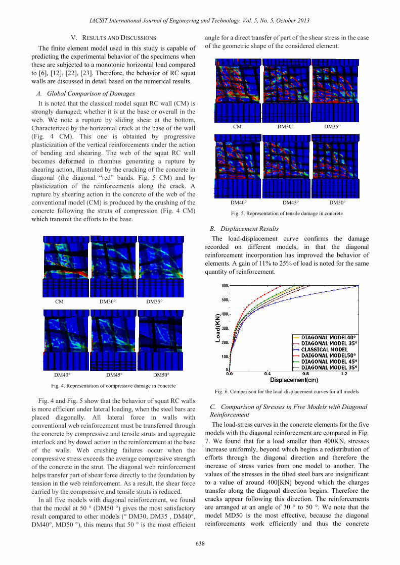
CM DM30° DM35°
DM40° DM45° DM50°
Fig. 5. Representation of tensile damage in concrete
B. Displacement Results The load-displacement curve confirms the damage
recorded on different models, in that the diagonal reinforcement incorporation has improved the behavior of elements. A gain of 11% to 25% of load is noted for the same quantity of reinforcement.
Fig. 6. Comparison for the load-displacement curves for all models
C. Comparison of Stresses in Five Models with Diagonal Reinforcement The load-stress curves in the concrete elements for the five
models with the diagonal reinforcement are compared in Fig. 7. We found that for a load smaller than 400KN, stresses increase uniformly, beyond which begins a redistribution of efforts through the diagonal direction and therefore the increase of stress varies from one model to another. The values of the stresses in the tilted steel bars are insignificant to a value of around 400[KN] beyond which the charges transfer along the diagonal direction begins. Therefore the cracks appear following this direction. The reinforcements are arranged at an angle of 30 ° to 50 °. We note that the model MD50 is the most effective, because the diagonal reinforcements work efficiently and thus the concrete
IACSIT International Journal of Engineering and Technology, Vol. 5, No. 5, October 2013
638

elements are relieved involving a reduction of stresses in concrete rods compared to other models.
The load–stress development curves for the reinforcement element of all the diagonal models specimen based on the finite element model results are compared in Fig. 8. It can be seen that stresses in steel truss are small when walls began to undergo a top horizontal load. At that moment there was no diagonal crack in web concrete and most of the loads were supported by the concrete. At the load level of about 400 KN, diagonal cracks appeared in the web concrete and stress redistribution took place between the concrete and the reinforcements, which was represented as the abrupt increase of stress in steel.
Fig. 7. Comparison of load-stress curves in concrete for diagonal models
Fig. 8. Comparison of load-stress curve in steel bars for diagonal models.
VI. CONCLUSION The finite element model of the six squat RC walls in this
study can provide a wide range of information that are useful for the study of the behavior of squat reinforced concrete walls. The Finite element model in this study has supplied a new way of studying reinforced concrete walls by computer, which will help the researcher to have a better understanding of it.
For a same quantity of reinforcement, the numerical results in this study indicate that, diagonal web reinforcement is effective in transferring the shear force to the foundation and the shear forces carried by the compressive and the tensile struts are evidently reduced comparing to the classical web reinforcement.
The comparison of the five models under a diagonal reinforcement shows that 50° is the most performing angle to transmit the shearing forces more directly to the foundation.
This implies that 50° is the nearest direction of the principal stresses developed.
It should be noted that 50° is the most performing angle, only in the case of the geometry considered in this study in which the height-width ratio equalizes to 0.8
REFERENCES [1] A. S. Elanashai, K. Pilakoutas, and N. N. Ambraseys, “Experimental
behavior of reinforced concrete walls under earthquake loading,” Earthquake Engineering and Structural Dynamics, vol. 19, no. 3, pp. 389-407, April 1990.
[2] C. R. Farra and W. E. Baker, “Measuring the stiffnes of concrete shear walls during dunamic tests,” Experimental mechanics, vol. 32, no. 2, pp. 179-183, June 1992.
[3] F. Y Cheng, G. E. Mertz, M. S. Shen, and J. F. Ger, “Computer dversus observed inelastic seismic low-rise RC shear walls,” Journal of Structural Engineering , vol. 119, no. 11, pp. 3255-32257, Nov. 1993.
[4] V. Colotti, “Shear behavior of RC walls,” Journal of Structural Engineering, vol. 119, no. 3, pp. 728-756, Mar. 1993.
[5] S. L Wood, “Shear strength of low-rise reinforced concrete walls,” ACI Structural Journal, vol. 87, no. 1, pp. 99-107, Jan-Feb. 1990.
[6] K. Pilakoutas and A. S. Elnashi, “Cyclic behavior of reinforced concrete cantilever, Part II: discussions and theoretical comparisons,” ACI Structural Journal, vol. 92, no. 4, pp. 425-434, Jul-Aug. 1995.
[7] L. Y. Mo and J. Y. Kuo “Experimental studies on low-rise structural walls,” Materials and Structures, vol. 31, no. 211, pp. 465-572, Aug-Sep. 1998.
[8] L. Y. Mo and Y. C. Lee, “Shake table tests on small-scale low-rise structural walls with various sections,” Magazine of Concrete Research, vol. 52, no. 3, pp. 177-184, June. 2000.
[9] M. S Lopes, “Experimental shear-dominated response of Rc walls. Part I: Objectives, methodology and results,” Engineering Structures, vol. 23, no. 3, pp. 229-239, Mar. 2001.
[10] M. Mansour, J. Y. Lee, and T. T. C. Hsu, “Constitutive laws of concrete and steel bars in membrane elements under cyclic loading,” Journal of Structural Engineering ASCE, vol. 127, no. 12, pp. 1502-1411, Dec. 2001.
[11] A. A Tasnimi, “Strength and deformation of mid-rise shear walls under load reversal,” Engineering Structures, vol. 22, no. 4, pp. 311-322, Apr. 2000.
[12] C. Sittipunt, S. L. Wood, P. Lukkunaparasit, and P. pattararattanakul, “Cyclic behavior of reinforced concrete structural walls with diagonal web reinforcement,” ACI Structural Journal, vol. 98, no. 4, pp. 554-562, Jul-Aug. 2001.
[13] W. Nechnech, “Contribution à l’étude numérique de comportement du béton,” Ph.D. dissertation, Dept. Civil. Eng., INSA of Lyon, 2000.
[14] Abaqus user’s manual, Dassault Systems Simulia Corp. Rising Sun mills 166 Valley street Providence, Ri 02909-2499, USA.
[15] L. M. Kachanov, Introduction to Continuum Damage Mechanical, Kluwer Academic Publisher, Dordrecht. 1990.
[16] J. Lubliner, J. Oliver, S. Oller, and E. onate, “A plastic –damage model for concrete,” International Journal of Solids and Structures, vol. 25, no. 3, pp. 299-326, 2001.
[17] S. Oller, E. Onate, J. Oliver, and J. Lubliner, “Finite element nonlinear analysis of concrete structure using a plastic-damage model,” Engineering Fracture Mechanics, vol. 35, pp. 219-231, 2001.
[18] J. Lee and G. L. Fenves, “Plastic-damage model for cyclic loading of concrete structures,” Journal of Engineering Mechanics, vol. 124, no. 8, pp. 892-900, 1998.
[19] T. Jankowiak et al., “Identification of parameters of concrete damage plasticity constitutive model,” Foundation of Civil and Environmental Engineering, 2005.
[20] A. Hillerborg, M. Modeer, and P. E. Petersson, “Analysis of crack formation and crack growth in concrete by means of fracture mechanics and finite elements,” Cement and Concrete Research, vol. 6, pp. 773-782, 1976.
[21] J. R. Rots, “Computational modeling of concrete fracture,” Ph.D. dissertation, Delft, University of Technology., Netherlands, 1988.
[22] N. Ile, “Contribution à Compréhension du fonctionnement des voiles en béton armé sous sollicitation sismique apport de l’expérimentation et de la modélisation à la conception,” Ph.D. dissertation, Dept. Civil. Eng., INSA of Lyon, 2000.
[23] T. Paulay and M. J. N. Priestley, Seismic design of reinforced concrete and masonry buildings, New York Willy and Sons, 1990.
IACSIT International Journal of Engineering and Technology, Vol. 5, No. 5, October 2013
639

Ali Kezmane was born in Tizi-Ouzou on November 14, 1988. Educational background: June, 2005 baccalaureate sciences, High school of Maatkas, Tizi-Ouzou, Algeria. June, 2008 Bachelor in Civil Engineering, University of Tizi-Ouzou, Algeria. July, 2010 academic Master in Civil Engineering, option: Structures and materials, University. After his master, he register to the Phd studies in Civil Engineering in Tizi-Ouzou University option structures and
materials,Algeria, and now he is in the second year Phd. since November 2011, he is assistant teacher in the department of architecture, responsible for practical work in the department of physical at Tizi-Ouzou University in Algeria.
Sais Boukais was born in Azazga on May 1, 1958. Educational background: June, 1979 baccalaureate science, Chihani Bachir high school, Azazga, Tizi-Ouzou (Algeria). January, 1985 Engineer degree in Civil Engineering, Polytechnic El-Harrach, Alger (Algeria). July, 1989, Master of sciences (by research), University of Dundee, Scotland, UK. He joined the University UMMTO Tizi-Ouzou upon his return in 1989, where he performs the function of
lecturer until now. Since 2006, he joined the LaMoMS Laboratory, Faculty of Engineering of the construction of the UMMTO in which he participated as a researcher in projects related to the strengthening and rehabilitation of reinforced concrete structures.
Hamizi Mohand was born in Azazga on February 11, 1959. Educational background: June, 1979 Baccalaureate mathematics, Chihani Bachir high school, Azazga, Tizi-Ouzou (Algeria). 1984, Engineer degree in Civil Engineering, Polytechnic El-Harrach, Alger (Algeria). 1985, New intensive course in English as a second language, Carlton University, Ottawa (Canada). 1987, Master of sciences
(structures), Laval University of Québec, (Canada). 2007, Doctor of Science (structures), Mouloud Mammeri University of Tizi-Ouzou (Algeria). Habilitation research, Mouloud Mammeri University of Tizi-Ouzou (Algeria). His research work mainly oriented to the vulnerability and rehabilitation of civil structures.
After the position of head of the department of civil engineering since 2010, he has just been appointed Dean of the Faculty of Engineering building (23 September 2012).
Dr. M. Hamizi has been designated in 2012, Civil Engineering Representative of Algeria for the European Union in the framework of Tuning Africa: "Joint Africa-EU Strategy seminars Tuning".
IACSIT International Journal of Engineering and Technology, Vol. 5, No. 5, October 2013
640