optimization of hpdc process using flow simulation - case studies
TRANSCRIPT
This paper is subject to revision. Statements and opinions advanced in this paper or during presentation are the author’s and are his/her responsibility, not the Association’s. The paper has been edited by NADCA for uniform styling and format. For permission to publish this paper in full or in part, contact NADCA, 241 Holbrook, Wheeling, Illinois, 60090, and the author.
Optimization of HPDC Process using Flow Simulation - Case Studies
A.Pari Director
CRP (India) Private Limited #79, SIDCO Industrial Estate, Tirumudivakkam, Chennai, INDIA 600 044.
Phone : +91 44 6538 9191 / 9192 Fax : +91 44 2478 3408 E-mail : [email protected] Home Page : www.crpindia.in
ABSTRACT This presentation will highlight some of the case studies, where the flow simulation results helped in the HPDC optimization process in terms of various approaches viz., Failure Mode Analysis, Product Design Improvements, Cause and Effect, Design Simplification, Alternate Designs, Fixing and Revision of Acceptance Criteria, New Concepts, thereby giving CRP many solutions and it’s Customers a lot of satisfaction. INTRODUCTION CRP (India) Private Limited is a leading manufacturer of High Pressure Die Casting Products in India. It was founded in the year 1975 by Mr.N.Kunchithapatham, one of the pioneers in the country, in the field of Die-Casting in terms of Design and Manufacturing of HPDC Dies as well as Production of Castings. CRP is a one stop solution provider for the HPDC Products, having expertise in the Product Design, Die Design, Die Manufacturing, Die-casting, Machining, Surface Finishing, Powder Coating, Assembly and Testing. The vast experience and the effective use of various tools such as CAD/CAM, Flow Analysis, has made CRP a pioneer in this field. CRP has joined hands with Twin City Die Castings Company of USA in September 2009 to promote a Joint Venture in India to cater to the growing needs of technical and engineered die castings. Having seamlessly integrating Flow Analysis into its Design process and completing hundreds of simulations so far, CRP has got lot of experiences and wisdom to share with the user community. This presentation will be a continuation of the paper #102 presented at 113th Metal Casting Congress at Las Vegas, and subsequently published in the July’09 copy of the NADCA’s DIE CASTING ENGINEER under the title “Optimization of HPDC Process Using Flow Simulation – Case Studies” The presentation will highlight some of the new and more interesting case studies, where the flow simulation helped in the HPDC optimization process in terms of
- Failure Mode Analysis, - Part Design Improvements - Cause and Effect - Design Simplification - Alternate Designs - Fixing and Revision of Acceptance Criteria - New Concepts
by means of Flow Simulations, Solidification Simulations and Thermal Die Cycling Simulations

CASE STUDIES The following case studies explain the various approaches towards the application of flow simulations in HPDC Process. CASE STUDY ONE: FAILURE MODE ANALYSIS The first three case studies are pertaining to a very critical part viz., Crank Case used in an automobile compressor application. During production process, the die was found to wear very frequently resulting in high rejection rate, frequent break downs resulting in interrupted production for die maintenances. The Process audit revealed a very high injection velocity of more than 2 m/sec where as the theoretical velocity needed was less than 1 m/sec. This high velocity results in a very high gate velocity, thereby causing the rapid die erosion especially near the gate area (Fig 1.1).
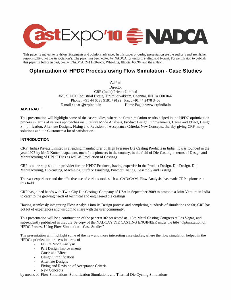
Fig. 1.1 Moving Core of the Die showing high wear near the gate area. The design of experiment revealed that the high velocity is required, without which the part was not filling properly. On the other hand the part geometry does not allow any more increase in gate area, creating a deadlock situation. The flow simulations for defect predictions were done for velocity of 0.8m/sec (Fig 1.2) and 2.2m/sec (Fig 1.3).
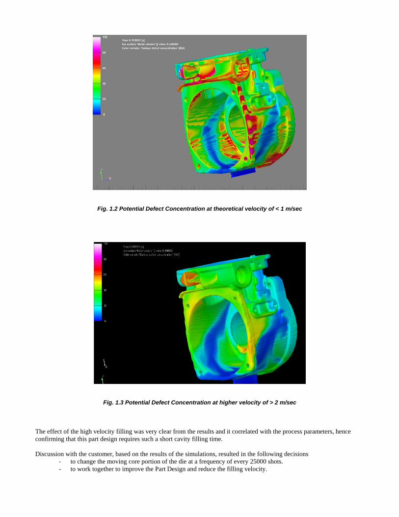
Fig. 1.2 Potential Defect Concentration at theoretical velocity of < 1 m/sec
Fig. 1.3 Potential Defect Concentration at higher velocity of > 2 m/sec
The effect of the high velocity filling was very clear from the results and it correlated with the process parameters, hence confirming that this part design requires such a short cavity filling time. Discussion with the customer, based on the results of the simulations, resulted in the following decisions
- to change the moving core portion of the die at a frequency of every 25000 shots. - to work together to improve the Part Design and reduce the filling velocity.

- to revisit the acceptance criteria without affecting the form, fit and function of the part, considering the intricacy of the part as revealed by the simulation.
CASE STUDY TWO: PART DESIGN IMPROVEMENTS This case is a continuation of the previous one, in terms of the design improvements as suggested by CRP. On a close scrutiny of the design and the part drawing, it was found that the general radius was called for as 1.6 mm, where as in the design as well as the actual part, a general radius of less than 1 mm was maintained. This has been a request from the customer to give a better aesthetics to the part and CRP was forced to accept the same. It is well known fact that the increase in the radius will contribute towards improved flow there by mitigating the flow problems. It will also enhance the strength of the part as well reduce the damages during handling and use. In other words for the designer of the part, the radius is always a bliss. Hence flow simulations were carried out in order to find out the effects of various general radii including the existing radius of 1 mm (Fig 2.1), the design specified radius of 1.6mm (Fig 2.2) and the suggested radius of 2mm (Fig 2.3).
Fig. 2.1 Potential Defect Concentration with Existing General Radius of 1.0 mm
Fig. 2.2 Potential Defect Concentration with Specified General Radius of 1.6 mm

Fig. 2.3 Potential Defect Concentration with Suggested General Radius of 2.0 mm The results helped CRP to persuade the customer to agree on the suggested general radius of 2.0 mm. This was implemented in the new die resulting in not only the plunger velocity reduction from 2.2 to 1.5 m/sec but also resulted in the reduction of process rejection from more than 25% to less than 7%. It is altogether a different story when the same customer appreciated the new design for its better aesthetics due to the improved radius (Fig 2.4). At last it was a tale of “radius conquering the sharp edge”.
Fig. 2.4 Suggestion for radius improvements at various places CASE STUDY THREE: CAUSE AND EFFECT This case is also a continuation of the previous two, in terms of cause and effect correlation and acceptance criteria. Porosity was always an issue since the beginning of the development of this part, as it is needed to be pressure tight. But the intricacy of the part and the porosity requirements coupled with the design issues discussed in the previous two cases were already causing heavy rejections. One day during the course of the above improvements, we received a SOS quality alert from the customer, claiming that there was a sudden spurt of rejection levels to more than 65% due porosity from the earlier level of about 20% in the previous batch.

The process audit found the surge of defects was attributed to a particular cored hole in the casting that too in a particular depth and in a particular direction. The die history revealed that there was a request from customer to change the cored hole from the existing 4.5 Dia to 3.5 Dia, to solve a position issue in the machining of the part. As we suspected the issue may be pertaining to shrinkage porosity in the said hole, a solidification simulation was carried out.
Fig. 3.1 Correlation of Part model (left) and simulation result (right) The simulation categorically revealed that there is a potential shrinkage porosity issue at the location (Fig 3.1) and addition of machining stock of 1 mm over the diameter is not at all recommended. Even though the customer refused to buy our idea initially, they were forced to revert back to the original core diameter of 3.5 mm on seeing the simulation results. The batch produced immediately after the core pin change had a porosity level of around 15% which clearly vindicated our stand and resolved the issue and cleared our name. This has also resulted in the customer having a more pragmatic look at acceptance levels and relaxed the acceptance criteria in terms of porosity without compromising on other requirements including the leak. And the new level of acceptance reduced the defects to less than 5%, making the part more viable and interesting to produce. To mitigate the porosity levels and flow related issues CRP has suggested more part design improvements (Fig 3.2) focusing on further radius improvements at specific areas and avoiding uneven wall thicknesses.
Fig. 3.2 Suggested Part Design Improvements
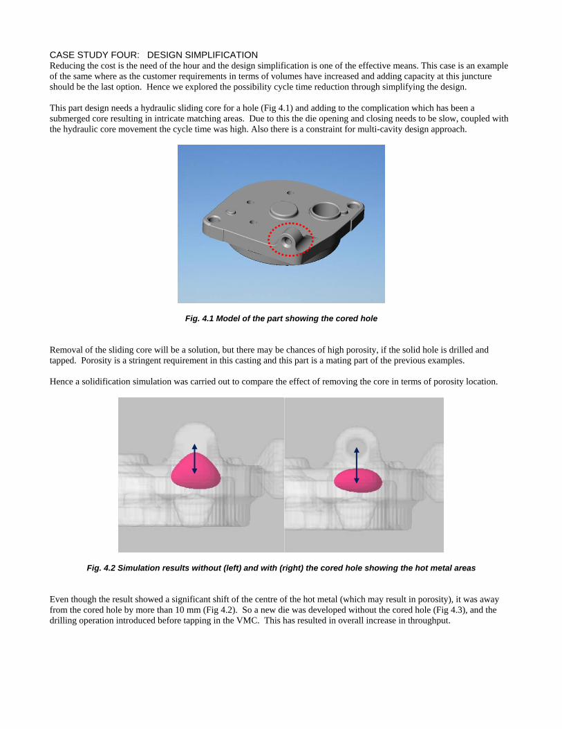
CASE STUDY FOUR: DESIGN SIMPLIFICATION Reducing the cost is the need of the hour and the design simplification is one of the effective means. This case is an example of the same where as the customer requirements in terms of volumes have increased and adding capacity at this juncture should be the last option. Hence we explored the possibility cycle time reduction through simplifying the design. This part design needs a hydraulic sliding core for a hole (Fig 4.1) and adding to the complication which has been a submerged core resulting in intricate matching areas. Due to this the die opening and closing needs to be slow, coupled with the hydraulic core movement the cycle time was high. Also there is a constraint for multi-cavity design approach.
Fig. 4.1 Model of the part showing the cored hole
Removal of the sliding core will be a solution, but there may be chances of high porosity, if the solid hole is drilled and tapped. Porosity is a stringent requirement in this casting and this part is a mating part of the previous examples. Hence a solidification simulation was carried out to compare the effect of removing the core in terms of porosity location.
Fig. 4.2 Simulation results without (left) and with (right) the cored hole showing the hot metal areas Even though the result showed a significant shift of the centre of the hot metal (which may result in porosity), it was away from the cored hole by more than 10 mm (Fig 4.2). So a new die was developed without the cored hole (Fig 4.3), and the drilling operation introduced before tapping in the VMC. This has resulted in overall increase in throughput.
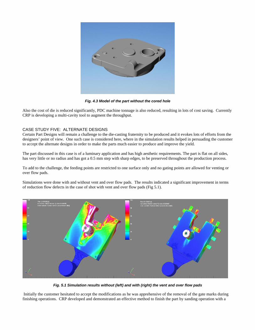
Fig. 4.3 Model of the part without the cored hole Also the cost of die is reduced significantly, PDC machine tonnage is also reduced, resulting in lots of cost saving. Currently CRP is developing a multi-cavity tool to augment the throughput. CASE STUDY FIVE: ALTERNATE DESIGNS Certain Part Designs will remain a challenge to the die-casting fraternity to be produced and it evokes lots of efforts from the designers’ point of view. One such case is considered here, where in the simulation results helped in persuading the customer to accept the alternate designs in order to make the parts much easier to produce and improve the yield. The part discussed in this case is of a luminary application and has high aesthetic requirements. The part is flat on all sides, has very little or no radius and has got a 0.5 mm step with sharp edges, to be preserved throughout the production process. To add to the challenge, the feeding points are restricted to one surface only and no gating points are allowed for venting or over flow pads. Simulations were done with and without vent and over flow pads. The results indicated a significant improvement in terms of reduction flow defects in the case of shot with vent and over flow pads (Fig 5.1).
Fig. 5.1 Simulation results without (left) and with (right) the vent and over flow pads
Initially the customer hesitated to accept the modifications as he was apprehensive of the removal of the gate marks during finishing operations. CRP developed and demonstrated an effective method to finish the part by sanding operation with a

fixture, resulting in the customer accepting the proposed design. Now CRP can substantially reduce the reject levels from the existing level of more than 40 percent, if not eliminating it. CASE STUDY SIX: FIXING AND REVISION OF ACCEPANCE CRITERIA It is always desirable to fix acceptance criteria for porosity, upfront at the beginning of a product life cycle. But most of the time it is difficult to implement, as it is not easy to estimate and fix the extent and locations of the defects. Here is one such case where in the simulation results in correlation with the actual defects, used to fix the acceptance criteria with the customer. The part is a thermostat housing of an automobile application. Once the bulk production started, the porosity levels were found very high, especially in two areas. First is the area were a 3mm depth groove is machined on an internal diameter surface. Second is the area where an angular solid boss is machined by drilling and tapping. The 3mm groove area porosity was due to flow defect concentrations as revealed b the flow simulations (Fig 6.1). It was also easy for the customer to see that this porosity will not affect the product requirement at it is only a recess for a circlip.
Fig. 6.1 Flow Simulation results showing defects concentration in the Groove machining area The angular solid boss area porosity was due to shrinkage as revealed by the solidification simulation ( Fig 6.2). It was also clear that this porosity will not result in any leakage or breakage.

Fig. 6.2 Solidification Simulation results showing hot metal at the angular solid boss area In both the areas, the correlation of the results and the actual defects were spot on. Part Design and die design options are ruled out and hence mutual acceptance levels has been arrived at and agreed upon with the customer. CASE STUDY SEVEN: NEW CONCEPTS Everything around us changes rapidly and out of the box thinking is the order of the day. Lateral thinking by the designers will evoke simple solutions even for complex problems. This case is a typical example. Using a chill is a common concept to avoid / shift porosity in gravity casting. One of the automotive application part viz., oil filter adaptor, which has porosity and leak proof requirements was ever a challenge and CRP thought of implementing this “chill” idea. One of the critical bore areas of this part had the issue of last fill as well as shrinkage porosity issues. The core pin at this location was very small and cooling systems for it will be complex and costly. Hence it was decided to use a copper chill inside the core pin to rapidly take away the heat from the tip if the pin through the centre portion (Fig 7.1).

Fig. 7.1 Model showing the concept of copper chill within the core pin
The condition was simulated with the emerging technique called thermal die cycling simulation and the results were encouraging (Fig 7.2).
Fig. 7.2 Thermal Die Cycling Simulation results without (left) and with (right) the copper chill The chill was implemented and the actual measured temperature profiles of the core pin without and with chill were found within 20C of the simulation results and correlation was amazing. The porosity levels were significantly reduced from, above 20% to less than 5%. The key aspect in this design is to ensure proper contact of copper with the die material on all sides and at all the times and this was ensured in the manufacturing in order to achieve this remarkable result.

CONCLUSSION The rapidly changing world throws up lots of challenges and die-casting field is no exception. Product life cycles are getting shorter and times are shrinking. But technologies and tools are emerging to face these challenges. It is up to us to find, learn, apply and master them in order to be successful and peaceful. CRP was able to apply the innovative use of technology coupled with effective application of experience to achieve efficient, swift and successful results. The author hopes to rekindle a few thoughts, buy sharing these case studies in order to stimulate the use of simulations and encourage other die-casters to seriously try it by themselves. Let us pledge to save the earth for the future generations to come, by not contributing to waste and by contributing to the elimination of the waste, no matter what will be its form, shape or size, and by whatever it takes. Flow Simulations are definitely one of the effective means as far as Die-castings are concerned in terms of eliminating and pre-empting the wastages. ACKNOWLEDGMENTS The author would like to thank the following, All my colleagues at CRP for the help and support, especially Mr.M.V.Parithi, Mr.M.Sukumar, Mr.R.Viswanathan, Mr.M.Paramasivam, Mr.V.Chinnapaiyan, Mr.C.Kumar. For all the encouragement and support Mr.B.Ravindran and Mr.K.Sendil Kumar - Kaushiks International, Bangalore, India. Mr. Matti Sirviö - Conifercast, Finland Mr. Thomas Jenson - Flow Science, USA.