optimization of bag forming machine c20
TRANSCRIPT

INTERNSHIP REPORT OPTIMIZATION OF BAG FORMING MACHINE C20
Safepak (Pty) Ltd
Cape Town, South Africa
Supervisor: Grant Thorburn
University of Twente
Enschede, The Netherlands
Academic supervisor: Prof. dr. ir. A. de Boer
Tom Eller (s0169625)
Applied mechanics, CTW
29-08-2011 to 30-11-2011

1
INTERNSHIP REPORT OPTIMIZATION OF BAG FORMING MACHINE C20
Tom Eller (s0169625)
Applied mechanics, CTW
29-08-2011 to 30-11-2011
Safepak (Pty) Ltd
16 Old Mill Road
N’dabeni, 7405
Cape Town
South Africa
Supervisor:
Grant Thorburn
University of Twente
PO Box 217
7500 AE Enschede
The Netherlands
Academic supervisor:
Prof. dr. ir. A. de Boer

2
1 PREFACE AND ACKNOWLEDGEMENT
From the 29th of August until the 30th of November 2011 I did an Internship at the South African
packaging company Safepak (Pty) Ltd. Safepak is situated in Cape Town and serves a variety of
industries throughout South Africa as a manufacturer of high quality flexible packaging products. The
internship is part of my 2 year master programme which I conduct at the University of Twente in The
Netherlands. The master programme consists of a year of courses specialized on applied mechanics,
a three month internship and 9 months graduation.
The factory manager of Safepak, Grant Thorburn, set me up with a project to improve the
performance and dramatically decrease waste rates on one of the bag forming machines in the plant.
This machine used to make bags for all different kinds of customers, but will be redesigned and
optimized for making diaper bags with strip handles. Grant exposed me to all kinds of stand-alone
side projects to get me acquainted with the various technical subjects involved in bag making.
Together with my main project, the redesign of machine C20, I gained a lot of practical experience.
Mechanical design, motor, gearbox and bearing selection, making technical drawings, getting
feedback from the workshop and training machine operators were all part of the assignment. Not
less important is the experience of working in a business environment, communicating with
managers and other staff, both within and outside the company. In the last week at Safepak I had the
opportunity to present my achievements to the management board, convincing them not only of the
benefits for Safepak, but also of the benefits for all other Dutch students to come.
To conclude, the internship at Safepak offered me a personal experience and a personal
development at the same time. I developed new skills, especially on practical engineering matters,
became more independent and gained professional experience. By learning and understanding a
different culture, I now have a broader perspective of the world which is a personal gain of this
internship. During this process, Grant gave me extensive guidance sharing his knowledge and
experience. Not only was he always ready to help me with my assignments at Safepak, also outside
working hours he showed personal interest and invited me for various leisure activities in and around
Cape Town. For that, I would like to express my gratitude to him. I would also like to thank Greg
Sayers for his practical advice and feedback from the workshop, Aard Duivenvoorden for setting up
my first contacts with Safepak and Tony Aspeling for arranging my accommodation in Cape Town.

3
2 MANAGEMENT SUMMARY
This report covers the main design decisions made during the re-engineering of bag forming machine
C20. Machine C20 is situated in the conversion department of the plant and has several operational
shortfalls, causing long downtimes and high waste rates.
First, the current setup of machine C20 was analysed with specific reference to these operational
shortfalls. It was found that a difference in tension between the main film and the strip films was
causing problems in the final product. Furthermore, the machine produces bad seals when it is
stopped and restarted by machine operators. These operators didn’t seem to work very structured
either: they hardly ever notice a reel running out and don’t have a systematic set up plan to do job
changeovers on C20. Finally, there were several alignment problems to be solved.
The re-engineering of machine C20 can be split up in four different parts: the unwind system for the
main reel, the unwind system for the strip reels, the folding frame and some smaller, remaining
projects. For the unwind system of the main reel, a tensioning system, a line guide and safety chucks
were implemented. The tensioning system consists of a pneumatic system with a dancer roller and
brakes and makes sure that the tension in the film remains constant. The line guide controls the
horizontal position of the film in the machine, tracking a printed line and actuating the position of the
main reel. The safety chucks enable machine operators to quickly change the reel. The advantage of
a safety chuck is that the driving mechanism of the shaft does not need to be removed when the
core holding shaft is exchanged. Total costs for this subsystem are estimated at R 70.500, in which
workshop hours and materials are the biggest expense.
For the unwind system of the strip reels, a braking mechanism was selected with total costs as main
criterion. An AC motor with variable speed drive was selected to deliver the braking moment, an arm
with a rotational potentiometer measures the current reel diameter and gives the necessary
feedback. With this system, the tension is controlled at the same tension as the main film. The strip
unwinds will be mounted on the sides of the unwind station, under a angle with the main reel.
To guide the strip films to the correct location on the main film, an adjustable ‘fold-in’-mechanism
will be incorporated in the frame. Total costs for this subsystem are estimated at R 62.800, again
with workshop hours and materials as the biggest expense.
The folding frame was redesigned to incorporate the gusset folder. In the old situation, the folding
mechanism consisted of two separate stations: at the first station, the plastic film was folded in half
using a so-called A-frame folder, the second station created a gusset into the folded side of the film.
Disadvantage of having two separate stations is the difficult alignment procedure when setting up
the machine. The new design incorporates both folders into one frame and has a spring loaded
mechanism to avoid tearing the film. Total manufacturing costs are estimated at R 25.000.
Finally, the flying knife attachment was reconsidered to enhance operator friendliness and bigger
pneumatic pistons were selected for the nip rollers. A systematic set up procedure was developed to
reduce waste during product changeovers. During machine set up, operators wasted hundreds of
meters of high quality, printed plastic film. After the first test with the new set up plan, only 3 meters
of material was wasted, which is a promising result.
The total re-engineering costs are estimated at R 162.200.

4
3 CONTENTS
1 Preface and acknowledgement ........................................................................................................ 2
2 Management summary..................................................................................................................... 3
3 Contents ............................................................................................................................................ 4
4 Introduction ...................................................................................................................................... 5
5 Evaluation of the current bag forming station ................................................................................. 6
5.1 Current setup of C20 .................................................................................................................. 6
5.2 Operational shortfalls of C20 ..................................................................................................... 7
5.3 Improvements / design goals .................................................................................................... 8
6 Final design of the unwind system ................................................................................................... 9
7 Unwind system for the main reel ................................................................................................... 10
7.1 Tensioning system for the main reel ....................................................................................... 10
7.2 Line guide system for the main reel ........................................................................................ 12
8 Unwind system for the strip reels ................................................................................................... 14
8.1 Current strip unwind station.................................................................................................... 14
8.2 Braking mechanisms ................................................................................................................ 14
8.3 Design of the strip unwinds ..................................................................................................... 15
8.4 Design of the strip fold-in ........................................................................................................ 18
9 Redesign of the folding station ....................................................................................................... 19
9.1 The current folding mechanism ............................................................................................... 19
9.2 Geometric properties .............................................................................................................. 19
9.3 Design specifications ................................................................................................................ 20
9.4 Final design .............................................................................................................................. 21
9.5 Design for manufacturing ........................................................................................................ 21
10 Systematic set up procedure ........................................................................................................ 22
10.1 Current situation .................................................................................................................... 22
10.2 Systematic set up ................................................................................................................... 22
11 Other projects on machine C20 .................................................................................................... 23
11.1 Redesign of the flying knife attachment ................................................................................ 23
11.2 Pneumatic adjustments on nip rollers ................................................................................... 23
12 Cost estimation .............................................................................................................................. 24
13 Side project: adjustable punch clamp ........................................................................................... 25
14 Conclusion and recommendations ............................................................................................... 26
15 References .................................................................................................................................... 27
Appendices .............................................................................................................................................. 5

5
4 INTRODUCTION
Safepak is an expert in the extrusion, printing and conversion of flexible packaging materials. The
company is involved in every stage of the process. Polyethylene, polypropylene and paper bags are
produced with various features on customer demand. The production line can be divided into three
main steps:
1. Blow extrusion. Raw polymer material is converted into film.
2. Printing. The film is printed on multiple-colour presses.
3. Conversion. The film is folded and sealed into bags and covers.
This report focusses on machine C20, which is situated in the conversion department of the plant.
Reels with more than of printed film are the input material for this machine. Unwinding,
adding strips for the handle, folding, punching various types of holes into the bag and cutting it to the
right length are just a few of the converting operations C20 is capable of doing. The physical layout of
the current setup of C20 and its operational shortfalls will be discussed in chapter 5. The intended
improvements and design goals will be presented in this chapter as well.
Chapter 6 will give a quick preview of the final design of the unwind station for C20, solely for
readability reasons of the subsequent chapters. In chapter 7, the main design considerations for the
unwind system of the main reel will be discussed. The line guide and the tensioning system are the
main points of attention. Chapter 8 covers the redesigned unwind system for the strip reels. The
current strip unwind station will be evaluated and a new braking mechanism and tension control
system will be presented.
The folding station and the gusset folder of machine C20 will be reconsidered as well. In chapter 9,
first the current folding mechanism will be analysed, focussing on operational shortfalls, after which
a redesigned folding station with integrated gusset folder will be presented.
Although machine C20 has a lot of shortcomings, most of the waste is caused by machine operators.
Currently, they don’t have a systematic method for setting up the machine. As a result, set up times
are unnecessarily high and hundreds of meters of film are wasted during product changeovers. In
order to reduce set up times and waste and to enhance product quality, a systematic set up
procedure will be presented in chapter 10.
Chapters 11 and 12 cover some side projects on machine C20 and a cost estimation of the total
redesign respectively. In chapter 13, one of the many side projects will be discussed: the design
considerations for an adjustable punch clamp. Finally, in chapter 14 the conclusion and
recommendations can be found.
In the appendix, among other documents, a few of the many technical drawings made during the
internship can be found. Not all drawings are included, because they were merely made for
manufacturing purposes. Furthermore, an example of a systematic set up sheet as described in
chapter 10 can be found there.

6
5 EVALUATION OF THE CURRENT BAG FORMING STATION
In this section the existing diaper bag forming station (C20) will be evaluated with specific reference
to the operational shortfalls. The machine under consideration is situated in the conversion
department of the plant. This department produces up to of waste per day consisting of
valuable semi-finished products (colour printed plastic film, see figure 5.4). Reducing waste and
improving bag quality are the main priority. First, in order to create an understanding of the machine,
an overview of the current setup will be discussed focussing on the critical working principals. Later in
this section, the operational shortfalls and the proposed improvements will be presented.
5.1 CURRENT SETUP OF C20
The bag currently produced on C20 is shown in figure 5.1. It consists of a main printed part (‘main
film’) with a transparent handle (‘strip’). The first part of machine C20 is schematically displayed in
figure 5.2. The processes will be discussed in the order that the film runs, starting at the unwind of
the two strip reels and the main reel. To align the strips with the main film before sealing, the strip
reels can be moved perpendicular to the running direction by hand. The main reel is guided by an
automatic edge guide system, moving the reel with a motor to ensure alignment with respect to the
machine. After the main film and the strips are joined, they are sealed in a separate device (at the
left of figure 5.2). After the sealing process, the film travels back towards the A-frame folder to be
folded in half.
Fig. 5.1 – Huggies® Gold bag Fig. 5.2 – Schematic overview of C20 (part 1)
The next part of machine C20 is shown in figure 5.3. After the A-frame folder, the strips are folded
back. Then, a gusset is created in the folded side of the film. Thanks to the gusset, a square bottom is
formed when the bag is filled by the customer. After going back up again, the film goes down into the
next sealer, sealing the strips together. Then, the strips are cut to the right size before the film runs
into the machine buffer. The machine buffer converts the constant speed of the film needed at the
unwind side (described above) to a pulsed movement. The constant speed at the unwind side is
necessary to ensure a constant seal. The pulsed movement on the other side is needed to punch
holes in the bag, cut out the handle and seal and cut the film into separate bags. The part of the
machine after the buffer is not shown in a schematic overview, because the film just runs straight
through the separate stations towards the end of the machine. Here, the final production step is
performed by an operator: taking the bags, bundling them and putting them on a pallet.

7
Fig. 5.3 – Schematic overview of C20 (part 2)
5.2 OPERATIONAL SHORTFALLS OF C20
The operational shortfalls of machine C20 were investigated by interviewing staff members and by
observing the staff and the machine while running production. The main shortcomings can be
summarized as follows:
The tensioning systems of both the small reel unwinds and the main reel unwind are
dependent on how much material is left on the reel. A weight attached to a strip of material
creates friction on the reel unwinds, providing the necessary tension. The less material is on
the reel, the less tension there is, because of the reducing diameter (see also figure 5.5).
Operators don’t notice it when the material on the reels is running out. The machine keeps
pulling material until there is nothing left. When the operator finally notices it, he has to
weave the material through the entire machine to get it back up and running.
The machine consists of separate stations which have to be aligned to each other. When a
fork-lift truck driver bumps into one of the stations, they will misalign and bad quality
products/waste will be produced until one of the operators notices the issue.
When the machine stops pulling material, the machine buffer causes the material flow to
stop linearly to zero. The sealers stay pressed onto the material until it comes to a complete
stop, causing the material to overheat resulting in a bad seal.
The material travels an unnecessarily large distance through the machine causing set up
times to be very high.
Fig. 5.4 – Waste produced in the conversion department Fig. 5.5 – Current tensioning system

8
Operators don’t have a systematic method for setting up the machine. Different attachments
(star punches, handle cut out punch, etc.) are randomly moved, hoping correctly sized bags
will come out of the machine. This trial-and-error method is very time consuming and wastes
lots of material.
5.3 IMPROVEMENTS / DESIGN GOALS
In order to improve the performance of C20, several design (re-)considerations are proposed and
listed below:
implement a line guiding system for the main reel unwind
implement a tension control system and a buffer for the main reel unwind
implement a tension control system for the strip unwinds
implement an ‘end of reel’-alarm system for strip and main reel unwinds
integrate the gusset folder into the triangular folder
incorporate the band sealer into the frame to ensure its positional location
move the strip edge sealer to before the buffer storage station
increase reliability and operator ergonomics for setting up and changeovers
optimize the adjustment system of the flying knife cutter
develop a set up procedure and specification for the diaper bags
increase production speed to 60 cycles per minute
train operators and setters
In the remainder of this report, the implementation of these design goals will be discussed in
separate chapters. First, the unwind station will be reconsidered, integrating the line guide system,
tension control and end-of-reel-alarm systems. Then, the redesigned folding mechanism will be
presented. Finally, the smaller improvement projects on machine C20 will be discussed.

9
6 FINAL DESIGN OF THE UNWIND SYSTEM
To enhance readability of the coming sections, first the final design of the entire unwind frame is
presented in figure 6.1. As opposed to the current configuration of C20, both the main reel and the
strip reel unwinds are now incorporated in one frame. The main reel unwind has a line guide system
and a tensioning system with dancer roller. The strip reels have a tensioning system as well and are
unwound from the side and folded in using adjustable folding triangles. Both the main reel and the
strip reels are equipped with end-of-reel-alarm systems. The main components of the unwind system
are:
1 Strip reel 6 End-of-reel-alarm for main reel
2 End-of-reel-alarm for strip reel 7 Safety chuck
3 Fold-in triangle for strip 8 Actuator of line guiding system
4 Braking system for strip reel 9 Line and contrast sensor
5 Main reel 10 Dancing roller
Fig. 6.1 – Final design of the unwind station
2
4
3
1
9
8
7 5 6
10

10
7 UNWIND SYSTEM FOR THE MAIN REEL
In this chapter the main design considerations for the unwind system of the main reel will be
discussed. Important aspects of the main reel unwind are the line guide and the tensioning system.
The line guide makes sure that the film is always at the same axial position, the tensioning system
provides constant tension during the run through of a reel. First, the tensioning system will be
discussed including the motor selection, the mechanical and the pneumatic design considerations.
7.1 TENSIONING SYSTEM FOR THE MAIN REEL
Constant tension in the film is necessary for the different production steps in the machine. The film
gets pulled from the end of the machine, so applying a brake on the reel causes a certain tension.
The current braking system of the reel consists of a weight attached to a strip of material causing a
frictional braking force (as shown in figure 5.5). With this system, the tension in the film depends on
how much material is left on the reel. To provide constant tension, a so-called ‘dancer roller’ will be
used.
7.1.1 Dancer roller
A dancer roller setup consists of a roller connected to a pivoting arm (see figures 7.1 and 7.2). A
pneumatic drive applies a constant tensioning force on the arm, tensioning the film. With a rotational
potentiometer the current position of the dancer roller is measured. When the machine starts pulling
material, the film pulls down the dancer roller (increasing the tension) while the change in angle
gives a signal to the brake to decrease braking power (decreasing the tension). Depending on the
desired (constant) tension in the film, the operator will only have to adjust the pressure of the
pneumatic drive (see also the force diagram in figure 7.1). When in operation, the roller oscillates
around its setpoint.
Fig. 7.1 – Dancer roller setup (detail: force diagram)
The dancer roller will be used for a second purpose. As described in chapter 4, the unwind side of the
machine needs a constant speed to ensure a good seal between the main film and the strips. When
an operator stops the machine, the sealbars pull away from the film and the film should stop
immediately. Due to the high moment of inertia of the main reel, the brake can’t stop it at once. The
dancer roller will in this case move up with a linearly decreasing velocity, giving the brake time to
stop the reel. On machine start-up, the same principles applies: the dancer roller moves down to
feed material into the machine, while the AC motor has time to accelerate the reel.
Dancer roller
AC motor applying
braking moment
Dancer roller

11
7.1.2 Pneumatic design
Prior experiments have shown that the tension in the film should be around With a film
thickness of and a width of , the required force from figure 7.1 can be
calculated as follows:
Taking the arm under which the forces act in consideration, the required piston force can be
calculated. It was found that two standard pistons will be able to generate the required force,
using a safety factor of 1.5. Double acting pistons will be used, so that the exhaust side can be used
to apply damping. For this purpose, a one-way reduction valve will be connected to this side of the
piston.
Fig. 7.2 – Tensioning system for the main reel (detail: geared sensor subsystem)
7.1.3 Sensors
Two different sensor systems will be used for the main reel unwind. The current position of the
dancer roller will be determined with use of a rotational potentiometer. The range of the dancer
roller is about , so a gear ratio will be used to generate the input for the potentiometer (see
the detail in figure 7.2). The second sensor will be a limit switch, activating an alarm when the reel
reaches a critical diameter (end-of-reel sensor, figure 7.2). The alarm should notify the machine
operators to stop the machine before the reel runs out of material.
7.1.4 Motor selection
The main wheel will be braked and accelerated with use of an AC motor. To select a suitable motor,
the required power and torque have to be calculated. The setpoint of the dancer roller will be in the
lowest possible position, giving the main reel of extra film length to stop when the machine
comes to a sudden stop. At cycles a minute, with a bag width of , the film travels with a
velocity of . The maximum diameter of the main reel is , leading to a rotational
velocity of:
Dancer roller
End-of-reel sensor Safety chuck

12
The braking system of the main reel will have to stop the reel, leading to a
deceleration of ⁄ . Together with the moment of inertia of the reel this
leads to the required torque:
(
)
( )
The required power of the motor is determined by calculating the kinetic energy of a rotating reel:
( )
which has to be stopped in , leading to a required power of . To account
for friction in the gearbox and other factors influencing the required power and torque, a slightly
more powerful motor will be selected.
7.1.5 Safety chucks
To enable machine operators to quickly change the main reel, safety chucks will be used as supports
for the shaft. A safety chuck is a quick coupling system used in wind and unwind applications. When
using a safety chuck, the driving mechanism (in this case the motor described above) does not need
to be removed when the core holding shaft is exchanged. Pillow block mounted safety chucks will be
used (as shown in figure 7.3), which cost R4900 each at a local supplier and R2600 each when
shipped in from India.
Fig. 7.3 – Pillow block mounted safety chucks
7.2 LINE GUIDE SYSTEM FOR THE MAIN REEL
To ensure that the film will always be at the same axial position in the machine, a line guide control
system will be incorporated in the unwind system. An accurate axial position is necessary because it
determines where the seals will be made and at what position the film will be folded in half. The line
guide consists of a line and contrast sensor and an actuator. The sensor will track a line on the print
of the film and give a signal to the actuator, which will move the main reel in axial direction
accordingly. Figure 7.4 shows the final design of the line guide system incorporated in the unwind
frame.
The main design criteria for the system are providing the control system with accurate measuring
results and making the system easy adjustable for machine operators. The specifications can
therefore be grouped as follows:
Measuring
Measure as close as possible to the main reel to ensure accurate and quick feedback
Measure on top of a roller to ensure a constant distance between scan point and sensor
Paint the roller where the line guiding system is measuring on black, to provide a better
contrast between the white bags and the roller. The current rollers are made of aluminium
which provides very little contrast

13
Adjustment
The sensor and the control panel should be movable along the entire width of the roller, but
also have the option to be fine-adjusted
The control panel should be easily accessible for machine operators
Make clear to the machine operators how far the sensor will move upon one rotation of the
adjustment screw
Fig. 7.4 – Final design of the line guide system
Figures 7.5 and 7.7 show detailed views of the motor/limit switch system and the sensor clamp
respectively. An already available 180 V DC motor was selected as actuator. Four limit switches will
be used: two to make the system able to centre itself, two to avoid the system from overshooting
and damaging the frame. The cam activating the switches is designed such that one of the two
centring switches is always activated, except for when the system is centred (see figure 7.6). With
this design, the system will always be able to centre itself. The sensor clamp is movable along the
entire roller width and has a fine adjustment screw to enhance user-friendliness.
Fig. 7.5 – Motor and limit switches Fig. 7.6 – Limit switches Fig. 7.7 – Adjustable
sensor clamp
Movement of main reel
Line and contrast sensor
Motor and limit switches

14
8 UNWIND SYSTEM FOR THE STRIP REELS
This chapter discusses the main design considerations for the unwind system of the strip reels. First,
the current strip unwind station is evaluated and points for improvement are presented. Then, a
suitable braking mechanism for controlling the tension will be selected. Finally, the physical layout
and other design considerations will be discussed.
8.1 CURRENT STRIP UNWIND STATION
The current strip unwind station can be seen in figure 8.1. It consists of a frame with two reels on
different heights. Operators can adjust the horizontal position of both reels separately by using the
handles on the left (A). Tension in the strip films is provided for by the weights (B). The current
unwind station has the following drawbacks:
The tension in the film is not constant
The strip unwind station is contained in a separate frame, so fork-lift truck drivers may bump
in to it causing misalignments with the rest of the machine
Operators don’t notice it when the reels are running out
Changing the strip reels is time consuming, because operators have to take the entire shaft
out in order to remove and change the reel.
Fig. 8.1 – Current unwind station for the strips
As a design guideline to improve the performance of the current strip unwind station, the following
specifications were brought up:
Incorporate a braking system that provides constant tension
Incorporate the strip unwinds into the machine frame
Design an end of reel alarm system for the operators
Make strip reel changeovers easier
8.2 BRAKING MECHANISMS
An important aspect of the strip unwind is that the tension in both strip films should be equal to the
tension in the main film. In the sealer, the strips are sealed to the main film, which with different
tension in the films would cause wrinkles to occur in the final product. As can be seen in section 7.1,
A
B

15
the tension of the main film is controlled by a dancer roller with sensor in combination with an AC
motor with variable speed drive. Because the strip reels are very light in comparison with the main
reel ( for the strip reels and for the main reel), other options will be investigated for
controlling their rotational velocity. As the material gets pulled from the end of the machine, a
braking mechanism for the unwind reel will create the necessary tension.
Currently, weights attached to a strip of material provide this tension (as can be seen in figure 8.1
and as shown for the main reel in figure 5.5). With this braking mechanism, the tension in the film
depends on how much material is left on the reel. To provide constant tension in the strip films, a
more sophisticated tensioning system will be used for which three options are considered:
The first option for controlling the tension is using a similar mechanism as used for the main
reel: a sensor in combination with a geared AC motor. The sensor gives feedback to the AC
motor concerning the current diameter of the reel, creating a closed loop control system.
The second option is using a servomotor in tension control mode. With this option the sensor
mechanism would become redundant.
The third option is using a magnetic clutch in combination with a sensor.
As the total price of the final system will be of overriding importance, a cost estimate of all three
systems is made in tables 8.1 to 8.3. It can be seen that the third option – the magnetic clutch –
would be far more expensive compared to the other two. The first two options are in the same price
range, therefore drafts will be made for both systems and presented in the next section.
Description Manufacturer Price (SAR)
AC motor ( ) Control techniques 1.400
Variable speed drive for motor Control techniques 2.800
Gearbox Bonfiglioli 1.200
Workshop hours / materials for sensor Safepak 3.000
Total system price 8.400 Table 8.1 - Prices for system with AC motor and variable speed drive
Description Manufacturer Price (SAR)
Servomotor ( ) Delta electronics, inc. 4.280
Servodrive for servomotor Delta electronics, inc. 4.400
Power cable for servomotor Delta electronics, inc. 312
Total system price 8.992 Table 8.2 - Prices for system with servo motor and servo drive
Description Manufacturer Price (SAR)
Controller Merobel 15.400
Magnetic clutch Merobel 7.000
Round cylinder Festo 977
Workshop hours / materials for whip/sensor Safepak 3.000
Total system price 26.377 Table 8.3 - Prices for system with magnetic clutch
8.3 DESIGN OF THE STRIP UNWINDS
The drafts for both the servomotor and the AC motor variant of the unwind mechanism are shown in
figure 8.2. The two main differences are the sensor arm for the AC motor variant and the difference
in mounting the motor to the bearing housing. For a servomotor no gearbox is needed, so that it can

16
be flange mounted to the housing. The AC motor will be mounted on the unwind shaft and fixed with
a standard torsion bar. In consultation with Safepak, the AC motor variant was selected for the final
design because of cost and material availability reasons.
Fig 8.2. – Drafts for the strip unwinds with servomotor (left) and geared AC motor (right)
The remainder of this section discusses the design details of the AC motor variant, including the
bearing design of the cantilevered shaft, the mounting mechanism of the reel and the design of the
sensor feedback system.
8.3.1 Bearing design
The loads acting on the bearings will be mainly radial (the weight of the reel and the motor).
However, when operators change the reel, they will hit the gripping cone with a hammer causing a
load in axial direction. The bearings will have to take up this impact force as well, making deep
groove ball bearings an appropriate choice. The force acting on the bearings can be calculated as
follows (see figure 8.3):
Fig 8.3 – Free body diagram of the shaft
The weight of the heaviest reel, including the weight of the mounting, is about . The weight of
the motor including mounting is . Solving the equations for and yields the forces acting
on the bearings:
The shaft will be running at relatively low rotational speeds ( ) and should have some
protection against dust and small impacts from the sides. The 6005-ZZ deep groove ball bearing with

17
metal shields on both sides satisfies all requirements and is therefore selected. A sectional view of
the bearing housing with two 6005-ZZ bearings is shown in figure 8.4. The leftmost bearing is fixed
between the stepped shaft and the bearing housing. The rightmost bearing is fixed between the
bearing housing and a circlip. The gearbox of the AC motor is fixed between a step in the shaft and a
circlip.
Fig. 8.4 – Sectional view of the bearing housing
8.3.2 Mounting of the reel
The mounting mechanism of the reel can be seen in the sectional view of fig. 8.4. Because the end of
the machine will be pulling material from the reel, and the AC motor will create a moment in the
opposite direction, the reel has to be stopped from slipping on the shaft. For this purpose two
different mounting cones will be used: one fixed cone with sharp gripping pins to assure correct
alignment in the machine (the right one in figure 8.5) and one removable cone with gripping slots
(left in figure 8.5). The pins of the fixed cone will protrude into the paper core of the reel ensuring a
tight grip.
8.3.3 Sensor feedback system The sensor system will give feedback to the AC motor concerning the actual diameter of the reel. To
provide a constant tension, the braking moment of the AC motor should increase linearly when the
reel diameter decreases. Attached to the measuring arm is a rotational potentiometer (the blue
component in figure 8.6), providing a different electrical resistance depending on the current angle.
According to this signal, the variable speed drive of the AC motor will control the tension.
Furthermore, an alarm will sound when the reel reaches a certain critical diameter, notifying
machine operators to change the reel.
Fig. 8.5 – Mounting cones for the strip reels Fig. 8.6 – Sensor arm

18
8.4 DESIGN OF THE STRIP FOLD-IN
As can be seen in the overview picture (figure 6.1), the strip unwinds will be mounted on the sides of
the unwind station. The strips will therefore be unwound under a angle with the main reel. To
guide the strip films to the correct location on the main film, an adjustable ‘fold-in’-mechanism will
be incorporated in the frame (see figure 8.7).
Fig. 8.7 – Overview of the total strips unwind system
The machine operators can easily adjust the location of the strips by moving the two fold-in triangles.
The outer two crossbars are guiding rods, the middle one is a threaded bar to which a handle is
attached. Turning the handle moves the fold-in triangle. The threaded bars are supported by self-
aligning flange mounted bearings, ensuring alignment with the two guiding rods. The two fold-in
triangles are positioned on a different height, making strip overlaps possible. A detailed view of the
two fold-in triangles is shown in figure 8.8.
Fig. 8.8 – Detailed view of the two fold-in triangles
Glacier bushing
Threaded bars
Flange mounted bearing
Guiding rods
19
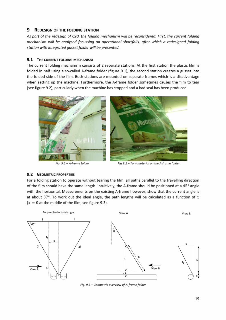
9 REDESIGN OF THE FOLDING STATION As part of the redesign of C20, the folding mechanism will be reconsidered. First, the current folding
mechanism will be analysed focussing on operational shortfalls, after which a redesigned folding
station with integrated gusset folder will be presented.
9.1 THE CURRENT FOLDING MECHANISM
The current folding mechanism consists of 2 separate stations. At the first station the plastic film is
folded in half using a so-called A-frame folder (figure 9.1), the second station creates a gusset into
the folded side of the film. Both stations are mounted on separate frames which is a disadvantage
when setting up the machine. Furthermore, the A-frame folder sometimes causes the film to tear
(see figure 9.2), particularly when the machine has stopped and a bad seal has been produced.
Fig. 9.1 – A-frame folder Fig 9.2 – Torn material on the A-frame folder
9.2 GEOMETRIC PROPERTIES
For a folding station to operate without tearing the film, all paths parallel to the travelling direction
of the film should have the same length. Intuitively, the A-frame should be positioned at a angle
with the horizontal. Measurements on the existing A-frame however, show that the current angle is
at about . To work out the ideal angle, the path lengths will be calculated as a function of
( at the middle of the film, see figure 9.3).
Fig. 9.3 – Geometric overview of A-frame folder

20
The angle is the unknown angle to be calculated. The total path length of the film is divided into
two sections, and (see figure 9.3). The length of the first section is in the plane perpendicular
to the folding triangle and can be calculated as follows:
( ) ( )
The remaining part in this plane is length :
( )
Now length can be calculated in the plane of view A:
( )
( ) ( )
Finally, the second section in the plane of view B can be calculated, as well as the total path length
:
√ ( )
( ) ( ) √ ( )
The total path length should be equal for all values of . Figure 9.4 shows a plot of ( )
( ) for different angles of . It can be seen that an optimal solution, where all path lengths
are equal, cannot be found. The optimum angle is found to be approximately , at which the
material at the outside shows less than 1% stretch (which is allowable). Small deviations from the
optimal angle lead to high stretch rates, making the angle to a critical design criterion.
Fig. 9.4 – Plot of ( ) ( ) for different angles
9.3 DESIGN SPECIFICATIONS
The main design specifications of the folding station are:
Both the A-frame folder and the gusset folder should be incorporated in one frame
The folder should be able to create , and gussets
Easy changeover between different gusset sizes
The folder should be able to fold the film without creating a gusset
The folder should have a ‘safety mechanism’ to avoid tearing the film

21
9.4 FINAL DESIGN
The CAD-model of the final design is shown in figures 9.5 and 9.6. Detailed drawings and an exploded
view can be found in the appendix. The station consists of a main folding triangle, which is an
equilateral triangle with sides of . The lower tip of the triangle is ‘cut off’ to create the
necessary space for the gusset folder. Exchangeable triangular plates can be bolted on to the main
folding triangle to adjust it for folding , or gussets.
The gusset folder (see figure 9.6) slides horizontally over two guiding bars. When the gusset size is
changed, the machine operator has to turn the red handle in order to move the gusset folder into
position. The spring loaded threaded bar is long enough to be adjusted between the most common
gusset sizes ( and ), so part B stays fixed and part A moves. While in operation, part A
can move with respect to part B to avoid tearing the film. Glacier bushings are used for smooth
guiding and the spring provides the necessary counterforce (the yellow parts in figure 9.6). Both the
angles of the main triangle and of the small gusset triangle can be adjusted, as the angle has to be set
very precise to avoid too large stretch rates in the film.
9.5 DESIGN FOR MANUFACTURING
The main folding triangle has to be a perfect
equilateral triangle with smooth edges to
prevent tearing the film. Because of the
limited possibilities in Safepak’s workshop, a
detailed step by step manufacturing plan was
created.
The step by step plan consists of 6 A3-pages
with detailed, chronologically ordered
manufacturing steps. An example of one of
these pages is shown in figure 9.7, some of
the pages can be found in the appendix as
well.
Fig. 9.5 – Final design of the folding station Fig. 9.6 – Detailed view of the gusset folder
Fig. 9.7 – One of the A3-pages of the detailed production plan
A B

22
10 SYSTEMATIC SET UP PROCEDURE
In order to reduce set up times and waste and to enhance product quality, a systematic set up
procedure for the various punches and the handle cut out of C20 will be presented. Currently,
operators don’t have a systematic method for setting up the machine. The punches, the handle cut
out and the ‘eye’ are randomly moved, hoping correctly sized bags will be produced. First, a short
overview of the relevant machine parts will be given, after which the systematic set up procedure will
be presented.
10.1 CURRENT SITUATION
There are in total 10 machine components to be relocated when there is a changeover on C20. These
10 components (8 punches, the handle cut out and the eye) are fixed on two different carriages: the
flying knife carriage en the punch carriage (see figure 10.1). When, for example, one of the punches
is out of position, the machine setters try to resolve the problem by moving the entire punch
carriage. This changes the position of all the punches, and thus bad quality products will be
produced. The same yields for the flying knife handle cut out and the position of the camera eye. The
eye determines where the bags are positioned in the machine, when its position is changed, all the
punches should be adjusted as well. Machine setters are not able to come up with a quick and
reliable set up procedure themselves, so there are very high waste rates during product changeovers.
Fig. 10.1 – Flying knife carriage and punch carriage on machine C20
10.2 SYSTEMATIC SET UP
The systematic set up of C20 will be implemented with the help of set up sheets (see figure 10.2 and
appendix B). For every different bag produced on the machine, a different set up sheet will be made.
The top section of the set up sheet contains the product size specifications: outer dimensions of the
bags, punch locations and tolerances. On the bottom part of the sheet the machine set up
parameters are listed. These consist of the locations of the two carriages and of the punches within
these carriages, the location of the eye and the width of the handle cut out.
To make sure that all machine setters use the same reference points for their measurements, metal
rulers will be bolted on to the holding bars of the punches, the flying knife handle cut out and the
Punch carriage
Flying knife carriage

23
holding bar of the camera eye (see figure 10.3 for an example). The setters were trained to use this
systematic set up procedure and should be able to get it right the first time in the future.
Fig. 10.2 – Systematic set up sheets Fig. 10.3 – Fixed metal rulers to improve set up accuracy
11 OTHER PROJECTS ON MACHINE C20
This chapter gives a brief overview of two other projects on machine C20. First, the redesign of the
flying knife attachment will be discussed, after which the pneumatic adjustments on the nip rollers
will be illuminated.
11.1 REDESIGN OF THE FLYING KNIFE ATTACHMENT
The flying knife attachment on machine C20 is used to make the handle cut outs. In its initial design,
two guiding rods and two threaded bars were used to adjust the size of the cut out. This highly
overconstrained construction caused the necessary problems: when operators tried to adjust the
attachment, the carriage got jammed and the guiding rods were scratched. In the new design, only
two threaded bars are used, connected with a timing belt (the orange parts in figure 11.1).
Furthermore, the red part is a newly designed guidance to support the film coming through.
Fig. 11.1 – Redesigned flying knife attachment
11.2 PNEUMATIC ADJUSTMENTS ON NIP ROLLERS
The nip rollers are used to pull the film through the machine. It was found that the machine didn’t
pull the same length of material for every bag, because the pressure of the nip rollers was too low
(slippage occurred). For this reason, larger pneumatic pistons were selected and implemented.

24
12 COST ESTIMATION In this chapter an estimation of the total re-engineering costs of machine C20 will be presented. The
total costs consist of, among others, workshop hours, production of outsourced parts and pneumatic
components. Some of the prices are estimates, such as workshop hours and materials, others are
prices as quoted by local suppliers or as found in supplier catalogues.
The costs per machine part are listed in table 12.1. It can be seen that both unwind systems are by
far the most expensive parts. The workshop hours and materials for the strip reel unwinds are the
highest debit item, because the two cantilevered reel mountings require quite some machining.
Some of the costs can be saved by using available items from unused machines, such as motor
gearbox combinations and pneumatic systems.
Unwind system main reel
2 x Safety chuck R 9.800
AC motor ( ) R 1.400
Variable speed drive for motor R 2.800
Gearbox R 1.200
2 x piston + pneumatic system R 15.300
Workshop hours and materials R 28.000
Electronics and control systems (incl. programming) R 12.000
R 70.500
Unwind system strip reels
2 x AC motor ( ) R 2.800
2 x Variable speed drive for motor R 5.600
2 x Gearbox R 2.400
Outsourced parts (folding triangles) R 2.000
Workshop hours and materials R 42.000
Electronics and control systems (incl. programming) R 8.000
R 62.800
Folding station
Outsourced parts (all folding surfaces) R 17.000
Workshop hours and materials R 8.000
R 25.000
Miscellaneous
Parts for flying knife redesign R 1.800
Pneumatic pistons for nip rollers R 2.100
R 3.900
Total R 162.200
Table 12.1 - Cost overview
The total re-engineering costs are R 162.200 (with the current exchange rate about € 15.200). As
there was no information about the exact downtime and waste of rates of machine 20 specifically, it
is hard to quantify the return on investment of the re-engineered machine.

25
13 SIDE PROJECT: ADJUSTABLE PUNCH CLAMP This section contains a brief overview of the design considerations made for the design of an
adjustable punch clamp. Main design criterion is the fatigue strength of the clamp, as the punch will
be operated 24/7 with a punch frequency of 300 punches per minute.
13.1 DESIGN SPECIFICATIONS
The design specifications as required by Safepak can be summarized as follows:
The clamp should fit the standard Pearl Technologies, Inc. pistons and the standard Safepak
clamping mechanism
The clamp should be adjustable perpendicular to the film with a range of and be able
to punch form the edge of the film
The clamp should last for at least 10 years, making 300 punches per minute 24/7 (a total of
punches)
Make use of standard/available aluminium sections
13.2 FINAL DESIGN
The only force acting on the clamp is the force of the spring, which was measured to be about .
Due to the cyclic loading of the clamp, the maximum allowable stress will be lower than the ultimate
tensile stress of the selected aluminium alloy. Of the wrought aluminium alloys, the series has
the best properties concerning fatigue strength, so this alloy is the recommended material to use.
When not available, , or series are the second best choice.
Looking at S-N curves for different aluminium alloys, the fatigue limit when doing load cycles is
less than of the yield stress of the material. The S-N curves for alloys 2024 & 7075 show that
when doing cycles, the maximum allowable stress in the material is less than . With
some basic calculations and a finite element model as verification (see figure 13.3), the punch is
designed such that the stresses do not exceed The final design and an actual manufactured
clamp can be seen in figures 13.1 and 13.2 respectively. The total price per clamp, when outsourcing
to a local workshop, is R 947 (with series aluminium).
Fig. 13.1 – Final design of the adjustable clamp
Fig. 13.2 – Exploded view Fig. 13.3 – ANSYS model of the clamp (high stresses are green)

26
14 CONCLUSION AND RECOMMENDATIONS In this section the conclusions and recommendations for future work can be found.
14.1 CONCLUSION
The main reason for re-engineering machine C20 was reducing downtime and waste rates. During
the evaluation of the current system, various operational shortfalls were found and improved in the
new design. For the main reel, a new tensioning system and line guide system were implemented.
Safety chucks will be used to enable machine operators to quickly change the reel. The strip reel
unwinds are now incorporated into the same frame as the main reel unwind, preventing alignment
problems in the rest of the machine. The tensioning system for the strip reels will make sure that
both the main film and the strip films have the same tension. The folding frame has been adjusted to
incorporate the gusset folder and a systematic set up plan has been created to assist machine
operators at job changeovers.
Of all these changes, the new systematic set up plan might be the one with the most impact. During
machine set up, operators wasted hundreds of meters of high quality, printed plastic film. After the
first test with the new set up plan, only 3 meters of material was wasted, which is a promising result.
The main benefits for machine C20 can be summarised as follows:
Increased efficiency
o Shorter set up and changeover times
o Possibility to speed up machine from 30 to 60 bags a second
o Less downtime thanks to more robust design
Better product quality
o Better seal quality thanks to tensioning systems and constant speed at unwind
station
o Better sized products thanks to pneumatic adjustments on nip rollers and systematic
set up plan
Less waste
o Systematic set up plan to reduce waste at machine set up
o Less rejected product batches thanks to better product quality
14.2 RECOMMENDATIONS
Unfortunately, not all machine parts were available before the publishing of this report. However, all
the engineering calculations and technical drawings are available at the company workshop, so it
would be wise to implement the changes as soon as possible.
Furthermore, out of cost considerations, an available shaft with cone grippers will be used to support
the main reel. To further shorten changeover times, an air shaft can be used. The same yields for the
strip reels: a cantilevered latching roller chuck, for example from the supplier “Double E USA”, could
further decrease changeover times.
Finally, operators should be trained on a regular basis to use the systematic set up plan.

27
15 REFERENCES
The following (supplier-)websites were consulted in the period 29-08-2011 to 30-11-2011:
Arvind Rubber (industrial rollers, safety chucks) www.arvindrubber.com
Bearing distributors (bearings and drives) www.italbearings.co.za
Delta electronics (motors, drives, sensors, alarms) www.delta.com.tw
Double E company (industrial rollers) www.doubleeusa.com
Festo (pneumatics) www.festo.com
FLT bearings (bearings) www.fltbearings.co.uk
Hudson sharp (plastic bag making machinery) www.hudsonsharp.com
IPTCI (cad models of flange mounted bearings) www.iptci.thomasnet.com
Italcuscinetti (flange mounted bearings) www.italcuscinetti.it
Niika (safety chucks) www.airtek-niika.com
Safepak (flexible packaging) www.flexiblepackaging.co.za
SKF (bearings) www.skf.com
Stone stamcor (safety chucks) www.stonestamcor.co.za
Structural drafting (standard steel profiles) www.structural-drafting-net-expert.com
The PROPAK Cape 2011 exhibition was visited on the 25th and
26th of October in the Cape Town International Convention
Centre. Advice and insight on relevant machinery was gained by
visiting stands of South African and international packaging
companies. Website: www.propakcape.co.za.

APPENDIX A – TECHNICAL DRAWINGS
On the next pages a few of the many technical drawings made during the internship can be found.
Not all drawings are included, because they were merely made for manufacturing purposes. The first
two A3 drawings are from the gusset folder with spring loaded safety mechanism. The other two
drawings are part of the detailed, step by step manufacturing plan for the equilateral triangle of the
A-frame folder, as described in chapter 9.

14
1
2
3
4
56
11
11
8 9
10 13
7
12
12
Nr. Part name Description QTY
1 TE.SubGusset.15092011.2.Part 1 See detailed drawings 1
2 TE.SubGusset.15092011.2.Part 2 See detailed drawings 1
3 TE.SubGusset.15092011.2.Part 3 See detailed drawings 1
4 TE.SubGusset.15092011.2.Part 4 See detailed drawings 1
5 TE.SubGusset.15092011.2.Part 5 See detailed drawings 1
6 TE.SubGusset.15092011.2.Part 6 See detailed drawings 1
7 Glacier bushing 25 inside, 28 outside, length > 20 mm 2
8 Spring Compression spring, length 25, 10 inside 1
9 Bearing SNR 6200ZZJ30 FM2 1
10 Circlip Circlip for 10 shaft 111 M4 bolt M4x0.7x20 212 M6 bolt M6x1.0x40 213 M3 grubscrew M3x0.5 114 M10 locknut M10x1.0 1
5 6 7 8
E
F
FACULTY OF ENGINEERING
PROJECTIONMETHOD DATEUNLESS STATED
OTHERWISE:TOLERANCES 0,5 MM
MATERIAL TITLE
SURFACE FINISHFILE / PART NAME
REV.
DIMENSIONS IN MILLIMETERS SHEET 1 OF 1
A3
D
E
F
C
1 2 3 4
B
A
321
5
C
D
4
6 7 8
A
B
5 6 7 8
E
F
PROJECTIONMETHOD
SCALE
DIMENSIONS IN MILLIMETERS SHEET 1 OF 1
Tom Eller
Grant Thorburn
15-9-2011
Not to scale
02
Subassembly Gutter - overview
Subassembly Gutter - overview
CHECKED
DRAWN
DRAWING NO.
TE.SubGusset.15092011.1

80
40 m
m M
16x1
.5th
read
on
outs
ide
16
10 -0,050
251
45°
X
Make groove for 10 circlipProvide sliding fit to 10 bearing
40
M3x0.5
10
Knurled surface finish
10
40
6
M6x
1.0
R12,5
140
2
55
402510 (4x)
2530 18
10
190
5
5
91
125
25
20
140
M16x1.5
20
M10x1.0
60
28
4
5
1010
20
50
150
10
190
150
145
15
M4x
0.7
10 d
eep
60°
563
3 mm filletson both sides
37°
Use M10x1.0x60 bolt and chamfer corner
Part 1 Part 2 Part 3 Part 4
Part 5
Part 6
No surface finish
No surface finish,just pollish guiding edges
Part nr. Material1 M10x1.0x60 bolt2 16 shaft, bright mild steel3 40 shaft, bright mild steel4 40x10 bar, bright mild steel5 190x125 plate, thickness 10, bright mild steel6 150x145 plate, thickness 6, stainless steel
5 6 7 8
E
F
FACULTY OF ENGINEERING
PROJECTIONMETHOD DATEUNLESS STATED
OTHERWISE:TOLERANCES 0,5 MM
MATERIAL TITLE
SURFACE FINISHFILE / PART NAME
REV.
DIMENSIONS IN MILLIMETERS
A3
D
E
F
C
1 2 3 4
B
A
321
5
C
D
4
6 7 8
A
B
5 6 7 8
E
F
PROJECTIONMETHOD
SCALE
DIMENSIONS IN MILLIMETERS SHEET 1 OF 1
Tom Eller
Grant Thorburn
15-9-2011
Not to scale
02See table above
Electroplate galvanized, unlessotherwise stated
Subassembly Gutter
Subassembly Gutter
CHECKED
DRAWN
DRAWING NO.
TE.SubGusset.15092011.2

30°
1430
6 (x5)
20011
5
415
715
1015
1315
1430
40
40 5
60°60
40
40
5
A
45
DETAIL A (1 : 5)
Production steps 1 and 2
Production step 4
1251
A
Production step 3
A
Part 1Quantity: 3
Part 2Quantity: 1
Production steps:Weld parts 1 together to form an equilateral1.triangle (all angles 60 )Weld part 2 to the assembly2.Cut off the tip of the triangle parallel3.to the upper L-barCut off the tip under a 45 angle4.
Part nr. Quantity Material
1 3 L-bar 40x40x5, length 1570Bright mild steel
2 1 L-bar 40x40x5, length 110Bright mild steel
5 6 7 8
E
F
FACULTY OF ENGINEERING
PROJECTIONMETHOD DATEUNLESS STATED
OTHERWISE:TOLERANCES 0,5 MM
MATERIAL TITLE
SURFACE FINISHFILE / PART NAME
REV.
DIMENSIONS IN MILLIMETERS SHEET 1 OF 1
A3
D
E
F
C
1 2 3 4
B
A
321
5
C
D
4
6 7 8
A
B
5 6 7 8
E
F
PROJECTIONMETHOD
SCALE
DIMENSIONS IN MILLIMETERS SHEET 1 OF 1
Tom Eller
--
16-9-2011
Not to scale
01Bright mild steel
Electroplate galvanized
Subassembly A-frame - 2
Subassembly A-frame
CHECKED
DRAWN
DRAWING NO.
TE.SubA.16092011.2

1430 20
30°
0 115
415
715
1015
1315
1430
Countersinked hole forM6 flathead (x5) Scale 1:4
Scale 1:4
6
50
R3
20
30°
0 115
415
715
1015
1315
1430
B
Countersinked hole forM6 flathead (x5)
R3
50
6
DETAIL B (1 : 4)
Initial cut line
Final cut line
Part 3Quantity: 1
Part 4Quantity: 2
Productionstep 7
1212
,2
C
200
DETAIL C (1 : 4)
Final cut line
Part 4
Part 4
20060°
35
10
35
Countersinked hole for M6 flathead (x2)
6
200
R3 (x4)
90
200
95,3 60
°
120°
R3110
200
77,9 60
°
120°
R3
Production steps:5. Manufacture all parts (parts 4 with the initial cut line, the same as part 3)6. Attach parts 3 and 4 to the assembly7. Mark the final cut line with a scriber8. Take both parts 4 off and cut according to the marked final cut line9. Re-assemble parts 410. Use part 5 to mark the locations of the 2
6 holes and drill them.
Part 5Quantity: 1
Part 6Quantity: 1
Part 7Quantity: 1
Note:Part 6 and 7 are similar topart 5, only the tip will be cut off to the specified dimension and an extra3 mm fillet is required.
Part nr. Quantity Material3 1 Bar 50x6, length 1605
Mild steel, chromed
4 2 Bar 50x6, length 1605Mild steel, chromed
5 1 Stainles steel plate, thickness 66 1 Stainles steel plate, thickness 67 1 Stainles steel plate, thickness 6
5 6 7 8
E
F
FACULTY OF ENGINEERING
PROJECTIONMETHOD DATEUNLESS STATED
OTHERWISE:TOLERANCES 0,5 MM
MATERIAL TITLE
SURFACE FINISHFILE / PART NAME
REV.
DIMENSIONS IN MILLIMETERS SHEET 1 OF 1
A3
D
E
F
C
1 2 3 4
B
A
321
5
C
D
4
6 7 8
A
B
5 6 7 8
E
F
PROJECTIONMETHOD
SCALE
DIMENSIONS IN MILLIMETERS SHEET 1 OF 1
Tom Eller
--
19-9-2011
Not to scale
01See table above
See table above
Subassembly A-frame - 3
Subassembly A-frame 2
CHECKED
DRAWN
DRAWING NO.
TE.SubA.16092011.3

APPENDIX B – SYSTEMATIC SET UP SHEET
A Bag width 365
B Bag length 526
C Gusset depth (central to print) 45
D Lip width 45
E Wicket hole pitch (12.7 mm diameter hole) 229
F Centrality of wicket hole 114
G Distance of wicket hole to bag opening 15
H Stress relief slit to bag opening 10
I Perforation length form bottom of bag 80
J Handle weld internally on unprinted area 5
K Handle cut out height from bottom of bag 25
L Perforation location, aligned to artwork Align
to print
M Handle top width 140
N Handle hole cut-out to bottom of bag 40
O Handle trim height 90
1 1.1 1.2
Carriage Cut-out Eye
131 225 333
2 2.1 2.2 2.3 2.4 2.5 2.6 2.7 2.8
Carriage CS8 CS8 P A12 A12 A12 SS1-20 Punch bar
245 116 341 467 378 201 151 78 344
Gusset triangle size: 90
Strip sealer settings: 80 apart
Production size specifications
Machine set up C20
Huggies Gold 3x58
61238629
Eye
1
1.1
2
2.1 2.2 2.3
2.7 2.6 2.5 2.4
G
J
E
C
Gusset fold
F
B
A
N
M
L
I
O D
Star punch Stress relief slit
H
Perforation
through all
layers
Peep hole
K
1.2
2.8
ALL DIMENSIONS IN MM

APPENDIX C – TMF REPORT
The Twente Mobility Fund supports students from the University of Twente that want to do a part of
their studies abroad. This chapter will give other students and the reader of this report insight on
practical matters besides the internship subjects.
C.1 SHORT DESCRIPTION OF THE STUDY OR TRAINEESHIP PROGRAM
From the 29th of August until the 30th of November 2011 I did an Internship at the South African
packaging company Safepak (Pty) Ltd. Safepak is situated in Cape Town and serves a variety of
industries throughout South Africa as a manufacturer of high quality flexible packaging products. The
internship was part of my 2 year master programme in Mechanical Engineering, specialization
Applied Mechanics.
My task was to optimize and redesign bag forming machine C20. First, the current machine was
evaluated with specific reference to the operational shortfalls. In consultation with Safepak, a final
design was selected from several drafts and detailed technical drawings were made. After several
reviews, the drawings were sent to the factory workshop and all the parts were produced.
During my internship at Safepak I gained a lot of practical experience. Mechanical design, motor,
gearbox and bearing selection, making technical drawings, getting feedback from the workshop and
training machine operators were all part of the assignment. Not less important is the experience of
working in a business environment, communicating with managers and other staff, both within and
outside the company. In the last week at Safepak I had the opportunity to present my achievements
to the management board, convincing them not only of the benefits for Safepak, but also of the
benefits for all other Dutch students to come.
C.2 LANGUAGE
While the most commonly spoken language in Cape Town is Afrikaans, English is understood by
almost all people as well. English and Afrikaans are only two of the 11 official languages in South
Africa. Another commonly heard language in Cape Town is Xhosa, recognisable by the different types
of "clicks'.
The English of the Capetonians is very understandable, which makes communicating very easy. The
Afrikaans language is, when spoken slowly, understandable as well: an estimated 90 to 95 percent of
the Afrikaans vocabulary is of Dutch origin. Warning signs in the factory such as "Moenie bewegende
masjinerie smeer of skoonmaak nie" ("Do not clean or oil moving machinery") are a good example of
the readability of Afrikaans for Dutch speaking students.
C.3 FINANCES
The South African Rand (SAR) is the local currency. The exchange rate between the rand and the euro
is very unstable and varies between 8 and 12 rand per euro. When I arrived in Cape Town (August
2011), paying my R4000 rent cost me 450 euro, when I left in December it was only 350 euro (the
exchange rate changed from 9 to 11.5 rand per euro).

There are a lot of unemployed people in South Africa, which is the main reason why foreigners are
not allowed to earn money in the country. To give an idea of the total costs of an internship in South
Africa, I will try to list the main expenses and prices in a city like Cape Town:
Return tickets are between 600 and 800 euros (when flying via Dubai with Emirates or via London
with British Airways). Renting a car costs between 350 and 450 euros a month, depending on extra's
like air conditioning and power steering, petrol costs 1 euro per litre. Renting a room in the city bowl
of Cape Town will set you back 300 to 400 euros a month. Although prices in the supermarkets are
quite similar to the prices in The Netherlands, going out for diner is cheaper (6 to 10 euros for a main
course). For an average weekend including trips, petrol, going out for diner and for a drink one
should estimate total costs at about 100 euros.
C.4 PREPARATION
I started the preparations for my internship about 7 months before going abroad. Once you have
found a suitable company, things can go really quick and can be arranged within a month. Finding a
company in the first place is what takes some time.
When going to South Africa, it is not necessary to arrange a visa before stepping on to the plane. For
students and tourists the visa will be arranged at the airport. You will get a 90 days internship visa
and when you are planning to stay longer, you can apply for a renewal at the Home Affairs office. You
do have to show a lot of documents when applying for the renewal: your passport, your return ticket,
a document proving that you have enough money, an invitation letter from the company stating that
you will not earn any money, a letter from your university stating that the internship is part of your
educational program and, last but not least, 45 euros.
I found my internship with the help of a fellow mechanical engineering student who did his
internship at the same company. For my room, my rental car and airport pickup I contacted an
internship bureau in Cape Town. For 100 euros they arrange you a room in a student house with
other Dutch students, a rental car, airport pickup and South African SIM card. The company is called
4exchange internships and they can be found at www.4exchange.nl.
C.5 ACCOMMODATION
As mentioned above, I arranged my accommodation with help of the internship bureau 4exchange.
Although their rooms might seem quite expensive (in fact they are), it is an advantage that they place
you in a house with other Dutch students. You will find that they are all of the same mind and that
it's a real treat to share the weekends with them.
As mentioned above, my room in the student house cost me R4000 a month (between 350 and 450
euros depending on the exchange rate). This price was including water and electricity but excluding
internet, which I had to buy for 7 euros per GB. Not all 4exchange houses have a washing machine,
but bringing it to the local laundry store at 1 euro a kg is not that bad.
C.6 CULTURE
Cape town is the oldest city of South Africa and parts of it are very western. When living in one of the
better neighbourhoods, one would not notice a difference with a big European city (except for the
beautiful surroundings such as the Table Mountain). When walking in a township however, the
differences between poor and rich become overwhelmingly clear.

Due to the history of South Africa, especially the time of the apartheid regime, the coloureds and
blacks are generally poorer than the white South Africans. About 70% of the Capetonians live in
townships, where the conditions are harsh. It is highly advisable not to go into a township alone, but
with a tour guide (mostly an inhabitant of a township) it is perfectly safe.
C.7 LEISURE TIME
Cape town and its surroundings offer great possibilities to make your leisure time in South Africa the
best time of your life! In Cape Town you can climb the table mountain, climb Lions Head by
moonlight, go to Robben Island, go to Cape point (the most south-western point of Africa), go shark
cage diving or skydiving and lots more. When you have a rental car the possibilities are even greater:
whale watching in Hermanus, hiking in Cederberg and visiting the Addo Elephant National Park are
just examples.
C.8 TRAVEL
Public transport in Cape Town is very unsafe (so is cycling), so unless your internship is at walking
distance from your accommodation, a rental car is highly advisable. During peak hours traffic can get
pretty bad, so I would advise taking an accommodation in the city centre. In this way you can always
drive against traffic, avoiding traffic-jams. When driving in and around Cape town, watch out for
mini-taxi busses. They drive like crazy and accidents happen with them on a daily basis.

APPENDIX D – ASSESSMENT FORM
On the next two pages the assessment form can be found as filled in by the factory manager, Grant
Thorburn.

1/4 (please continue on next page)
Assessment form ‘Internship’
Name student: Eller, T.K. (Tom; 0169625)
Master’s Programmes: Mechanical Engineering and Sustainable Energy Technology
Specialisation: AM (Applied Mechanics)
Company or institution offering the internship: Safepak
Department:
Location (city and country): N’dabeni, South Africa
Training period: 29-08-2011 till and including 25-11-2011
Name supervisor: Grant Thorburn ([email protected])
Note: If the information provided above is not correct, please fill in below the missing or corrected data:
City is Cape Town, N'dabeni is one of the industrial zones
excellent very good good satisfactory sufficient insufficient not
applicable
independence x
initiative x
technical knowledge x
critical judgement x
creativity x
output of work x
quality of work x
flexibility in case of
problems or criticism x
co-operation with
colleagues x
oral communication
skills x
written communication
skill x
total impression x

2/4
Could you give some remarks regarding Tom’s strongest points and on aspects which could be improved: Tom has great communication skills combined with excellent technical knowledge and analytical abilities. He
has a great work ethic and works independently. His independence is a strength but is also an area for
development, as working as part of a team and later leading a team is a key skill which will be crucial for his future career.
Would you be interested to supervise in the future other students from the University of Twente?
yes, from the following research areas: Safepak is a manufacturing company and can not offer research projects. Safepak can offer practical design projects, usually aimed at increasing the efficiency or for additional functionality of existing manufacturing machinery.
Safepak has been using students referred through a local company "4exchange Internships". As finding companies for internships is their business, I believe Safepak has an ethical obligation not to allow Safepak's contact details to be given to other students without the consent of "4exchange Internships".
do not know yet, because
no, because
Sometimes the report written by the trainee is considered confidential. Since recently all student’s reports are archived in our digital library, and possibly made public for third parties. Please indicate what is applicable to the report written by Tom:
the report is public and can be read by everyone the report is confidential, but can be accessed by students and employees of the University of Twente
the report is strictly confidential and will remain inaccessible to any other parties outside the agreed confidentiality loop
In case of the last option, could you indicate for how long the report is deemed confidential? N/A year
One final question, regarding feedback on our programme: Tom is now approaching the end of his Master’s programme in Mechanical Engineering. Do you have the feeling that certain aspects where missing in his education, which you would consider essential for a mechanical engineer? All the students I had, have had very little exposure to industrial pneumatics and their application in automation and machines. In our industry, we make extensive use of pneumatics and to a lesser degree
hydraulics. I have found a similar apparent gap with their exposure to bearings and bearing selection.
I am sure one of the leading companies like SKF for bearings, and Festo for pneumatics, could give them an introductory lecture/workshop or demonstration.
Date: 25/11/2011 Signature supervisor: Grant Thorburn
A signature is necessary only in case this document is printed and handed over to the student to deliver it to the Student Mobility Centre personally. If you sent it back by email yourself, the signature is unnecessary.
The Student Mobility Centre will make sure that the UT supervisor will receive a copy of this document for the final assessment of the student.