optimization design and hydrodynamic test on propeller ...isomase.org/jomase/vol.27 jan...
TRANSCRIPT
Journal of Aeronautical -Science and Engineering-, Vol.27
January 20, 2016
8 Published by International Society of Ocean, Mechanical and Aerospace Scientists and Engineers
Optimization Design and Hydrodynamic Test on Propeller Mini Submarine
Nurwidhi Asrowibowo, Mahendra Indiaryanto and Rina
Indonesian Hydrodinamic Laboratory (IHL), Agency for The Assessment an Aplication of Technology (BPPT), Indonesia *Corresponding author: [email protected] Paper History Received: 31-December-2015 Received in revised form: 15-January-2016 Accepted: 20-January-2016 ABSTRACT The defense equipment technology development which is in this case is the submarine research became an important subject and need to be further researched. One part of it is, designing driving components (propeller) of a mini-submarine with a high level of efficiency. Test models of mini-submarines of 22 m was used as a basis for developing propeller through scale models with the scale factor of 1:7. Expected propeller design optimization is capable of producing high effisensi currently working on the operational speed propeller. This research method is based on the results of the propeller design optimization, numerical simulations using Computer Fluid Dynamic (CFD ) and hydrodynamic test. The results of this study shows that the method applied here could provide a solution in the choice of an efficient propeller designs for mini-submarines 22 m. KEY WORDS: Mini Submarine, Propeller Optimization, Propeller Efficiency. NOMENCLATURE T Thrust Propeller (N) RT Resistance mini submarine (N) T thrust deduction factor TProp Propeller thurst (N) QProp Propeller toeque (Nm) n Propeller Rotational (rps) D Propeller Diameter (m)
VA Advance Velocity ρ Fluid density (kg/m3) �� Propeller efficiency �� Friction Force ��� Design Compressive Strain �� Critical Strain 1.0 INTRODUCTION According to Carlton [2], to design a propeller of a ship should include results of its resistance test (RT) and analysis of the ship itself. The test results will determine a thrust value of the propeller (T). This means that the design will be adapted to the propeller thrust required and the value of a thrust factor value based on a numerical study result. Equations related to these variabels is given in the following equation:
=�
( ��) (1)
From the above equation, it indicates that propeller design
optimization depends on variables obtained from its experiment. The experiment is done by using a mini-submarine model with a length of its hull of 3,14 m, and done in the Towing Tank basin belong to the IHL. The model is pulled by a carriage of the tank that moving forward at a speed model of 0,972 m/s to 2,722 m/s at a scale of 1 : 7. Moreover, it tested on a floating condition by using a foil as a holder of a model. Numerical simulation results using CFD as shown in Figure 1 indicates that a submarine is used as the model tested.
The value of resistance at every speed can be obtained both from the experiment (Figure 1 (a)) and simulations (Figure 1 (b)). The numerical simulation is performed to the submarine model using the Computer Fluid Dynamic (CFD) program. 3D image of the mini-submarine hull is adjusted based on the dimensions of the test model. Results of numerical simulation is used as a reference in providing an overview of the streamlined flow that

Journal of Aeronautical -Science and Engineering-, Vol.27
January 20, 2016
9 Published by International Society of Ocean, Mechanical and Aerospace Scientists and Engineers
occurs in the mini-submarine hull 22 m. Moreover, this figure also shows the simulation result of a pressure distribution while running at every operational speeds. By using the numerical simulation, a capacity of a load cell that will be use in the experiment in the Towing Tank can also be known.
(a) Resistance Test
(b) Numerical Simulation
Figure 1: Test models and numerical simulations of mini-submarines 22m
Main Dimension of mini submarine: Loa = 22.00 m Lwl at snorkle = 20.40 m Beam Diameter = 3.00 m Draught at snorkle = 2.60 m Depth = 5.13 m
2.0 BASIC THEORY Based on the equation (1) given in the previous subsection, the predicted value of the thrust propeller and its RPM propeller design of the mini-submarine is obtained for the operational speeds. Based on this, an iteration can be applied to be able to get the submarine propeller design iterations by using a few existing
theoretical approaches. Approach theory applied in this research is by using an open water tables from existing series and taking into account the value of its thrust and efficiency. Once the simulation is finished, a skew angle is added on the propeller design to reduce effects of cavitation on the propeller tip area.
Second approach is applied by using the open source program, i.e. Open Prop V.2.4.6 that combined into the Matlab program, where some additional input data can be entered, such as vessel speed, rpm, diameter, and thurst as an initial design of the propeller. The estimated thrust value is then determined using Equation (1). The lifting line theory and Matlab program are applied to design the mini-submarine propeller and to get the outline as well as the thickness of the propeller blade. From running matlab program, some results are obtained in the form of an outline along the thickness of the propeller and propeller efficiency. Where the blade resulting outline is from the type of symetrical blade so it needs to do skew propeller addition to reduce the level of cavitation occurs on the propeller tip area. Based on the results obtained from the iteration, the design of drawings propeller in the form of working drawings and 3D propeller can be choosen based on the highest efficiency of the propeller. The results of a mini propeller design iterations can be seen in Figure 2.
0.04
4
15°
0.042
0.01
4
0.04
0
13°48°
42°12°
15° 50°
35°13°
14° 27°
15° 20°
17° 11°
2°19°
RIGHT HAND PROPELLER
-
1:1
R-0
1 OF 1MAHENDRA
NURWIDHI
NURWIDHI
DESAIN PROPELLER KAPAL SELAM
SINAS RISTEK
-
-
DESIGN 1
-
-
(a1) (b1)
RIGHT HAND PROPELLER
-
1:1
R-0
1 OF 1MAHENDRA
NURWIDHI
NURWIDHI
DESAIN PROPELLER KAPAL SELAM
SINAS RISTEK
-
-
DESIGN 1
-
-
(a2) (b2)
PR I NC IP LE PAR TI CU LA RS SH I P
DI AMETER
AE/ A0
P/ D
PI TCH
N UMB ER OF B LADE
R PM
1. 4 M
1. 0 71
1. 5 0 M
7 ( 5 4 DE G)
2 4 0 r p m
0 . 8 8
RIGHT HAND PROPELLER
-
1:1
R-0
1 OF 1MAHENDRA
NURWIDHI
NURWIDHI
DESAIN PROPELLER KAPAL SELAM
SINAS RISTEK
-
-
DESIGN 1
-
-
Ex p a n d e d Vi e w
R0 ,7
R0 ,6 3
R0 ,5 6
R0 ,4 9
R0 ,4 2
R0 ,3 5
R0 ,2 8
R0 ,2 1
R0 ,14
TE LE
Tr a n sve r se Vi e w
1,0 7 1
1,0 7 1
1,0 7 1
1,0 7 1
1,0 7 1
1,0 7 1
1,0 7 1
1,0 7 1
1,0 7 1
Pi t c hDi s t r i b u t i o n0 ,0 0 2 11,0 0 R
0 ,0 10 0 80 ,9 0 R
0 ,0 15 9 60 ,8 0 R
0 ,0 2 18 40 ,7 0 R
0 ,0 2 7 7 20 ,6 0 R
0 ,0 3 3 60 ,5 0 R
0 ,0 3 9 4 80 ,4 0 R
0 ,0 4 5 3 60 ,3 0 R
0 ,0 5 12 40 ,2 0 R
Ta p er 1: 16 ,0 0
P r o f i l e Vi e w
(a3) (b3) Figure 2: Design Iterations of Propeller

Journal of Aeronautical -Science and Engineering-, Vol.27
January 20, 2016
10 Published by International Society of Ocean, Mechanical and Aerospace Scientists and Engineers
Based on the iterations propeller design of the above, it can be seen the initial characteristics of each propeller design. Therefore, Table 1 can be used to choose the propeller for further analysis.
Table 1: Propeller Design Specifications
No Specification Propeller Type
(a1b1) (a2b2) (a3b3) 1. RPM 250 200 240 2. Diameter (m) 1.4 1.4 1.4 3. Thrustcoefficient KT 0.15 0.3084 0.214 4. Torquecoefficient KQ 0.022 0.0624 0.0353 5. Estimates Efficiency 0.51 0.6934 0.709 6. Pitch diameter ratio 0.7 1.071 0.816
From the above table, the third propeller design is chosen. It
has the highest efficiency level than other propeller designs. Based on this selection, it is decided that the primary measure of propeller models is made with a scale of 1 : 7.
Diameter propeller models = 0.20m P/D = 0.816 Ae/Ao = 0.880 Blade = 7 Scale = 1:7
Since there are changes in outline with the additional
propeller blade skew, the CFD analysis needs to be redone. The additional skew on the propeller blade will have impacts on the decline in efficiency that accompanied the rising value of the advance coefficient. But the effect is not too significant in compare with the previous propeller design.
One of the objective in this research is to determine the efficiency of a propeller that has been designed. To do this, the efficiency of the actual propeller open water tests are conducted in the Towing Tank. Open water test is carried out using a propeller dynamometer of the IHL. With this test result, the value of the model propeller thrust and torque are measured by varying the speed of propeller models tested. The value of thrust (T) and torque (Q) are generated subsequently, and used in the calculation of thrust coefficient and torque coefficient KT, KQ, based on the advanced speed coefficient (J). KT, KQ and J can be defined by the following equation [2]:
K� = ��� ��
ρ � η� � �� (2)
�� = ��� ��
ρ � η�� �� (3)
= !"
# � � (4)
The propeller efficiency can be presented by the following
equation [2]:
�$ =% � &'
(π � &)
(5)
To know the value of cavitation occurs on a propeller, the
model propeller needs to be tested in a cavitation tunnel of the IHL. Cavitation noise is the largest component of the propeller
noise, especially on ships moving at a high speed. Singing noise caused by vibrations that arise as a result of the curvature blade propellers. The amount of noise frequency is dependent on the magnitude of vibration frequencies. 3.0 METHODOLOGY The experiment carried out in the Towing Tank, is applied to determine the performance results of the propeller designed. The research methodology can be shown as follows :
Propeller
efficiency data
on the first
year of study
Propeller
design in the
first year of
study The new design
is more optimal
than the first year
and a numeric
calculation using
CFD
Modeling of new high-
efficiency propeller and
suitable for use onboard
submarines mini 22m
Produce propellers with high efficiency models
Figure 3: Work Flow The steps of research given in Figure 3 are as follows : • Data collection and efficiency propeller designs which have
been obtained previously is then used as a basic reference to get a better design.
• Recalculate using Matlab and numerical approach based on the data from the open water so that it will obtain baseline characteristics of the model propeller.
• Perform numerical simulation (CFD) to create a 3 - dimensional design drawings propeller in a solid form . This calculation is done since the outline changes to the previous design models with the additional propeller skew on propeller blade at around 540. The CFD is also applied to get an overview of the characteristics of a propeller that has been redesigned.
• Making the model propeller suitable as the working drawings that can be seen in Figure 2 (a3b3). Based on these figures, the table offset and table measurements that will be used to create a model propeller blade 7 can be determined.
• Model propeller generated will be tested in the Towing Tank to know the characteristics and efficiency through the open water test.
Dimension of the Towing Tank at IHL: Lenght = 234.5 m (including harbor) Width = 11.0 m Depth = 5.5 m Max Speed Carriage = 7.0 m/sec Max Aceleration = 1.0 m/sec2
4.0 RESULT AND DISCUSSION
The 3D program is required to get the three -dimensional images of the propeller, so that it can be used for meshing as shown in Figure 4 (a). The propeller model need to mesh to break the measuring object into an infinite element, and make it easy for a
Journal of Aeronautical -Science and Engineering-, Vol.27
January 20, 2016
11 Published by International Society of Ocean, Mechanical and Aerospace Scientists and Engineers
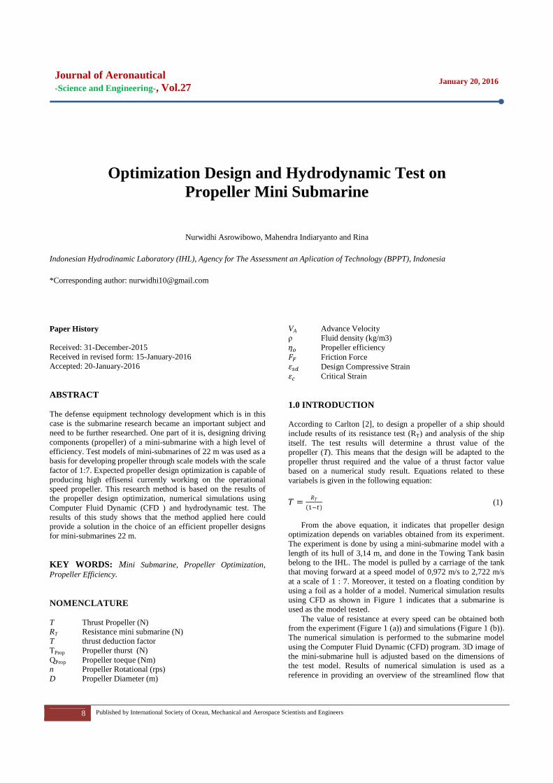
computer to calculate the finite form elements. The finite elements are necessary to obtain the results of numerical simulation in the form of Computer Fluid Dynamic (CFD).
(a) (b) Figure 4: Meshing and CFD Analysis
During the meshing process using the CFD, the steps to run
the program is similar with the steps done during the open water test in the Towing Tank. From the results of numerical simulation using the CFD, thrust and torque values obtained at any speed in running. Equation (3) and (4) is used to obtain the coefficient of propeller thrust and torque coefficient. Equation (5) is used to obtain the value of the efficiency of the propeller. The results of these calculations can be shown in Table 1 with the maximum efficiency value of 0.689 where it is comparable to the coefficient of the torque and thrust coefficient of 0.257 and 0.436 respectively. Based on the experimental result, it is known that the propeller is able to work efficiently at the value of J 0.735. Based on data from Table 2, the characteristics of the propeller can be known. By doing the experiment, the propeller characteristics designed gives comparable results between the numerical and experimental.
Table 2: Result Numerica Simulation
J Thurst (n)
Torque (Nm)
KT 10KQ h
0.184 71.602 2.194 0.400 0.612 0.191 0.276 69.707 2.142 0.389 0.598 0.286 0.367 65.888 2.062 0.368 0.575 0.374 0.459 60.065 1.942 0.335 0.542 0.453 0.551 55.148 1.841 0.308 0.514 0.526 0.643 50.692 1.684 0.283 0.470 0.616 0.735 46.020 1.563 0.257 0.436 0.689 0.827 36.086 1.510 0.201 0.421 0.629 0.919 26.771 1.456 0.149 0.406 0.538 1.011 20.751 1.345 0.116 0.375 0.497 1.102 15.828 1.235 0.088 0.345 0.450
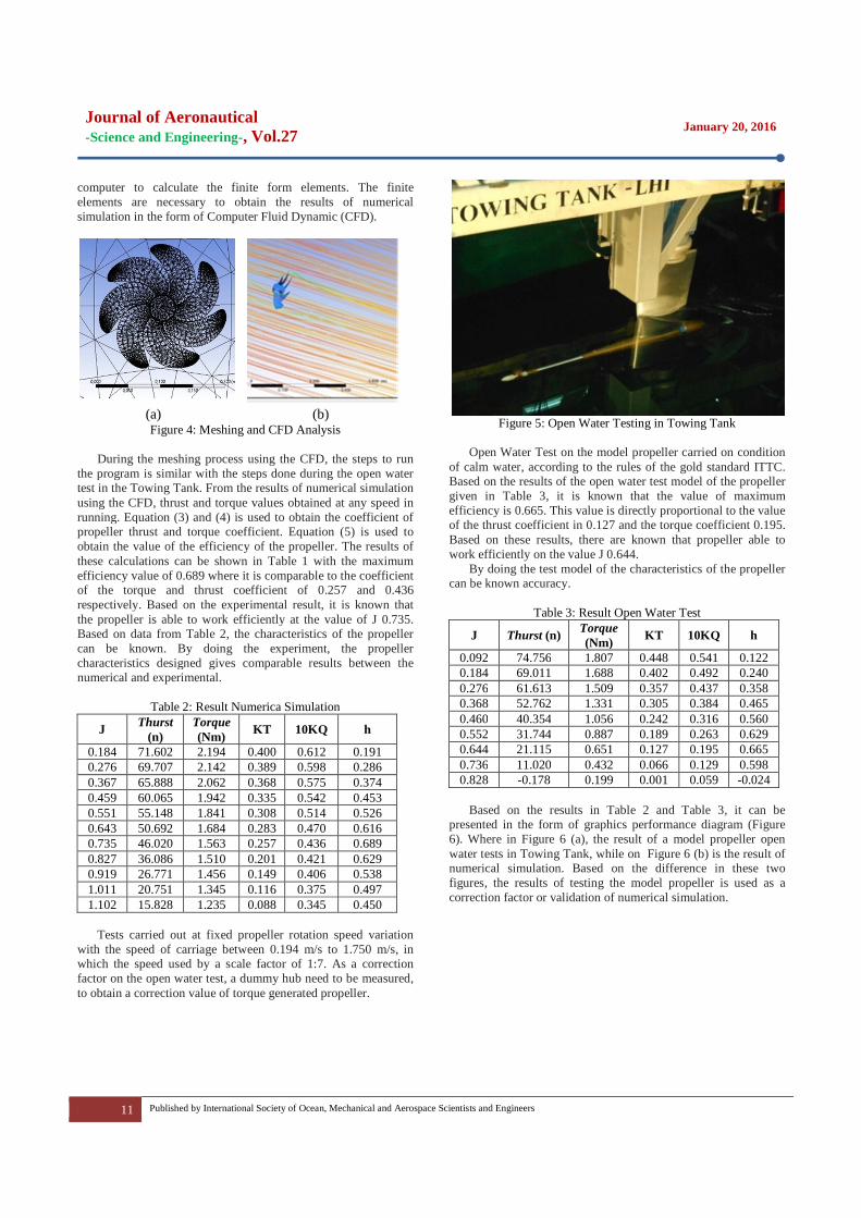
Tests carried out at fixed propeller rotation speed variation
with the speed of carriage between 0.194 m/s to 1.750 m/s, in which the speed used by a scale factor of 1:7. As a correction factor on the open water test, a dummy hub need to be measured, to obtain a correction value of torque generated propeller.
Figure 5: Open Water Testing in Towing Tank
Open Water Test on the model propeller carried on condition
of calm water, according to the rules of the gold standard ITTC. Based on the results of the open water test model of the propeller given in Table 3, it is known that the value of maximum efficiency is 0.665. This value is directly proportional to the value of the thrust coefficient in 0.127 and the torque coefficient 0.195. Based on these results, there are known that propeller able to work efficiently on the value J 0.644.
By doing the test model of the characteristics of the propeller can be known accuracy.
Table 3: Result Open Water Test
J Thurst (n) Torque (Nm)
KT 10KQ h
0.092 74.756 1.807 0.448 0.541 0.122 0.184 69.011 1.688 0.402 0.492 0.240 0.276 61.613 1.509 0.357 0.437 0.358 0.368 52.762 1.331 0.305 0.384 0.465 0.460 40.354 1.056 0.242 0.316 0.560 0.552 31.744 0.887 0.189 0.263 0.629 0.644 21.115 0.651 0.127 0.195 0.665 0.736 11.020 0.432 0.066 0.129 0.598 0.828 -0.178 0.199 0.001 0.059 -0.024
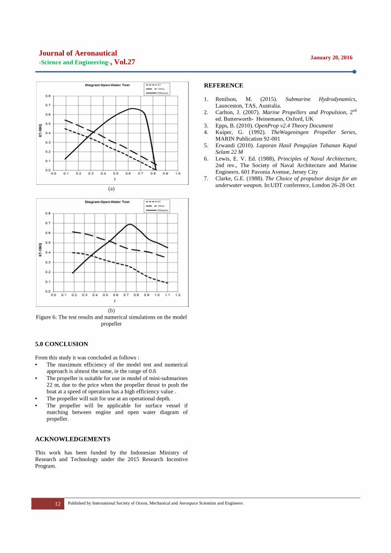
Based on the results in Table 2 and Table 3, it can be
presented in the form of graphics performance diagram (Figure 6). Where in Figure 6 (a), the result of a model propeller open water tests in Towing Tank, while on Figure 6 (b) is the result of numerical simulation. Based on the difference in these two figures, the results of testing the model propeller is used as a correction factor or validation of numerical simulation.
Journal of Aeronautical -Science and Engineering-, Vol.27
January 20, 2016
12 Published by International Society of Ocean, Mechanical and Aerospace Scientists and Engineers
(a)
(b)
Figure 6: The test results and numerical simulations on the model propeller
5.0 CONCLUSION From this study it was concluded as follows : • The maximum efficiency of the model test and numerical
approach is almost the same, ie the range of 0.6 • The propeller is suitable for use in model of mini-submarines
22 m, due to the price when the propeller thrust to push the boat at a speed of operation has a high efficiency value .
• The propeller will suit for use at an operational depth. • The propeller will be applicable for surface vessel if
matching between engine and open water diagram of propeller.
ACKNOWLEDGEMENTS This work has been funded by the Indonesian Ministry of Research and Technology under the 2015 Research Incentive Program.
REFERENCE 1. Renilson, M. (2015). Submarine Hydrodynamics,
Launceston, TAS, Australia. 2. Carlton, J. (2007). Marine Propellers and Propulsion, 2nd
ed. Butterworth- Heinemann, Oxford, UK 3. Epps, B. (2010). OpenProp v2.4 Theory Document 4. Kuiper, G. (1992). TheWageningen Propeller Series,
MARIN Publication 92-001 5. Erwandi (2010). Laporan Hasil Pengujian Tahanan Kapal
Selam 22 M 6. Lewis, E. V. Ed. (1988), Principles of Naval Architecture,
2nd rev., The Society of Naval Architecture and Marine Engineers. 601 Pavonia Avenue, Jersey City
7. Clarke, G.E. (1988). The Choice of propulsor design for an underwater weapon. In:UDT conference, London 26-28 Oct