optimization course rome 05_05_2015_fp
TRANSCRIPT

Optimization and
Performance-Based Design (PBD)
(service / ultimate / extreme scenarios)
Francesco PetriniStroNGER s.r.l.
Corso di OTTIMIZZAZIONEFacolta’ di Ingegneria Civile e Industriale
Sapienza Universita’ di Roma
Roma, 06 Maggio 2015
Object of the course
2Corso di Dottorato: Introduzio ne all'o7mi zzazione struttural e Roma, 06 Maggio 2015
Prof.-Ing. Franco Bontempi, Ing. Francesco Petrini, Ph.D.
• Introduction of basic and advanced ideas and
aspects of structural design without to much
stress on the analytical apparatus but with
some insigth on the computational
techniques.

Object of this lecture
• To show some of the issues related with the optimization of real complex structural systems
• Examples of practical design cases where the optimization has been conducted with respect to specific performance requirements
– Offshore wind turbines (general)
– High rise buildings
• Regarding the behaviour under wind (service)
• Regarding the robustness under fire (ultimate)
3Corso di Dottorato: Introduzio ne all'o7mi zzazione struttural e Roma, 06 Maggio 2015
Prof.-Ing. Franco Bontempi, Ing. Francesco Petrini, Ph.D.
INTRODUCTION • Who I am
• Background concepts (optimization and PBD)
4FB

WHO I AM
5

Education, Milestones, Research topics (2005-2015)
Jul
20
09
Au
g2
00
9
Oct
20
04
Ma
r 2
00
6
No
v 2
00
8
PhD StudentPG
Assistant
Ma
r 2
00
9A
pr
20
09
MS
c d
eg
ree
(la
ure
a)
Jan
20
07
Jan
20
09
P.E
.
Ma
r 2
00
5
No
v 2
00
5
Jan
20
05
Jan
20
06
Jan
20
08
(Sapienza University of Rome)
Jun
20
05
Ph
D d
eg
ree
Jan
20
10
Post-Doc Research Associate
Ma
r 2
01
2
Associate Researcher
Ma
y2
01
1
Jan
20
11
Ap
r2
01
2
Jan
20
13
Jan
20
12
Jan
20
14
Jun
20
14
No
v2
01
3
Jan
20
15
(Sapienza
University
of Rome)
Research Spin-off
Company. Co-founder and Director
Structures of the Next Generation:
Energy harvesting and Resilience
No
v2
01
2
Ma
r 2
01
4
(Sapienza University of Rome)
Aerodynamics and Aeroelasticity
PBD for Wind
PBD for Wind, Earthquake, Fire, Blast
Resilience
Energy Harvesting
Associate Researcher
Ma
r 2
01
5
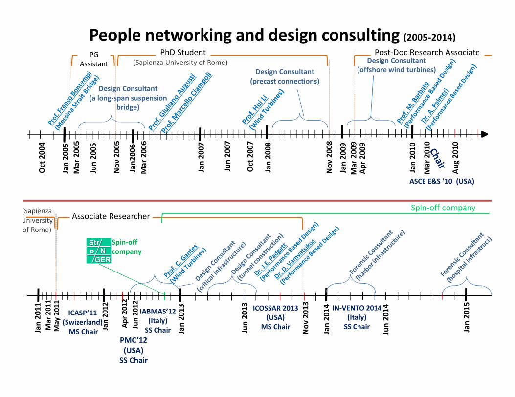
People networking and design consulting (2005-2014)O
ct 2
00
4
Oct
20
07
Ma
r 2
00
6
No
v 2
00
8
PhD StudentPG
Assistant
Ma
r 2
00
9A
pr
20
09
Design Consultant
(a long-span suspension
bridge)
Design Consultant
(precast connections)
Design Consultant
(offshore wind turbines)
Jan
20
07
Jan
20
09
Ma
r 2
00
5
No
v 2
00
5
Jan
20
05
Jan
20
06
Jun
20
07
Jan
20
08
(Sapienza University of Rome)
Jun
20
05
ASCE E&S ’10 (USA)
Jan
20
10
Post-Doc Research Associate
Ma
r 2
01
0
Au
g2
01
0
Spin-off
company
IABMAS’12
(Italy)
SS ChairMa
r 2
01
1
Associate Researcher
Ma
y2
01
1
ICASP’11
(Swizerland)
MS ChairJan
20
11
Ap
r2
01
2
Jan
20
13
PMC’12
(USA)
SS Chair
Jan
20
12
Jun
20
13
Jan
20
14ICOSSAR 2013
(USA)
MS Chair
Jun
20
14
No
v2
01
3IN-VENTO 2014
(Italy)
SS Chair Jan
20
15
(Sapienza
University
of Rome)
Spin-off company
Jun
20
12
0
0.1
0.2
0.3
0.4
0.5
0.6
0.7
0.8
0.9
1
0 5 10 15 20 25 30 35
P(Av > av*|Vm(zdeck))
Vm(zdeck) [m/s]
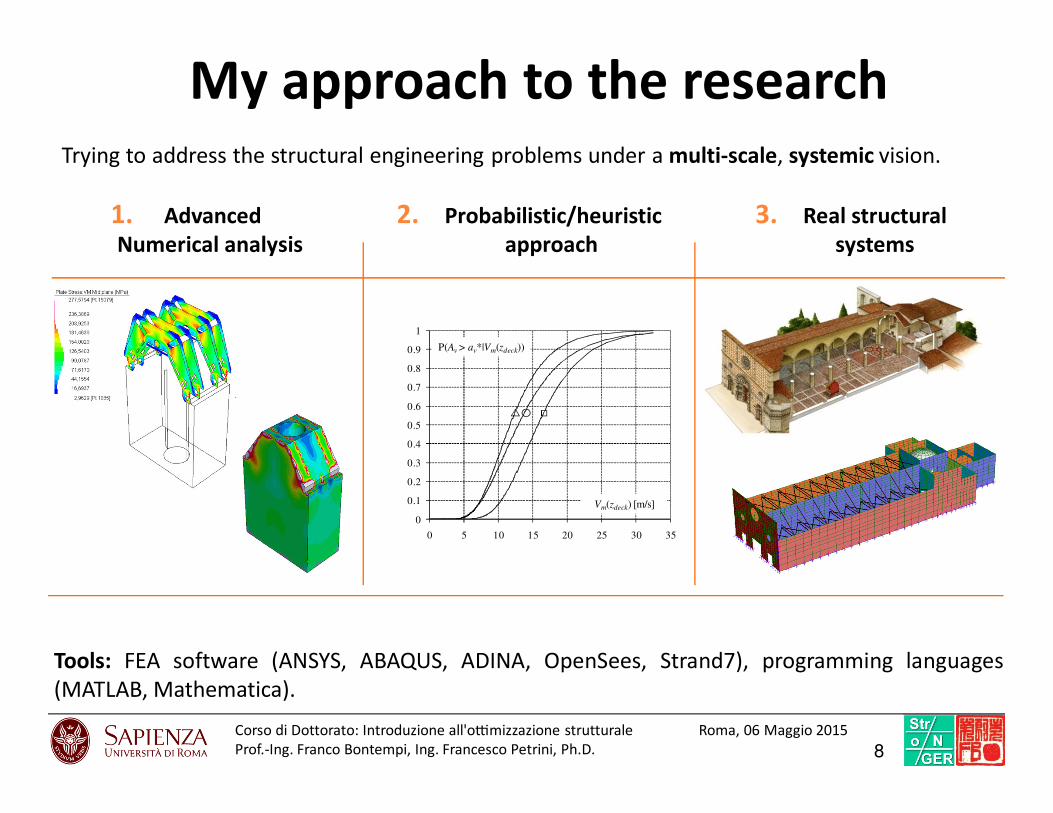
My approach to the research
1. Advanced
Numerical analysis
2. Probabilistic/heuristic
approach
3. Real structural
systems
Tools: FEA software (ANSYS, ABAQUS, ADINA, OpenSees, Strand7), programming languages
(MATLAB, Mathematica).
Trying to address the structural engineering problems under a multi-scale, systemic vision.
8Corso di Dottorato: Introduzio ne all'o7mi zzazione struttural e Roma, 06 Maggio 2015
Prof.-Ing. Franco Bontempi, Ing. Francesco Petrini, Ph.D.

BACKGROUND CONCEPTS
9
• Optimization problem formulation
• Optimization issues in complex systems
• Performance-Based Design
Optimization problem formulation
10FP

Objective
Funcrion
Optimization problem formulation
Unconstrained Design space
Constrains
Constrained Design space
We must find the minimum of a certain Objective Function f, depending on certain Design
Variables (DV) x1,…,xn subjected to a number of constrains and by bounding the values of a certain
number of state variables (SV)
nn11
n LSV,,LSV,RXx,0)x(g,0)x(hbeing)x(fmin ≤≤⊆∈≤= K
Constrains Design variables State variablesObjective Functions
Von Mises
stresses
11Corso di Dottorato: Introduzio ne all'o7mi zzazione struttural e Roma, 06 Maggio 2015
Prof.-Ing. Franco Bontempi, Ing. Francesco Petrini, Ph.D.

Esposizione formale del problema
.RXe
,0)(,0)(
,0)(,0)(asottoposto
)(min
n
21
11
⊆∈
≤=
≤=
x
xx
xx
x
mm gh
gh
f
MMProcedura
Operativa
Problema vincolato
Funzioni barriera
Problema non vincolato
Esplorazione locale
Optimization problem formulation in ANSYS©
12Corso di Dottorato: Introduzio ne all'o7mi zzazione struttural e Roma, 06 Maggio 2015
Prof.-Ing. Franco Bontempi, Ing. Francesco Petrini, Ph.D.
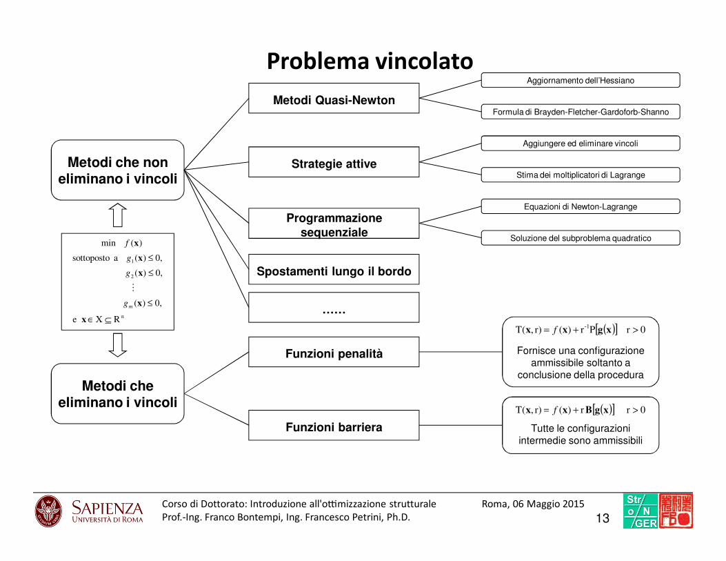
Problema vincolato
13Corso di Dottorato: Introduzio ne all'o7mi zzazione struttural e Roma, 06 Maggio 2015
Prof.-Ing. Franco Bontempi, Ing. Francesco Petrini, Ph.D.
Metodi che non eliminano i vincoli
Metodi che eliminano i vincoli
Funzioni penalità
Funzioni barriera
n
2
1
RXe
,0)(
,0)(
,0)(asottoposto
)(min
⊆∈
≤
≤
≤
x
x
x
x
x
mg
g
g
f
M
Spostamenti lungo il bordo
Metodi Quasi-Newton
Aggiornamento dell’Hessiano
Formula di Brayden-Fletcher-Gardoforb-Shanno
Programmazione sequenziale
Equazioni di Newton-Lagrange
Soluzione del subproblema quadratico
Aggiungere ed eliminare vincoli
Stima dei moltiplicatori di Lagrange
( )[ ] 0rPr)(r),T(-1 >+= xgxx f
Fornisce una configurazione ammissibile soltanto a
conclusione della procedura
( )[ ] 0rr)(r),T( >+= xgBxx f
Tutte le configurazioni intermedie sono ammissibili
Strategie attive
……
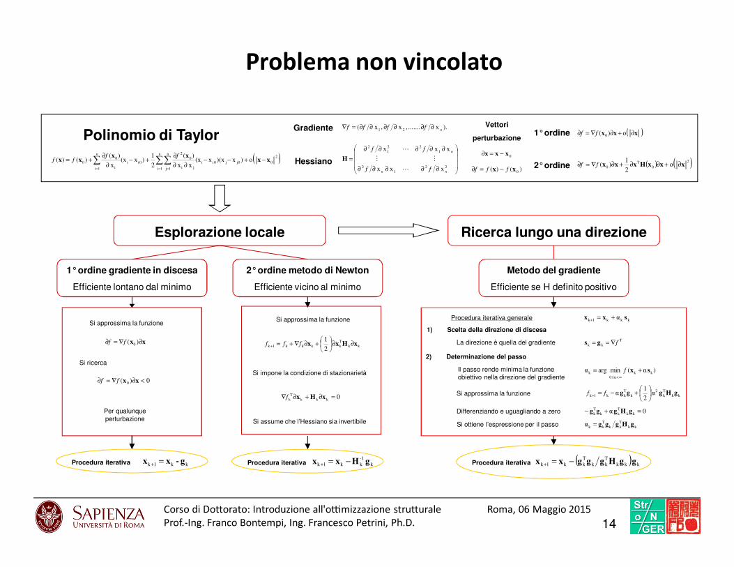
Problema non vincolato
Polinomio di Taylor
( )2
00jj0ii
n
1i
n
1j ji
0
2
0ii
1 i
00
ο)x)(xx(xxx
)(
2
1)x(x
x
)()()( xx
xxxx −+−−
∂∂
∂+−
∂
∂+= ∑∑∑
= ==
ffff
n
i
).x.......,x,x(21 n
ffff ∂∂∂∂∂∂=∇
∂∂∂∂∂
∂∂∂∂∂
=22
1
2
1
22
1
2
xxx
xxx
nn
n
ff
ff
L
MM
L
H
Gradiente
Hessiano0
xxx −=∂
)()(0
xx fff −=∂
Vettori
perturbazione1°ordine
2°ordine
( )xxx ∂+∂∇=∂ ο)( 0ff
( ) ( )2
0
T
0 ο2
1)( xxxHxxx ∂+∂∂+∂∇=∂ ff
Esplorazione locale
1°ordine gradiente in discesa
Efficiente lontano dal minimo
xx ∂∇=∂ )( 0ff
Si approssima la funzione
0)( 0 <∂∇=∂ xxff
Si ricerca
Per qualunque
perturbazione
kk1k g-xx =+Procedura iterativa k
-1
kk1k gHxx −=+
2°ordine metodo di Newton
Efficiente vicino al minimo
Procedura iterativa
Si approssima la funzione
kk
T
kkkk1k2
1xHxx ∂∂
+∂∇+=+ fff
Si impone la condizione di stazionarietà
0kkk
T
k =∂+∂∇ xHxf
Si assume che l’Hessiano sia invertibile
Ricerca lungo una direzione
Metodo del gradiente
Efficiente se H definito positivo
( ) kkk
T
kk
T
kk1k ggHgggxx −=+Procedura iterativa
Procedura iterativa generale kkk1k α sxx +=+
1) Scelta della direzione di discesa
2) Determinazione del passo
T
kk f∇== gsLa direzione è quella del gradiente
)α(minargαkk
α0
ksx +=
∞<≤
fIl passo rende minima la funzione
obiettivo nella direzione del gradiente
Si approssima la funzione kk
T
k
2
k
T
kk1kα
2
1α gHggg
+−=+ ff
Differenziando e uguagliando a zero 0αkk
T
kk
T
k=+− gHggg
Si ottiene l’espressione per il passo kk
T
kk
T
kkα gHggg=
14Corso di Dottorato: Introduzio ne all'o7mi zzazione struttural e Roma, 06 Maggio 2015
Prof.-Ing. Franco Bontempi, Ing. Francesco Petrini, Ph.D.

First order Optimization method (FOOM)
One introduces the following unconstrained objective function:
( ) ( ) ( ) ( ) ( )
++++= ∑ ∑∑∑
= ===
2 31 m
1i
m
1i
iwih
m
1i
ig
n
1i
ix
0
wPhPgPqxPq,Qf
fx
( )λ2
ii
iig
αg
ggP
+=
λ is a large integer so that the function will be very large
when the constraint is violated and very small when it is not
Q is the dimensionless unconstrained objective function,
Px is the exterior penalty functions applied to the design variables,
Pg, Ph, and Pw are penalties applied to the constrained design and state variables,
f0 is the reference objective function value that is selected from the current group of design sets
q is the response surface parameter .
For each optimization iteration (j) a search direction vector d(j) is devised. The next iteration (j+1) is obtained from the
following equation:
( ) ( ) ( )jj
j1j s dxx +=+
( ) ( )( ) ( )1j
1jk
jj rq,Q −−+−∇= dxd
( )( ) ( )( )[ ] ( )( )( )( ) 2
1j
jT1jj
1j
q,Q
q,Qq,Qq,Qr
−
−
−
∇
∇∇−∇=
x
xxx
where sj is the line search parameter, and
The key to the solution of the global minimization of Q relies on the sequential generation of the search directions and on
internal adjustments of the response surface parameter (q).
ANSYS Inc. (2008). ANSYS Theory reference
15Corso di Dottorato: Introduzio ne all'o7mi zzazione struttural e Roma, 06 Maggio 2015
Prof.-Ing. Franco Bontempi, Ing. Francesco Petrini, Ph.D.

Sub-problem approximation method (SAM)
• Generazione delle funzioni approssimate
(((( )))) (((( )))) errorexfxf ++++==== ∑∑∑∑∑∑∑∑∑∑∑∑==== ========
++++++++====n
1i
n
1j
jiij
n
1i
ii0xxbxaaf i coefficienti ai e bij si determinano con
una interpolazione ai minimi quadrati
(((( )))) (((( )))) (((( ))))(((( ))))2n
1j
jjj2d
ffΦE ∑∑∑∑====
−−−−==== i pesi Φ vengono associati ad ogni configurazione in base alla loro
ammissibilità o al valore della funzione obiettivo
• Minimizzazione del problema approssimato
Si introducono le funzioni barriera per eliminare i vincoli
(((( )))) (((( )))) (((( ))))
++++++++==== ∑∑∑∑∑∑∑∑
========
m
1i
i
n
1i
ik0k gGxXpffp,xF
Si determina il minimo imponendo le condizioni di stazionarietà
• Convergenza
ττττ, ρρρρ sono, rispettivamente, le tolleranze delle
variabili di progetto e della funzione obiettivo
(((( )))) (((( ))))
(((( )))) (((( )))) τff
τff
bj
1jj
≤≤≤≤−−−−
≤≤≤≤−−−− −−−− (((( )))) (((( ))))
(((( )))) (((( )))) n1,2,3,...iρxx
n1,2,3,...iρxx
i
b
i
j
i
i
1j
i
j
i
====≤≤≤≤−−−−
====≤≤≤≤−−−− −−−−
16Corso di Dottorato: Introduzio ne all'o7mi zzazione struttural e Roma, 06 Maggio 2015
Prof.-Ing. Franco Bontempi, Ing. Francesco Petrini, Ph.D.
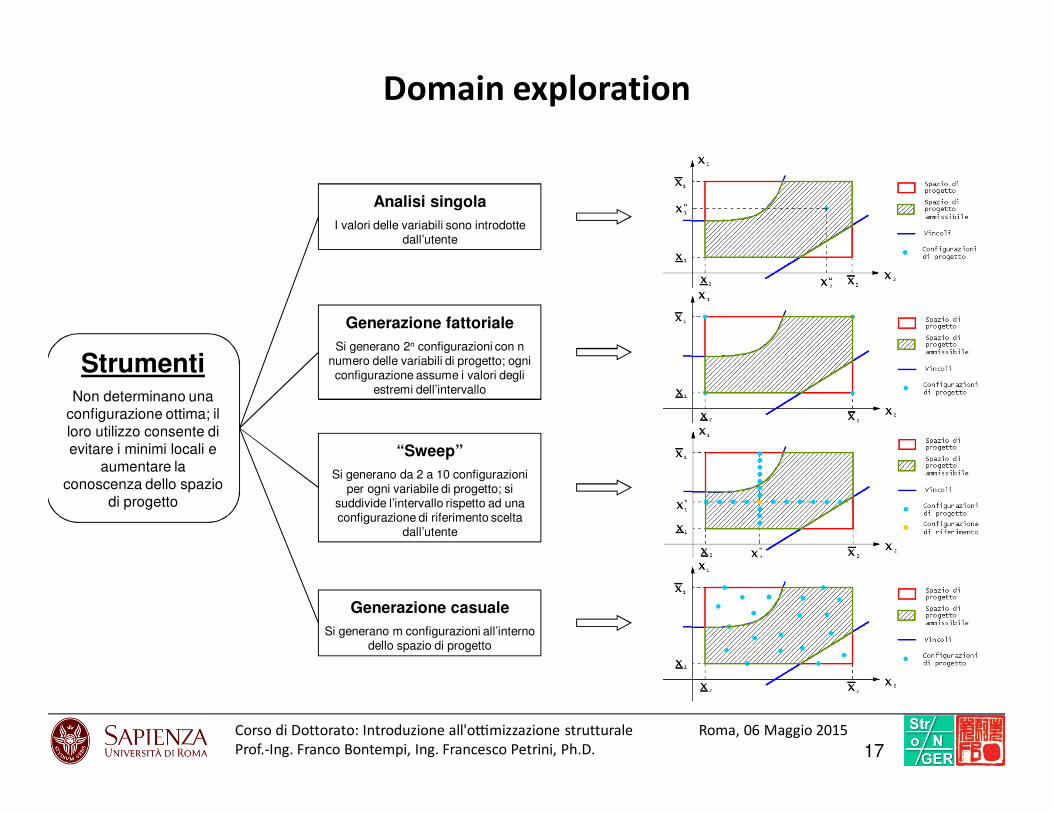
StrumentiNon determinano una
configurazione ottima; il loro utilizzo consente di evitare i minimi locali e
aumentare la conoscenza dello spazio
di progetto
Analisi singola
I valori delle variabili sono introdotte dall’utente
Generazione fattoriale
Si generano 2n configurazioni con n numero delle variabili di progetto; ogni configurazione assume i valori degli
estremi dell’intervallo
“Sweep”
Si generano da 2 a 10 configurazioni per ogni variabile di progetto; si
suddivide l’intervallo rispetto ad una configurazione di riferimento scelta
dall’utente
Generazione casuale
Si generano m configurazioni all’interno dello spazio di progetto
Domain exploration
17Corso di Dottorato: Introduzio ne all'o7mi zzazione struttural e Roma, 06 Maggio 2015
Prof.-Ing. Franco Bontempi, Ing. Francesco Petrini, Ph.D.

Optimization issues in complex systems
18FP
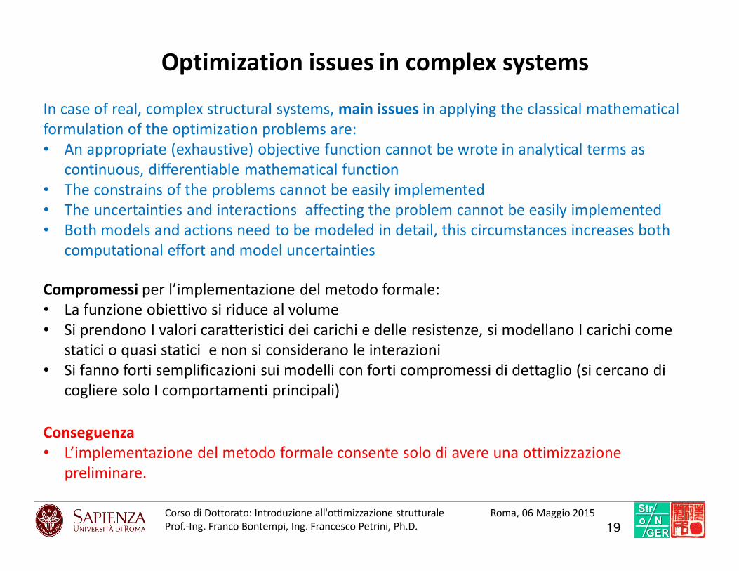
In case of real, complex structural systems, main issues in applying the classical mathematical
formulation of the optimization problems are:
• An appropriate (exhaustive) objective function cannot be wrote in analytical terms as
continuous, differentiable mathematical function
• The constrains of the problems cannot be easily implemented
• The uncertainties and interactions affecting the problem cannot be easily implemented
• Both models and actions need to be modeled in detail, this circumstances increases both
computational effort and model uncertainties
Compromessi per l’implementazione del metodo formale:
• La funzione obiettivo si riduce al volume
• Si prendono I valori caratteristici dei carichi e delle resistenze, si modellano I carichi come
statici o quasi statici e non si considerano le interazioni
• Si fanno forti semplificazioni sui modelli con forti compromessi di dettaglio (si cercano di
cogliere solo I comportamenti principali)
Conseguenza
• L’implementazione del metodo formale consente solo di avere una ottimizzazione
preliminare.
19Corso di Dottorato: Introduzio ne all'o7mi zzazione struttural e Roma, 06 Maggio 2015
Prof.-Ing. Franco Bontempi, Ing. Francesco Petrini, Ph.D.
Optimization issues in complex systems
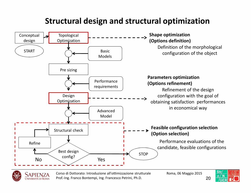
Structural design and structural optimization
Topological
Optimization
Design
Optimization
No
Structural check
Best design
config?
Refine
STOP
Pre sizing
Performance
requirements
Advanced
Model
Basic
Models
Conceptual
design
START
Refinement of the design
configuration with the goal of
obtaining satisfaction performances
in economical way
Shape optimization
(Options definition)
Parameters optimization
(Options refinement)
Feasible configuration selection
(Option selection)
Yes
Definition of the morphological
configuration of the object
Performance evaluations of the
candidate, feasible configurations
20Corso di Dottorato: Introduzio ne all'o7mi zzazione struttural e Roma, 06 Maggio 2015
Prof.-Ing. Franco Bontempi, Ing. Francesco Petrini, Ph.D.
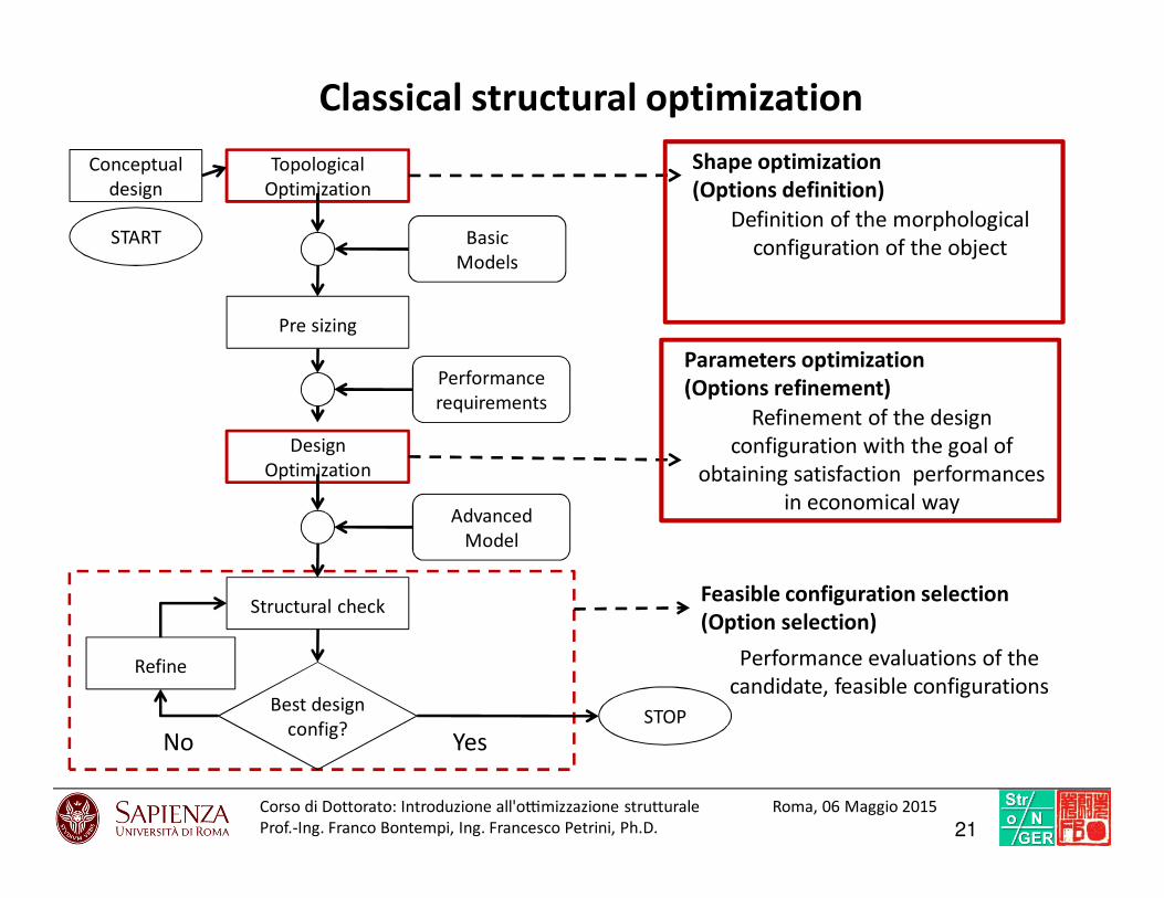
Classical structural optimization
Topological
Optimization
Design
Optimization
No
Structural check
Best design
config?
Refine
STOP
Pre sizing
Performance
requirements
Advanced
Model
Basic
Models
Conceptual
design
START
Refinement of the design
configuration with the goal of
obtaining satisfaction performances
in economical way
Shape optimization
(Options definition)
Parameters optimization
(Options refinement)
Feasible configuration selection
(Option selection)
Yes
Definition of the morphological
configuration of the object
Performance evaluations of the
candidate, feasible configurations
21Corso di Dottorato: Introduzio ne all'o7mi zzazione struttural e Roma, 06 Maggio 2015
Prof.-Ing. Franco Bontempi, Ing. Francesco Petrini, Ph.D.

Final design optimization by PBD
Topological
Optimization
Design
Optimization
PBD
No
Structural check
Best design
config?
Refine
STOP
Pre sizing
Performance
requirements
Advanced
Model
Basic
Models
Conceptual
design
START
Refinement of the design
configuration with the goal of
obtaining satisfaction performances
in economical way
Shape optimization
(Options definition)
Parameters optimization
(Options refinement)
Feasible configuration selection
(Option selection)
Yes
Definition of the morphological
configuration of the object
Performance evaluations of the
candidate, feasible configurations
22Corso di Dottorato: Introduzio ne all'o7mi zzazione struttural e Roma, 06 Maggio 2015
Prof.-Ing. Franco Bontempi, Ing. Francesco Petrini, Ph.D.

Performance-Based Design (PBD)
23FP
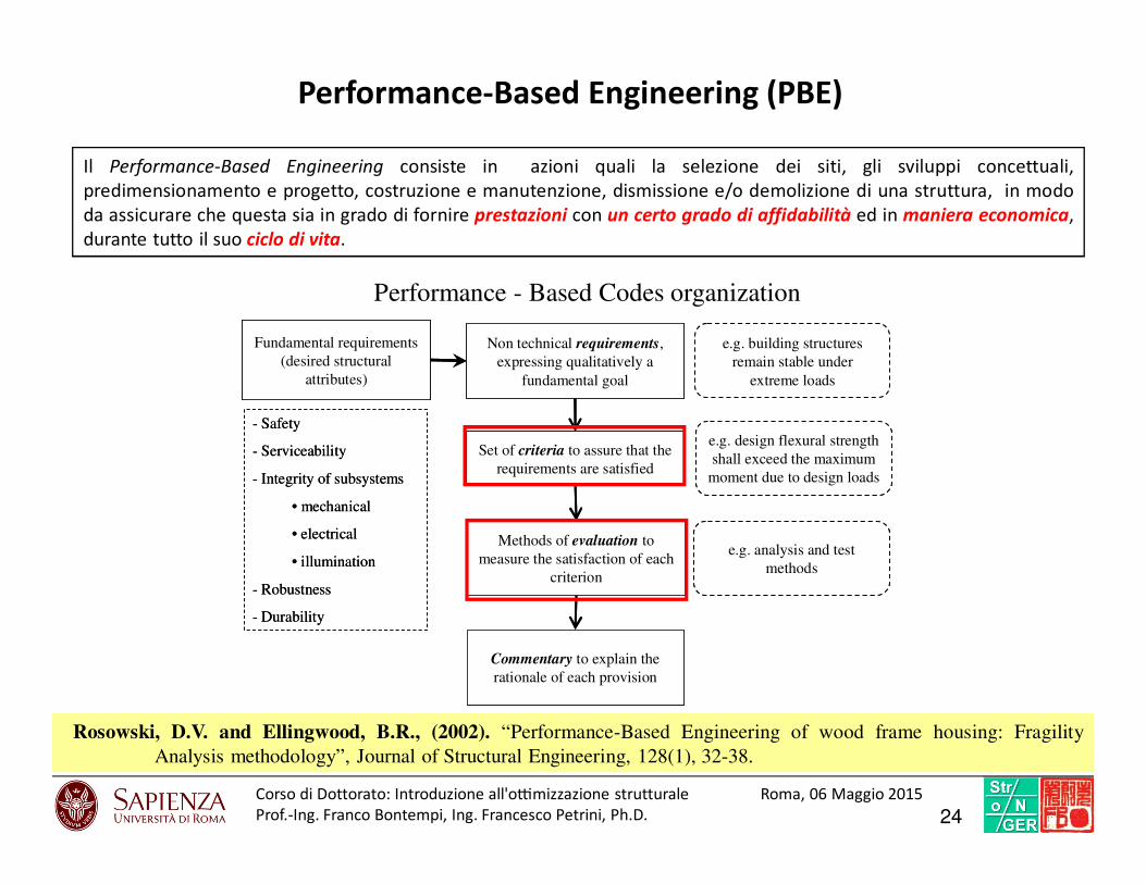
Fundamental requirements
(desired structural
attributes)
Non technical requirements,
expressing qualitatively a
fundamental goal
Set of criteria to assure that the
requirements are satisfied
Methods of evaluation to
measure the satisfaction of each
criterion
Commentary to explain the
rationale of each provision
- Safety
- Serviceability
- Integrity of subsystems
• mechanical
• electrical
• illumination
- Robustness
- Durability
e.g. building structures
remain stable under
extreme loads
e.g. design flexural strength
shall exceed the maximum
moment due to design loads
e.g. analysis and test
methods
Il Performance-Based Engineering consiste in azioni quali la selezione dei siti, gli sviluppi concettuali,
predimensionamento e progetto, costruzione e manutenzione, dismissione e/o demolizione di una struttura, in modo
da assicurare che questa sia in grado di fornire prestazioni con un certo grado di affidabilità ed in maniera economica,
durante tutto il suo ciclo di vita.
Performance-Based Engineering (PBE)
Performance - Based Codes organization
Rosowski, D.V. and Ellingwood, B.R., (2002). “Performance-Based Engineering of wood frame housing: Fragility
Analysis methodology”, Journal of Structural Engineering, 128(1), 32-38.
24Corso di Dottorato: Introduzio ne all'o7mi zzazione struttural e Roma, 06 Maggio 2015
Prof.-Ing. Franco Bontempi, Ing. Francesco Petrini, Ph.D.

Probabilistic approach to PBE
)θq( PDFs uncertain parameters
dRθ∈ Uncertain parameters vector
Mathematical models: θ( )θh
Probability Integral
θ)dθ)q(θh()]θE[h(J ∫==Expected value
( )θh
( )
θ)dθ)q(θ(Iθd)θq(P(F)Jd
R
F
θg
∫∫ ===≤0
Failure
Probability
= Stochastic = Deterministic
Failure
Failure
threshold
Input Output
(response r)
)q(θ1
1θ)q(θ2
2θ
P(M1)
P(M2)
P(Mk)
)q(r1
1r
b =
)q(r2
2r
nθ
),θq(θ mn
mθ
SYSTEM
Input Output
(response r)
)q(θ1
1θ)q(θ2
2θ
P(M1)
P(M2)
P(Mk)
)q(r1
1r
b =
)q(r2
2r
)q(r2
2r
nθ
),θq(θ mn
mθ
nθ
),θq(θ mn
mθ
SYSTEM
( ) ( )( )( )
∈
∉==
θg if θ
θg if θθIθh F
1
0
Failure domain( )θg
1)(1
=∑=
k
i
iMP
Der Kiureghian, A., (2008). “Analysis of structural reliability under parameter uncertainties”, Probabilistic Engineering
Mechanics, 23, 351-358.
25Corso di Dottorato: Introduzio ne all'o7mi zzazione struttural e Roma, 06 Maggio 2015
Prof.-Ing. Franco Bontempi, Ing. Francesco Petrini, Ph.D.
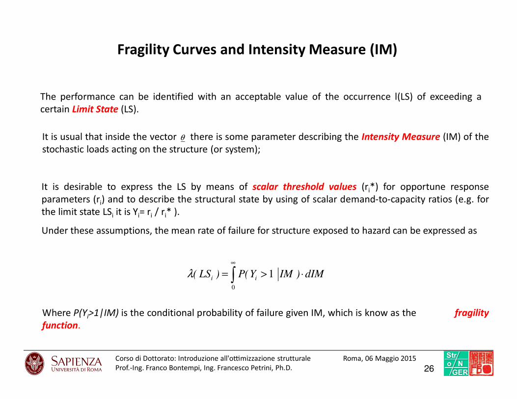
Fragility Curves and Intensity Measure (IM)
It is usual that inside the vector there is some parameter describing the Intensity Measure (IM) of the
stochastic loads acting on the structure (or system);
θ
∫∞
⋅>=0
1 dIM)IMY(P)LS( iiλ
It is desirable to express the LS by means of scalar threshold values (ri*) for opportune response
parameters (ri) and to describe the structural state by using of scalar demand-to-capacity ratios (e.g. for
the limit state LSi it is Yi= ri / ri* ).
Under these assumptions, the mean rate of failure for structure exposed to hazard can be expressed as
Where P(Yi>1|IM) is the conditional probability of failure given IM, which is know as the fragility
function.
The performance can be identified with an acceptable value of the occurrence l(LS) of exceeding a
certain Limit State (LS).
26Corso di Dottorato: Introduzio ne all'o7mi zzazione struttural e Roma, 06 Maggio 2015
Prof.-Ing. Franco Bontempi, Ing. Francesco Petrini, Ph.D.

Performance-Based Earthquake Engineering (PBEE)
2007 2008
27Corso di Dottorato: Introduzio ne all'o7mi zzazione struttural e Roma, 06 Maggio 2015
Prof.-Ing. Franco Bontempi, Ing. Francesco Petrini, Ph.D.

State of the art
dIMIMEDPEDPPLS ∫+∞
⋅>=0
)*()(λ)( IMEDPPfunctionfragility =
EDP
IM
Aug
usti
,G
.,C
iam
pol
i,M
.,(2
008)
,“P
erfo
rmance
-Bas
edD
esig
nin
risk
asse
ssm
ent
and
reduct
ion”,
Pro
bab
ilis
tic
Engin
eeri
ng
Mec
han
ics,
23
,4
96-5
08
Jala
yer,
F.,F
ranc
hin,
P.an
dP
into
,P.E
.(20
07).
“A
scala
rdam
age
mea
sure
for
seis
mic
reli
abil
ity
analy
sis
of
RC
fram
es”,
Ear
thq
uake
Eng
ng.
and
Str
uct.
Dyn.,
36:
2059-2
079.
28Corso di Dottorato: Introduzio ne all'o7mi zzazione struttural e Roma, 06 Maggio 2015
Prof.-Ing. Franco Bontempi, Ing. Francesco Petrini, Ph.D.

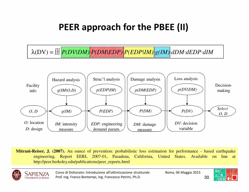
λ(DV) = ∫∫∫ P(DV|DM)·P(DM|EDP)·P(EDP|IM)·g(IM)·dDM·dEDP·dIM
P(x|y) conditional probability of x with respect to y
g(IM*) occurrence IM*
IM Environmental action magnitude (Intensity Measure)
EDP Engineering Demand Parameter describing the response
DM Damage Measure (components condition in terms of functionality requirements)
DV Decision Variable, it is representative of the structural performance
1. Hazard analysis g(IM)
2. Structural analysis P(EDP|IM)
3. Damage analysis P(DM|EDP)
4. Loss analysis P(DV|DM)
Risk
analysis
PEER approach for the PBEE (I)
Identifying the performance with an acceptable value of the occurrence l(DV) of exceeding a threshold
value DV.
29Corso di Dottorato: Introduzio ne all'o7mi zzazione struttural e Roma, 06 Maggio 2015
Prof.-Ing. Franco Bontempi, Ing. Francesco Petrini, Ph.D.
O, D
g(IM|O,D)
g(IM)
p(EDP|IM)
P(EDP)
p(DM|EDP)
P(DM)
p(DV|DM)
P(DV)
Hazard analysis Struc’l analysis Damage analysis Loss analysis
IM: intensity
measure
EDP: engineering
demand param.DM: damage
measure
DV: decision
variable
Select
O, D
O: location
D: design
Facility
info
Decision-
making
λ(DV) = ∫∫∫ P(DV|DM)·P(DM|EDP)·P(EDP|IM)·g(IM)·dDM·dEDP·dIM
PEER approach for the PBEE (II)
Mitrani-Reiser, J. (2007). An ounce of prevention: probabilistic loss estimation for performance - based earthquake
engineering, Report EERL 2007-01, Pasadena, California, United States. Available on line at
http://peer.berkeley.edu/publications/peer_reports.html
30Corso di Dottorato: Introduzio ne all'o7mi zzazione struttural e Roma, 06 Maggio 2015
Prof.-Ing. Franco Bontempi, Ing. Francesco Petrini, Ph.D.

Structural design and structural optimization
Topological
Optimization
Design
Optimization
PBD
No
Structural check
Best design
config?
Refine
STOP
Pre sizing
Performance
requirements
Advanced
Model
Basic
Models
Conceptual
design
START
Feasible configuration selection
(Option selection)
Yes
Performance evaluations of the
candidate, feasible configurations
By focusing on a specific performance
requirement
Investigation on what is the best
configuration
Volume, and weight are checked but not
optimized
Probabilistic Deterministic
31Corso di Dottorato: Introduzio ne all'o7mi zzazione struttural e Roma, 06 Maggio 2015
Prof.-Ing. Franco Bontempi, Ing. Francesco Petrini, Ph.D.
OPTIMIZATION OF THE SUPPORT STRUCTURE
OF OFFSHORE WIND TURBINES• System design approach for complex structural systems optimization
• Substructure typology selection
• Parametric optimization
32FB
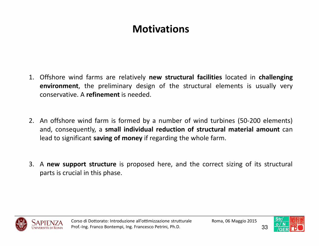
Motivations
1. Offshore wind farms are relatively new structural facilities located in challenging
environment, the preliminary design of the structural elements is usually very
conservative. A refinement is needed.
2. An offshore wind farm is formed by a number of wind turbines (50-200 elements)
and, consequently, a small individual reduction of structural material amount can
lead to significant saving of money if regarding the whole farm.
3. A new support structure is proposed here, and the correct sizing of its structural
parts is crucial in this phase.
33Corso di Dottorato: Introduzio ne all'o7mi zzazione struttural e Roma, 06 Maggio 2015
Prof.-Ing. Franco Bontempi, Ing. Francesco Petrini, Ph.D.
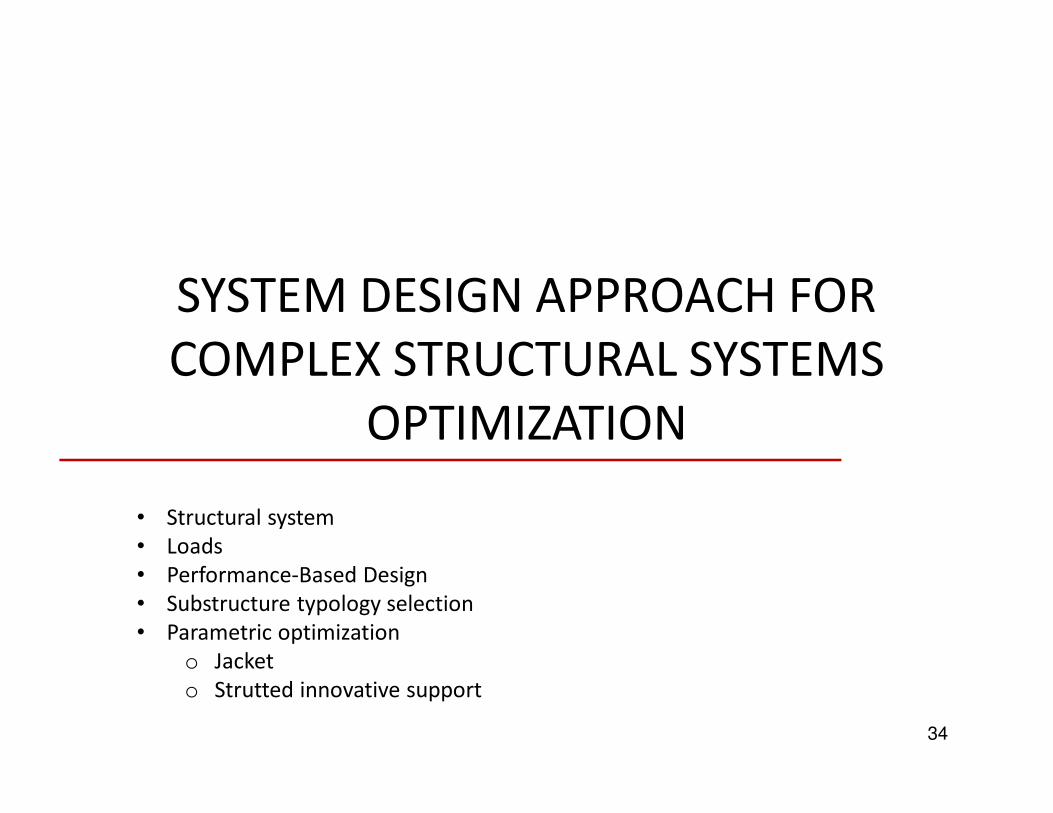
SYSTEM DESIGN APPROACH FOR
COMPLEX STRUCTURAL SYSTEMS
OPTIMIZATION
34
• Structural system
• Loads
• Performance-Based Design
• Substructure typology selection
• Parametric optimization
o Jacket
o Strutted innovative support
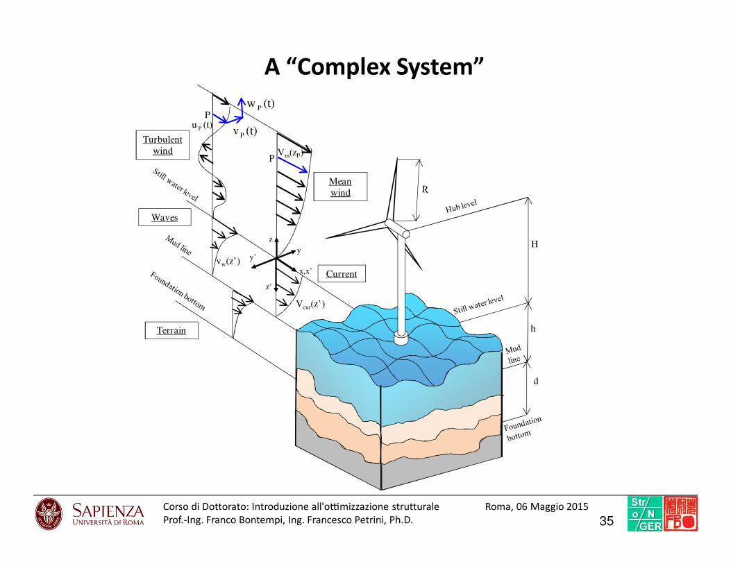
A “Complex System”
x,x’
z’
y’
Waves
Current
P
(t)v P
(t)w P
(t)u P
Turbulent
windP
Mean
wind
Vm(zP)
z
yH
h
vw(z’)
Vcur(z’)
d
Terrain
35Corso di Dottorato: Introduzio ne all'o7mi zzazione struttural e Roma, 06 Maggio 2015
Prof.-Ing. Franco Bontempi, Ing. Francesco Petrini, Ph.D.

NonLinearities
Uncertainty
Interactions
A “Complex System”
36Corso di Dottorato: Introduzio ne all'o7mi zzazione struttural e Roma, 06 Maggio 2015
Prof.-Ing. Franco Bontempi, Ing. Francesco Petrini, Ph.D.
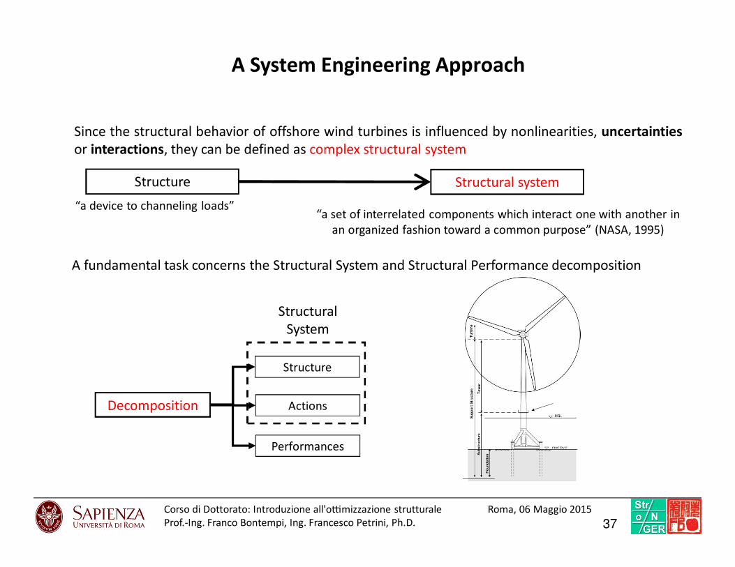
A System Engineering Approach
Since the structural behavior of offshore wind turbines is influenced by nonlinearities, uncertainties
or interactions, they can be defined as complex structural system
“a set of interrelated components which interact one with another in
an organized fashion toward a common purpose” (NASA, 1995)
Structure Structural system
“a device to channeling loads”
Decomposition
Structure
Actions
Performances
Structural
System
A fundamental task concerns the Structural System and Structural Performance decomposition
37Corso di Dottorato: Introduzio ne all'o7mi zzazione struttural e Roma, 06 Maggio 2015
Prof.-Ing. Franco Bontempi, Ing. Francesco Petrini, Ph.D.

Structural system
38FP
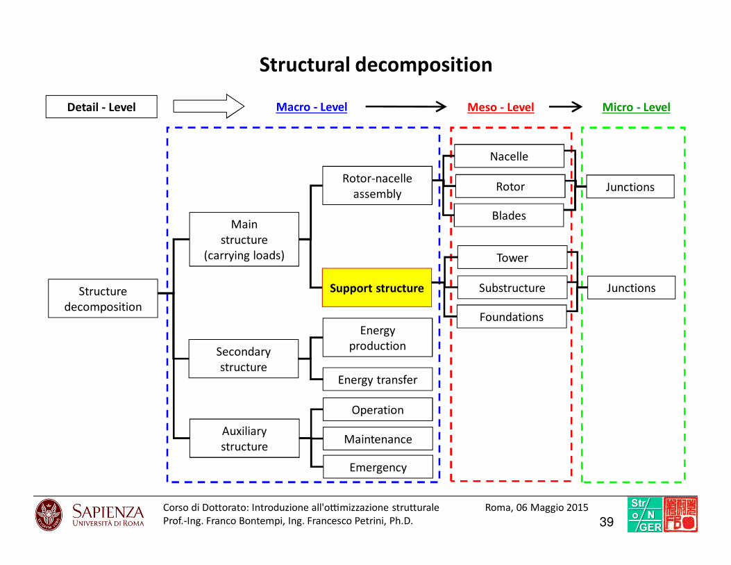
Structural decomposition
Macro - LevelDetail - Level
Structure
decomposition
Main
structure
(carrying loads)
Secondary
structure
Auxiliary
structure
Rotor-nacelle
assembly
Support structure
Energy
production
Energy transfer
Operation
Maintenance
Emergency
Substructure
Tower
Rotor
Nacelle
Blades
Foundations
Meso - Level
Junctions
Junctions
Micro - Level
39Corso di Dottorato: Introduzio ne all'o7mi zzazione struttural e Roma, 06 Maggio 2015
Prof.-Ing. Franco Bontempi, Ing. Francesco Petrini, Ph.D.
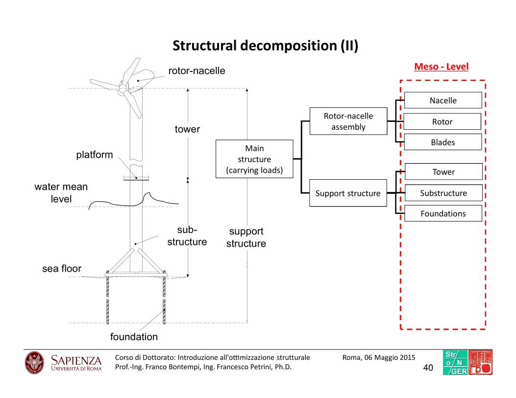
Structural decomposition (II)
platform
tower
support
structure
rotor-nacelle
foundation
sea floor
water mean
level
sub-
structure
Meso - Level
Main
structure
(carrying loads)
Substructure
Tower
Rotor
Nacelle
Blades
Foundations
Rotor-nacelle
assembly
Support structure
40Corso di Dottorato: Introduzio ne all'o7mi zzazione struttural e Roma, 06 Maggio 2015
Prof.-Ing. Franco Bontempi, Ing. Francesco Petrini, Ph.D.

Loads
41FP
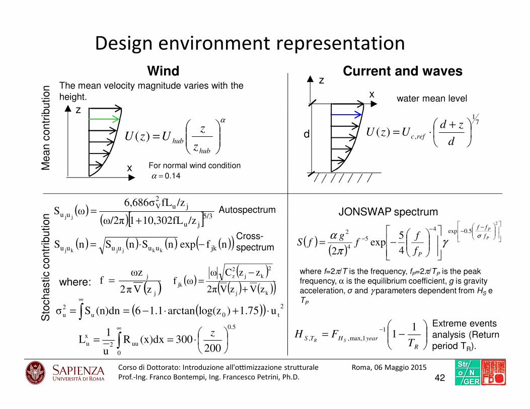
( ) ( ) ( ) ( )( )nfexpnSnSnS jkuuuuuu kkjjkj−⋅=
( )( ) 2
t0
0
u
2
u u1.75)log(zarctan1.16(n)dnSσ ⋅+⋅−== ∫∞
5.0
0
uu2
x
u200
300(x)dxRu
1L
⋅== ∫
∞z
x
z
The mean velocity magnitude varies with the
height.
Mean c
ontr
ibution
Sto
chastic c
ontr
ibution ( )
( )[ ]5/3ju
ju2V
uu/z10,302fL1ω/2π
/zfL6,686σωS
jj +=
( )j
j
zV2π
ωzf = ( )
( )( ) ( )( )kj
2
kj
2
z
jkzVzV2π
zzCωωf
+
−=
Autospectrum
where:
α
=
hub
hubz
zUzU )(
0.14=αFor normal wind condition
( )( )
−−−
−
−=
2
5.0exp4
5
4
2
4
5exp
2
P
P
f
ff
Pf
ff
gfS
σγ
π
α
where f=2π/T is the frequency, fP=2π/TP is the peak
frequency, α is the equilibrium coefficient, g is gravity
acceleration, σ and γ parameters dependent from HS e
TP
−=
−
R
yearHTST
FHSR
11
1
1max,,,
Extreme events
analysis (Return
period TR).
71
,)(
+⋅=
d
zdUzU refc
x
z
d
water mean level
Wind Current and waves
JONSWAP spectrum
Design environment representation
Cross-
spectrum
42Corso di Dottorato: Introduzio ne all'o7mi zzazione struttural e Roma, 06 Maggio 2015
Prof.-Ing. Franco Bontempi, Ing. Francesco Petrini, Ph.D.
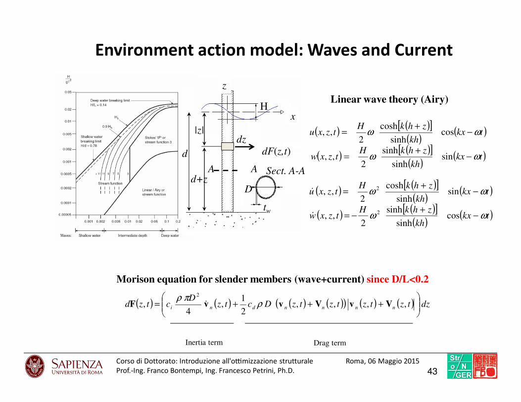
Environment action model: Waves and Current
( ) ( ) ( ) ( )( ) ( ) ( ) dztztztztzDctzD
ctzd nnnndni
+++= ,,,,
2
1,
4,
2
VvVvvF ρπρ
&
Inertia term Drag term
Morison equation for slender members (wave+current) since D/L<0.2
d
|z|
z
x
d+z
dF(z,t)dz
A A Sect. A-A
D
tw
( ) ( )[ ]( )
( )
( ) ( )[ ]( )
( )tkxkh
zhkHtzxw
tkxkh
zhkHtzxu
ωω
ωω
−+
=
−+
=
sinsinh
sinh
2,,
cossinh
cosh
2,,
( ) ( )[ ]( )
( )
( ) ( )[ ]( )
( )tkxkh
zhkHtzxw
tkxkh
zhkHtzxu
ωω
ωω
−+
−=
−+
=
cossinh
sinh
2,,
sinsinh
cosh
2,,
2
2
&
&
Linear wave theory (Airy)H
43Corso di Dottorato: Introduzio ne all'o7mi zzazione struttural e Roma, 06 Maggio 2015
Prof.-Ing. Franco Bontempi, Ing. Francesco Petrini, Ph.D.

Wind force on moving member
( )
( ) RctUCtF
RctUCtF
arelariaDD
arelariaLL
)(2
1),(
)(2
1),(
2
2
ραα
ραα
=
=
2
2
1UACF airaeroD ρ=
Wind force on the tower
φφ cossin LDx FFF +=
ac
R
Picture from:
Hau Erich, Wind Turbines: Fundamentals, technologies, Application,
Economics, 2nd edition. Springer-Verlag Berlin Heidelberg 2006.
xF
αc
Vortex Shedding displacements (across wind)
( )[ ]ct
across
SSD
r
⋅⋅⋅+=
2
max 243.01
29.1
π
2
4
D
mSc
⋅
⋅⋅=
ρ
υπ
Wind actions
44Corso di Dottorato: Introduzio ne all'o7mi zzazione struttural e Roma, 06 Maggio 2015
Prof.-Ing. Franco Bontempi, Ing. Francesco Petrini, Ph.D.
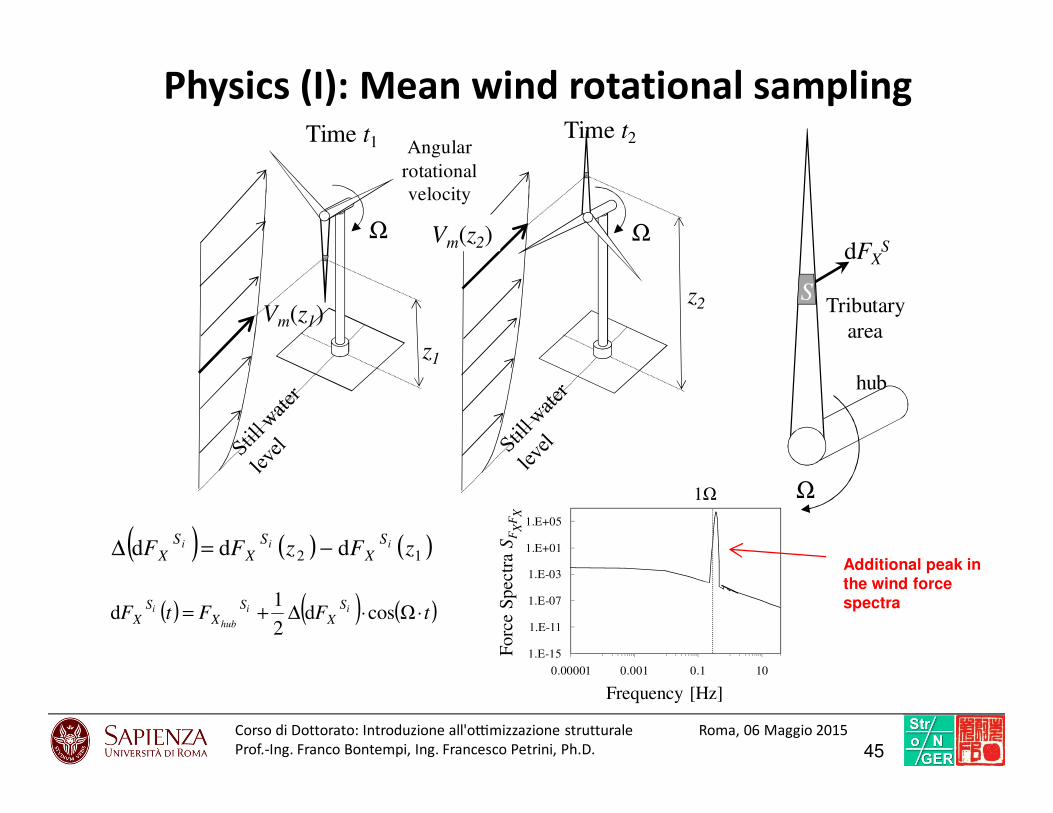
Physics (I): Mean wind rotational sampling
( ) ( ) ( )12 ddd zFzFF iii S
X
S
X
S
X −=∆
z1
Ω
z2
Ω
Time t2Time t1
Vm(z1)
Vm(z2)
Tributary
area
S
Ω
dFXS
Angular
rotational
velocity
hub
( ) ( ) ( )tFFtF ii
hub
i SX
SX
SX ⋅⋅∆+= Ωcosd
2
1d
Additional peak in the wind force spectra
1.E-15
1.E-11
1.E-07
1.E-03
1.E+01
1.E+05
0.00001 0.001 0.1 10
Frequency [Hz]
Forc
e S
pec
tra
SF
XF
X
1Ω
45Corso di Dottorato: Introduzio ne all'o7mi zzazione struttural e Roma, 06 Maggio 2015
Prof.-Ing. Franco Bontempi, Ing. Francesco Petrini, Ph.D.

Processo stocastico
m-dimensionale (mD)
n-variato (nV)
Il processo dipende da m parametri
deterministici
Il processo è costituito da un vettore di n
componenti (processi stocastici
monovariati) tra i quali è possibile definire
densità di probabilità congiunte
Stazionarietà: di ordine j, se le statistiche
sugli insiemi fino all’ordine j-esimo sono
costanti nel tempo
Ergodicittà: se i momenti stocastici del
processo coincidono con quelli della singola
realizzazione
Gaussianità: si i momenti stocastici di ordine
superiore al secondo sono nulli
1D – 1V
[ ] ∫ ∫ ∫+∞
∞−
+∞
∞−
+∞
∞−
=ssXss
dxdxdxxpxxxXXXEs
...)(.......... 212121
ρβαρβα
Momento stocastico di ordine j
ρβα +++= ...j
Wind turbulent component characteristics (I)
46Corso di Dottorato: Introduzio ne all'o7mi zzazione struttural e Roma, 06 Maggio 2015
Prof.-Ing. Franco Bontempi, Ing. Francesco Petrini, Ph.D.
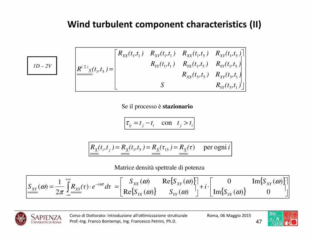
1D – 2V
=
),t(tRS
),t(tR),t(tR
),t(tR),t(tR),t(tR
),t(tR),t(tR),t(tR),t(tR
),t(tR
YY
XYXX
YYYXYY
XYXXXYXX
X)(
15
1555
515111
51511111
51
2
ijijijtttt >−= con τ
i(τR)(τR),t(tR),t(tR XXXjiX ogniper )1551 ===
Se il processo è stazionario
⋅+
=⋅= ∫
+∞
∞
−
0)(Im
)(Im0
)()(Re
)(Re)( )
2
1)(
-ω
ω
ωω
ωω
πω ωτ
YX
XY
YYYX
XYXXi
XYXYS
Si
SS
SSdτe(τRS
Matrice densità spettrale di potenza
Wind turbulent component characteristics (II)
47Corso di Dottorato: Introduzio ne all'o7mi zzazione struttural e Roma, 06 Maggio 2015
Prof.-Ing. Franco Bontempi, Ing. Francesco Petrini, Ph.D.

Physics (II): Turbulent wind rotational sampling
Variation of the turbulent force spectra with the blade position during its rotational
motion
Halfpenny A. (1988). Dynamic Analysis of Both On and Offshore Wind Turbines in the Frequency Domain. Ph.D. thesis.
University College London..
Connell J.R. (1988). “A PRIMER OF TURBULENCE AT THE WIND TURBINE ROTOR”, Solar Energy, 41 (3), 281-293
The wind forces acing on the Beam Element (BE) implies two different contributions:
i) the fluctuating component due to the variation of mean wind experimented by the BE at different height
during its rotational motion, and
ii) the so called “rotational sampled turbulent wind”, that is the stochastic contribution due to the incoming
wind turbulence experimented by the rotating BE
48Corso di Dottorato: Introduzio ne all'o7mi zzazione struttural e Roma, 06 Maggio 2015
Prof.-Ing. Franco Bontempi, Ing. Francesco Petrini, Ph.D.
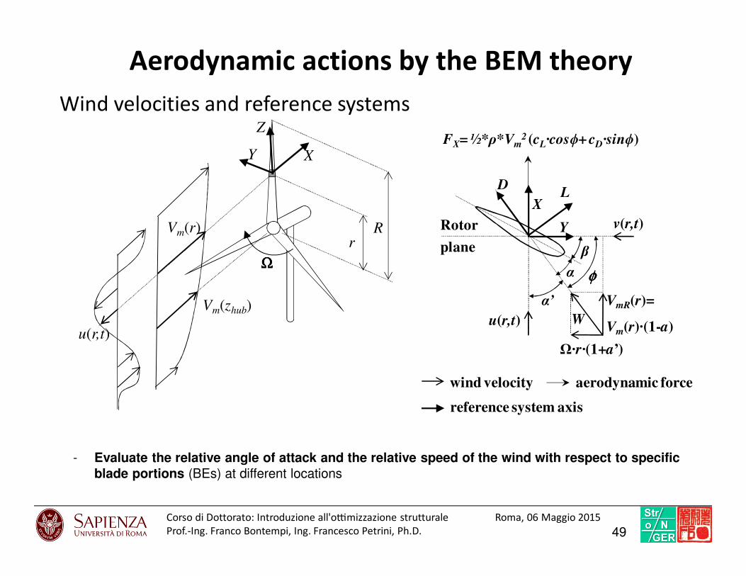
R
ΩΩΩΩ
Vm(r)r
Vm(zhub)
u(r,t)
XY
Z
Aerodynamic actions by the BEM theory
Wind velocities and reference systems
- Evaluate the relative angle of attack and the relative speed of the wind with respect to specific blade portions (BEs) at different locations
Ω·r·(1+a’)
α
Y
X
DL
β
φφφφ
VmR(r)=
Vm(r)·(1-a)W
Rotor
plane
u(r,t)
v(r,t)
α’
FX= ½*ρ*Vm2 (cL·cosϕ+ cD·sinϕ)
aerodynamic force
reference system axis
wind velocity
49Corso di Dottorato: Introduzio ne all'o7mi zzazione struttural e Roma, 06 Maggio 2015
Prof.-Ing. Franco Bontempi, Ing. Francesco Petrini, Ph.D.
ENVIRONMENT
Structure
Non
environmental
solicitations
STRUCTURE
Structural (non-environmental)
system
Site-specific environment
Wind site
basic
parameters
Other
environmental
agents
Waves site
basic
parameters
Wind, wave and current actions
Aerodynamic and Aeroelastic
phenomena
Hydrodynamic phenomena
1. Aleatoric
2. Epistemic
3. Model
Types of uncertainties
1. Aleatoric
2. Epistemic
3. Model
1. Aleatoric
2. Epistemic
3. Model
Propagation Propagation
Interaction
parametersStructural parametersIntensity
Measure
( )IM ( )IP ( )SP
EXCHANGE ZONE
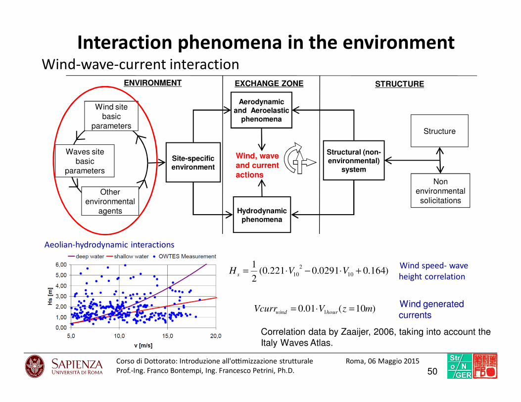
Interaction phenomena in the environmentWind-wave-current interaction
Aeolian-hydrodynamic interactions
)10(01.0 1 mzVVcurr hourwind =⋅=
Wind speed- wave
height correlation
Wind generated
currents
)164.00291.0221.0(2
110
2
10 +⋅−⋅= VVH s
Correlation data by Zaaijer, 2006, taking into account the
Italy Waves Atlas.
50Corso di Dottorato: Introduzio ne all'o7mi zzazione struttural e Roma, 06 Maggio 2015
Prof.-Ing. Franco Bontempi, Ing. Francesco Petrini, Ph.D.
Modeling strategy
51FP
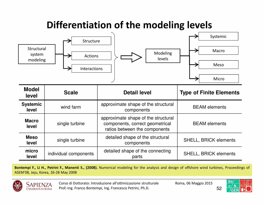
Structural
system
modeling
Structure
Actions
Interactions
Modeling
levels
Systemic
Macro
Meso
Micro
Model level
Scale Detail level Type of Finite Elements
Systemic level
wind farmapproximate shape of the structural
componentsBEAM elements
Macro level
single turbine
approximate shape of the structural
components, correct geometrical
ratios between the components
BEAM elements
Meso level
single turbinedetailed shape of the structural
componentsSHELL, BRICK elements
micro level
individual componentsdetailed shape of the connecting
partsSHELL, BRICK elements
Differentiation of the modeling levels
Bontempi F., Li H., Petrini F., Manenti S., (2008). Numerical modeling for the analysis and design of offshore wind turbines, Proceedings of
ASEM'08, Jeju, Korea, 26-28 May 2008
52Corso di Dottorato: Introduzio ne all'o7mi zzazione struttural e Roma, 06 Maggio 2015
Prof.-Ing. Franco Bontempi, Ing. Francesco Petrini, Ph.D.
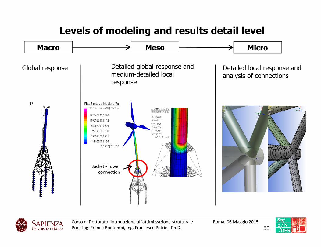
1°1°
Macro
Global response
Meso Micro
Levels of modeling and results detail level
Jacket - Tower
connection
Detailed global response and medium-detailed local response
Detailed local response and analysis of connections
53Corso di Dottorato: Introduzio ne all'o7mi zzazione struttural e Roma, 06 Maggio 2015
Prof.-Ing. Franco Bontempi, Ing. Francesco Petrini, Ph.D.

Substructure typology selection
54FP

Structural design and structural optimization
Topological
Optimization
Design
Optimization
PBD
No
Structural check
Best design
config?
Refine
STOP
Pre sizing
Performance
requirements
Advanced
Model
Basic
Models
Conceptual
design
START
Shape optimization
(Options definition)
Parameters optimization
(Options refinement)
Feasible configuration selection
(Option selection)
Yes
Definition of the morphological
configuration of the object
55Corso di Dottorato: Introduzio ne all'o7mi zzazione struttural e Roma, 06 Maggio 2015
Prof.-Ing. Franco Bontempi, Ing. Francesco Petrini, Ph.D.
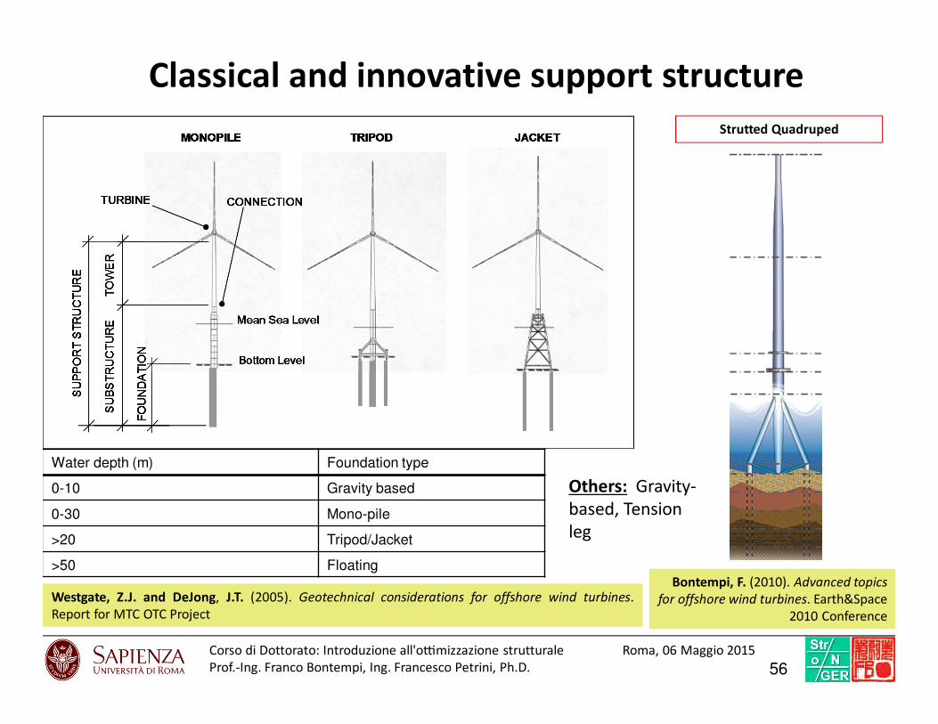
Classical and innovative support structure
Westgate, Z.J. and DeJong, J.T. (2005). Geotechnical considerations for offshore wind turbines.
Report for MTC OTC Project
Water depth (m) Foundation type
0-10 Gravity based
0-30 Mono-pile
>20 Tripod/Jacket
>50 FloatingBontempi, F. (2010). Advanced topics
for offshore wind turbines. Earth&Space
2010 Conference
Strutted Quadruped
Others: Gravity-
based, Tension
leg
56Corso di Dottorato: Introduzio ne all'o7mi zzazione struttural e Roma, 06 Maggio 2015
Prof.-Ing. Franco Bontempi, Ing. Francesco Petrini, Ph.D.

Monopile [m] Tripod [m] Jacket [m]
h a.s.l.=100
d=35
l found=40
D =5
tw=0,05
D found=6
h a.s.l. =100
d =35
l found =40
D =5
tw =0,05
D tripod =2,5
tw tripod =0,05
D found =2,5
h a.s.l. =100
d =35
l found =40
D =5
tw =0,05
Comparison of support structure typologies (Macro-Level models)
z
y x
Wind
Fluid-dynamic
Geotechnical
Foundation
Immersed
Emergent
d
l found
h a.s.l.
z
y x
z
y x
Wind
Fluid-dynamic
Geotechnical
Foundation
Immersed
Emergent
d
l found
h a.s.l.
D = tower diameter
D found =foundation piles diameters
tw= tower tubular thickness
h a.s.l.=100m
d=35m
57Corso di Dottorato: Introduzio ne all'o7mi zzazione struttural e Roma, 06 Maggio 2015
Prof.-Ing. Franco Bontempi, Ing. Francesco Petrini, Ph.D.
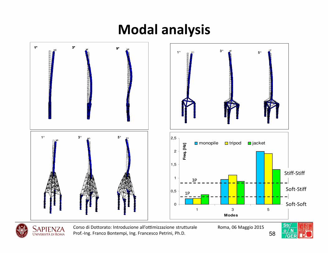
Modal analysis
1° 3°5°1° 3°5°
3° 5°1° 3° 5°1°
0
0,5
1
1,5
2
2,5
1 3 5
Modes
Fre
q. [H
z] monopile tripod jacket
3P
1P
Stiff-Stiff
Soft-Stiff
Soft-Soft
58Corso di Dottorato: Introduzio ne all'o7mi zzazione struttural e Roma, 06 Maggio 2015
Prof.-Ing. Franco Bontempi, Ing. Francesco Petrini, Ph.D.

Static extreme analysis
Wind on the
towerWind on the rotor-
nacelle assemblyCurrent and
wave
Design
Situation
D.L.C.
(GL, 2005)
Wind
Condition
(steady)
Marine
Condition
(regular)
Type of
Analysis
Load Factors γF
Environ. Grav. Inert.
Parked
(standstill or
idling)
6.1b Uhub=Ue100 H=Hred100
Ultimate
strength1.35 1.1 1.25
6.1c Uhub=Ured100 H=Hmax100
Ultimate
strength1.35 1.1 1.25
6.3b Uhub=Ue1 H=Hred100
Ultimate
strength1.35 1.1 1.25
Vento su torre-Monopila
0
20
40
60
80
100
120
0 2000 4000 6000 8000
Azione [N/m]
qu
ota
s.l
.m.
[m]
Comb 6.1b Comb 6.1cLoad Case 6.1b
Load Case 6.1c
Heig
ht
ab
ov
e m
ea
n s
ea
lev
el [m
]
Wind induced drag per unit length [N/m]
Vento su torre-Monopila
0
20
40
60
80
100
120
0 2000 4000 6000 8000
Azione [N/m]
qu
ota
s.l
.m.
[m]
Comb 6.1b Comb 6.1cLoad Case 6.1b
Load Case 6.1c
Heig
ht
ab
ov
e m
ea
n s
ea
lev
el [m
]
Wind induced drag per unit length [N/m]
Drag e Inerzia (corrente+onde)-
Monopila
0
5
10
15
20
25
30
0 20000 40000 60000 80000
Azione [N/m]
qu
ota
su
l fo
nd
ale
[m
]
Comb 6.1b Comb 6.1cLoad Case 6.1c
Heig
ht
ab
ov
e b
ott
om
[m
]
Wave-current induced force per unit length [N/m]
Drag e Inerzia (corrente+onde)-
Monopila
0
5
10
15
20
25
30
0 20000 40000 60000 80000
Azione [N/m]
qu
ota
su
l fo
nd
ale
[m
]
Comb 6.1b Comb 6.1cLoad Case 6.1c
Heig
ht
ab
ov
e b
ott
om
[m
]
Wave-current induced force per unit length [N/m]
59Corso di Dottorato: Introduzio ne all'o7mi zzazione struttural e Roma, 06 Maggio 2015
Prof.-Ing. Franco Bontempi, Ing. Francesco Petrini, Ph.D.

Static extreme analysis – Performances comparison
Reazione totale taglio a terra [ton]
0
100
200
300
400
500
600
700
Monopila Tripode Jacket
6.1b 6.1c 6.3b
Resultant shear stress at the bottom [N]104
104 Momento ribaltante [ton*m]
0
5000
10000
15000
20000
25000
30000
35000
40000
Monopila Tripode Jacket
6.1b 6.1c 6.3bSpostamento navicella [m]
0
0,5
1
1,5
2
2,5
3
3,5
4
4,5
5
Monopila Tripode Jacket
6.1b 6.1c 6.3b
Resultant overturning moment at the bottom [N*m]
Horizontal hub displacement [m]
104
Monopile Tripod Jacket
Combination 6.1b (GL 2005) Monopile Tripod Jacket
Action
Wind on rotor [ton] 166,3
166,3 166,3
Wind on tower [ton] 74
74 42,8
Wave and current [ton] 337,2
337,2 350
Overturning moment [ton*m] 35045,6
35045,6 33708,7
Reactions at mud
line
Shear reaction at mud line [ton] 577,5
577,5 559,1
Vertical reaction at mud line (no piles) [ton]
1071,41035,63
(max/pile=1501,8)
1376,8
(max/pile =992,9)
Structural checks
Maximum stress in the tower [N/mm2]
286230 151
Nacelle displacement [m] 4,66
3,72 1,82
60Corso di Dottorato: Introduzio ne all'o7mi zzazione struttural e Roma, 06 Maggio 2015
Prof.-Ing. Franco Bontempi, Ing. Francesco Petrini, Ph.D.
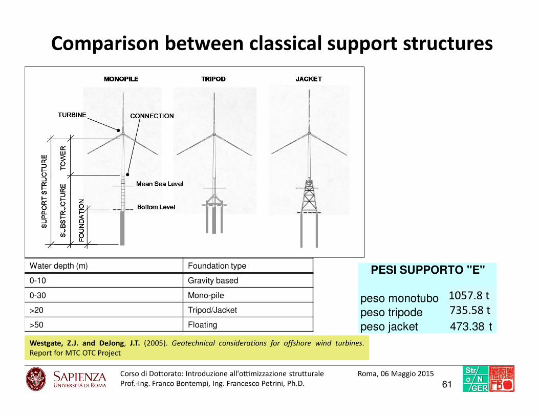
Comparison between classical support structures
Westgate, Z.J. and DeJong, J.T. (2005). Geotechnical considerations for offshore wind turbines.
Report for MTC OTC Project
Water depth (m) Foundation type
0-10 Gravity based
0-30 Mono-pile
>20 Tripod/Jacket
>50 Floating
peso monotubo 205.78 t
peso tripode 635.58 t
peso jacket 473.38 t
PESI SUPPORTO "E"
1057.8 t
735.58 t
61Corso di Dottorato: Introduzio ne all'o7mi zzazione struttural e Roma, 06 Maggio 2015
Prof.-Ing. Franco Bontempi, Ing. Francesco Petrini, Ph.D.

Parametric optimization
62FP

Structural design and structural optimization
Topological
Optimization
Design
Optimization
PBD
No
Structural check
Best design
config?
Refine
STOP
Pre sizing
Performance
requirements
Advanced
Model
Basic
Models
Conceptual
design
START
Refinement of the design
configuration with the goal of
obtaining satisfaction performances
in economical way
Shape optimization
(Options definition)
Parameters optimization
(Options refinement)
Feasible configuration selection
(Option selection)
Yes
63Corso di Dottorato: Introduzio ne all'o7mi zzazione struttural e Roma, 06 Maggio 2015
Prof.-Ing. Franco Bontempi, Ing. Francesco Petrini, Ph.D.

Jacket support
64

GEOMETRIADimensioni in elevazione
Dimensioni in pianta
• Altezza totale: 180 m
• Altezza fuori terra: 140 m
• Altezza sopra il pelo libero: 105 m
65Corso di Dottorato: Introduzio ne all'o7mi zzazione struttural e Roma, 06 Maggio 2015
Prof.-Ing. Franco Bontempi, Ing. Francesco Petrini, Ph.D.
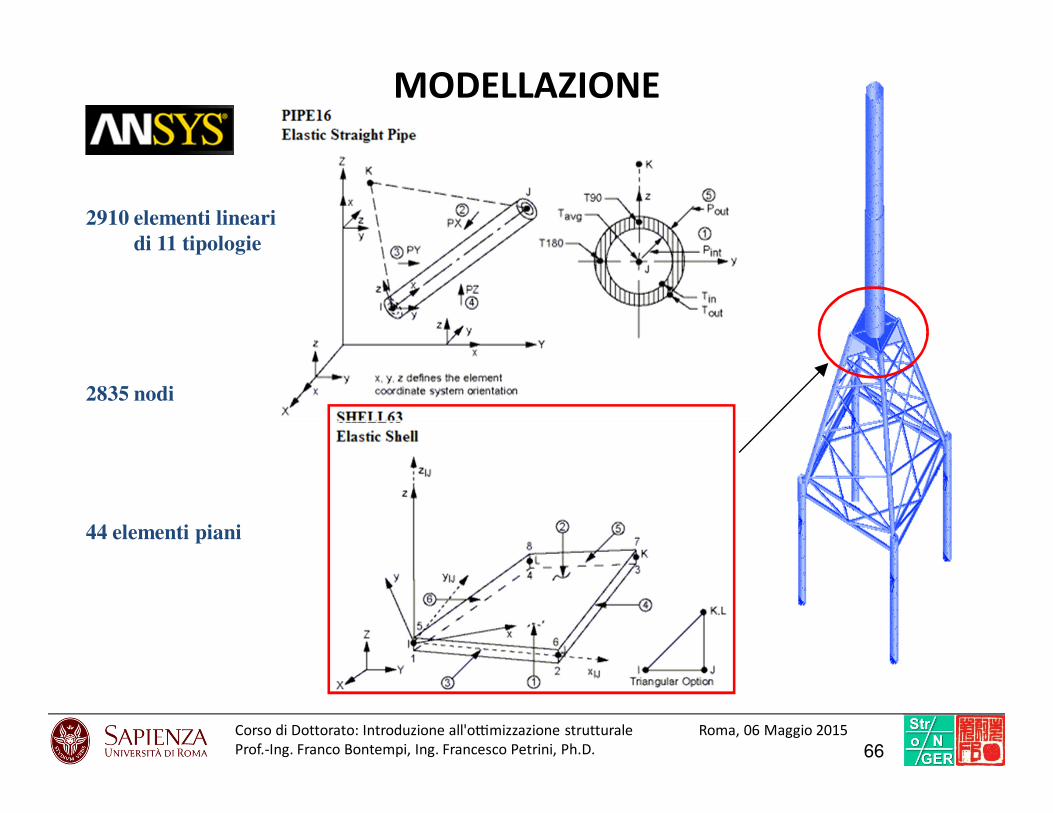
MODELLAZIONE
2835 nodi
2910 elementi linearidi 11 tipologie
44 elementi piani
66Corso di Dottorato: Introduzio ne all'o7mi zzazione struttural e Roma, 06 Maggio 2015
Prof.-Ing. Franco Bontempi, Ing. Francesco Petrini, Ph.D.
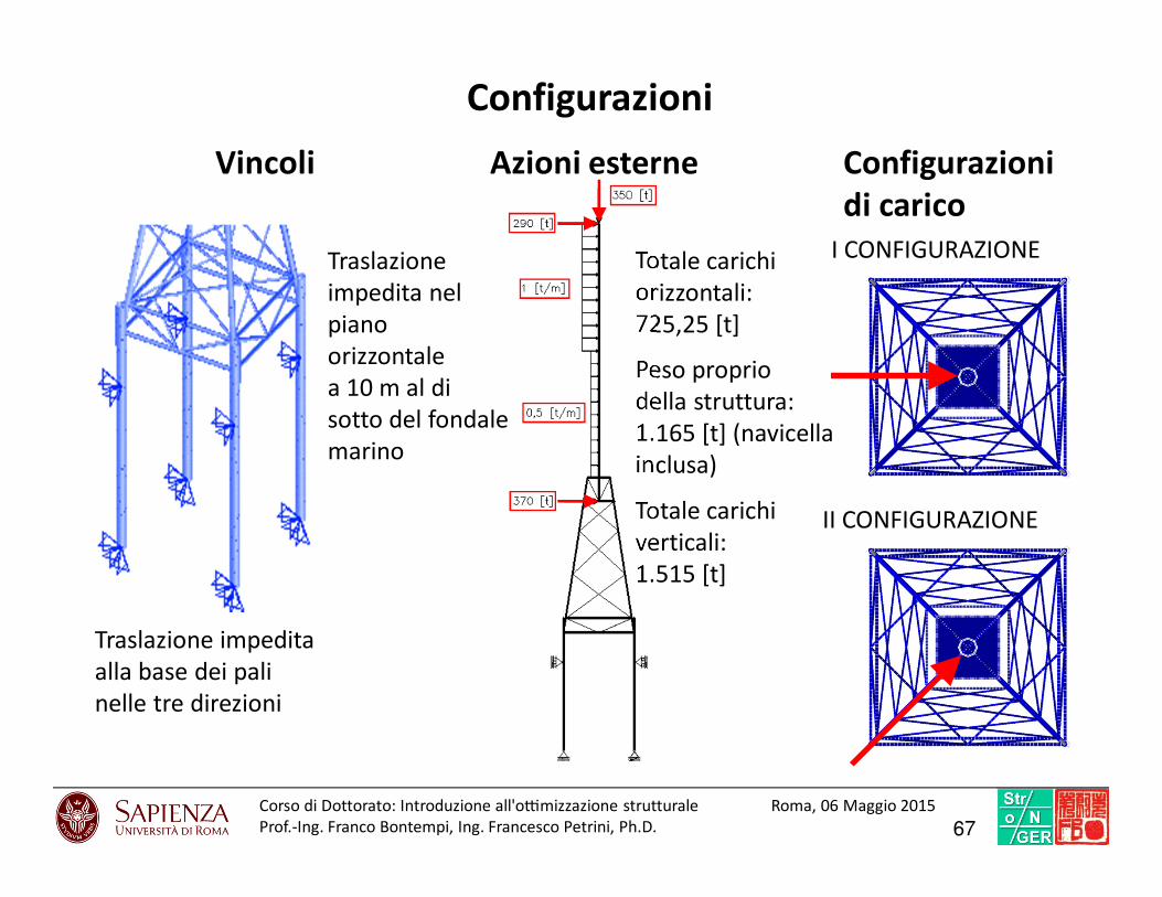
Vincoli
Traslazione impedita
alla base dei pali
nelle tre direzioni
Traslazione
impedita nel
piano
orizzontale
a 10 m al di
sotto del fondale
marino
Azioni esterne
Totale carichi
orizzontali:
725,25 [t]
Peso proprio
della struttura:
1.165 [t] (navicella
inclusa)
Totale carichi
verticali:
1.515 [t]
Configurazioni
di carico
I CONFIGURAZIONE
II CONFIGURAZIONE
Configurazioni
67Corso di Dottorato: Introduzio ne all'o7mi zzazione struttural e Roma, 06 Maggio 2015
Prof.-Ing. Franco Bontempi, Ing. Francesco Petrini, Ph.D.

105 Parametri
42 Potenziali variabili di progetto
8 relative alla “forma” della struttura
34 relative alle sezioni degli elementi
DESIGN OPTIMIZATION (D. O.)
68Corso di Dottorato: Introduzio ne all'o7mi zzazione struttural e Roma, 06 Maggio 2015
Prof.-Ing. Franco Bontempi, Ing. Francesco Petrini, Ph.D.
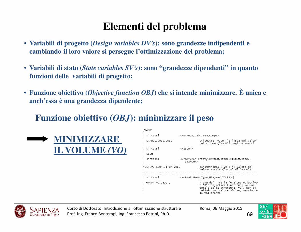
• Variabili di progetto (Design variables DV’s): sono grandezze indipendenti e cambiando il loro valore si persegue l’ottimizzazione del problema;
• Variabili di stato (State variables SV’s): sono “grandezze dipendenti” in quantofunzioni delle variabili di progetto;
Elementi del problema
• Funzione obiettivo (Objective function OBJ) che si intende minimizzare. È unica e anch’essa è una grandezza dipendente;
Funzione obiettivo (OBJ): minimizzare il peso
MINIMIZZARE IL VOLUME (VO)
69Corso di Dottorato: Introduzio ne all'o7mi zzazione struttural e Roma, 06 Maggio 2015
Prof.-Ing. Franco Bontempi, Ing. Francesco Petrini, Ph.D.

MOLTIPLICATORE CARICO CRITICO (BLF) ≥ 2,5
Variabili di stato (SV):
70Corso di Dottorato: Introduzio ne all'o7mi zzazione struttural e Roma, 06 Maggio 2015
Prof.-Ing. Franco Bontempi, Ing. Francesco Petrini, Ph.D.
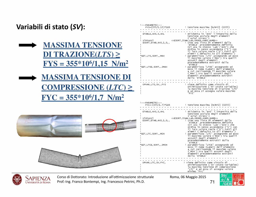
MASSIMA TENSIONEDI TRAZIONE(LTS) ≥FYS = 355*106/1,15 N/m2
MASSIMA TENSIONE DICOMPRESSIONE (LTC) ≥ FYC = 355*106/1,7 N/m2
Variabili di stato (SV):
71Corso di Dottorato: Introduzio ne all'o7mi zzazione struttural e Roma, 06 Maggio 2015
Prof.-Ing. Franco Bontempi, Ing. Francesco Petrini, Ph.D.
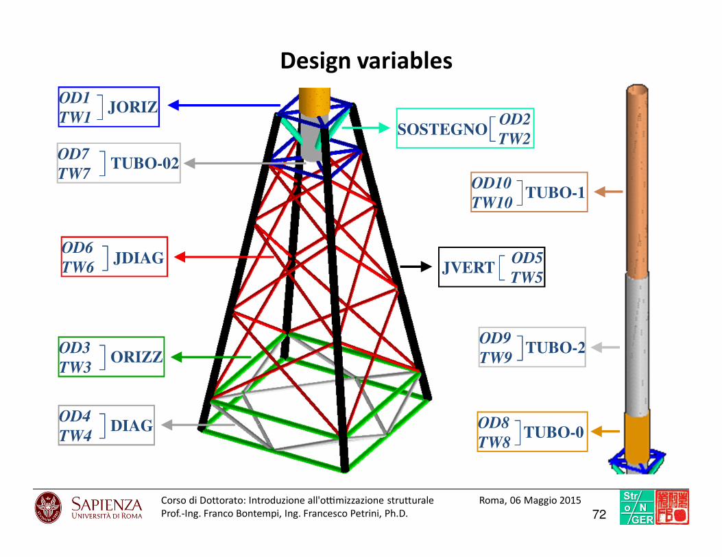
JORIZOD1
TW1]]]]
SOSTEGNO[[[[OD2
TW2
ORIZZ]]]]OD3
TW3
TUBO-02]]]]OD7
TW7
JVERT[[[[ OD5
TW5
JDIAG]]]]OD6
TW6
DIAG]]]]OD4
TW4
TUBO-1]]]]OD10
TW10
TUBO-2]]]]OD9
TW9
TUBO-0]]]]OD8
TW8
Design variables
72Corso di Dottorato: Introduzio ne all'o7mi zzazione struttural e Roma, 06 Maggio 2015
Prof.-Ing. Franco Bontempi, Ing. Francesco Petrini, Ph.D.

Un
de
tect
ed
bu
ckli
ng
Ass
em
bla
ge
co
nst
rain
sAcceptable Unacceptable
Special checks on unconsidered aspects
73Corso di Dottorato: Introduzio ne all'o7mi zzazione struttural e Roma, 06 Maggio 2015
Prof.-Ing. Franco Bontempi, Ing. Francesco Petrini, Ph.D.
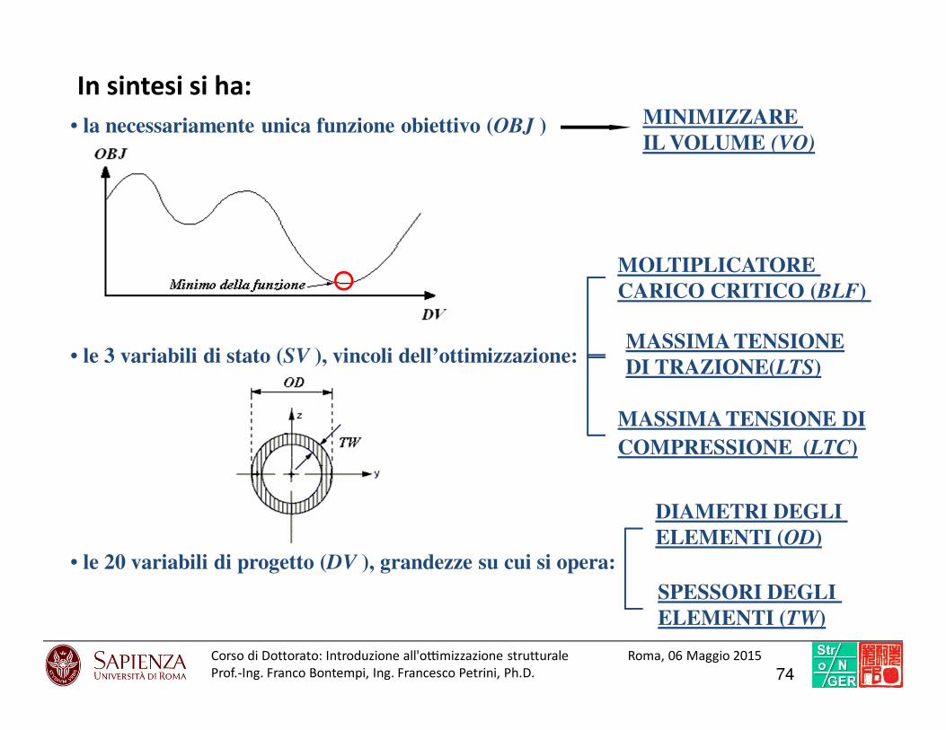
In sintesi si ha:
• la necessariamente unica funzione obiettivo (OBJ ) MINIMIZZARE IL VOLUME (VO)
• le 3 variabili di stato (SV ), vincoli dell’ottimizzazione:[[[[[[[[
MASSIMA TENSIONEDI TRAZIONE(LTS)
MASSIMA TENSIONE DICOMPRESSIONE (LTC)
MOLTIPLICATORE CARICO CRITICO (BLF)
• le 20 variabili di progetto (DV ), grandezze su cui si opera:
DIAMETRI DEGLI ELEMENTI (OD)
[[[[ SPESSORI DEGLI ELEMENTI (TW)
74Corso di Dottorato: Introduzio ne all'o7mi zzazione struttural e Roma, 06 Maggio 2015
Prof.-Ing. Franco Bontempi, Ing. Francesco Petrini, Ph.D.
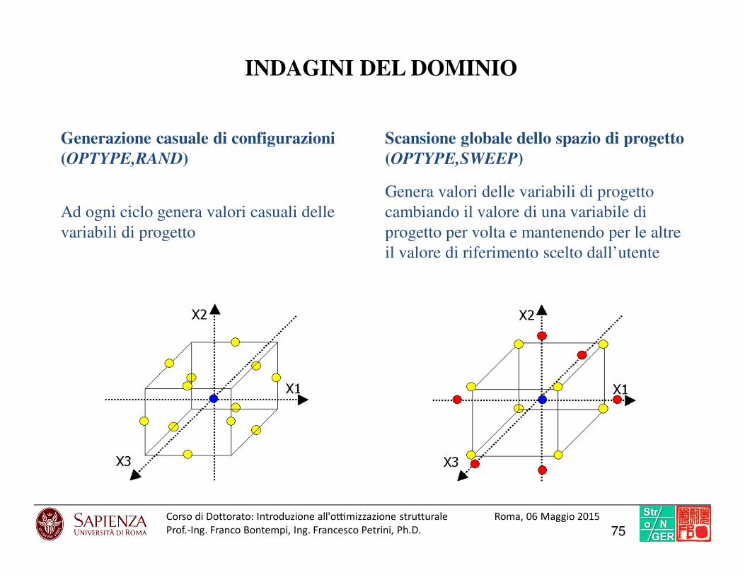
Generazione casuale di configurazioni(OPTYPE,RAND)
INDAGINI DEL DOMINIO
Scansione globale dello spazio di progetto(OPTYPE,SWEEP)
Ad ogni ciclo genera valori casuali delle
variabili di progetto
Genera valori delle variabili di progetto
cambiando il valore di una variabile di
progetto per volta e mantenendo per le altre
il valore di riferimento scelto dall’utente
75Corso di Dottorato: Introduzio ne all'o7mi zzazione struttural e Roma, 06 Maggio 2015
Prof.-Ing. Franco Bontempi, Ing. Francesco Petrini, Ph.D.
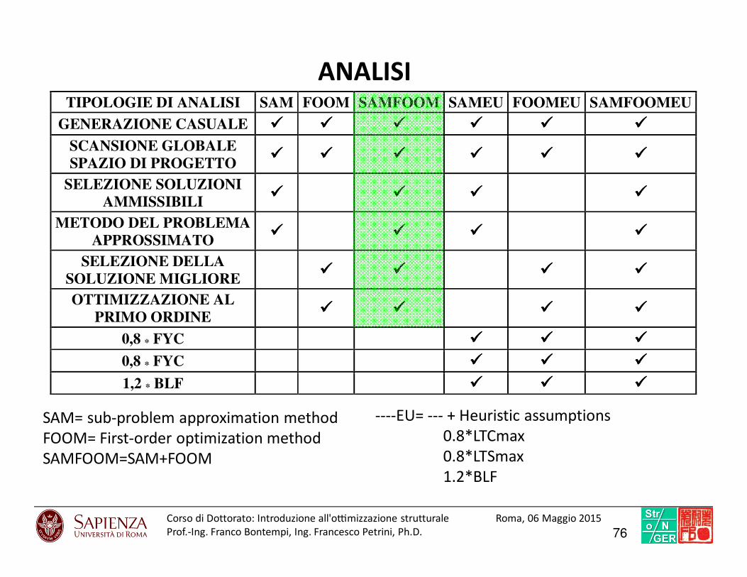
ANALISITIPOLOGIE DI ANALISI SAM FOOM SAMFOOM SAMEU FOOMEU SAMFOOMEU
GENERAZIONE CASUALE
SCANSIONE GLOBALE SPAZIO DI PROGETTO
SELEZIONE SOLUZIONI AMMISSIBILI
METODO DEL PROBLEMA APPROSSIMATO
SELEZIONE DELLA SOLUZIONE MIGLIORE
OTTIMIZZAZIONE AL PRIMO ORDINE
0,8 * FYC
0,8 * FYC
1,2 * BLF
SAM= sub-problem approximation method
FOOM= First-order optimization method
SAMFOOM=SAM+FOOM
----EU= --- + Heuristic assumptions
0.8*LTCmax
0.8*LTSmax
1.2*BLF
76Corso di Dottorato: Introduzio ne all'o7mi zzazione struttural e Roma, 06 Maggio 2015
Prof.-Ing. Franco Bontempi, Ing. Francesco Petrini, Ph.D.
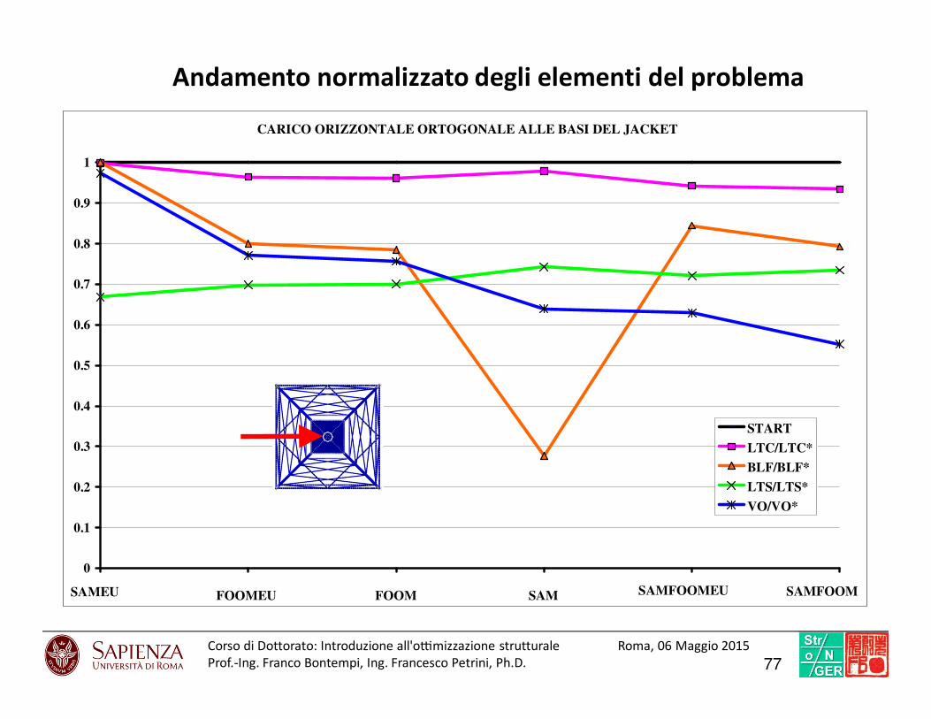
Andamento normalizzato degli elementi del problema
CARICO ORIZZONTALE ORTOGONALE ALLE BASI DEL JACKET
SAMEU SAMFOOMFOOMEU SAMFOOMEU SAMFOOM
0
0.1
0.2
0.3
0.4
0.5
0.6
0.7
0.8
0.9
1
START
LTC/LTC*
BLF/BLF*
LTS/LTS*
VO/VO*
77Corso di Dottorato: Introduzio ne all'o7mi zzazione struttural e Roma, 06 Maggio 2015
Prof.-Ing. Franco Bontempi, Ing. Francesco Petrini, Ph.D.
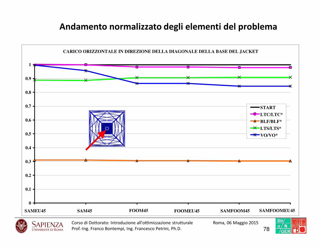
CARICO ORIZZONTALE IN DIREZIONE DELLA DIAGONALE DELLA BASE DEL JACKET
SAMEU45 SAM45 FOOM45 FOOMEU45 SAMFOOMEU45SAMFOOM45
0
0.1
0.2
0.3
0.4
0.5
0.6
0.7
0.8
0.9
1
START
LTC/LTC*
BLF/BLF*
LTS/LTS*
VO/VO*
Andamento normalizzato degli elementi del problema
78Corso di Dottorato: Introduzio ne all'o7mi zzazione struttural e Roma, 06 Maggio 2015
Prof.-Ing. Franco Bontempi, Ing. Francesco Petrini, Ph.D.
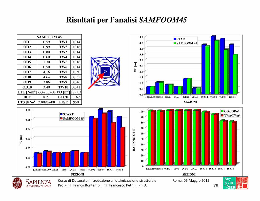
SAMFOOM 45 OD1 0,59 TW1 0,014
OD2 0,99 TW2 0,016
OD3 0,80 TW3 0,014
OD4 0,60 TW4 0,014
OD5 1,30 TW5 0,016
OD6 0,50 TW6 0,014
OD7 4,16 TW7 0,050
OD8 4,64 TW8 0,055
OD9 3,86 TW9 0,046
OD10 3,40 TW10 0,041
LTC [N/m2] -3,470E+08 VO [m3] 129,03
BLF 8,21 LTCE 1162
LTS [N/m2] 2,809E+08 LTSE 950
Risultati per l’analisi SAMFOOM45
0
10
20
30
40
50
60
70
80
90
100
RA
PP
OR
TO
[%
]
JORIZZ SOSTEGNO ORIZZ DIAG JVERT JDIAG TUBO 2 TUBO 0 TUBO 1 TUBO 2
SEZIONI
ODn/ODn*TWn/TWn*
0.00
0.01
0.02
0.03
0.04
0.05
0.06
TW
[m
]
JORIZZ SOSTEGNO ORIZZ DIAG JVERT JDIAG TUBO 2 TUBO 0 TUBO 1 TUBO 2
SEZIONI
STARTSAMFOOM 45
0.0
0.5
1.0
1.5
2.0
2.5
3.0
3.5
4.0
4.5
5.0
OD
[m
]
JORIZZ SOSTEGNO ORIZZ DIAG JVERT JDIAG TUBO 2 TUBO 0 TUBO 1 TUBO 2
SEZIONI
STARTSAMFOOM 45
79Corso di Dottorato: Introduzio ne all'o7mi zzazione struttural e Roma, 06 Maggio 2015
Prof.-Ing. Franco Bontempi, Ing. Francesco Petrini, Ph.D.

16% DI RIDUZIONEDEL VOLUMETOTALE (VO)
24% DI RIDUZIONE DEL VOLUME DELLA TORRE
1% DI RIDUZIONEDEL VOLUMEDEL JACKET
Results
80Corso di Dottorato: Introduzio ne all'o7mi zzazione struttural e Roma, 06 Maggio 2015
Prof.-Ing. Franco Bontempi, Ing. Francesco Petrini, Ph.D.
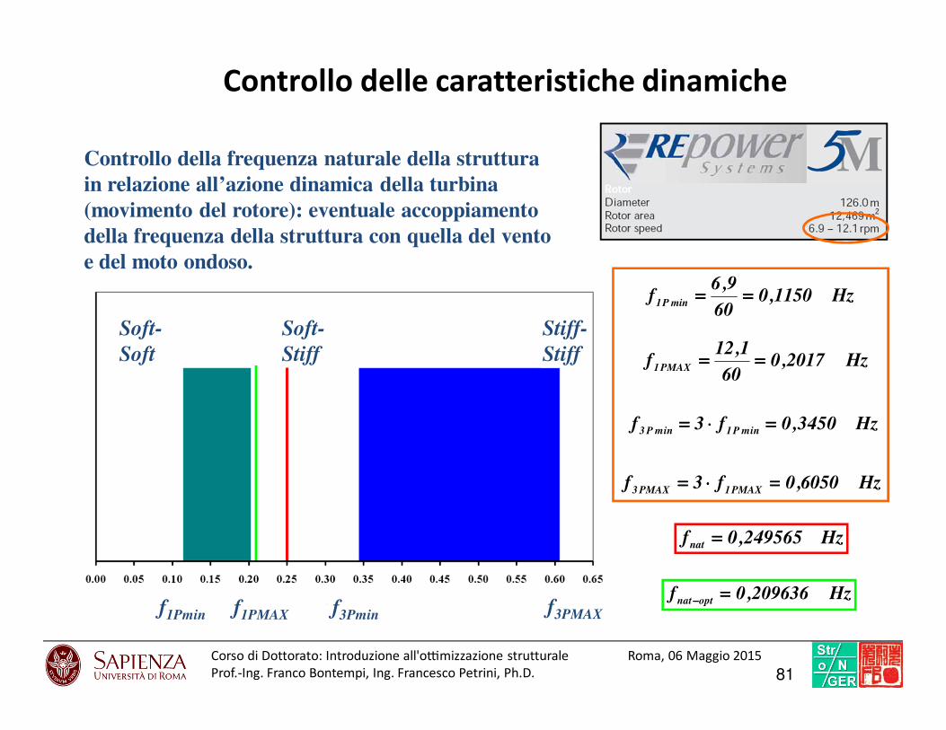
Controllo della frequenza naturale della strutturain relazione all’azione dinamica della turbina (movimento del rotore): eventuale accoppiamentodella frequenza della struttura con quella del vento e del moto ondoso.
Hz209636,0foptnat
====−−−−
Hz249565,0fnat ====
Controllo delle caratteristiche dinamiche
f1Pmin f1PMAX f3Pmin f3PMAX
Soft-
Soft
Soft-
Stiff
Stiff-
Stiff
Hz1150,060
9,6f
minP1========
Hz2017,060
1,12f
PMAX1========
Hz3450,0f3f minP1minP3 ====⋅⋅⋅⋅====
Hz6050,0f3fPMAX1PMAX3
====⋅⋅⋅⋅====
81Corso di Dottorato: Introduzio ne all'o7mi zzazione struttural e Roma, 06 Maggio 2015
Prof.-Ing. Franco Bontempi, Ing. Francesco Petrini, Ph.D.

Strutted innovative support
82

Summary
x1
x2
• Structure and piles 180 m
• Structure height: 140 m
• Immersed: 35 m
• Over water level: 105 m
Local constraints:
• maximum Von Mises ideal stress equals to
300MPa (strength criterion);
• maximum compression stress equals to
200MPa (local instability criterion);
• maximum ratio diameter/thickness equals to
100 (local instability criterion);
Global constraints:
• Eulerian buckling multiplier greater that 5;
• maximum horizontal displacement permitted
4 m.
• Objective Function: TOTAL VOLUME
83Corso di Dottorato: Introduzio ne all'o7mi zzazione struttural e Roma, 06 Maggio 2015
Prof.-Ing. Franco Bontempi, Ing. Francesco Petrini, Ph.D.
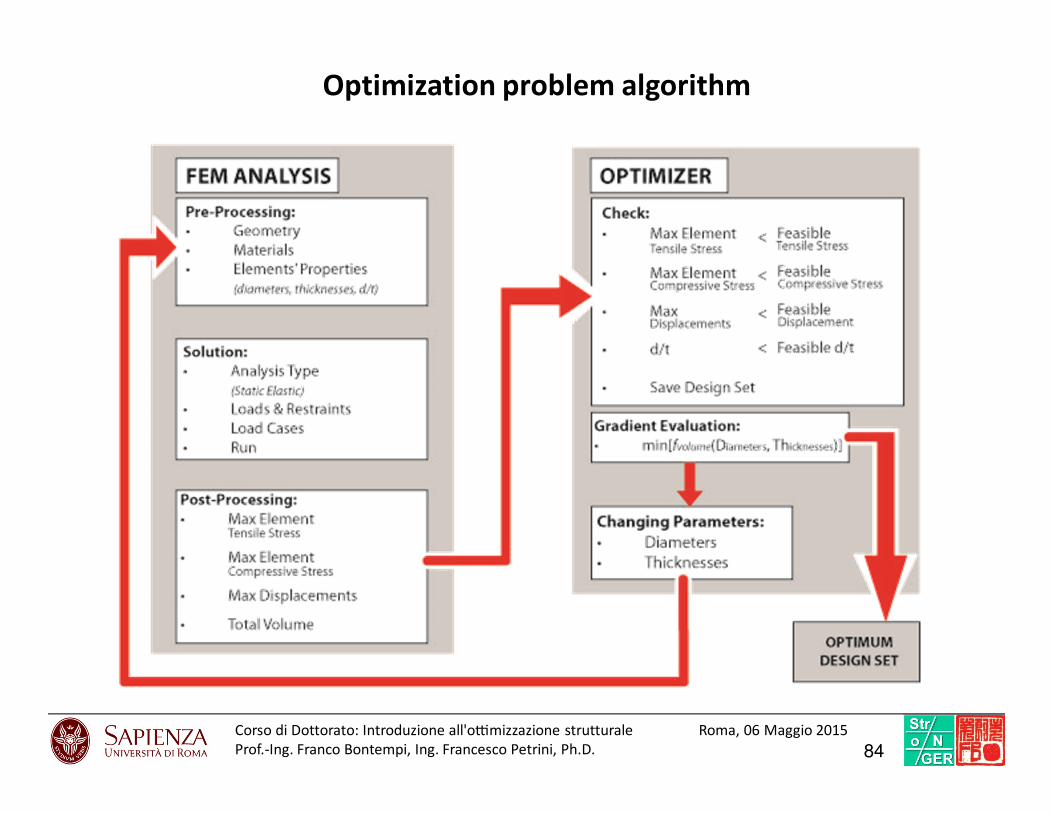
Optimization problem algorithm
84Corso di Dottorato: Introduzio ne all'o7mi zzazione struttural e Roma, 06 Maggio 2015
Prof.-Ing. Franco Bontempi, Ing. Francesco Petrini, Ph.D.
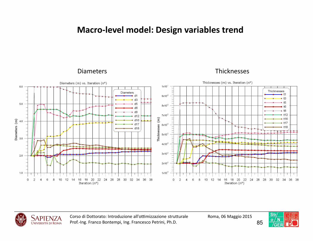
Macro-level model: Design variables trend
Diameters Thicknesses
85Corso di Dottorato: Introduzio ne all'o7mi zzazione struttural e Roma, 06 Maggio 2015
Prof.-Ing. Franco Bontempi, Ing. Francesco Petrini, Ph.D.

Macro-level model: State variables trend
Compression stresses Von Mises stresses
86Corso di Dottorato: Introduzio ne all'o7mi zzazione struttural e Roma, 06 Maggio 2015
Prof.-Ing. Franco Bontempi, Ing. Francesco Petrini, Ph.D.
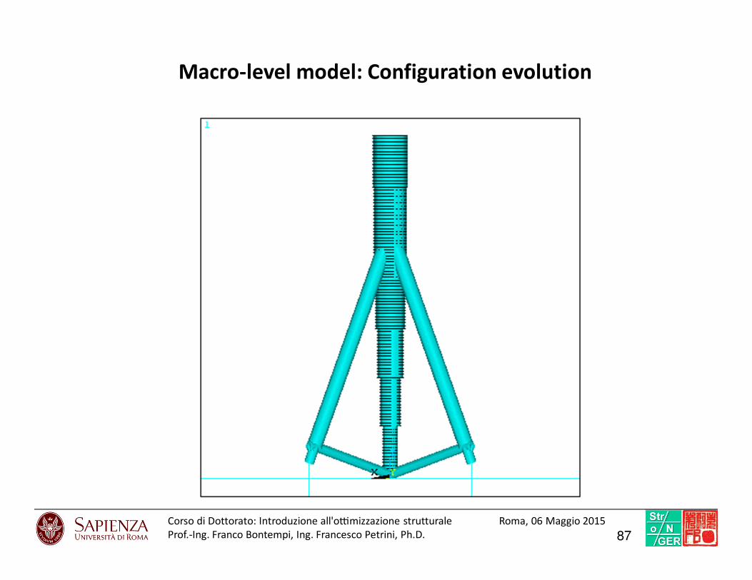
Macro-level model: Configuration evolution
87Corso di Dottorato: Introduzio ne all'o7mi zzazione struttural e Roma, 06 Maggio 2015
Prof.-Ing. Franco Bontempi, Ing. Francesco Petrini, Ph.D.
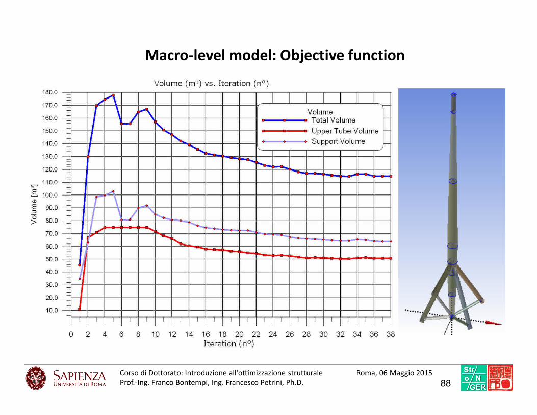
Macro-level model: Objective function
88Corso di Dottorato: Introduzio ne all'o7mi zzazione struttural e Roma, 06 Maggio 2015
Prof.-Ing. Franco Bontempi, Ing. Francesco Petrini, Ph.D.

Meso-level model
89Corso di Dottorato: Introduzio ne all'o7mi zzazione struttural e Roma, 06 Maggio 2015
Prof.-Ing. Franco Bontempi, Ing. Francesco Petrini, Ph.D.
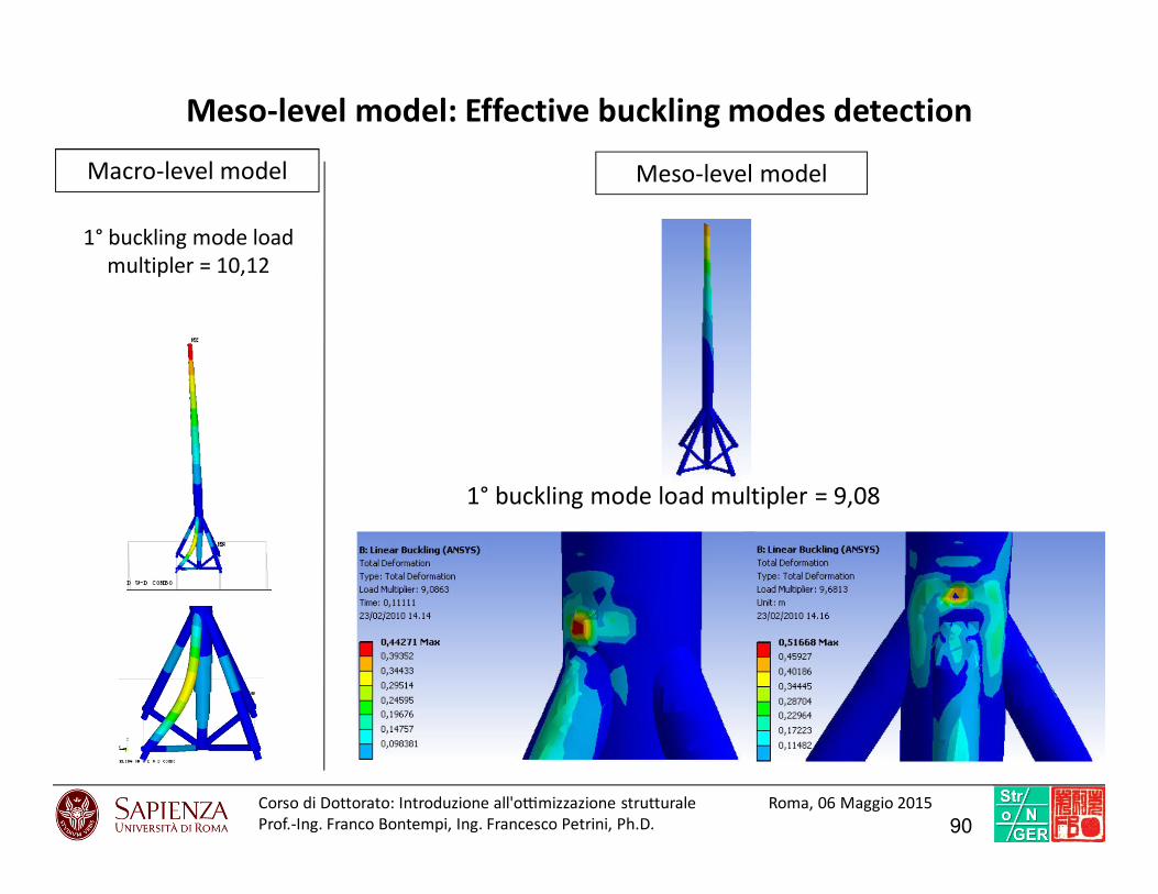
Meso-level model: Effective buckling modes detection
Macro-level model Meso-level model
1° buckling mode load multipler = 9,08
1° buckling mode load
multipler = 10,12
90Corso di Dottorato: Introduzio ne all'o7mi zzazione struttural e Roma, 06 Maggio 2015
Prof.-Ing. Franco Bontempi, Ing. Francesco Petrini, Ph.D.
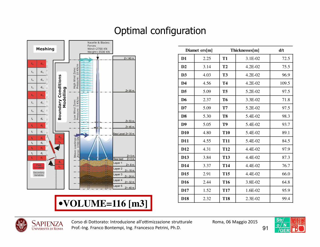
Optimal configuration
•VOLUME=116 [m3]
Diamet ers[m] Thicknesses[m] d/t
D1 2.25 T1 3.1E-02 72.5
D2 3.14 T2 4.2E-02 75.5
D3 4.03 T3 4.2E-02 96.9
D4 4.56 T4 4.2E-02 109.5
D5 5.09 T5 5.2E-02 97.5
D6 2.37 T6 3.3E-02 71.8
D7 5.09 T7 5.2E-02 97.5
D8 5.30 T8 5.4E-02 98.3
D9 5.05 T9 5.4E-02 93.7
D10 4.80 T10 5.4E-02 89.1
D11 4.55 T11 5.4E-02 84.5
D12 4.31 T12 4.4E-02 97.9
D13 3.84 T13 4.4E-02 87.3
D14 3.37 T14 4.4E-02 76.7
D15 2.91 T15 4.4E-02 66.0
D16 2.44 T16 3.8E-02 64.8
D17 1.52 T17 1.6E-02 95.9
D18 2.32 T18 2.3E-02 99.4
91Corso di Dottorato: Introduzio ne all'o7mi zzazione struttural e Roma, 06 Maggio 2015
Prof.-Ing. Franco Bontempi, Ing. Francesco Petrini, Ph.D.
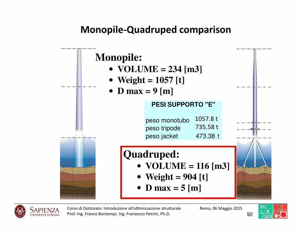
Monopile-Quadruped comparison
Quadruped:• VOLUME = 116 [m3]• Weight = 904 [t]• D max = 5 [m]
Monopile:• VOLUME = 234 [m3]• Weight = 1057 [t]• D max = 9 [m]
peso monotubo 205.78 t
peso tripode 635.58 t
peso jacket 473.38 t
PESI SUPPORTO "E"
1057.8 t
735.58 t
92Corso di Dottorato: Introduzio ne all'o7mi zzazione struttural e Roma, 06 Maggio 2015
Prof.-Ing. Franco Bontempi, Ing. Francesco Petrini, Ph.D.

Considerations on OWTs optimization
1. The Design Optimization of Owts is a fundamental step in the design of Offshore
Wind Farms.
2. The Design Optimization of such a complex structural systems has been carried out by
assuming simplified models for the actions.
3. Multi level detail models are needed in order to capture the main physical aspects.
4. A new support structure is proposed here, the optimization produced good results in
terms of weight if compared with another feasible solution (a monopile support
structure).
93Corso di Dottorato: Introduzio ne all'o7mi zzazione struttural e Roma, 06 Maggio 2015
Prof.-Ing. Franco Bontempi, Ing. Francesco Petrini, Ph.D.
PERFORMANCE-BASED OPTIMIZATION
OF AN HIGH-RISE BUILDING FOR WIND• Performance-Based Wind Engineering (PBWE) procedure
• Models for tall buildings and Occupant Comfort assessment
• Probabilistic Performance-Based analysis
• Probabilistic Performance-Based optimization by a TMD
94FB
Performance-Based Wind Engineering (PBWE) procedure
95

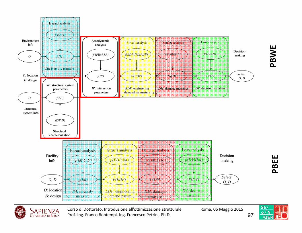
The problem of risk assessment is disaggregated into the following elements:
- site and structure-specific hazard analyses, that is, the assessment of the probability density
functions f(IM), f(SP) and f(IP|IM, SP);
- structural analysis, aimed at assessing the probability density function of the structural response
f(EDP|IM,IP,SP) conditional on the parameters characterizing the environmental actions, the
wind-fluid-structure interaction and the structural properties;
- damage analysis, that gives the damage probability density function f(DM|EDP) conditional on
EDP;
- finally, loss analysis, that is the assessment of G(DV|DM), where G(·|·) is a conditional
complementary cumulative distribution function.
G(DV) = ∫…∫ G(DV|DM) · f(DM|EDP) · f(EDP|IM, IP, SP) · f(IP|IM,SP) ·
· f(IM) · f(SP) · dDM · dEDP · dIP · dIM · dSP
PBWE procedure
Interaction
Parameters
Structural
Parameters
Intensity
measureIM IP SP
Engineering
Demand
Parameters
EDPDamage
MeasureDM
Decision
VariableDV
96Corso di Dottorato: Introduzio ne all'o7mi zzazione struttural e Roma, 06 Maggio 2015
Prof.-Ing. Franco Bontempi, Ing. Francesco Petrini, Ph.D.
O
f(IM|O)
f(IM)f(IP|IM,SP)
f(IP)
f(EDP|IM,IP,SP)
G(EDP)
f(DM|EDP)
G(DM)
f(DV|DM)
G(DV)
Hazard analysis
Aerodynamic
analysisStruc’l analysis Damage analysis Loss analysis
IM: intensity measure
IP: interaction
parameters
EDP: engineering
demand parameters
DM: damage measures DV: decision variables
Select
O, DO: location
D: design
Environment
info
Decision-
making
D
f(SP|D)
f(SP)
Structural
characterization
SP: structural system
parameters
Structural
system info
O, D
g(IM|O,D)
g(IM)
p(EDP|IM)
P(EDP)
p(DM|EDP)
P(DM)
p(DV|DM)
P(DV)
Hazard analysis Struc’l analysis Damage analysis Loss analysis
IM: intensity
measure
EDP: engineering
demand param.DM: damage
measure
DV: decision
variable
Select
O, D
O: location
D: design
Facility
info
Decision-
making
O, D
g(IM|O,D)
g(IM)
p(EDP|IM)
P(EDP)
p(DM|EDP)
P(DM)
p(DV|DM)
P(DV)
Hazard analysis Struc’l analysis Damage analysis Loss analysis
IM: intensity
measure
EDP: engineering
demand param.DM: damage
measure
DV: decision
variable
Select
O, D
O: location
D: design
Facility
info
Decision-
making
PB
WE
PB
EE
97Corso di Dottorato: Introduzio ne all'o7mi zzazione struttural e Roma, 06 Maggio 2015
Prof.-Ing. Franco Bontempi, Ing. Francesco Petrini, Ph.D.

Models for tall buildings and Occupant
Comfort assessment
98
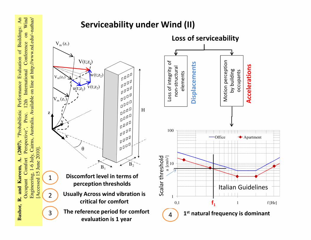
Loss of serviceability
Loss
of
inte
gri
ty o
f
no
n-s
tru
ctu
ral
ele
me
nts
Mo
tio
n p
erc
ep
tio
n
by b
uild
ing
occ
up
an
ts
Bas
hor,
R.
and
Kar
eem
,A
.(2
007)
."P
rob
abil
isti
cP
erfo
rman
ceE
val
uat
ion
of
Bu
ildin
gs:
An
Occ
up
ant
Co
mfo
rtP
ersp
ecti
ve"
,P
roc.
12
thIn
tern
atio
nal
Co
nfe
ren
ceon
Win
d
En
gin
eeri
ng,
1-6
July
,C
airn
s,A
ust
rali
a.A
vai
lable
on
line
athtt
p:/
/ww
w.n
d.e
du/~
nat
haz
/
[Acc
esse
d1
5Ju
ne
20
10
].
w(t;z2)Vm(z2)
Vm (z1)
Vm (z3)
V(t;z2)
v(t;z2)u(t;z2)
X
Z
Y
θ
B1
B2
H
Dis
pla
cem
en
ts
Acc
ele
rati
on
s
Discomfort level in terms of
perception thresholds
Usually Across wind vibration is
critical for comfort
The reference period for comfort
evaluation is 1 year
1
2
3 1st natural frequency is dominant4
1
10
100
0,1 1
a [
cm/s
2]
f [Hz]
Office Apartment
Italian Guidelines
f1
Sca
lar
thre
sho
ld
Serviceability under Wind (II)
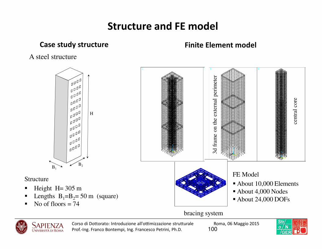
Case study structure
Structure and FE model
Structure
Height H= 305 m
Lengths B1=B2= 50 m (square)
No of floors = 74
3d f
ram
e o
n t
he
exte
rnal
per
imet
er
centr
al c
ore
bracing system
A steel structure
Finite Element model
B1
B2
H
FE Model
About 10,000 Elements
About 4,000 Nodes
About 24,000 DOFs
100Corso di Dottorato: Introduzio ne all'o7mi zzazione struttural e Roma, 06 Maggio 2015
Prof.-Ing. Franco Bontempi, Ing. Francesco Petrini, Ph.D.

Experimental model of Actions
Spen
ceS.
M.J
.,G
ioff
rèM
.,G
usel
laV
.(20
08a)
.In
flu
ence
of
hig
her
mo
des
on
the
dy
nam
ic
re-s
po
nse
of
irre
gula
rand
regula
rta
llb
uil
din
gs,
Pro
c.6
thIn
tern
atio
nal
Co
lloq
uiu
mo
nB
luff
Bod
ies
Aer
od
ynam
ics
and
Ap
pli
cati
ons
(BB
AA
VI)
,M
ilan
o,
Ital
y,Ju
ly20-2
4,
2008.
Boundary Layer Wind Tunnel of
the CRIACIV in Prato, Italy
-60
-40
-20
0
20
40
60
80
100
120
140
3000 3200 3400 3600 3800
F [KN]
t [s]
Along Across
1:5
00
S
cale
mo
de
l
Response time
history
Time domain structural analyses
(Experimental actions)
Time domain
analyses
Experimental
forces
Time domain analyses
-30
-20
-10
0
10
20
30
3500 3600 3700 3800 3900 4000
aL, aD
[cm/s2]
t [s]Along Across
( )
( )
( ) )(),(
),,(exp1
),(),(
22
212
2
ωχωρ
ωξξ
ωρω
⋅⋅⋅⋅=
=⋅⋅−⋅
⋅⋅⋅⋅=
∫ ∫
hSVc
dAdAfA
hSVchS
uumxD
A A
uumxDDD tt
( )
)(),h(S
)(HVc
),h(S)(H),h(S
2
uu
22
mxD
DD
2
rr tttt
ωχω
ωρ
ωωω
⋅⋅
⋅⋅⋅⋅
=⋅=
⋅+
−
⋅
⋅⋅
=
2
0
2
2
2
0
2
2
0
2
2
41
1
1)(
ω
ων
ω
ω
ωω
mH
rrm
pgrr σ⋅+= rg
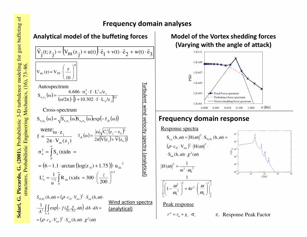
Wind action spectra
(analytical)
Response spectra
Peak response
Frequency domain response
Frequency domain analyses
Response Peak Factor
Analytical model of the buffeting forces
( ) ( ) ( ) ( )( )ωfexpωSωSωS jkuuuuuu kkjjkj−=
( )( )
( ) ( )( )kj
2
kj
2
z
jkzVzV2π
zzCωωf
+
−=
Cross-spectrum
5.0
0
uu2
x
u200
300(x)dxRu
1L
⋅== ∫
∞z
were:
( )( ) [ ]5/3
ju
jux2
u
uu/zLf10.3021ω/2π
/zLfσ6.686ωS
jj ⋅⋅+⋅
⋅⋅⋅=
( )( ) 2
fri0
0
u
2
u
u1.75)log(zarctan1.16
(n)dnSσ
⋅+⋅−=
== ∫∞
)z(V2π
zωf
jm
j
⋅
⋅=
Autospectrum
( )3ew(t)2ev(t)1eu(t))
j(zmV)
jz(t;
jV
rrrr⋅+⋅+⋅+=
α
10m
10
zV(z)V
⋅=
Sola
ri,G
.Pic
card
o,G
.(20
01).
Pro
bab
ilis
tic
3-D
turb
ule
nce
mo
deli
ng
for
gust
bu
ffet
ing
of
stru
cture
s,P
robab
ilis
tic
Engin
eeri
ng
Mec
han
ics,
(16),
73
–8
6.
Turb
ule
nt w
ind
velo
city sp
ectra
(an
aly
tical)
Model of the Vortex shedding forces
(Varying with the angle of attack)
1.E+01
1.E+03
1.E+05
1.E+07
1.E+09
1.E+11
0.000 0.001 0.010 0.100 1.000
PS
D
n [Hz]
Total Force spectrum
Turbulence force spectrum
Vortex shedding force spectrum

Exp
erim
en
tal w
ind
force
spe
ctra
Extra
po
latio
n o
f an
an
aly
tical
Vo
rtex sh
ed
din
g fo
rce sp
ectra
Model of the Vortex shedding forces
n
Co
mp
atib
ility o
f an
aly
tical
an
d e
xpe
rime
nta
l spe
ctra
1.E+01
1.E+03
1.E+05
1.E+07
1.E+09
1.E+11
0.000 0.001 0.010 0.100 1.000
PS
D
n [Hz]
Total Force spectrum
Turbulent component
Vortex shedding component
Global force spectrum
Analytical wind spectra
n
103Corso di Dottorato: Introduzio ne all'o7mi zzazione struttural e Roma, 06 Maggio 2015
Prof.-Ing. Franco Bontempi, Ing. Francesco Petrini, Ph.D.
1
10
100
0.1 1
aL
,Dp
[cm
/s2]
n [Hz]
Office Apartment aLp aD
p
f1
aL
,Dp
[cm
/s2]
n [Hz]
-30
-20
-10
0
10
20
30
3500 3600 3700 3800 3900 4000
aL, aD
[cm/s2]
t [s]Along Across
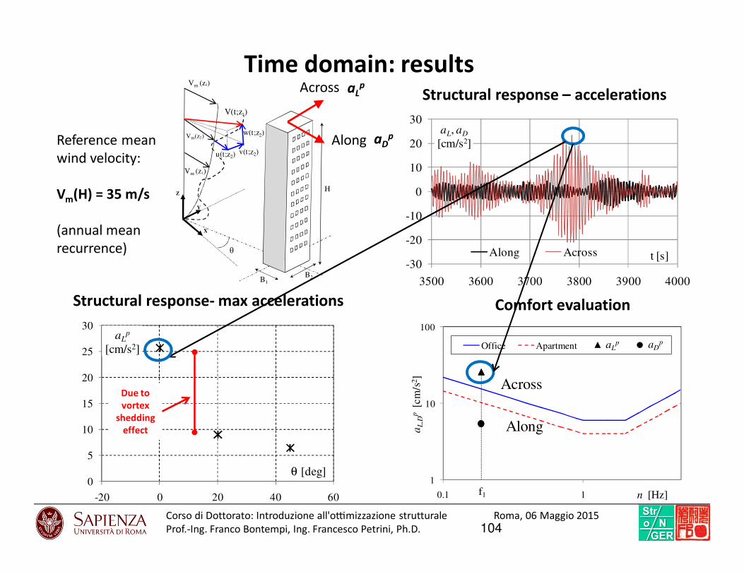
Structural response- max accelerations
Time domain: resultsStructural response – accelerations
Comfort evaluation
Across
Along
Reference mean
wind velocity:
Vm(H) = 35 m/s
(annual mean
recurrence)
Alongw(t;z2)Vm(z2)
Vm (z1)
Vm (z3)
V(t;z2)
v(t;z2)u(t;z2)
X
Z
Y
θ
B1
B2
H
Across
0
5
10
15
20
25
30
-20 0 20 40 60
aLp
[cm/s2]
θ [deg]
aLp
aDp
Due to
vortex
shedding
effect
104Corso di Dottorato: Introduzio ne all'o7mi zzazione struttural e Roma, 06 Maggio 2015
Prof.-Ing. Franco Bontempi, Ing. Francesco Petrini, Ph.D.
Probabilistic Performance-Based analysis
105
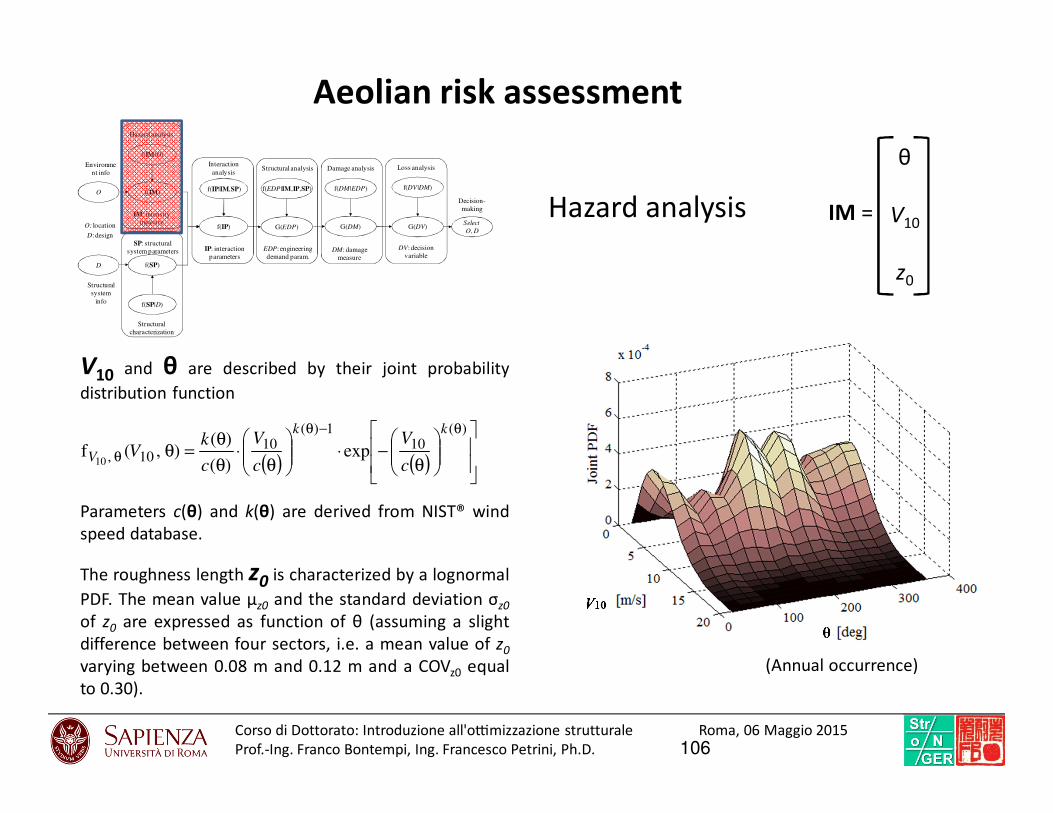
Hazard analysis
Aeolian risk assessment
O
f(IM|O)
f(IM)f(IP|IM,SP)
f(IP)
f(EDP|IM,IP,SP)
G(EDP)
f(DM|EDP)
G(DM)
f(DV|DM)
G(DV)
Hazard analysis
Interaction
analysisStructural analysis Damage analysis Loss analysis
IM: intensity
measure
IP: interaction
parameters
EDP: engineering
demand param.DM: damage
measure
DV: decision
variable
Select
O, DO: location
D: design
Environme
nt info
Decision-
making
D
f(SP|D)
f(SP)
Structural
characterization
SP: structural
system parameters
Structural
system
info
( ) ( )
θ−⋅
θ⋅
θ
θ=θ
θ−θ
θ
)(10
1)(10
10, exp)(
)(),(f
10
kk
Vc
V
c
V
c
kV
The roughness length z0 is characterized by a lognormal
PDF. The mean value μz0 and the standard deviation σz0
of z0 are expressed as function of θ (assuming a slight
difference between four sectors, i.e. a mean value of z0
varying between 0.08 m and 0.12 m and a COVz0 equal
to 0.30).
V10 and θ are described by their joint probability
distribution function
IM =
θ
V10
z0
Parameters c(θ) and k(θ) are derived from NIST® wind
speed database.
(Annual occurrence)
106Corso di Dottorato: Introduzio ne all'o7mi zzazione struttural e Roma, 06 Maggio 2015
Prof.-Ing. Franco Bontempi, Ing. Francesco Petrini, Ph.D.
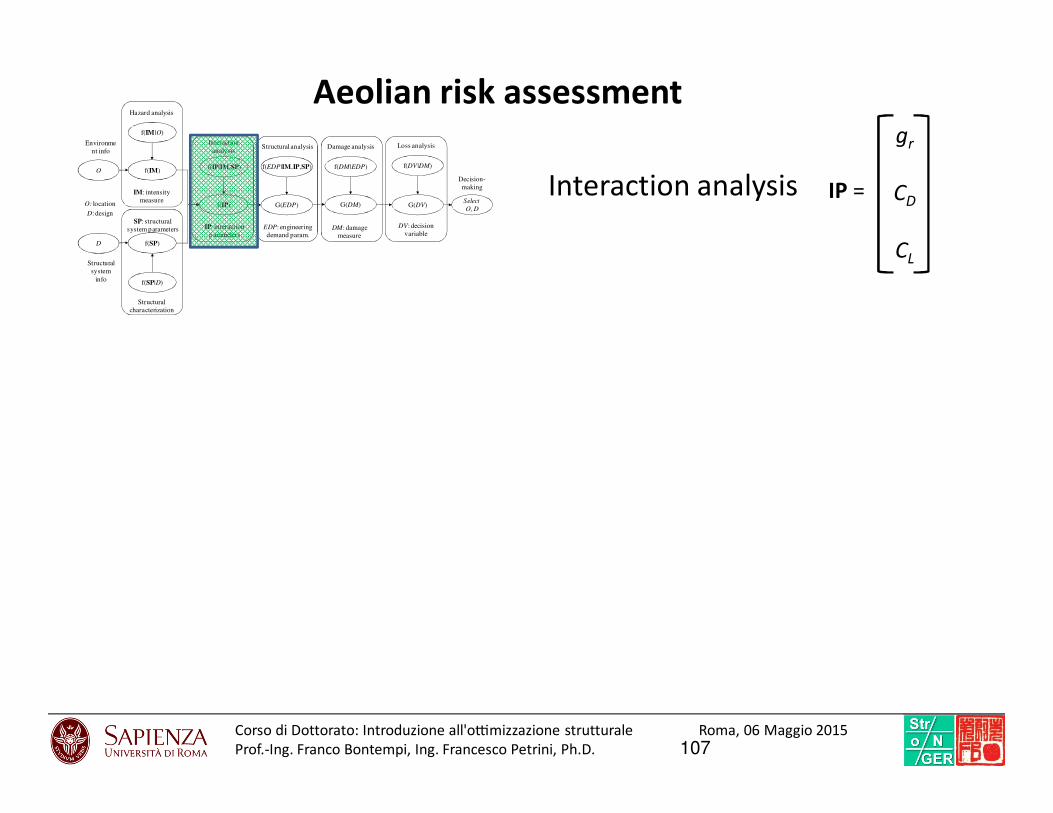
Interaction analysis IP =
gr
CD
CL
O
f(IM|O)
f(IM)f(IP|IM,SP)
f(IP)
f(EDP|IM,IP,SP)
G(EDP)
f(DM|EDP)
G(DM)
f(DV|DM)
G(DV)
Hazard analysis
Interaction
analysisStructural analysis Damage analysis Loss analysis
IM: intensity
measure
IP: interaction
parametersEDP: engineering
demand param.DM: damage
measure
DV: decision
variable
Select
O, DO: location
D: design
Environme
nt info
Decision-
making
D
f(SP|D)
f(SP)
Structural
characterization
SP: structural
system parameters
Structural
system
info
Aeolian risk assessment
107Corso di Dottorato: Introduzio ne all'o7mi zzazione struttural e Roma, 06 Maggio 2015
Prof.-Ing. Franco Bontempi, Ing. Francesco Petrini, Ph.D.
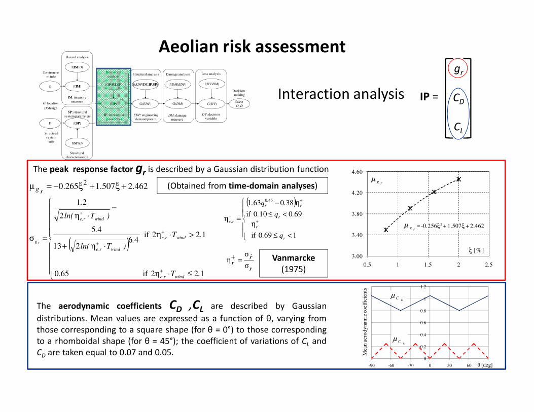
Interaction analysis
The aerodynamic coefficients CD ,CL are described by Gaussian
distributions. Mean values are expressed as a function of θ, varying from
those corresponding to a square shape (for θ = 0°) to those corresponding
to a rhomboidal shape (for θ = 45°); the coefficient of variations of CL and
CD are taken equal to 0.07 and 0.05.
IP =
gr
CD
CL
O
f(IM|O)
f(IM)f(IP|IM,SP)
f(IP)
f(EDP|IM,IP,SP)
G(EDP)
f(DM|EDP)
G(DM)
f(DV|DM)
G(DV)
Hazard analysis
Interaction
analysisStructural analysis Damage analysis Loss analysis
IM: intensity
measure
IP: interaction
parametersEDP: engineering
demand param.DM: damage
measure
DV: decision
variable
Select
O, DO: location
D: design
Environme
nt info
Decision-
making
D
f(SP|D)
f(SP)
Structural
characterization
SP: structural
system parameters
Structural
system
info
0
0.2
0.4
0.6
0.8
1
1.2
-90 -60 -30 0 30 60 90M
ean
aer
od
ynam
ic c
oef
fici
ents
µ µ
DCµ
60 90
θ [deg]
LCµ
462.2507.1265.02 +ξ+ξ−=µ
rg
( )
≤⋅η
>⋅η
⋅η+
−⋅η
=σ
+
+
+
+
122if650
122if46
213
45
2
21
.T.
.T.
)Tln(
.
)Tln(
.
windr,e
windr,e
windr,e
windr,e
gr
( )
<≤
η
<≤
η−
=η +
+
+
1690if
690100if
380631 450
r
r
r
r
.
r
r,e
q.
.q.
.q.
r
rr σ
σ=+η & Vanmarcke
(1975)
(Obtained from time-domain analyses)
The peak response factor gr is described by a Gaussian distribution function
g*r = -0.256ξ2 + 1.507ξ + 2.462
3.00
3.40
3.80
4.20
4.60
0.5 1 1.5 2 2.5
g*r
ξ [%]
rgµ
rgµ
Aeolian risk assessment
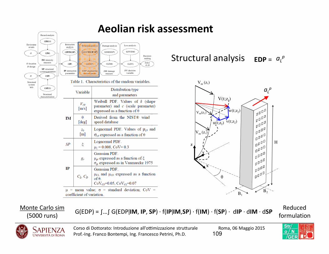
Structural analysis EDP = aLp
O
f(IM|O)
f(IM)f(IP|IM,SP)
f(IP)
f(EDP|IM,IP,SP)
G(EDP)
f(DM|EDP)
G(DM)
f(DV|DM)
G(DV)
Hazard analysis
Interaction
analysisStructural analysis Damage analysis Loss analysis
IM: intensity
measure
IP: interaction
parametersEDP: engineering
demand param.DM: damage
measure
DV: decision
variable
Select
O, DO: location
D: design
Environme
nt info
Decision-
making
D
f(SP|D)
f(SP)
Structural
characterization
SP: structural
system parameters
Structural
system
info
G(EDP) = ∫…∫ G(EDP|IM, IP, SP) · f(IP|IM,SP) · f(IM) · f(SP) · dIP · dIM · dSPMonte Carlo sim
(5000 runs)
w(t;z2)Vm(z2)
Vm (z1)
Vm (z3)
V(t;z2)
v(t;z2)u(t;z2)
X
Z
Y
θ
B1
B2
H
aLp
Reduced
formulation
Aeolian risk assessment
109Corso di Dottorato: Introduzio ne all'o7mi zzazione struttural e Roma, 06 Maggio 2015
Prof.-Ing. Franco Bontempi, Ing. Francesco Petrini, Ph.D.
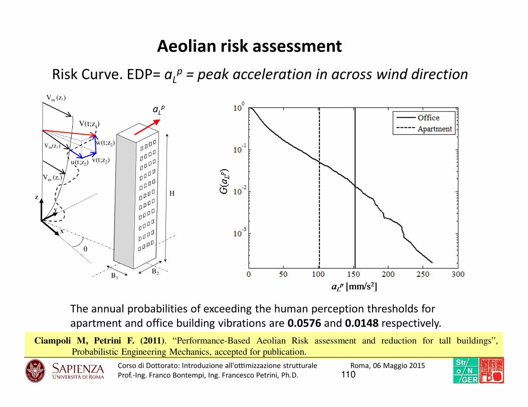
Risk Curve. EDP= aLp = peak acceleration in across wind direction
The annual probabilities of exceeding the human perception thresholds for
apartment and office building vibrations are 0.0576 and 0.0148 respectively.
w(t;z2)Vm(z2)
Vm (z1)
Vm (z3)
V(t;z2)
v(t;z2)u(t;z2)
X
Z
Y
θ
B1
B2
H
aLp
Ciampoli M, Petrini F. (2011). “Performance-Based Aeolian Risk assessment and reduction for tall buildings”,
Probabilistic Engineering Mechanics, accepted for publication.
Aeolian risk assessment
110Corso di Dottorato: Introduzio ne all'o7mi zzazione struttural e Roma, 06 Maggio 2015
Prof.-Ing. Franco Bontempi, Ing. Francesco Petrini, Ph.D.

Probabilistic Performance-Based optimization by a TMD
111

TUNED MASS DAMPER (TMD)
C1
K1 CTMD
KTMD
M1
MTMD
112Corso di Dottorato: Introduzio ne all'o7mi zzazione struttural e Roma, 06 Maggio 2015
Prof.-Ing. Franco Bontempi, Ing. Francesco Petrini, Ph.D.
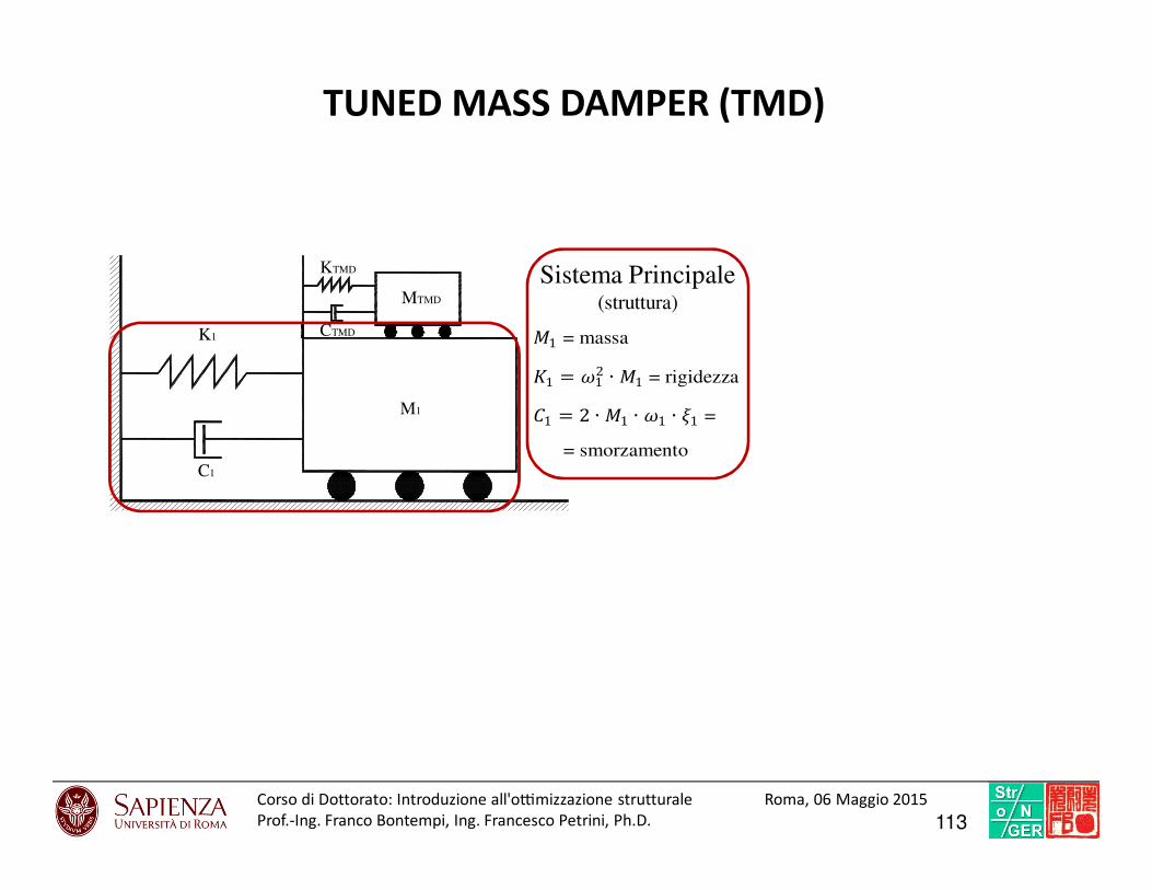
C1
K1 CTMD
KTMD
M1
MTMD
Sistema Principale(struttura)1 = massa 1 = 12 ∙ 1 = rigidezza 1 = 2 ∙ 1 ∙ 1 ∙ 1 =
= smorzamento
TUNED MASS DAMPER (TMD)
113Corso di Dottorato: Introduzio ne all'o7mi zzazione struttural e Roma, 06 Maggio 2015
Prof.-Ing. Franco Bontempi, Ing. Francesco Petrini, Ph.D.
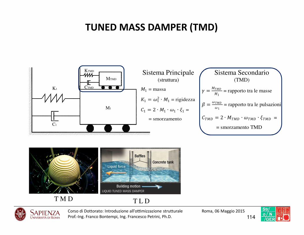
C1
K1 CTMD
KTMD
M1
MTMD
Sistema Principale(struttura)
Sistema Secondario(TMD) = 1 = rapporto tra le masse
= 1 = rapporto tra le pulsazioni
= 2 ∙ ∙ ∙ =
= smorzamento TMD
T M D T L D
1 = massa 1 = 12 ∙ 1 = rigidezza 1 = 2 ∙ 1 ∙ 1 ∙ 1 =
= smorzamento
TUNED MASS DAMPER (TMD)
114Corso di Dottorato: Introduzio ne all'o7mi zzazione struttural e Roma, 06 Maggio 2015
Prof.-Ing. Franco Bontempi, Ing. Francesco Petrini, Ph.D.
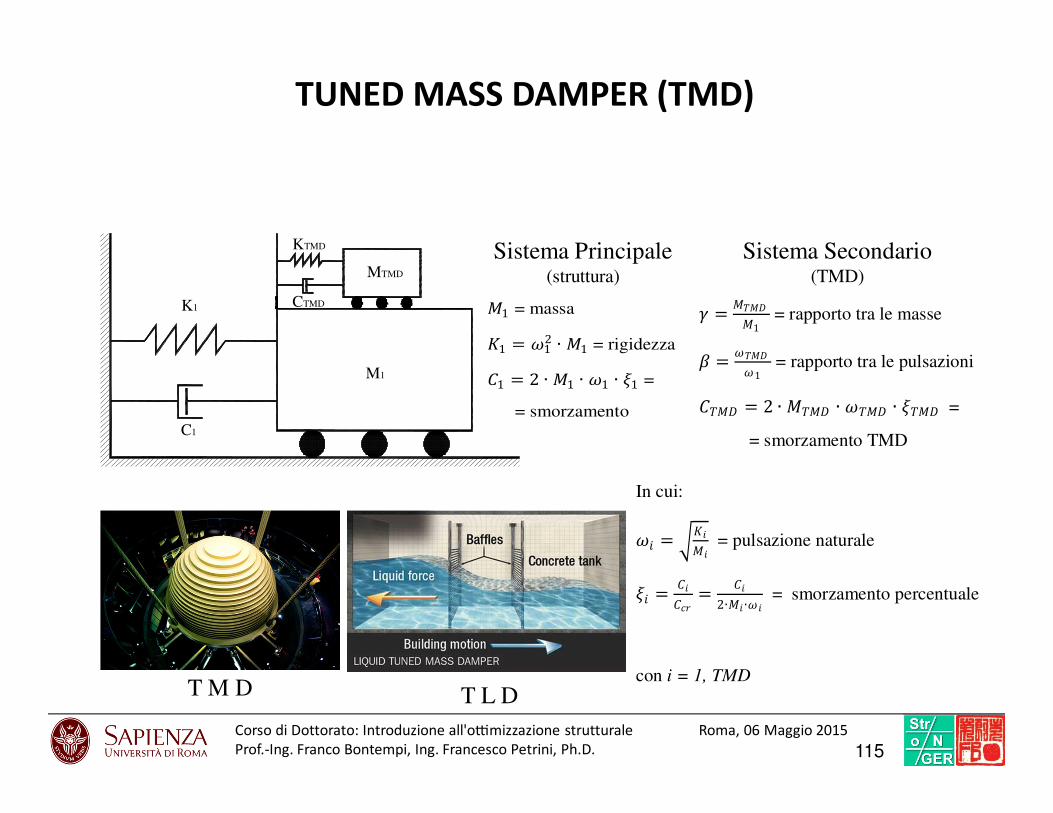
C1
K1 CTMD
KTMD
M1
MTMD
Sistema Principale(struttura) = 1 = rapporto tra le masse
= 1 = rapporto tra le pulsazioni
= 2 ∙ ∙ ∙ =
= smorzamento TMD
In cui:
= = pulsazione naturale
= = 2∙ ∙ = smorzamento percentuale
con i = 1, TMD T M D T L D
1 = massa 1 = 12 ∙ 1 = rigidezza 1 = 2 ∙ 1 ∙ 1 ∙ 1 =
= smorzamento
Sistema Secondario(TMD)
TUNED MASS DAMPER (TMD)
115Corso di Dottorato: Introduzio ne all'o7mi zzazione struttural e Roma, 06 Maggio 2015
Prof.-Ing. Franco Bontempi, Ing. Francesco Petrini, Ph.D.
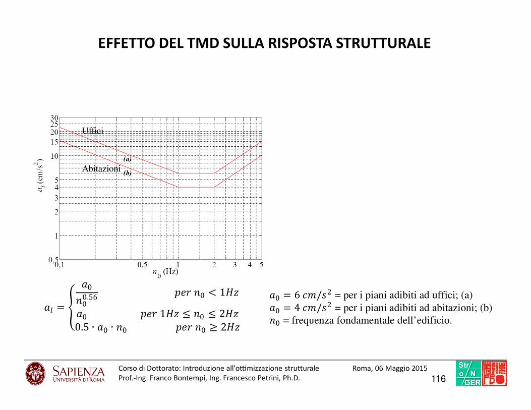
= 000.56 0 < 10 1 ≤ 0 ≤ 20.5 ∙ 0 ∙ 0 0 ≥ 2"
0 = 6 #/%2 = per i piani adibiti ad uffici; (a) 0 = 4 #/%2 = per i piani adibiti ad abitazioni; (b) 0 = frequenza fondamentale dell’edificio.
Uffici
Abitazioni
EFFETTO DEL TMD SULLA RISPOSTA STRUTTURALE
116Corso di Dottorato: Introduzio ne all'o7mi zzazione struttural e Roma, 06 Maggio 2015
Prof.-Ing. Franco Bontempi, Ing. Francesco Petrini, Ph.D.
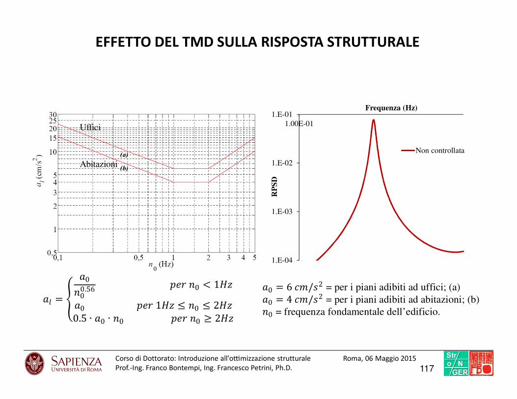
= 000.56 0 < 10 1 ≤ 0 ≤ 20.5 ∙ 0 ∙ 0 0 ≥ 2"
0 = 6 #/%2 = per i piani adibiti ad uffici; (a) 0 = 4 #/%2 = per i piani adibiti ad abitazioni; (b) 0 = frequenza fondamentale dell’edificio.
Uffici
Abitazioni
1.E-04
1.E-03
1.E-02
1.E-01
1.00E-01
RP
SD
Frequenza (Hz)
Non controllata
EFFETTO DEL TMD SULLA RISPOSTA STRUTTURALE
117Corso di Dottorato: Introduzio ne all'o7mi zzazione struttural e Roma, 06 Maggio 2015
Prof.-Ing. Franco Bontempi, Ing. Francesco Petrini, Ph.D.
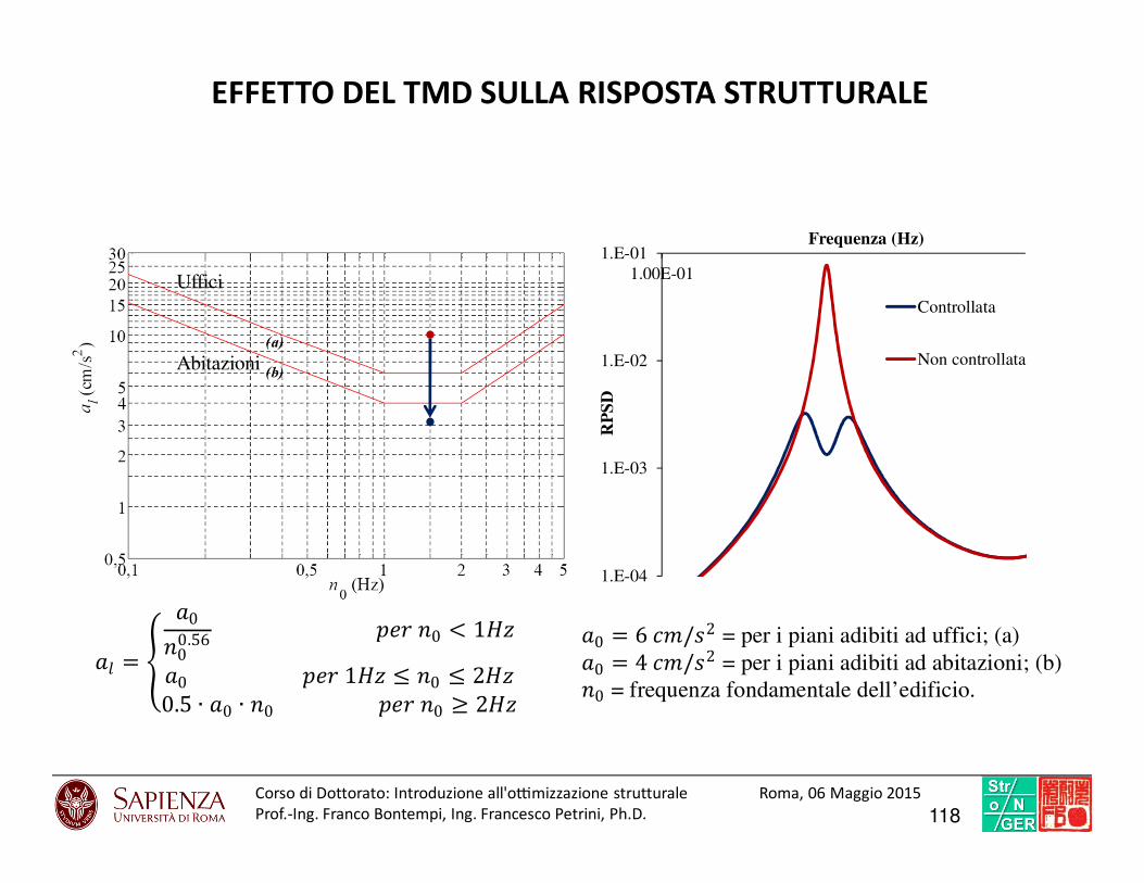
= 000.56 0 < 10 1 ≤ 0 ≤ 20.5 ∙ 0 ∙ 0 0 ≥ 2"
0 = 6 #/%2 = per i piani adibiti ad uffici; (a) 0 = 4 #/%2 = per i piani adibiti ad abitazioni; (b) 0 = frequenza fondamentale dell’edificio.
Uffici
Abitazioni
1.E-04
1.E-03
1.E-02
1.E-01
1.00E-01
RP
SD
Frequenza (Hz)
Controllata
Non controllata
EFFETTO DEL TMD SULLA RISPOSTA STRUTTURALE
118Corso di Dottorato: Introduzio ne all'o7mi zzazione struttural e Roma, 06 Maggio 2015
Prof.-Ing. Franco Bontempi, Ing. Francesco Petrini, Ph.D.
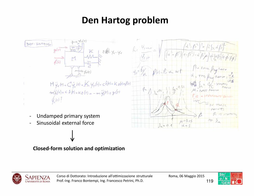
119Corso di Dottorato: Introduzio ne all'o7mi zzazione struttural e Roma, 06 Maggio 2015
Prof.-Ing. Franco Bontempi, Ing. Francesco Petrini, Ph.D.
- Undamped primary system
- Sinusoidal external force
Closed-form solution and optimization
Den Hartog problem

120Corso di Dottorato: Introduzio ne all'o7mi zzazione struttural e Roma, 06 Maggio 2015
Prof.-Ing. Franco Bontempi, Ing. Francesco Petrini, Ph.D.
Modal superposition resolution method (I)
[ ]∑=
⋅≈
p
ii
iiTMD
i
TMD
tytyt
t
1 2
11
1)()(
)(
)(
φ
φ
ξ
ξ
Strømmen E., Hansen E.H. (2001). On the use of tuned mass dampers to suppress vortex shedding induced vibrations. Wind and Structures, 4(1), 19-30.
Each mode shape a 2 DoF modal
problem is solved
Physical response parameter (e.g. displacement) of the primary structure
Solution response parameter (e.g. displacement) of the primary structure
for modal problem i
Modal shape displacement value of the primary structure
)(1 tξ
)(1 tyi
i1φ
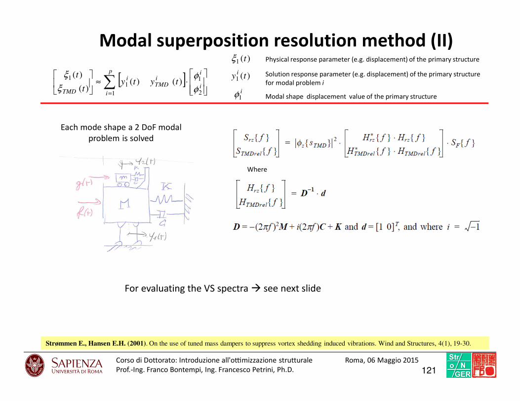
121Corso di Dottorato: Introduzio ne all'o7mi zzazione struttural e Roma, 06 Maggio 2015
Prof.-Ing. Franco Bontempi, Ing. Francesco Petrini, Ph.D.
Modal superposition resolution method (II)
Strømmen E., Hansen E.H. (2001). On the use of tuned mass dampers to suppress vortex shedding induced vibrations. Wind and Structures, 4(1), 19-30.
[ ]∑=
⋅≈
p
ii
iiTMD
i
TMD
tytyt
t
1 2
11
1)()(
)(
)(
φ
φ
ξ
ξ
Each mode shape a 2 DoF modal
problem is solved
Physical response parameter (e.g. displacement) of the primary structure
Solution response parameter (e.g. displacement) of the primary structure
for modal problem i
Modal shape displacement value of the primary structure
)(1 tξ
)(1 tyi
i1φ
Where
For evaluating the VS spectra see next slide

Optimization parameters
Design Parameters
γ = mTMD/mtot
β = ωTMD/ ω1
ξ* = damping of TMD
122Corso di Dottorato: Introduzio ne all'o7mi zzazione struttural e Roma, 06 Maggio 2015
Prof.-Ing. Franco Bontempi, Ing. Francesco Petrini, Ph.D.
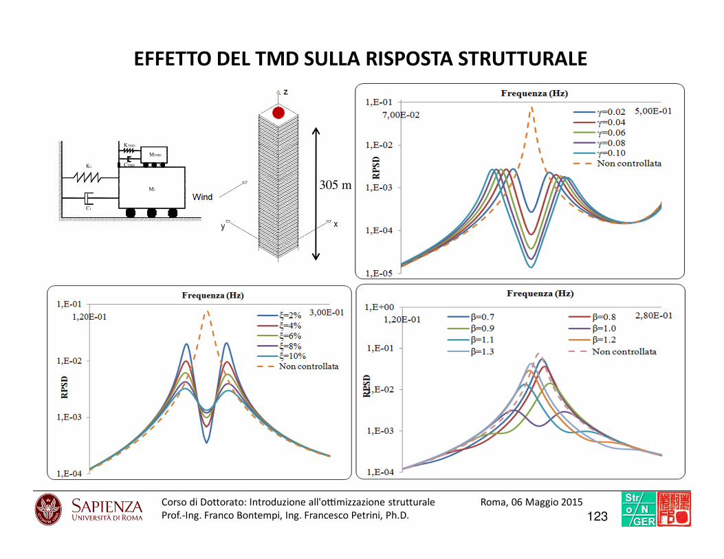
C1
K1 CTMD
KTMD
M1
MTMD
EFFETTO DEL TMD SULLA RISPOSTA STRUTTURALE
305 m
123Corso di Dottorato: Introduzio ne all'o7mi zzazione struttural e Roma, 06 Maggio 2015
Prof.-Ing. Franco Bontempi, Ing. Francesco Petrini, Ph.D.
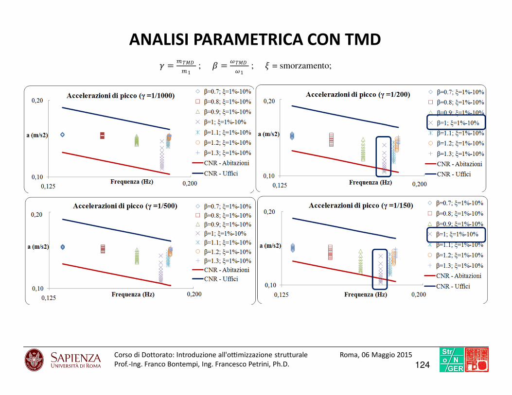
ANALISI PARAMETRICA CON TMD
= ##1 ; = 1 ; = smorzamento;
124Corso di Dottorato: Introduzio ne all'o7mi zzazione struttural e Roma, 06 Maggio 2015
Prof.-Ing. Franco Bontempi, Ing. Francesco Petrini, Ph.D.
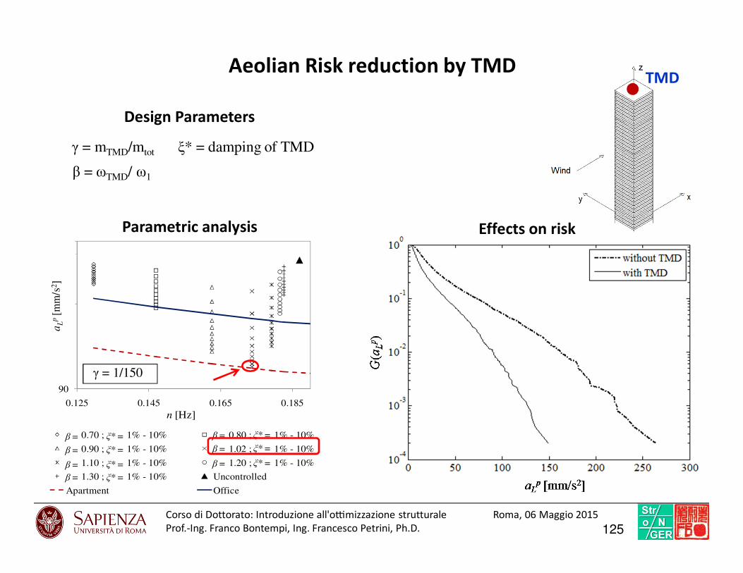
TMD
Design Parameters
γ = mTMD/mtot
β = ωTMD/ ω1
ξ* = damping of TMD
Aeolian Risk reduction by TMD
90
0.125 0.145 0.165 0.185
β = 0.70 ; ξ* = 1% - 10% β = 0.80 ; ξ* = 1% - 10%
β = 0.90 ; ξ* = 1% - 10% β = 1.02 ; ξ* = 1% - 10%
β = 1.10 ; ξ* = 1% - 10% β = 1.20 ; ξ* = 1% - 10%
β = 1.30 ; ξ* = 1% - 10% Uncontrolled
Apartment Office
aL
p[m
m/s
2]
n [Hz]
β = ξ* =
β = ξ* =
β = ξ* =
β = ξ* =
β = ξ* =
β = ξ* =
β = ξ* =
Parametric analysis Effects on risk
γ = 1/150
125Corso di Dottorato: Introduzio ne all'o7mi zzazione struttural e Roma, 06 Maggio 2015
Prof.-Ing. Franco Bontempi, Ing. Francesco Petrini, Ph.D.
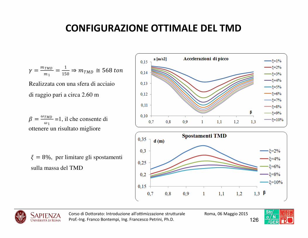
CONFIGURAZIONE OTTIMALE DEL TMD
= # # 1 = 1150 ⇒ # ≅ 568 *+
Realizzata con una sfera di acciaio
di raggio pari a circa 2.60 m
= 8%, per limitare gli spostamenti
sulla massa del TMD
= 1 =1, il che consente di
ottenere un risultato migliore
126Corso di Dottorato: Introduzio ne all'o7mi zzazione struttural e Roma, 06 Maggio 2015
Prof.-Ing. Franco Bontempi, Ing. Francesco Petrini, Ph.D.
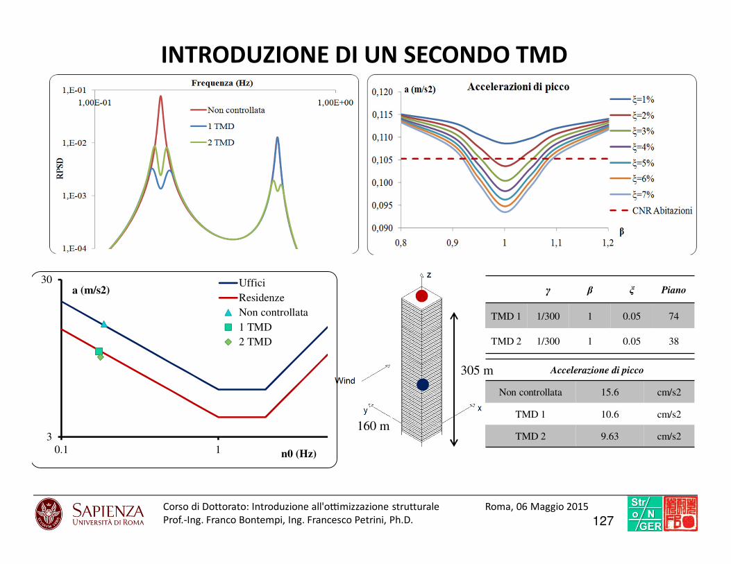
INTRODUZIONE DI UN SECONDO TMD
Accelerazione di picco
Non controllata 15.6 cm/s2
TMD 1 10.6 cm/s2
TMD 2 9.63 cm/s2
γ β ξ Piano
TMD 1 1/300 1 0.05 74
TMD 2 1/300 1 0.05 38
305 m
160 m3
30
0.1 1
a (m/s2)
n0 (Hz)
Uffici
Residenze
Non controllata
1 TMD
2 TMD
127Corso di Dottorato: Introduzio ne all'o7mi zzazione struttural e Roma, 06 Maggio 2015
Prof.-Ing. Franco Bontempi, Ing. Francesco Petrini, Ph.D.
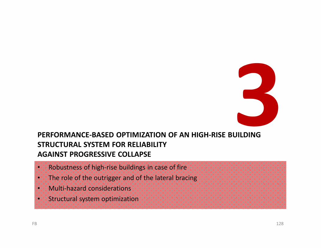
PERFORMANCE-BASED OPTIMIZATION OF AN HIGH-RISE BUILDING
STRUCTURAL SYSTEM FOR RELIABILITY
AGAINST PROGRESSIVE COLLAPSE
• Robustness of high-rise buildings in case of fire
• The role of the outrigger and of the lateral bracing
• Multi-hazard considerations
• Structural system optimization
128FB
Robustness of high-rise buildings
in case of fire
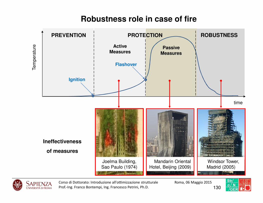
time
Tem
pera
ture
PREVENTION PROTECTION
Passive Measures
Ignition
Flashover
Active Measures
ROBUSTNESS
Ineffectiveness
of measures
Robustness role in case of fire
Joelma Building,
Sao Paulo (1974)
Mandarin Oriental
Hotel, Beijing (2009)
Windsor Tower,
Madrid (2005)
130Corso di Dottorato: Introduzio ne all'o7mi zzazione struttural e Roma, 06 Maggio 2015
Prof.-Ing. Franco Bontempi, Ing. Francesco Petrini, Ph.D.
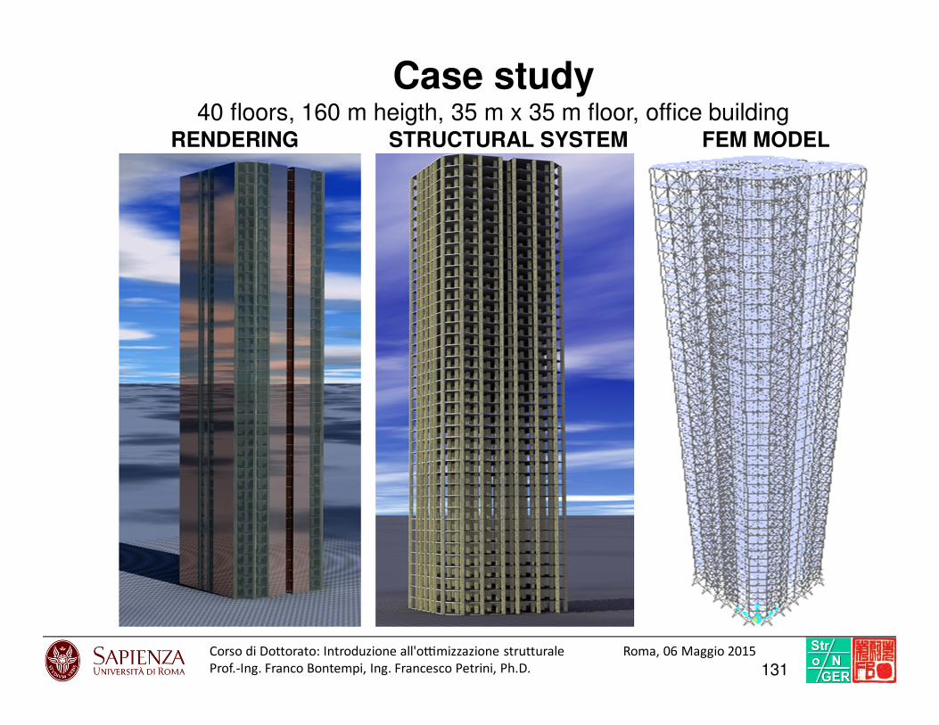
Case study40 floors, 160 m heigth, 35 m x 35 m floor, office building
RENDERING STRUCTURAL SYSTEM FEM MODEL
131Corso di Dottorato: Introduzio ne all'o7mi zzazione struttural e Roma, 06 Maggio 2015
Prof.-Ing. Franco Bontempi, Ing. Francesco Petrini, Ph.D.
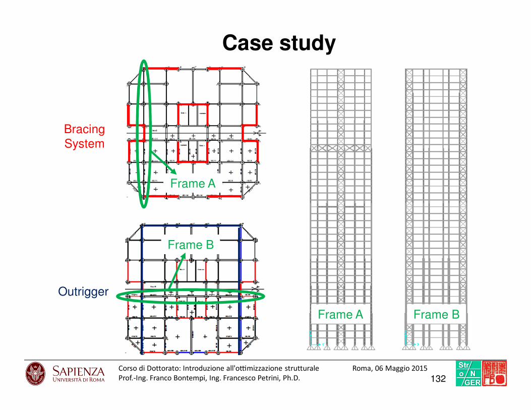
Case study
Outrigger
Bracing
System
Frame BFrame A
Frame B
Frame A
132Corso di Dottorato: Introduzio ne all'o7mi zzazione struttural e Roma, 06 Maggio 2015
Prof.-Ing. Franco Bontempi, Ing. Francesco Petrini, Ph.D.
The role of the outrigger and of
the lateral bracing
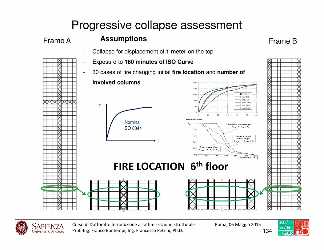
Frame A Assumptions
- Collapse for displacement of 1 meter on the top
- Exposure to 180 minutes of ISO Curve
- 30 cases of fire changing initial fire location and number of
involved columns
Frame B
FIRE LOCATION 6th floor
t
T
Nominal
ISO 8344
0
200
400
600
800
1000
0 10 20 30 40 50 60
ISO 834
θ ipe 270
θ ipe 300
θ hem 260
θ hea 240
θ hem280
Progressive collapse assessment
134Corso di Dottorato: Introduzio ne all'o7mi zzazione struttural e Roma, 06 Maggio 2015
Prof.-Ing. Franco Bontempi, Ing. Francesco Petrini, Ph.D.

Progressive collapse assessment
Frame A Assumptions
- Collapse for displacement of 1 meter on the top
- Exposure to 180 minutes of ISO Curve
- 30 cases of fire changing initial fire location and number of
involved columns
Frame B
135Corso di Dottorato: Introduzio ne all'o7mi zzazione struttural e Roma, 06 Maggio 2015
Prof.-Ing. Franco Bontempi, Ing. Francesco Petrini, Ph.D.
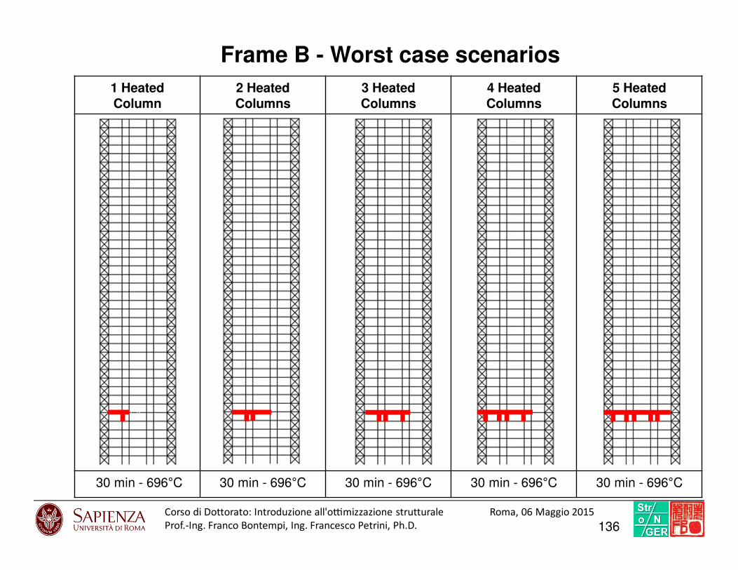
1 Heated Column
2 Heated Columns
3 Heated Columns
4 Heated Columns
5 Heated Columns
30 min - 696°C 30 min - 696°C 30 min - 696°C 30 min - 696°C 30 min - 696°C
Frame B - Worst case scenarios
136Corso di Dottorato: Introduzio ne all'o7mi zzazione struttural e Roma, 06 Maggio 2015
Prof.-Ing. Franco Bontempi, Ing. Francesco Petrini, Ph.D.
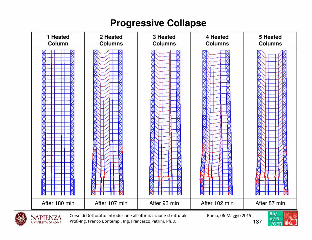
Progressive Collapse
1 Heated Column
2 Heated Columns
3 Heated Columns
4 Heated Columns
5 Heated Columns
After 180 min After 107 min After 93 min After 102 min After 87 min
137Corso di Dottorato: Introduzio ne all'o7mi zzazione struttural e Roma, 06 Maggio 2015
Prof.-Ing. Franco Bontempi, Ing. Francesco Petrini, Ph.D.
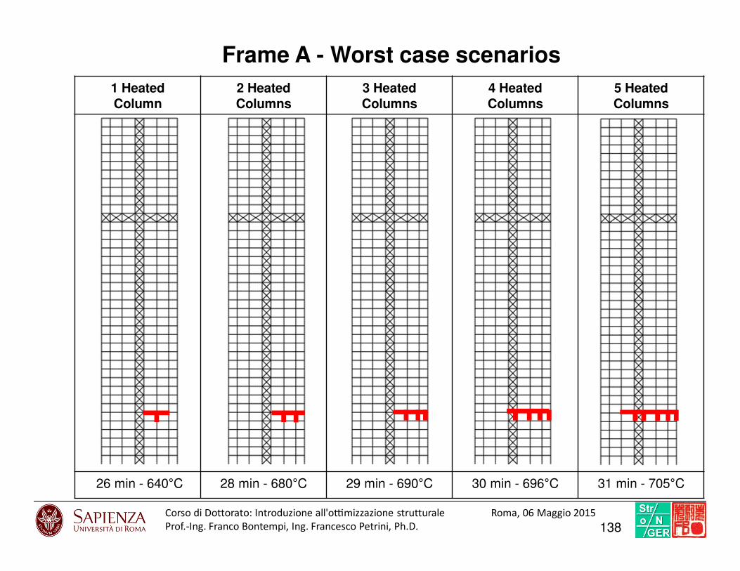
Frame A - Worst case scenarios
1 Heated Column
2 Heated Columns
3 Heated Columns
4 Heated Columns
5 Heated Columns
26 min - 640°C 28 min - 680°C 29 min - 690°C 30 min - 696°C 31 min - 705°C
138Corso di Dottorato: Introduzio ne all'o7mi zzazione struttural e Roma, 06 Maggio 2015
Prof.-Ing. Franco Bontempi, Ing. Francesco Petrini, Ph.D.
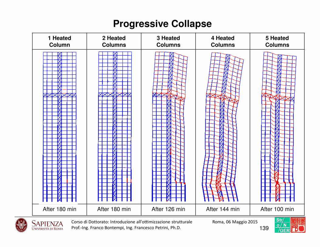
1 Heated Column
2 Heated Columns
3 Heated Columns
4 Heated Columns
5 Heated Columns
After 180 min After 180 min After 126 min After 144 min After 100 min
Progressive Collapse
139Corso di Dottorato: Introduzio ne all'o7mi zzazione struttural e Roma, 06 Maggio 2015
Prof.-Ing. Franco Bontempi, Ing. Francesco Petrini, Ph.D.

Outrigger role
VMises Deformation
Without Fire
1 Heated
Column
2 Heated
Columns
3 Heated
Columns
4 Heated
Columns
5 Heated
Columns
195235 156 117 78 39 0 plastic elastic
140Corso di Dottorato: Introduzio ne all'o7mi zzazione struttural e Roma, 06 Maggio 2015
Prof.-Ing. Franco Bontempi, Ing. Francesco Petrini, Ph.D.
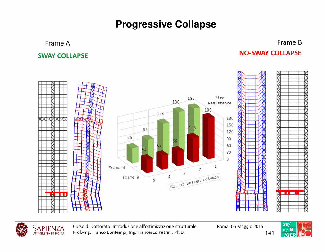
Frame BFrame A
SWAY COLLAPSE NO-SWAY COLLAPSE
Progressive Collapse
141Corso di Dottorato: Introduzio ne all'o7mi zzazione struttural e Roma, 06 Maggio 2015
Prof.-Ing. Franco Bontempi, Ing. Francesco Petrini, Ph.D.

Multi-hazard considerations
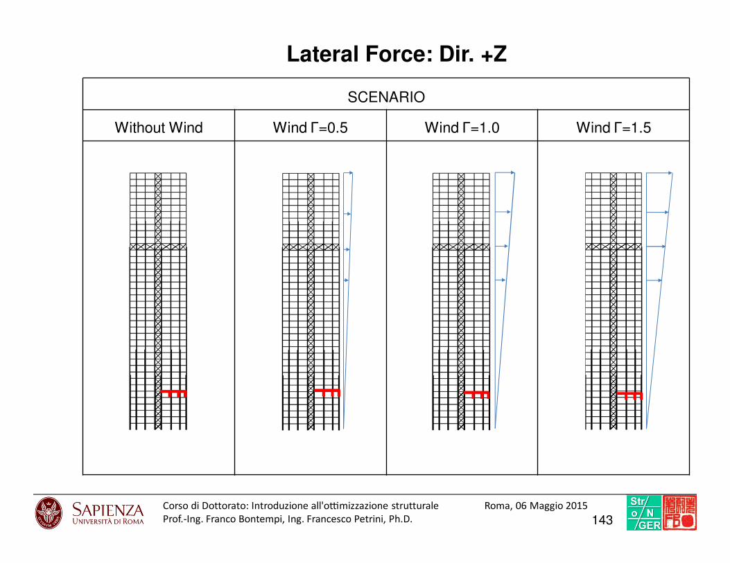
Lateral Force: Dir. +Z
SCENARIO
Without Wind Wind Γ=0.5 Wind Γ=1.0 Wind Γ=1.5
143Corso di Dottorato: Introduzio ne all'o7mi zzazione struttural e Roma, 06 Maggio 2015
Prof.-Ing. Franco Bontempi, Ing. Francesco Petrini, Ph.D.
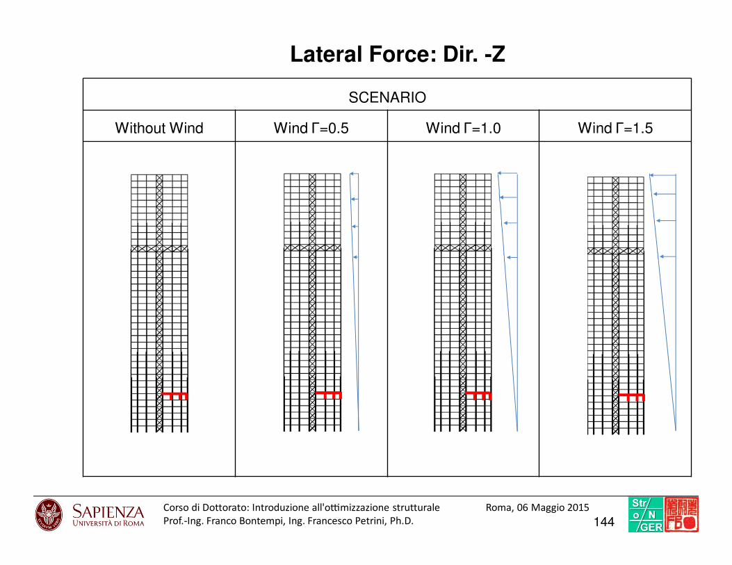
SCENARIO
Without Wind Wind Γ=0.5 Wind Γ=1.0 Wind Γ=1.5
Lateral Force: Dir. -Z
144Corso di Dottorato: Introduzio ne all'o7mi zzazione struttural e Roma, 06 Maggio 2015
Prof.-Ing. Franco Bontempi, Ing. Francesco Petrini, Ph.D.
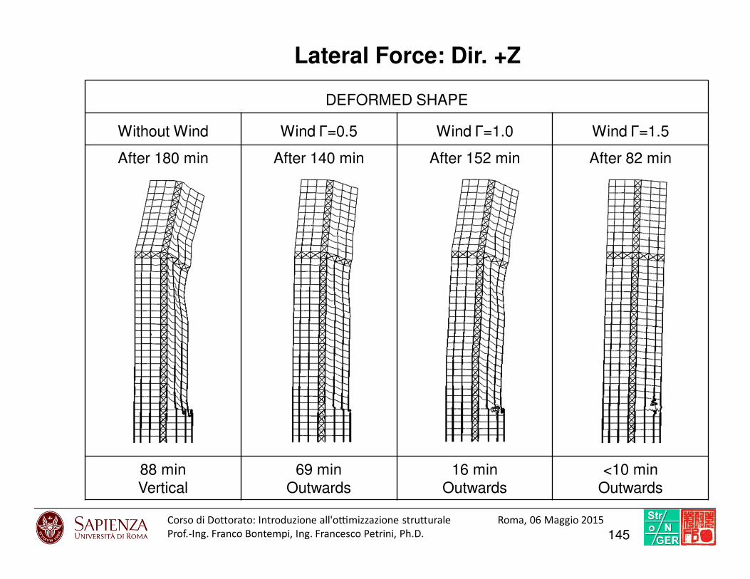
Lateral Force: Dir. +Z
DEFORMED SHAPE
Without Wind Wind Γ=0.5 Wind Γ=1.0 Wind Γ=1.5
After 180 min After 140 min After 152 min After 82 min
88 minVertical
69 minOutwards
16 minOutwards
<10 minOutwards
145Corso di Dottorato: Introduzio ne all'o7mi zzazione struttural e Roma, 06 Maggio 2015
Prof.-Ing. Franco Bontempi, Ing. Francesco Petrini, Ph.D.

Structural system optimization

Configurations: position of the outrigger
CONFIGURATIONS
G A B C
STEEL MASS [TON]
877 857 877 877
147Corso di Dottorato: Introduzio ne all'o7mi zzazione struttural e Roma, 06 Maggio 2015
Prof.-Ing. Franco Bontempi, Ing. Francesco Petrini, Ph.D.
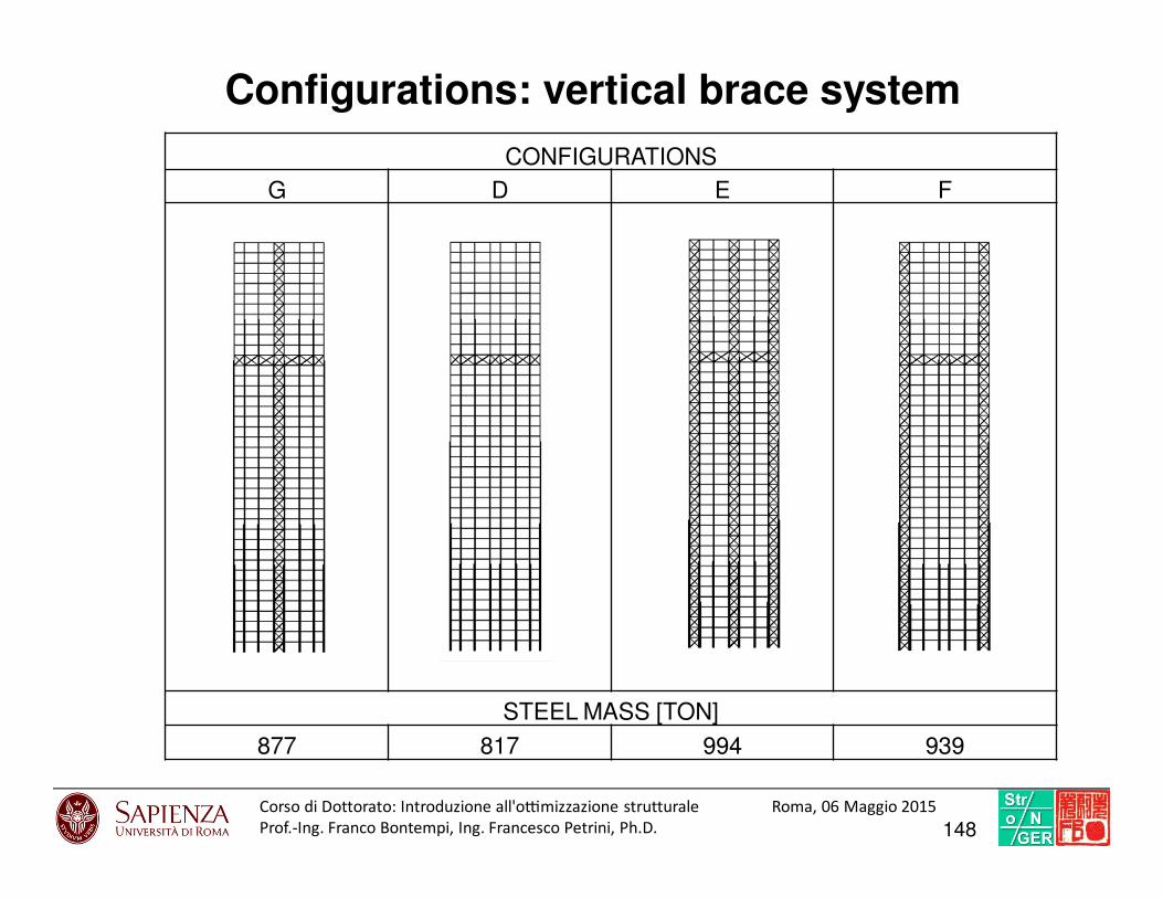
Configurations: vertical brace system
CONFIGURATIONS
G D E F
STEEL MASS [TON]
877 817 994 939
148Corso di Dottorato: Introduzio ne all'o7mi zzazione struttural e Roma, 06 Maggio 2015
Prof.-Ing. Franco Bontempi, Ing. Francesco Petrini, Ph.D.
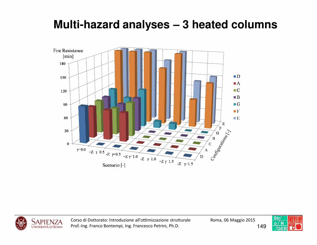
Multi-hazard analyses – 3 heated columns
149Corso di Dottorato: Introduzio ne all'o7mi zzazione struttural e Roma, 06 Maggio 2015
Prof.-Ing. Franco Bontempi, Ing. Francesco Petrini, Ph.D.
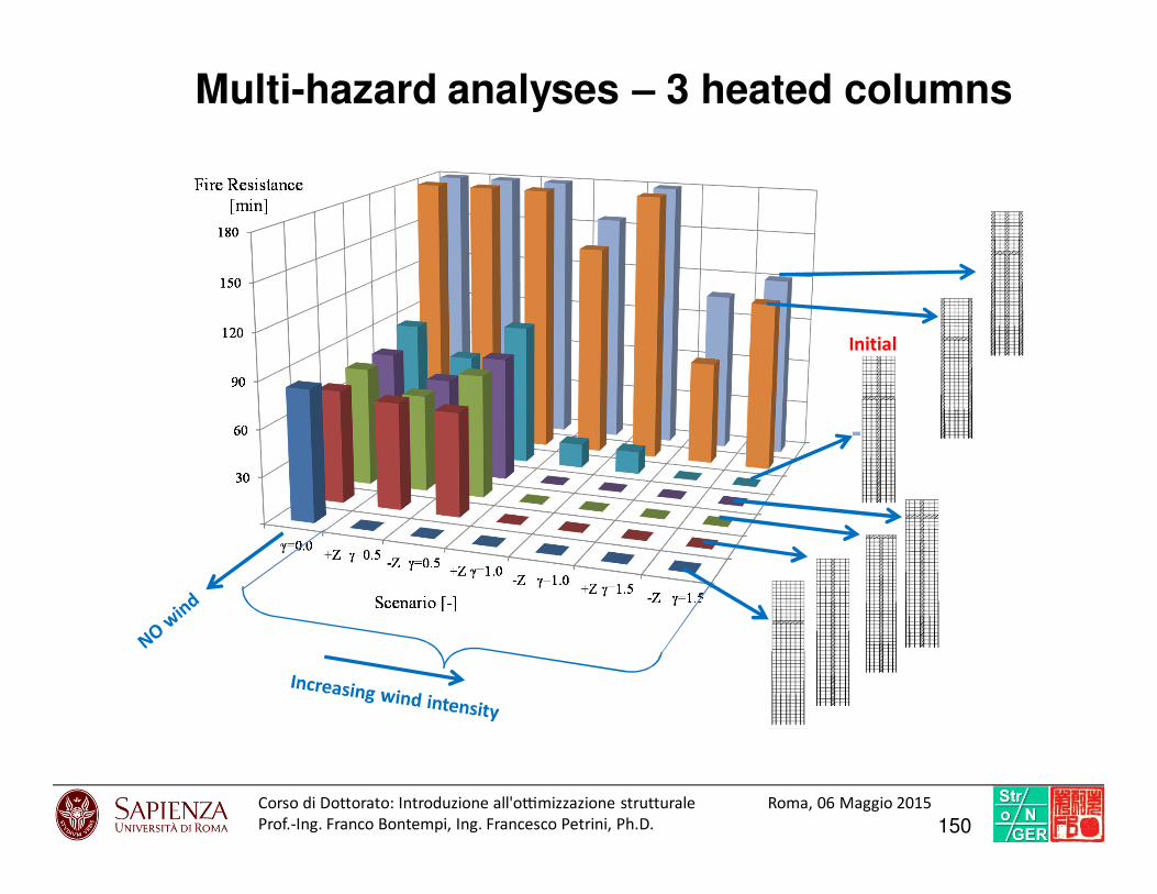
Multi-hazard analyses – 3 heated columns
Initial
150Corso di Dottorato: Introduzio ne all'o7mi zzazione struttural e Roma, 06 Maggio 2015
Prof.-Ing. Franco Bontempi, Ing. Francesco Petrini, Ph.D.
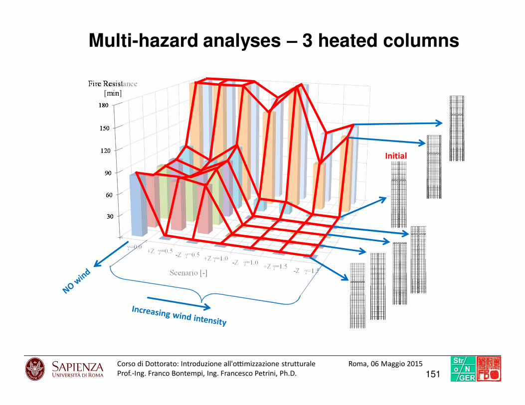
Multi-hazard analyses – 3 heated columns
Initial
151Corso di Dottorato: Introduzio ne all'o7mi zzazione struttural e Roma, 06 Maggio 2015
Prof.-Ing. Franco Bontempi, Ing. Francesco Petrini, Ph.D.
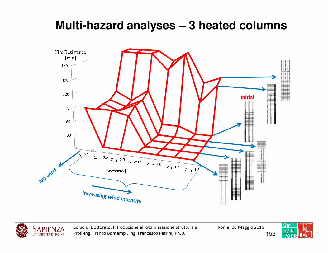
Multi-hazard analyses – 3 heated columns
Initial
152Corso di Dottorato: Introduzio ne all'o7mi zzazione struttural e Roma, 06 Maggio 2015
Prof.-Ing. Franco Bontempi, Ing. Francesco Petrini, Ph.D.
153
CONCLUSIONS

1. Due to their nature complex, real structures requires advanced models, both for
actions and structural parts.
2. A suitable way to deal with the above is the adoption of a systemic approach, that is
the switching from the vision of a structure as an isolated entity to the vision of a
structure as “a set of interrelated components which interact one with another in an
organized fashion toward a common purpose”.
3. The systemic vision is particularly useful in presence of non-linear interactions (i.e.
between the structure and the environment), cascading effects, high level of
uncertainty.
4. Classical optimization algorithms are, in general, not exhaustive for conducting the
optimization of such a structural systems, if not coupled with rational, heuristic
considerations from the designer.
5. One of the most rational way to deal with the design of complex structures is the
Performance-Based Design approach, that can be conducted both in deterministic
or in probabilistic terms.
6. The Performance-Based Optimization is an appropriate way to optimize complex
structural systems.
154Corso di Dottorato: Introduzio ne all'o7mi zzazione struttural e Roma, 06 Maggio 2015
Prof.-Ing. Franco Bontempi, Ing. Francesco Petrini, Ph.D.